JP2006322744A - Dissolution tester - Google Patents
Dissolution testerDownload PDFInfo
- Publication number
- JP2006322744A JP2006322744AJP2005144172AJP2005144172AJP2006322744AJP 2006322744 AJP2006322744 AJP 2006322744AJP 2005144172 AJP2005144172 AJP 2005144172AJP 2005144172 AJP2005144172 AJP 2005144172AJP 2006322744 AJP2006322744 AJP 2006322744A
- Authority
- JP
- Japan
- Prior art keywords
- sample
- vessel
- dosing
- port
- opening
- Prior art date
- Legal status (The legal status is an assumption and is not a legal conclusion. Google has not performed a legal analysis and makes no representation as to the accuracy of the status listed.)
- Granted
Links
Images


Classifications
- G—PHYSICS
- G01—MEASURING; TESTING
- G01N—INVESTIGATING OR ANALYSING MATERIALS BY DETERMINING THEIR CHEMICAL OR PHYSICAL PROPERTIES
- G01N33/00—Investigating or analysing materials by specific methods not covered by groups G01N1/00 - G01N31/00
- G01N33/15—Medicinal preparations ; Physical properties thereof, e.g. dissolubility
Landscapes
- Life Sciences & Earth Sciences (AREA)
- Health & Medical Sciences (AREA)
- Chemical & Material Sciences (AREA)
- Engineering & Computer Science (AREA)
- Food Science & Technology (AREA)
- Analytical Chemistry (AREA)
- Pharmacology & Pharmacy (AREA)
- Biophysics (AREA)
- Bioinformatics & Cheminformatics (AREA)
- Medicinal Chemistry (AREA)
- Physics & Mathematics (AREA)
- Molecular Biology (AREA)
- Biochemistry (AREA)
- General Health & Medical Sciences (AREA)
- General Physics & Mathematics (AREA)
- Immunology (AREA)
- Pathology (AREA)
- Sampling And Sample Adjustment (AREA)
Abstract
Description
Translated fromJapanese本発明は溶出試験器、特に溶出試験の安定化機構の改良に関する。 The present invention relates to a dissolution tester, and more particularly to an improvement in the stabilization mechanism of a dissolution test.
従来より、例えば製剤等の試料の品質を一定に確保するため、試料からの目的成分の溶出を試験する溶出試験が行われている。
溶出試験を行うための溶出試験器としては、種々のものが開発されている。従来は、例えば特許文献1に記載の溶出試験器がある。Conventionally, for example, in order to ensure a constant quality of a sample such as a preparation, a dissolution test for testing the dissolution of a target component from the sample has been performed.
Various dissolution testers for conducting dissolution tests have been developed. Conventionally, there is a dissolution tester described in
溶出試験器は、一般に、ベッセルと、パドル(又は回転バスケット)と、回転軸と、電動機と、恒温水槽と、を備える。
溶出試験では通常、以下に示されるような溶出試験器の操作を行う。すなわち、一定量の試験液をベッセルにとり、ベッセル内の試験液の温度を37±5℃に保つ。そして、試料をベッセル内底の中心部に沈めた後、規定の位置でパドルを回転させる。規定された時間でベッセルから試験液を採取し、これを試料溶液とする。試料溶液中の目的成分は、規定する方法により定量され、表示量に対する溶出率が求められる。
In the dissolution test, the dissolution tester is usually operated as shown below. That is, a certain amount of test solution is taken in a vessel, and the temperature of the test solution in the vessel is maintained at 37 ± 5 ° C. Then, after the sample is sunk in the center of the inner bottom of the vessel, the paddle is rotated at a predetermined position. A test solution is collected from the vessel at a specified time and used as a sample solution. The target component in the sample solution is quantified by a specified method, and the elution rate with respect to the displayed amount is obtained.
ところで、溶出試験器には、溶出試験の安定化が要求されている。
しかしながら、前記従来方式の溶出試験器にあっても、溶出試験の更なる安定化は困難であった。
また従来は、溶出試験の更なる安定化を妨げる原因も不明であった。
本発明は前記従来技術の課題に鑑みなされたものであり、その目的は、溶出試験をより安定して行うことのできる溶出試験器を提供することにある。By the way, the dissolution tester is required to stabilize the dissolution test.
However, even in the conventional dissolution tester, it is difficult to further stabilize the dissolution test.
Conventionally, the cause of hindering further stabilization of the dissolution test was also unknown.
This invention is made | formed in view of the subject of the said prior art, The objective is to provide the dissolution tester which can perform a dissolution test more stably.
<原因の解明>
本発明者らが前記課題について鋭意検討を重ねた結果、溶出試験の更なる安定化のためには、一の溶出試験器にセットされている複数のベッセル間で、溶出時間を同一とすることが非常に重要である点を発見した。
しかしながら、本発明者らは、実際には、複数のベッセル間で、溶出時間の同一化を図るのは非常に困難であり、以下の現象を確認した。
すなわち、投薬は通常、手作業で、一のベッセル毎に一の薬剤を順次、投薬していくが、このためベッセル間で投薬時間にずれが生じ、一方、吸引ノズルによる試験液の吸引は、各ベッセル間で同時に行われる。
このため、一の溶出試験器でも複数のベッセル間で、投薬から吸引までの溶出時間に差が生じる。これにより各ベッセル間で溶出率の差が生じるので、溶出試験を安定して行えないことがある点を本発明者らが発見したのである。
このような原因の解明に基づき課題解決手段について鋭意検討を進めたところ、投薬を容易に行うためだけに大掛かりな専用投薬機構を設けたのでは、コストがかかり、またこのような専用投薬機構を設けること自体が溶出試験を安定して行えない新たな要因ともなり得るので、本発明において特徴的な課題の解決手段として採用するには至らなかった。<Clarification of the cause>
As a result of intensive studies on the above problems by the present inventors, in order to further stabilize the dissolution test, the dissolution time should be the same among a plurality of vessels set in one dissolution tester. I found that is very important.
However, the present inventors have actually confirmed that the following phenomena are very difficult to achieve the same elution time between a plurality of vessels.
That is, dosing is usually performed manually, and one drug is sequentially administered for each vessel. For this reason, there is a difference in dosing time between the vessels. Performed simultaneously between each vessel.
For this reason, even in one dissolution tester, a difference occurs in the dissolution time from dosing to aspiration among a plurality of vessels. As a result, a difference in dissolution rate occurs between the vessels, and the present inventors have found that the dissolution test may not be performed stably.
Based on the elucidation of such causes, we have intensively studied the problem-solving means.As a result, providing a large dedicated dosing mechanism just for easy dosing is costly. Since the provision itself may be a new factor that makes it impossible to perform the dissolution test stably, it has not been adopted as a means for solving characteristic problems in the present invention.
これに対し、本実施形態においては、コストをかけず簡単な構成でも、複数のベッセル間への一斉投薬を行うためには、溶出試験器の標準装備を積極的に利用し、以下の自動一斉投薬機構を構成することが非常に重要であることを見出し、本発明を完成するに至った。 In contrast, in the present embodiment, in order to perform simultaneous dosing between a plurality of vessels even with a simple configuration without cost, the standard equipment of the dissolution tester is actively used, and the following automatic simultaneous processing is performed. It has been found that it is very important to construct a dosing mechanism, and the present invention has been completed.
すなわち、前記目的を達成するために本発明にかかる溶出試験器は、恒温水槽と、ベッセルと、ベッセル蓋と、ノズルホルダと、吸引ノズルと、投薬機構と、を備える。前記投薬機構は、投薬口と、試料受けと、操作棒と、を備えることを特徴とする。
ここで、前記恒温水槽は、恒温水が入れられる。
また前記ベッセルは、溶出試験を行うための試験液を入れる上端開口を持つ有底の本体を含み、該本体の所望部分が前記恒温水槽内の恒温水中に沈められる。
前記ベッセル蓋は、前記ベッセルの上端開口に設けられ、試験液の吸引口を持つ。
前記ノズルホルダは、前記ベッセル蓋の上方で上下動する。
前記吸引ノズルは、前記ノズルホルダより垂下し該ノズルホルダと共に上下動自在に設けられ、前記ベッセル蓋の吸引口に挿通された状態で前記ベッセル内の試験液を吸引する。That is, in order to achieve the above object, a dissolution tester according to the present invention includes a constant temperature water bath, a vessel, a vessel lid, a nozzle holder, a suction nozzle, and a dosing mechanism. The dosing mechanism includes a dosing port, a sample receiver, and an operation rod.
Here, the constant temperature water tank is filled with constant temperature water.
The vessel includes a bottomed main body having an upper end opening for containing a test solution for performing a dissolution test, and a desired portion of the main body is submerged in the constant temperature water in the constant temperature water tank.
The vessel lid is provided at an upper end opening of the vessel and has a test solution suction port.
The nozzle holder moves up and down above the vessel lid.
The suction nozzle hangs down from the nozzle holder and is vertically movable together with the nozzle holder. The suction nozzle sucks the test solution in the vessel while being inserted through the suction port of the vessel lid.
前記投薬機構は、所定タイミングで、試料を前記ベッセル内に自動的に投薬するためのものとする。
前記投薬口は、前記ベッセル蓋に設けられ、溶出試験を行う試料の前記ベッセル内への投入のためのものとする。
前記試料受けは、前記ベッセル蓋に投薬口を開閉自在に設けられ、該投薬口を閉の状態で試料を前記ベッセル蓋に保持し、該投薬口を開の状態で試料を該投薬口を介して前記ベッセル内に投薬するためのものとする。
前記操作棒は、前記ノズルホルダに設けられ、投薬の際は前記試料受けと当接し前記投薬口を開の状態とする。
そして、該溶出試験器は、投薬の際、前記操作棒を前記ノズルホルダと共に下降させ、該試料受けに該操作棒を当接させて該操作棒で前記試料受けを下方に押し開くことで該投薬口を開の状態とし、該試料受けに予めセットしていた試料を該投薬口を介して前記ベッセル内に落下させる。The dosing mechanism is for automatically dispensing a sample into the vessel at a predetermined timing.
The dosing port is provided in the vessel lid and is used for loading a sample to be subjected to a dissolution test into the vessel.
The sample receiver is provided in the vessel lid so that a dosing port can be opened and closed, the sample is held on the vessel lid with the dosing port closed, and the sample is passed through the dosing port with the dosing port open. For administration into the vessel.
The operating rod is provided on the nozzle holder, and abuts the sample receptacle during dispensing to open the dispensing port.
Then, the dissolution tester lowers the operating rod together with the nozzle holder at the time of dosing, abuts the operating rod on the sample receiver, and pushes the sample receiver downward with the operating rod. The dosing port is opened, and a sample previously set in the sample receiver is dropped into the vessel through the dosing port.
<試料受け>
なお、本発明において、前記試料受けは、開閉扉部と、棒当接部と、扉支持部と、を備えることが好適である。
ここで、前記開閉扉部は、前記ベッセル蓋の投薬口において蝶番のように回動自在に設けられ、試料が載置される。
また前記棒当接部は、前記開閉扉部に設けられ、前記操作棒と当接し、前記開閉扉部と共に回動する。
前記扉支持部は、前記ベッセル蓋に対し前記開閉扉部を蝶番のように回動自在となるように支持する。
そして、投薬の際は、前記操作棒で前記棒当接部を下方に押すと、前記開閉扉部を該棒当接部と共に回動させ前記投薬口を開の状態とし、該開閉扉部に予めセットしておいた試料を該投薬口を介して前記ベッセル内に落下させる。<Sample receiver>
In the present invention, it is preferable that the sample receiver includes an open / close door portion, a rod contact portion, and a door support portion.
Here, the opening / closing door portion is rotatably provided like a hinge at the medication opening of the vessel lid, and a sample is placed thereon.
The bar abutting portion is provided in the opening / closing door portion, contacts the operating rod, and rotates together with the opening / closing door portion.
The said door support part supports the said opening / closing door part so that rotation is possible like a hinge with respect to the said vessel lid.
In the case of medication, when the rod abutting portion is pushed downward by the operation rod, the opening / closing door portion is rotated together with the rod abutting portion to open the medication mouth, and the opening / closing door portion is opened. A sample set in advance is dropped into the vessel through the dosing port.
<操作棒>
また本発明において、前記操作棒は前記ノズルホルダからの長さが吸引ノズルに比較し短い。これは、投薬の際に前記操作棒は前記試料受けと当接し前記投薬口を開の状態とし、かつ前記吸引ノズルは前記ベッセル内底と接触しない上下方向位置にあり、また試験液の吸引の際、該操作棒は該試料受けと当接せず該投薬口を閉の状態とし、かつ該吸引ノズルは該ベッセル内の試験液を吸引可能な上下方向位置にあるような、該操作棒の長さであることが好適である。<Operation bar>
In the present invention, the operating rod is shorter in length from the nozzle holder than the suction nozzle. This is because, during dosing, the operating rod abuts the sample receiver to open the dosing port, and the suction nozzle is in a vertical position not in contact with the inner bottom of the vessel. In this case, the operating rod is not in contact with the sample receiver, the dosing port is closed, and the suction nozzle is in a vertical position capable of sucking the test liquid in the vessel. The length is preferred.
<籠>
本発明において、籠を備えることが好適である。
ここで、前記籠は、試料が入れられた状態で前記試料受けにセットされる。
投薬の際は、試料を籠毎、前記投薬口を介して前記ベッセル内に落下させることが好適である。<籠>
In the present invention, it is preferable to provide a ridge.
Here, the bag is set on the sample receiver in a state where a sample is placed.
At the time of dosing, it is preferable that the sample is dropped into the vessel through the dosing port with each bottle.
本発明にかかる溶出試験器によれば、前記投薬機構を備えることとしたので、簡単な構成で投薬を所定タイミングで確実に行えることから、簡単な構成で溶出試験を安定して行うことができる。
また本発明においては、前記試料受けが、開閉扉部と、ばねとを備えることにより、前記投薬をより確実に行うことができるので、前記溶出試験を、より安定して行うことができる。
本発明においては、操作棒のノズルホルダからの長さを規定することにより、前記投薬をより確実に行うことができるので、前記溶出試験を、より安定して行うことができる。
本発明においては、前記籠を備えることにより、簡単な構成で前記投薬をより確実に行うことができるので、前記溶出試験を、より安定して行うことができる。According to the dissolution tester according to the present invention, since the administration mechanism is provided, since the administration can be reliably performed at a predetermined timing with a simple configuration, the dissolution test can be stably performed with a simple configuration. .
Further, in the present invention, since the sample receiver includes the open / close door part and the spring, the medication can be performed more reliably, so that the dissolution test can be performed more stably.
In the present invention, by prescribing the length of the operating rod from the nozzle holder, the dosing can be performed more reliably, so that the dissolution test can be performed more stably.
In the present invention, by providing the sputum, the dosing can be performed more reliably with a simple configuration, so that the dissolution test can be performed more stably.
以下、図面に基づき本発明の好適な一実施形態について説明する。
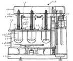
図1には本発明の一実施形態にかかる溶出試験器を側方より見た図が示されている。
図2には本実施形態にかかる溶出試験器をベッセル蓋の上方より見た図が示されている。
本実施形態において、溶出試験器10は、恒温水槽12と、ベッセル14と、ベッセル蓋16と、ノズルホルダ18と、吸引ノズル20と、自動一斉投薬機構(投薬機構)22と、を備える。Hereinafter, a preferred embodiment of the present invention will be described with reference to the drawings.
FIG. 1 shows a side view of a dissolution tester according to an embodiment of the present invention.
FIG. 2 shows a view of the dissolution tester according to the present embodiment as viewed from above the vessel lid.
In the present embodiment, the
ここで、前記恒温水槽12は、横断面が円形のものであり、恒温水24が入れられる。
また前記ベッセル14は、横断面が円形のものであり、試料26及び試験液28を入れられ、所望部分が恒温水槽12内の恒温水24中に沈められる。
前記ベッセル蓋16は、横断面が円形のものであり、ベッセル14の上端開口に設けられ、試験液28の吸引口29を持つ。このベッセル蓋16は、その下端面の外径が上端面の外径よりも小さいテーパ部を持つ。
前記ノズルホルダ18は、ベッセル蓋16の上方で上下動する。
前記吸引ノズル20は、ノズルホルダ18より垂下してノズルホルダ18と共に上下動自在に設けられ、ベッセル蓋16の吸引口29に挿通された状態で、ベッセル14内の試験液28を吸引する。Here, the constant temperature water tank 12 has a circular cross section, and constant temperature water 24 is placed therein.
The
The
The
The
本実施形態において特徴的な自動一斉投薬機構22は、投薬口30と、試料受け32と、操作棒34と、を備える。自動一斉投薬機構22は、所定タイミングで、試料26をベッセル14内に自動的に投薬するためのものとする。
ここで、前記投薬口30は、ベッセル蓋16に設けられ、試料26のベッセル14内への投入のためのものとする。
また前記試料受け32は、ベッセル蓋16に投薬口30を開閉自在に設けられ、投薬口30を閉の状態で試料26をベッセル蓋16に保持し、投薬口30を開の状態で試料26を投薬口30を介してベッセル14内に投薬するためのものとする。
前記操作棒34は、ノズルホルダ18に設けられ、投薬の際は試料受け32と当接し、投薬口30を開の状態とする。The automatic
Here, the
The
The operation rod 34 is provided in the
そして、本実施形態において、投薬の際は、操作棒34をノズルホルダ18と共に下降させ、試料受け32に操作棒34を当接させて操作棒34で試料受け32を下方に押し開き投薬口30を開の状態とし、試料受け32に予めセットしていた試料26を投薬口30を介してベッセル14内に自動的に落下させる。 In the present embodiment, at the time of medication, the operating rod 34 is lowered together with the
<溶出試験器>
なお、本実施形態においては、さらに、ヘッド40と、支持手段42と、水槽蓋44と、蓋移動軸46と、を備える。
前記ヘッド40は、恒温水槽12の上方に配置され、ベース47に対し上下動する。ノズルホルダ18は特定の上下方向位置までヘッド40と共に下降し、該位置から下方ではヘッド40に対しノズルホルダ18が独立して上下動する。
前記支持手段42は、ベース46に対しヘッド40を片持ちの状態で上下動自在に支持する。
前記水槽蓋44は、恒温水槽12の上端開口に設けられ、ベッセル14の本体外径よりも若干大きく、かつベッセル14のフランジ外径よりも若干小さい内径を有する保持穴が設けられ、保持穴にベッセル14の外向きフランジかけることで、恒温水槽12内の恒温水中に対しベッセル14の所望部分を沈めて保持する。
前記蓋移動軸46は、ヘッド下部より垂下してベッセル蓋16の中心に位置決め固定され、ヘッドと共に上下動する。蓋移動軸46は、筒体48と、回転軸49と、を備える。また回転軸の下部にパドル50を備える。
また恒温水槽12には、円形の恒温水槽12の内底に同心円状に円形ヒータ51と、円形の恒温水槽12の内底の中心にパドル等の恒温水攪拌手段52と、を設けている。
このようにして溶出試験器10を構成することにより、溶出試験を安定して行うことができる。<Dissolution tester>
In the present embodiment, a head 40, a support means 42, a
The head 40 is disposed above the constant temperature water bath 12 and moves up and down with respect to the base 47. The
The support means 42 supports the head 40 so as to be movable up and down with respect to the base 46 in a cantilevered state.
The
The lid moving shaft 46 hangs down from the lower part of the head, is positioned and fixed at the center of the
The constant temperature water tank 12 is provided with a concentric circular heater 51 on the inner bottom of the circular constant temperature water tank 12 and a constant temperature water stirring means 52 such as a paddle at the center of the inner bottom of the circular constant temperature water tank 12.
By constituting the
ところで、本発明者らは、溶出試験を安定して行うためには、簡単な構成で、コストをかけず複数のベッセル14への試料の投入を一斉に行うことが非常に重要である点を発見した。
ここで、従来においても投薬を行っており、通常はこれを手作業で行っていた。
しかしながら、このような手作業は面倒であり、また複数のベッセル14間で投入する時間に差が生じる。このため複数のベッセル14間で、溶出時間のばらつきが生じるので、精度の高い溶出試験が行えないことがある。
一方、投薬を容易に行うため、大掛かりな専用機構を設けたのでは、コストがかかり、また大掛かりな専用機構を設けること自体が、溶出試験を不安定にする新たな要因ともなり得る。By the way, in order to perform the dissolution test stably, the inventors of the present invention have a very important point that it is very important to simultaneously put samples into a plurality of
Here, medication is conventionally performed, and this is usually performed manually.
However, such manual work is troublesome, and there is a difference in the time for putting in between the plurality of
On the other hand, providing a large dedicated mechanism for easy dosing is costly, and the provision of a large dedicated mechanism itself can be a new factor that makes the dissolution test unstable.
これに対し、本実施形態にかかる溶出試験器10では、簡単な構成で、コストをかけず複数のベッセル14への試料26の投入を一斉に行うため、溶出試験器10の標準装備の一部を積極的に利用し、自動一斉投薬機構を構成することが非常に重要である。
すなわち、本実施形態では、溶出試験器10の吸引ノズル20の上下機構に、操作棒を設けている。
また溶出試験器10には、試験液28の蒸発防止のためベッセル蓋16を設けているが、このベッセル蓋16に試料受け32を設けている。
このようにして本実施形態においては、溶出試験器10の標準装備を積極的に利用して自動一斉投薬機構を構成することにより、自動一斉投薬のための構成を簡略化し、またコストも抑えている。On the other hand, in the
That is, in this embodiment, the operation bar is provided in the vertical mechanism of the
The
In this way, in the present embodiment, the automatic simultaneous dosing mechanism is configured by actively utilizing the standard equipment of the
以下に、本実施形態の自動一斉投薬機構について、より具体的に説明する。
図3には本実施形態の自動一斉投薬機構の要部が拡大させて示されている。同図(A)は自動一斉投薬機構の近傍を上方より見た図、同図(B)は、同様の自動一斉投薬機構の近傍を側方より見た図である。Below, the automatic simultaneous dosing mechanism of this embodiment is demonstrated more concretely.
FIG. 3 is an enlarged view of a main part of the automatic simultaneous dosing mechanism of the present embodiment. FIG. 4A is a view of the vicinity of the automatic simultaneous dosing mechanism as viewed from above, and FIG. 5B is a view of the vicinity of the same automatic simultaneous dosing mechanism as viewed from the side.
<試料受け>
本実施形態において、前記試料受け32は、開閉扉部54と、棒当接部56と、扉支持部58と、を備える。
ここで、前記開閉扉部54は、試料26が載置された状態で、扉支持部58を軸に蝶番のように回動自在に設けられる。
また前記棒当接部56は、開閉扉部54に設けられ操作棒34と当接し、開閉扉部54と共に回動する。
前記扉支持部58は、例えばバネ等を含み、ベッセル蓋16に対し開閉扉部を蝶番のように回動自在となるように支持する。
そして、投薬の際は、操作棒34で棒当接部56を下方に押して開閉扉部54を開き投薬口30を開の状態とし、開閉扉部54の上に予めセットしておいた試料26が自動的に、投薬口30からベッセル14内に落下する。<Sample receiver>
In the present embodiment, the
Here, the open / close door portion 54 is rotatably provided like a hinge around the door support portion 58 in a state where the
The
The door support portion 58 includes, for example, a spring or the like, and supports the open / close door portion so as to be rotatable like a hinge with respect to the
At the time of medication, the
<操作棒>
また本実施形態において、前記操作棒34はノズルホルダ18からの長さが吸引ノズル20に比較し短い。つまり、本実施形態においては、投薬の際に操作棒34は試料受け32と当接し投薬口30を開の状態とし、かつ吸引ノズル20はベッセル14内底と接触しない上下方向位置にあり、また試験液28の吸引の際、操作棒34は試料受け32と当接せず投薬口30を閉の状態とし、かつ吸引ノズル20はベッセル14内の所望深さで試験液28を吸引可能な上下方向位置にあるように、ノズルホルダ18からの操作棒34の長さが決められていることが好適である。<Operation bar>
In the present embodiment, the operation rod 34 is shorter than the
このような自動一斉投薬機構により、図4に示されるような投薬を行う。なお、同図(A)は溶出試験の開始前の状態、同図(B)は試料26の投薬時(溶出試験の開始時)の状態、同図(C)は試験液28の吸引時の状態である。 With such an automatic simultaneous dosing mechanism, dosing as shown in FIG. 4 is performed. 2A shows the state before the start of the dissolution test, FIG. 2B shows the state when the
<試験開始前>
すなわち、同図(A)に示されるような、溶出試験の開始前の状態では、吸引ノズル20及び操作棒34は、ベッセル14上方に離隔している。試料26は予め開閉扉部54の上にセットされている。<Before test start>
That is, the
<試験開始時>
同図(B)に示されるような投薬時は、吸引ノズル20を通常の吸引位置よりも低い投薬位置まで下げる。操作棒34が棒当接部56に当接し、開閉扉部54を開くと、投薬口30が開口するので、試料26が開閉扉部54から投薬口30を介してベッセル14内に落下する。投薬と同時に溶出試験を開始する。
また試料26の落下後、操作棒34を吸引ノズル20と共に上昇させると、操作棒34が棒当接部56から離隔するので、開閉扉部54がバネ等の扉支持部58の力で閉まり、投薬口30を閉口する。このため、ベッセル14内の試験液28の蒸発を確実に防ぐこともできる。<At the start of the test>
At the time of medication as shown in FIG. 5B, the
When the operating rod 34 is lifted together with the
<試験液吸引時>
そして、溶出試験の開始から規定の時間後、試験液の吸引時は、同図(C)に示されるような吸引ノズル20を通常の吸引位置まで下げる。吸引ノズル20でベッセル14内の試験液28を吸引する。<During test solution suction>
Then, after a specified time from the start of the dissolution test, when the test solution is sucked, the
このような投薬後は、吸引時は勿論、溶出試験中は、操作棒34がベッセル蓋16の試料受け32に届かず、試料受け32を押し下げていないので、投薬口30は閉口したままである。このためベッセル14内の試験液28の蒸発を確実に防ぐこともできる。
このようにして吸引された試験液28を標準溶液とし、後段で溶出率が求められる。After such administration, during the elution test, the operation rod 34 does not reach the
The
このように本実施形態にかかる溶出試験器10によれば、自動一斉投薬機構を、溶出試験器10の標準装備をうまく利用して構成することで、コストをあまりかけることなく、簡単な構成でも、自動的に試料26の複数のベッセル14への一斉投入を同時に行うことができる。
したがって、本実施形態においては、簡単な構成で、溶出試験を安定して行うことができる。As described above, according to the
Therefore, in the present embodiment, the dissolution test can be stably performed with a simple configuration.
<投薬タイミングの認識>
また本実施形態は、以下の点からも、簡単な構成で、溶出試験を安定して行うことができる。
すなわち、試料26を一斉に投入しても、投入タイミングを正確に認識できなければ、規定の溶出時間を管理するのが困難である。
このため本実施形態においては、投入タイミングの正確な認識も非常に重要である。
すなわち、手動で専用投薬機構を操作していたのでは、コンピュータ(PC)または溶出試験器(DT)による試料26の投入タイミングの認識が困難である。このため従来は試料投入時からの溶出時間の管理が困難であったので、規定の溶出時間で、溶出試験を安定して行うのが困難であった。
これに対し、本実施形態は、吸引ノズル20を投下位置まで下げる命令を、コンピュータ(PC)または溶出試験器(DT)により行うことにより、錠剤の投下タイミングを測定プログラムのスタート時と自動的に認識することができる。このため本実施形態は、このような錠剤の投下タイミングに基づく試料投入時からの溶出時間の管理が非常に正確に行えるので、規定の溶出時間で、溶出試験を安定して行うことができる。<Recognition of medication timing>
Moreover, this embodiment can perform a dissolution test stably with a simple structure also from the following points.
That is, it is difficult to manage the prescribed elution time if the loading timing cannot be accurately recognized even when the
For this reason, in this embodiment, accurate recognition of the input timing is also very important.
That is, if the dedicated dosing mechanism is manually operated, it is difficult to recognize the input timing of the
On the other hand, in this embodiment, by giving a command to lower the
<籠>
また本実施形態においては、前記投薬を、より確実に行うため、以下のものを用いることも好ましい。
すなわち、本実施形態において、図5に示されるようなメッシュ状の円筒の籠60を備える。
ここで、前記籠60は、予め試料26が入れられた状態で、試料受け32にセットされる。
そして、試料受け32が開くと、各ベッセル14間で同様にして、試料26が籠60毎、ベッセル14内に落下する。
この結果、本実施形態においては、試料26をそのまま投薬するものに比較し、各ベッセル14間での投薬タイミングをより同一とすることができるので、前記溶出試験を、複数のベッセル14間で、より安定して行うことができる。<籠>
Moreover, in this embodiment, in order to perform the said administration more reliably, it is also preferable to use the following.
That is, in the present embodiment, a mesh-shaped
Here, the
When the
As a result, in the present embodiment, compared to the
<剤形>
前記構成では、試料26の剤形として、錠剤に適用した例について説明したが、そのほか、カプセル、顆粒、粉末等に好適に適用することができる。<Dosage form>
In the above configuration, the example in which the
10 溶出試験器
12 恒温水槽
14 ベッセル
16 ベッセル蓋
18 ノズルホルダ
20 吸引ノズル
22 自動一斉投薬機構(投薬機構)10 Dissolution tester
12 Constant
Claims (4)
Translated fromJapanese溶出試験を行うための試験液を入れるための上端開口を持つ有底の本体を含み、該本体の所望部分が前記恒温水槽内の恒温水中に沈められるベッセルと、
前記ベッセルの上端開口に設けられ、試験液の吸引口を持つベッセル蓋と、
前記ベッセル蓋の上方で上下動するノズルホルダと、
前記ノズルホルダより垂下して該ノズルホルダと共に上下動自在に設けられ、前記ベッセル蓋の吸引口に挿通された状態で前記ベッセル内の試験液を吸引する吸引ノズルと、
所定タイミングで、溶出試験を行う試料を前記ベッセル内に自動的に投薬するための投薬機構と、
を備え、
前記投薬機構は、前記ベッセル蓋に設けられ、試料の前記ベッセル内への投入のための投薬口と、
前記ベッセル蓋に投薬口を開閉自在に設けられ、前記投薬口を閉の状態で試料を該ベッセル蓋に保持し、該投薬口を開の状態で試料を該投薬口を介して前記ベッセル内に投薬するための試料受けと、
前記ノズルホルダに設けられ、投薬の際は、前記試料受けと当接し、前記投薬口を開の状態とする操作棒と、
を備え、前記投薬の際は、前記操作棒を前記ノズルホルダと共に下降させ、該試料受けに該操作棒を当接させて該該操作棒で該試料受けを下方に押し開くことで前記投薬口を開の状態とし、該試料受けに予めセットしていた試料を該投薬口を介して前記ベッセル内に落させることを特徴とする溶出試験器。A constant temperature water tank in which constant temperature water can be placed;
A vessel having a bottomed body having an upper end opening for containing a test solution for performing a dissolution test, wherein a desired portion of the body is submerged in the constant temperature water in the constant temperature water bath;
A vessel lid provided at the upper end opening of the vessel and having a suction port for a test solution;
A nozzle holder that moves up and down above the vessel lid;
A suction nozzle that hangs down from the nozzle holder and is vertically movable together with the nozzle holder, and sucks the test liquid in the vessel in a state of being inserted into the suction port of the vessel lid;
A dosing mechanism for automatically dispensing a sample to be dissolved into the vessel at a predetermined timing;
With
The dosing mechanism is provided on the vessel lid, and a dosing port for loading a sample into the vessel;
A dosing port is provided in the vessel lid so that the dosing port can be opened and closed, the sample is held in the vessel lid with the dosing port closed, and the sample is placed in the vessel through the dosing port with the dosing port open. A sample receiver for dosing;
An operating rod provided in the nozzle holder, in contact with the sample receiver during dosing, and opening the dosing port;
And when dispensing, the operation rod is lowered together with the nozzle holder, the operation rod is brought into contact with the sample receiver, and the sample receiver is pushed downward by the operation rod to open the administration port. The dissolution tester is characterized in that the sample set in the sample receiver is dropped into the vessel through the dosing port.
前記試料受けは、前記ベッセル蓋の投薬口において蝶番のように回動自在に設けられ、試料が載置される開閉扉部と、
前記操作棒と当接し、前記開閉扉部と共に回動する棒当接部と
前記ベッセル蓋に対し前記開閉扉部を蝶番のように回動自在となるように支持する支持部と、
を備え、前記操作棒で前記棒当接部を下方に押すと、該棒当接部と共に前記開閉扉部が回動し前記投薬口を開の状態とし、該開閉扉部に予めセットされていた試料を該投薬口を介して前記ベッセル内に落下させることを特徴とする溶出試験器。The dissolution tester according to claim 1, wherein
The sample receiver is rotatably provided like a hinge at the medication opening of the vessel lid, and an open / close door portion on which the sample is placed,
A rod abutting portion that abuts on the operation rod and rotates together with the opening and closing door portion; a support portion that supports the opening and closing door portion so as to be rotatable like a hinge with respect to the vessel lid;
When the rod abutting portion is pushed downward by the operation rod, the opening / closing door portion rotates together with the rod abutting portion to open the medication opening, and is set in the opening / closing door portion in advance. A dissolution tester, wherein the sample is dropped into the vessel through the dosing port.
前記操作棒は前記ノズルホルダからの長さが前記吸引ノズルに比較し短く、これは、投薬の際、前記操作棒は前記試料受けと当接し前記投薬口を開の状態とし、かつ該吸引ノズルは前記ベッセル内底と接触しない上下方向位置にあり、また試験液の吸引の際、該操作棒は該試料受けと当接せず該投薬口を閉の状態とし、かつ該吸引ノズルは該ベッセル内の試験液を吸引可能な上下方向位置にあるような、該操作棒の長さであることを特徴とする溶出試験器。The dissolution tester according to claim 1 or 2,
The operating rod has a shorter length from the nozzle holder than the suction nozzle, which means that, when dispensing, the operating rod comes into contact with the sample receiver to open the dispensing port, and the suction nozzle Is in a vertical position not in contact with the inner bottom of the vessel, and when the test solution is sucked, the operating rod does not come into contact with the sample receiver and the dosing port is closed, and the suction nozzle is in the vessel An elution tester characterized in that the length of the operation rod is at a vertical position where the test liquid can be sucked.
試料が入れられた状態で前記試料受けにセットされる籠を備え、
投薬の際は、試料を前記籠毎、前記投薬口を介して前記ベッセル内に落下させることを特徴とする溶出試験器。In the dissolution tester according to any one of claims 1 to 3,
A scissors set on the sample receiver in a state where the sample is placed,
A dissolution tester characterized in that a sample is dropped into the vessel through the dosing opening for each sputum during dosing.
Priority Applications (2)
| Application Number | Priority Date | Filing Date | Title |
|---|---|---|---|
| JP2005144172AJP4648083B2 (en) | 2005-05-17 | 2005-05-17 | Dissolution tester |
| US11/383,572US7401533B2 (en) | 2005-05-17 | 2006-05-16 | Dissolution tester |
Applications Claiming Priority (1)
| Application Number | Priority Date | Filing Date | Title |
|---|---|---|---|
| JP2005144172AJP4648083B2 (en) | 2005-05-17 | 2005-05-17 | Dissolution tester |
Publications (2)
| Publication Number | Publication Date |
|---|---|
| JP2006322744Atrue JP2006322744A (en) | 2006-11-30 |
| JP4648083B2 JP4648083B2 (en) | 2011-03-09 |
Family
ID=37447084
Family Applications (1)
| Application Number | Title | Priority Date | Filing Date |
|---|---|---|---|
| JP2005144172AExpired - LifetimeJP4648083B2 (en) | 2005-05-17 | 2005-05-17 | Dissolution tester |
Country Status (2)
| Country | Link |
|---|---|
| US (1) | US7401533B2 (en) |
| JP (1) | JP4648083B2 (en) |
Cited By (3)
| Publication number | Priority date | Publication date | Assignee | Title |
|---|---|---|---|---|
| KR100917351B1 (en) | 2009-05-29 | 2009-09-16 | 정수영 | Eluent with increased durability and reliable operation |
| JP2015102433A (en)* | 2013-11-26 | 2015-06-04 | 柴田科学株式会社 | Chemical supply device and water flow type fish testing apparatus |
| JP2022062327A (en)* | 2020-10-08 | 2022-04-20 | 学校法人立命館 | Tester |
Families Citing this family (13)
| Publication number | Priority date | Publication date | Assignee | Title |
|---|---|---|---|---|
| US7585465B2 (en)* | 2006-06-15 | 2009-09-08 | Logan Instruments Corp. | Pharmaceutical product release rate testing device |
| AU2008222833A1 (en)* | 2007-03-08 | 2008-09-12 | Smithkline Beecham Corporation | Pharmaceutical analysis apparatus and method |
| US20080311613A1 (en)* | 2007-06-14 | 2008-12-18 | The Government Of The U.S.A. As Represented By The Secretary Of The Dept. Of Health & Human Services | Artificial skin surface film liquids |
| US7687268B2 (en)* | 2007-07-25 | 2010-03-30 | Medtronic Minimed, Inc. | Apparatuses and media for drug elution and methods for making and using them |
| US20090155920A1 (en)* | 2007-11-12 | 2009-06-18 | Symyx Technologies, Inc. | High throughput dissolution and precipitation apparatus and method |
| EP2227683A1 (en)* | 2007-12-06 | 2010-09-15 | Pain Therapeutics, Inc. | Dissolution test equipment and methods for testing |
| US7790461B2 (en)* | 2007-12-28 | 2010-09-07 | Medtronic Minimed, Inc. | Nano-emulsion technology for drug elution |
| US8372646B1 (en) | 2009-12-21 | 2013-02-12 | Medtronic Minimed, Inc. | Terpene media compositions for eluting compounds from matrices and methods for making and using them |
| US8434378B2 (en) | 2010-04-12 | 2013-05-07 | Distek, Inc. | Dissolution-testing vessel cover |
| USD688963S1 (en)* | 2012-12-03 | 2013-09-03 | Royal A. Hanson | Sampling machine |
| CN109012421B (en)* | 2018-08-30 | 2021-01-29 | 江苏三阳环保工程有限公司 | Vacuum stirring equipment for battery production |
| CN109046097B (en)* | 2018-08-30 | 2021-03-12 | 丁柳朋 | Vacuum stirring equipment is used in battery production convenient to get material |
| CN109012420B (en)* | 2018-08-30 | 2020-10-02 | 丁柳朋 | Get convenient vacuum mixing equipment for battery production of material |
Citations (10)
| Publication number | Priority date | Publication date | Assignee | Title |
|---|---|---|---|---|
| JPH05164761A (en)* | 1991-12-18 | 1993-06-29 | Dainippon Seiki:Kk | Automatic preprocessor for chemical analysis |
| JP2966065B2 (en)* | 1990-08-20 | 1999-10-25 | 株式会社大日本精機 | Dissolution test equipment |
| US6170980B1 (en)* | 1999-04-09 | 2001-01-09 | Source For Automation, Inc. | Automated tablet dissolution apparatus |
| US6308584B1 (en)* | 1999-05-11 | 2001-10-30 | Sotax Ag | Process, cartridge and device for introducing a particulate material into a liquid |
| JP2004519673A (en)* | 2001-02-28 | 2004-07-02 | ヴァリアン インコーポレーテッド | Dissolution test equipment |
| JP2004537146A (en)* | 2001-07-23 | 2004-12-09 | ヴァリアン インコーポレーテッド | Heating element, container heating system and container heating method using the same |
| JP2005514587A (en)* | 2001-10-11 | 2005-05-19 | エラン・フアルマ・インターナシヨナル・リミテツド | Apparatus and method for simultaneously monitoring active release and physical appearance of solid dosage form pharmaceuticals |
| US7024955B2 (en)* | 2003-03-01 | 2006-04-11 | Symyx Technologies, Inc. | Methods and systems for dissolution testing |
| JP2006118985A (en)* | 2004-10-21 | 2006-05-11 | Shimadzu Corp | Liquid chromatographic dissolution test equipment |
| JP2007519934A (en)* | 2004-01-30 | 2007-07-19 | アンドルックス ラボズ リミテッド ライアビリティ カンパニー | Tablet holder device and method for immersion testing |
Family Cites Families (1)
| Publication number | Priority date | Publication date | Assignee | Title |
|---|---|---|---|---|
| JP2000283977A (en) | 1999-03-31 | 2000-10-13 | Shimadzu Corp | Tablet dissolution tester |
- 2005
- 2005-05-17JPJP2005144172Apatent/JP4648083B2/ennot_activeExpired - Lifetime
- 2006
- 2006-05-16USUS11/383,572patent/US7401533B2/ennot_activeExpired - Fee Related
Patent Citations (10)
| Publication number | Priority date | Publication date | Assignee | Title |
|---|---|---|---|---|
| JP2966065B2 (en)* | 1990-08-20 | 1999-10-25 | 株式会社大日本精機 | Dissolution test equipment |
| JPH05164761A (en)* | 1991-12-18 | 1993-06-29 | Dainippon Seiki:Kk | Automatic preprocessor for chemical analysis |
| US6170980B1 (en)* | 1999-04-09 | 2001-01-09 | Source For Automation, Inc. | Automated tablet dissolution apparatus |
| US6308584B1 (en)* | 1999-05-11 | 2001-10-30 | Sotax Ag | Process, cartridge and device for introducing a particulate material into a liquid |
| JP2004519673A (en)* | 2001-02-28 | 2004-07-02 | ヴァリアン インコーポレーテッド | Dissolution test equipment |
| JP2004537146A (en)* | 2001-07-23 | 2004-12-09 | ヴァリアン インコーポレーテッド | Heating element, container heating system and container heating method using the same |
| JP2005514587A (en)* | 2001-10-11 | 2005-05-19 | エラン・フアルマ・インターナシヨナル・リミテツド | Apparatus and method for simultaneously monitoring active release and physical appearance of solid dosage form pharmaceuticals |
| US7024955B2 (en)* | 2003-03-01 | 2006-04-11 | Symyx Technologies, Inc. | Methods and systems for dissolution testing |
| JP2007519934A (en)* | 2004-01-30 | 2007-07-19 | アンドルックス ラボズ リミテッド ライアビリティ カンパニー | Tablet holder device and method for immersion testing |
| JP2006118985A (en)* | 2004-10-21 | 2006-05-11 | Shimadzu Corp | Liquid chromatographic dissolution test equipment |
Cited By (4)
| Publication number | Priority date | Publication date | Assignee | Title |
|---|---|---|---|---|
| KR100917351B1 (en) | 2009-05-29 | 2009-09-16 | 정수영 | Eluent with increased durability and reliable operation |
| JP2015102433A (en)* | 2013-11-26 | 2015-06-04 | 柴田科学株式会社 | Chemical supply device and water flow type fish testing apparatus |
| JP2022062327A (en)* | 2020-10-08 | 2022-04-20 | 学校法人立命館 | Tester |
| JP7510165B2 (en) | 2020-10-08 | 2024-07-03 | 学校法人立命館 | Testing Equipment |
Also Published As
| Publication number | Publication date |
|---|---|
| US20060260421A1 (en) | 2006-11-23 |
| US7401533B2 (en) | 2008-07-22 |
| JP4648083B2 (en) | 2011-03-09 |
Similar Documents
| Publication | Publication Date | Title |
|---|---|---|
| US7401533B2 (en) | Dissolution tester | |
| US9255865B2 (en) | Integrated dissolution processing and sample transfer system | |
| JP2008216271A (en) | Automatic chemistry analyzer with sample cup plug piercing assembly | |
| JP6774151B2 (en) | Automatic analyzer | |
| US20160187365A1 (en) | Automated Analyzer and Method for Lifting and Lowering Rod-Like Member in Automated Analyzer | |
| WO2013168559A1 (en) | Sampling device | |
| US20060159587A1 (en) | Automated clinical analyzer with dual level storage and access | |
| JP2012523555A (en) | Gel card filling device including an ionization device | |
| JPWO2017018214A1 (en) | Automatic analyzer | |
| JP3687019B2 (en) | Sampling device | |
| JP3776235B2 (en) | Specimen container support device for specimen testing equipment | |
| JP2005127896A (en) | Sample sampling apparatus and sampling method for blood | |
| JP2524474B2 (en) | Non-contact automatic mixing method of reaction mixture in analysis unit | |
| EP3425407B1 (en) | Automatic analysis device | |
| JPWO2009090989A1 (en) | Reagent container | |
| JP6381917B2 (en) | Automatic analyzer and reagent dispensing method | |
| JP6554301B2 (en) | Dispensing device, automatic analyzer and dispensing method | |
| JP6815801B2 (en) | Automatic analyzer | |
| JP4804694B2 (en) | Method for mixing liquid in a container and container for carrying out the method | |
| JP2005127895A (en) | Sampling tube cleaning method in blood sample sampling mechanism | |
| JP3310380B2 (en) | Dispensing device | |
| JP4262553B2 (en) | Desktop liquid content dispensing device | |
| JP7105112B2 (en) | Dispensing unit, automatic analyzer, and liquid level detection judgment method | |
| JP2011153936A (en) | Reagent container | |
| JPH10104135A (en) | Method for analyzing gas component in head space of can container and apparatus used therefor |
Legal Events
| Date | Code | Title | Description |
|---|---|---|---|
| A621 | Written request for application examination | Free format text:JAPANESE INTERMEDIATE CODE: A621 Effective date:20080428 | |
| TRDD | Decision of grant or rejection written | ||
| A01 | Written decision to grant a patent or to grant a registration (utility model) | Free format text:JAPANESE INTERMEDIATE CODE: A01 Effective date:20101124 | |
| A01 | Written decision to grant a patent or to grant a registration (utility model) | Free format text:JAPANESE INTERMEDIATE CODE: A01 | |
| A61 | First payment of annual fees (during grant procedure) | Free format text:JAPANESE INTERMEDIATE CODE: A61 Effective date:20101209 | |
| FPAY | Renewal fee payment (event date is renewal date of database) | Free format text:PAYMENT UNTIL: 20131217 Year of fee payment:3 | |
| R150 | Certificate of patent or registration of utility model | Free format text:JAPANESE INTERMEDIATE CODE: R150 Ref document number:4648083 Country of ref document:JP Free format text:JAPANESE INTERMEDIATE CODE: R150 | |
| R250 | Receipt of annual fees | Free format text:JAPANESE INTERMEDIATE CODE: R250 | |
| R250 | Receipt of annual fees | Free format text:JAPANESE INTERMEDIATE CODE: R250 | |
| R250 | Receipt of annual fees | Free format text:JAPANESE INTERMEDIATE CODE: R250 | |
| R250 | Receipt of annual fees | Free format text:JAPANESE INTERMEDIATE CODE: R250 | |
| R250 | Receipt of annual fees | Free format text:JAPANESE INTERMEDIATE CODE: R250 | |
| R250 | Receipt of annual fees | Free format text:JAPANESE INTERMEDIATE CODE: R250 | |
| R250 | Receipt of annual fees | Free format text:JAPANESE INTERMEDIATE CODE: R250 | |
| R250 | Receipt of annual fees | Free format text:JAPANESE INTERMEDIATE CODE: R250 | |
| R250 | Receipt of annual fees | Free format text:JAPANESE INTERMEDIATE CODE: R250 | |
| R250 | Receipt of annual fees | Free format text:JAPANESE INTERMEDIATE CODE: R250 | |
| R250 | Receipt of annual fees | Free format text:JAPANESE INTERMEDIATE CODE: R250 | |
| R250 | Receipt of annual fees | Free format text:JAPANESE INTERMEDIATE CODE: R250 | |
| EXPY | Cancellation because of completion of term |