JP2006321027A - Master / slave manipulator system and its operation input device - Google Patents
Master / slave manipulator system and its operation input deviceDownload PDFInfo
- Publication number
- JP2006321027A JP2006321027AJP2005147786AJP2005147786AJP2006321027AJP 2006321027 AJP2006321027 AJP 2006321027AJP 2005147786 AJP2005147786 AJP 2005147786AJP 2005147786 AJP2005147786 AJP 2005147786AJP 2006321027 AJP2006321027 AJP 2006321027A
- Authority
- JP
- Japan
- Prior art keywords
- manipulator
- power transmission
- input device
- operation input
- arm
- Prior art date
- Legal status (The legal status is an assumption and is not a legal conclusion. Google has not performed a legal analysis and makes no representation as to the accuracy of the status listed.)
- Pending
Links
Images


Classifications
- B—PERFORMING OPERATIONS; TRANSPORTING
- B25—HAND TOOLS; PORTABLE POWER-DRIVEN TOOLS; MANIPULATORS
- B25J—MANIPULATORS; CHAMBERS PROVIDED WITH MANIPULATION DEVICES
- B25J3/00—Manipulators of leader-follower type, i.e. both controlling unit and controlled unit perform corresponding spatial movements
- B25J3/04—Manipulators of leader-follower type, i.e. both controlling unit and controlled unit perform corresponding spatial movements involving servo mechanisms
- A—HUMAN NECESSITIES
- A61—MEDICAL OR VETERINARY SCIENCE; HYGIENE
- A61B—DIAGNOSIS; SURGERY; IDENTIFICATION
- A61B34/00—Computer-aided surgery; Manipulators or robots specially adapted for use in surgery
- A61B34/30—Surgical robots
- A61B34/37—Leader-follower robots
- A—HUMAN NECESSITIES
- A61—MEDICAL OR VETERINARY SCIENCE; HYGIENE
- A61B—DIAGNOSIS; SURGERY; IDENTIFICATION
- A61B34/00—Computer-aided surgery; Manipulators or robots specially adapted for use in surgery
- A61B34/70—Manipulators specially adapted for use in surgery
- B—PERFORMING OPERATIONS; TRANSPORTING
- B25—HAND TOOLS; PORTABLE POWER-DRIVEN TOOLS; MANIPULATORS
- B25J—MANIPULATORS; CHAMBERS PROVIDED WITH MANIPULATION DEVICES
- B25J13/00—Controls for manipulators
- B25J13/02—Hand grip control means
- B—PERFORMING OPERATIONS; TRANSPORTING
- B25—HAND TOOLS; PORTABLE POWER-DRIVEN TOOLS; MANIPULATORS
- B25J—MANIPULATORS; CHAMBERS PROVIDED WITH MANIPULATION DEVICES
- B25J19/00—Accessories fitted to manipulators, e.g. for monitoring, for viewing; Safety devices combined with or specially adapted for use in connection with manipulators
- B25J19/0004—Braking devices
- B—PERFORMING OPERATIONS; TRANSPORTING
- B25—HAND TOOLS; PORTABLE POWER-DRIVEN TOOLS; MANIPULATORS
- B25J—MANIPULATORS; CHAMBERS PROVIDED WITH MANIPULATION DEVICES
- B25J9/00—Programme-controlled manipulators
- B25J9/16—Programme controls
- B25J9/1674—Programme controls characterised by safety, monitoring, diagnostic
- B25J9/1676—Avoiding collision or forbidden zones
- B—PERFORMING OPERATIONS; TRANSPORTING
- B25—HAND TOOLS; PORTABLE POWER-DRIVEN TOOLS; MANIPULATORS
- B25J—MANIPULATORS; CHAMBERS PROVIDED WITH MANIPULATION DEVICES
- B25J9/00—Programme-controlled manipulators
- B25J9/16—Programme controls
- B25J9/1679—Programme controls characterised by the tasks executed
- B25J9/1689—Teleoperation
- A—HUMAN NECESSITIES
- A61—MEDICAL OR VETERINARY SCIENCE; HYGIENE
- A61B—DIAGNOSIS; SURGERY; IDENTIFICATION
- A61B34/00—Computer-aided surgery; Manipulators or robots specially adapted for use in surgery
- A61B34/30—Surgical robots
- A—HUMAN NECESSITIES
- A61—MEDICAL OR VETERINARY SCIENCE; HYGIENE
- A61B—DIAGNOSIS; SURGERY; IDENTIFICATION
- A61B90/00—Instruments, implements or accessories specially adapted for surgery or diagnosis and not covered by any of the groups A61B1/00 - A61B50/00, e.g. for luxation treatment or for protecting wound edges
- A61B90/36—Image-producing devices or illumination devices not otherwise provided for
- A61B90/361—Image-producing devices, e.g. surgical cameras
- G—PHYSICS
- G05—CONTROLLING; REGULATING
- G05B—CONTROL OR REGULATING SYSTEMS IN GENERAL; FUNCTIONAL ELEMENTS OF SUCH SYSTEMS; MONITORING OR TESTING ARRANGEMENTS FOR SUCH SYSTEMS OR ELEMENTS
- G05B2219/00—Program-control systems
- G05B2219/30—Nc systems
- G05B2219/39—Robotics, robotics to robotics hand
- G05B2219/39088—Inhibit movement in one axis if collision danger
- G—PHYSICS
- G05—CONTROLLING; REGULATING
- G05B—CONTROL OR REGULATING SYSTEMS IN GENERAL; FUNCTIONAL ELEMENTS OF SUCH SYSTEMS; MONITORING OR TESTING ARRANGEMENTS FOR SUCH SYSTEMS OR ELEMENTS
- G05B2219/00—Program-control systems
- G05B2219/30—Nc systems
- G05B2219/39—Robotics, robotics to robotics hand
- G05B2219/39114—Hand eye cooperation, active camera on first arm follows movement of second arm
- G—PHYSICS
- G05—CONTROLLING; REGULATING
- G05B—CONTROL OR REGULATING SYSTEMS IN GENERAL; FUNCTIONAL ELEMENTS OF SUCH SYSTEMS; MONITORING OR TESTING ARRANGEMENTS FOR SUCH SYSTEMS OR ELEMENTS
- G05B2219/00—Program-control systems
- G05B2219/30—Nc systems
- G05B2219/40—Robotics, robotics mapping to robotics vision
- G05B2219/40161—Visual display of machining, operation, remote viewing
- G—PHYSICS
- G05—CONTROLLING; REGULATING
- G05B—CONTROL OR REGULATING SYSTEMS IN GENERAL; FUNCTIONAL ELEMENTS OF SUCH SYSTEMS; MONITORING OR TESTING ARRANGEMENTS FOR SUCH SYSTEMS OR ELEMENTS
- G05B2219/00—Program-control systems
- G05B2219/30—Nc systems
- G05B2219/40—Robotics, robotics mapping to robotics vision
- G05B2219/40181—Operator can fine position in small area, free, but if contact, force feedback
- G—PHYSICS
- G05—CONTROLLING; REGULATING
- G05B—CONTROL OR REGULATING SYSTEMS IN GENERAL; FUNCTIONAL ELEMENTS OF SUCH SYSTEMS; MONITORING OR TESTING ARRANGEMENTS FOR SUCH SYSTEMS OR ELEMENTS
- G05B2219/00—Program-control systems
- G05B2219/30—Nc systems
- G05B2219/40—Robotics, robotics mapping to robotics vision
- G05B2219/40212—Two-way clutch for joint, prevents movement in unallowable direction
- G—PHYSICS
- G05—CONTROLLING; REGULATING
- G05B—CONTROL OR REGULATING SYSTEMS IN GENERAL; FUNCTIONAL ELEMENTS OF SUCH SYSTEMS; MONITORING OR TESTING ARRANGEMENTS FOR SUCH SYSTEMS OR ELEMENTS
- G05B2219/00—Program-control systems
- G05B2219/30—Nc systems
- G05B2219/40—Robotics, robotics mapping to robotics vision
- G05B2219/40478—Graphic display of work area of robot, forbidden, permitted zone
- G—PHYSICS
- G05—CONTROLLING; REGULATING
- G05B—CONTROL OR REGULATING SYSTEMS IN GENERAL; FUNCTIONAL ELEMENTS OF SUCH SYSTEMS; MONITORING OR TESTING ARRANGEMENTS FOR SUCH SYSTEMS OR ELEMENTS
- G05B2219/00—Program-control systems
- G05B2219/30—Nc systems
- G05B2219/45—Nc applications
- G05B2219/45118—Endoscopic, laparoscopic manipulator
Landscapes
- Engineering & Computer Science (AREA)
- Robotics (AREA)
- Health & Medical Sciences (AREA)
- Mechanical Engineering (AREA)
- Life Sciences & Earth Sciences (AREA)
- Surgery (AREA)
- Heart & Thoracic Surgery (AREA)
- Biomedical Technology (AREA)
- Nuclear Medicine, Radiotherapy & Molecular Imaging (AREA)
- Medical Informatics (AREA)
- Molecular Biology (AREA)
- Animal Behavior & Ethology (AREA)
- General Health & Medical Sciences (AREA)
- Public Health (AREA)
- Veterinary Medicine (AREA)
- Manipulator (AREA)
Abstract
Translated fromJapaneseDescription
Translated fromJapanese本発明は、マスタ・スレーブ式マニピュレータシステム及びその操作入力装置に関するものである。 The present invention relates to a master / slave manipulator system and its operation input device.
操作入力装置を操作者が操作し、その操作に従ってマニピュレータが動作するマスタ・スレーブ式マニピュレータシステムが数多く開発されている。 Many master / slave manipulator systems in which an operation input device is operated by an operator and a manipulator operates according to the operation have been developed.
しかし、通常のマスタ・スレーブ式マニピュレータでは、マニピュレータアームの動作範囲内で避けて通らねばならない障害物や侵入してはいけない危険領域などがあったとしても、操作入力装置をその障害物や危険領域に対応する位置に動かすと、マニピュレータアームは障害物に当たってしまったり危険領域に侵入してしまったりするものであった。 However, with a normal master / slave manipulator, even if there are obstacles that must be avoided within the operating range of the manipulator arm or dangerous areas that should not be entered, the operation input device must be connected to the obstacle or dangerous area. When moved to a position corresponding to, the manipulator arm hits an obstacle or enters a dangerous area.
このような問題を解決するために、特開平7−124876号公報(特許文献1)では、マニピュレータアームにとって障害物となる位置と対応する操作入力装置の動作範囲に位置規制部材を配置し、マニピュレータアームを動かしてはいけない領域へは操作入力装置を動かすことができないようにしている。 In order to solve such a problem, Japanese Patent Application Laid-Open No. 7-1224876 (Patent Document 1) arranges a position regulating member in an operation range of an operation input device corresponding to a position that becomes an obstacle for a manipulator arm, and The operation input device cannot be moved to an area where the arm should not be moved.
また、特開2004−22328号公報(特許文献2)では、あらかじめ診断装置によってマニピュレータアームの動作範囲情報を取得し、治療のためにマニピュレータアームが動いてもよい領域を定め、操作者がマニピュレータアームを設定領域外に動作させようとしたとき、操作入力装置の可動範囲を操作入力装置に配置したモータにより制限し、マニピュレータアームの設定領域外への動作を制限するようにしている。 In Japanese Patent Application Laid-Open No. 2004-22328 (Patent Document 2), the operating range information of the manipulator arm is acquired in advance by a diagnostic device, an area where the manipulator arm may move for treatment is determined, and the operator operates the manipulator arm. When an attempt is made to operate outside the setting area, the movable range of the operation input device is limited by a motor arranged in the operation input device, and the operation of the manipulator arm outside the setting area is limited.
また、特開平11−333764号公報(特許文献3)では、アームが対象物に接触した際に、動力伝達可変装置を用いて操作入力装置に力覚を提示し抵抗を感じさせるようにしている。 Further, in Japanese Patent Application Laid-Open No. 11-333964 (Patent Document 3), when an arm contacts an object, a force sense is presented to the operation input device by using a power transmission variable device so as to feel resistance. .
従来のマスタ・スレーブ式マニピュレータでは、マニピュレータアームが動いてはいけない領域に操作入力装置を動かせなくするために、操作入力装置にアクチュエータを設置し、操作者に力を返すことによって動作の制限を実現していた。しかし、操作入力装置にアクチュエータを設置すると、操作入力装置が大型化する上、故障などによって操作者に過大な力が生じる場合がある。 In conventional master / slave manipulators, in order to prevent the operation input device from moving in the area where the manipulator arm should not move, an actuator is installed in the operation input device, and the operation is limited by returning force to the operator. Was. However, when an actuator is installed in the operation input device, the operation input device becomes large and an excessive force may be generated on the operator due to a failure or the like.
また、操作入力装置において、アクチュエータを用いて動作範囲や壁を力覚的に表現すると、壁を感じる部分と自由に動作できる部分での領域において、制御が複雑で振動的な振る舞いが生じやすいという問題もある。 Also, in the operation input device, if the motion range and wall are expressed forcefully using an actuator, the control is complicated and vibrational behavior is likely to occur in the area where the wall is felt and the part where the wall can be freely operated. There is also a problem.
また、ノイズなどが問題となる環境では、アクチュエータとして通常のモータを用いることが困難な場合もある。例えば、診断装置としてMRI装置を用いるような手術支援マニピュレータシステムにおいては、モータを用いた操作入力装置はMRI装置とノイズ干渉が生じるために利用することが困難である。 Further, in an environment where noise or the like becomes a problem, it may be difficult to use a normal motor as an actuator. For example, in a surgical support manipulator system using an MRI apparatus as a diagnostic apparatus, it is difficult to use an operation input apparatus using a motor because noise interference occurs with the MRI apparatus.
なお、特許文献1は、操作入力装置に位置規制部材と接触子を物理的に配置して操作入力装置の動作範囲を制限するため、モータを用いる必要はないが、時々刻々障害物の位置や動作可能範囲が変化する場合には対応が難しい。 Note that Patent Document 1 does not require the use of a motor in order to limit the operation range of the operation input device by physically arranging the position restricting member and the contact on the operation input device. It is difficult to respond when the operable range changes.
特許文献2は、マニピュレータアームが動作を可能とする範囲の設定方法についてなされたものであり、操作入力装置の可動範囲を制限するための方法としてはモータを用いることしか考慮されていない。 Patent Document 2 is a method for setting a range in which the manipulator arm can operate, and only considers using a motor as a method for limiting the movable range of the operation input device.
特許文献3は、対象物にスレーブアームが接触した際の操作入力装置での力覚提示についてなされたものであり、障害物や危険領域の回避を目的としたものでない。また、対象物と接触していない動作は動力伝達可変装置を用いてモータの影響を受けない機構となっているが、マニピュレータが対象物に接触した際にはモータによる動力を用いて力覚を提示するものである。 Japanese Patent Laid-Open No. 2004-228561 has been made about force sense presentation by an operation input device when a slave arm contacts an object, and is not intended to avoid an obstacle or a dangerous area. In addition, the operation that is not in contact with the object is a mechanism that is not affected by the motor using the power transmission variable device, but when the manipulator comes into contact with the object, the haptic is sensed using the power of the motor. It is to be presented.
本発明の目的は、操作入力装置にモータを用いることなく障害物や動作範囲の制限を力覚的に提示することが可能で、信頼性に優れ小型で操作性の良いマスタ・スレーブ式マニピュレータシステム及びその操作入力装置を提供することにある。 An object of the present invention is to provide a master-slave manipulator system that can forcefully present obstacles and the limitation of the operation range without using a motor for the operation input device, and is small, reliable, and easy to operate. And an operation input device thereof.
前述の目的を達成するための本発明の第1の態様は、アームを有するマニピュレータと、前記マニピュレータのアームを動かす操作入力装置と、前記マニピュレータ及び前記操作入力装置を制御するコントローラとを備えたマスタ・スレーブ式マニピュレータシステムにおいて、前記操作入力装置はその関節に動力伝達の切断と動力伝達を接続してその動力伝達接続方向を選択可能な動作方向制限切替機構を備えたものである。 A first aspect of the present invention for achieving the above object is a master including a manipulator having an arm, an operation input device that moves the arm of the manipulator, and a controller that controls the manipulator and the operation input device. In the slave type manipulator system, the operation input device is provided with an operation direction restriction switching mechanism capable of selecting the power transmission connection direction by connecting the power transmission cutting and power transmission to the joint.
係る本発明の第1の態様におけるより好ましい具体的構成例は次の通りである。
(1)前記マニピュレータのアームの動作範囲内の幾何学的な情報や障害物情報を取得可能なセンサあるいは診断装置を有し、前記センサあるいは前記診断装置で検出した前記マニピュレータのアームの動作範囲内の幾何学的な情報や障害物情報に基づいて、前記マニピュレータのアームが動作してもよい領域を設定する手段を備え、前記コントローラは、前記操作入力装置によって前記マニピュレータのアームが動作してはいけない領域に前記マニピュレータのアームを操作しようとした時、前記操作入力装置の各関節に配置した動力伝達の切断と動力伝達接続方向を選択できる機構により、前記マニピュレータのアームが動いてはいけない領域に前記操作入力装置を操作することを制限すること。
(2)前記操作入力装置の各関節に配置した動力伝達の切断と動力伝達接続方向を選択できる機構が二方向クラッチと3点ポジショナソレノイド及びラックアンドピニオンを用いた直動関節機構であること。
(3)前記操作入力装置の各関節に配置した動力伝達の切断と動力伝達接続方向を選択できる機構が二方向クラッチと3点ポジショナソレノイド及び関節を構成する2つのリンクを用いた回転関節機構であること。
(4)前記操作入力装置は、前記動力伝達の切断と動力伝達接続方向を選択できると共に把持開閉の大きさを任意制限可能な把持開閉機構を備えたこと。
(5)前記マニピュレータのアームの動作範囲内の幾何学的な情報を取得する診断装置としてMRI装置を用いたこと。
(6)前記マニピュレータのアームの動作範囲内の幾何学的な情報を取得する診断装置としてCT装置であること。
(7)前記コントローラは前記動作方向制限切替機構の選択を制御して前記マニピュレータのアームの動作範囲を制限するように構成されていること。
(8)前記コントローラは、前記動力伝達の切断と動力伝達接続方向を選択して接続を細かく切替えることにより、前記マニピュレータのアームが対象物に接触した際の力覚を提示するように構成されていること。A more preferable specific configuration example in the first aspect of the present invention is as follows.
(1) A sensor or diagnostic device capable of acquiring geometric information and obstacle information within the operating range of the manipulator arm, and within the operating range of the manipulator arm detected by the sensor or the diagnostic device. Means for setting an area where the arm of the manipulator may operate based on geometric information and obstacle information of the controller, and the controller is configured such that the arm of the manipulator is operated by the operation input device. When the manipulator arm is to be operated in a region that should not be operated, the mechanism that can select the power transmission disconnection and the power transmission connection direction arranged in each joint of the operation input device, to the region where the manipulator arm should not move Restricting operation of the operation input device.
(2) The mechanism capable of cutting the power transmission and selecting the power transmission connection direction disposed at each joint of the operation input device is a linear motion joint mechanism using a two-way clutch, a three-point positioner solenoid, and a rack and pinion.
(3) A mechanism capable of selecting a power transmission disconnection and a power transmission connection direction arranged at each joint of the operation input device is a rotary joint mechanism using a two-way clutch, a three-point positioner solenoid, and two links constituting the joint. There is.
(4) The operation input device includes a grip opening / closing mechanism that can select a power transmission disconnection and a power transmission connection direction and can arbitrarily limit the size of the grip opening / closing.
(5) An MRI apparatus is used as a diagnostic apparatus for acquiring geometric information within the operating range of the arm of the manipulator.
(6) A CT apparatus as a diagnostic apparatus for acquiring geometric information within the operating range of the arm of the manipulator.
(7) The controller is configured to limit the operation range of the arm of the manipulator by controlling selection of the operation direction restriction switching mechanism.
(8) The controller is configured to present a sense of force when the arm of the manipulator comes into contact with an object by selecting cutting of the power transmission and a power transmission connection direction and switching the connection finely. Being.
また、本発明の第2の態様は、マスタ・スレーブ式マニピュレータシステムにおけるマニピュレータのアームを動かす操作入力装置において、その関節に動力伝達の切断と動力伝達を接続してその動力伝達接続方向を選択可能な動作方向制限切替機構を備えたものである。 Further, according to the second aspect of the present invention, in the operation input device for moving the arm of the manipulator in the master / slave manipulator system, the power transmission connection direction can be selected by connecting the power transmission disconnection and the power transmission to the joint. This is provided with a simple operation direction restriction switching mechanism.
本発明によれば、操作入力装置にモータを用いることなく障害物や動作範囲の制限を力覚的に提示することが可能で、信頼性に優れ小型で操作性の良いマスタ・スレーブ式マニピュレータシステム及びその操作入力装置を提供することができる。 According to the present invention, a master / slave manipulator system capable of happily presenting an obstacle and a limitation of an operation range without using a motor for an operation input device, having a small size and excellent operability. And its operation input device.
以下、本発明の一実施形態について図1から図7を用いて説明する。 Hereinafter, an embodiment of the present invention will be described with reference to FIGS.
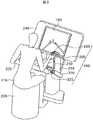
図1は本発明の一実施形態のマスタ・スレーブ式マニピュレータシステムの全体構成を示す概念図である。本実施形態のマニピュレータシステムは手術支援システムとして用いられた例である。 FIG. 1 is a conceptual diagram showing the overall configuration of a master / slave manipulator system according to an embodiment of the present invention. The manipulator system of this embodiment is an example used as a surgery support system.
操作者である術者170は、第1のマニピュレータ110が保持する内視鏡125によって映し出される術具135を参照しながら、操作入力装置190の入力インターフェース165を使って、第2のマニピュレータ130の先端に位置する術具135を操作することができる。参照モニタ100に映し出される画像は、第1のマニピュレータ110が保持する内視鏡125によって患者140の患部を撮像したものであり、通常、患部と共に術具135も内視鏡125の視野に入っている。なお、第1のマニピュレータ110も第2のマニピュレータ130と同様に操作入力装置190の入力インターフェース165を使って動かすことができる。 An
患者140の患部の情報は手術前あるいは手術中に診断装置120により取得され、その情報は位置情報統合コントローラ115に集められる。位置情報統合コントローラ115に取得された患部情報に対し、入力インターフェース116あるいは操作入力装置190の入力インターフェース165により、マニピュレータ110、130が動作してもよい安全領域や、マニピュレータ110、130が動いてはいけない危険領域などを入力する。安全領域(動作可能領域)や危険領域などの情報は、コンバータ105を通して内視鏡125の画像上に重ね合わせて参照モニタ100に提示可能である。 Information on the affected area of the
マニピュレータ110、130の情報はスレーブコントローラ145に集められ、マニピュレータ110、130の位置姿勢などの情報は位置情報統合コントローラ115に送られる。位置情報統合コントローラ115は、設定した安全領域や危険領域などの情報とマニピュレータ110、130の現在位置の情報との比較を行い、マニピュレータ110、130が安全領域から外れそうになるあるいは危険領域に入り込もうとすると、マニピュレータ110、130が動いてはいけない方向を算出し、その情報をスレーブコントローラ145に送信する。スレーブコントローラ145はその情報をマスタコントローラ150に送信する。 Information on the
マスタコントローラ150は、マニピュレータ110、130が動いてはいけない方向に対応する操作入力装置190の一つ以上の関節175において、ソレノイド185を駆動することにより、二方向クラッチ180の動力伝達を接続し、操作入力装置190の入力インターフェース165を、マニピュレータ110、130が動いてはいけない方向には動かせないように拘束する。 The
通常の操作入力時は、各関節175に取り付けられている二方向クラッチ180はソレノイド185によって動力伝達が切断された状態になっており、術者170は入力インターフェース165を自由に動かすことができる。各関節175にはエンコーダやポテンショメータなどのセンサ155が設置されており、センサ155によって取得された関節移動量情報はマスタコントローラ150に送られる。マスタコントローラ150は、これら関節移動量情報を基に、操作者170がマニピュレータ110、130を動かしたい方向・姿勢量を計算し、スレーブコントローラ145に情報を送信する。スレーブコントローラ145は、マニピュレータ110、130の逆運動学を計算し、マニピュレータ110、130の各関節を駆動し、操作者170が意図した動きをマニピュレータ110、130に実現させる。これによって、内視鏡125及び術具135が操作者170の意図したように動作される。 At the time of normal operation input, the two-
なお、診断装置120は、MRI装置、CT装置、超音波プローブ、レーザレンジファインダあるいは内視鏡などであり、患部およびその周辺の情報を画像あるいはCGなどで表示できるものである。入力インターフェース116は、マウスやジョイスティックやキーボードなどで構成される位置姿勢入力装置である。 The
また、診断装置120の診断画像座標系とマニピュレータ110、130の座標系との統合は、診断装置120とマニピュレータ110、130のベースを物理的に拘束したり、図示していない光学式三次元位置計測装置により診断装置120およびマニピュレータ110、130を計測し、変換座標を取得して座標系の統合をしたりすることにより可能である。 Further, the integration of the diagnostic image coordinate system of the
図2は操作者である術者170が操作入力装置190によりマニピュレータ110、130の操作を行っている様子を示す図である。 FIG. 2 is a diagram illustrating a state in which the
術者170は、椅子230に座り、肘置き235に肘あるいは前腕を置き、入力インターフェース165である把持部200を握り、参照モニタ100を見ながら把持部200を操作することにより、参照モニタ100上に表示されているマニピュレータあるいは参照モニタ100に画像を送っている内視鏡125の視野を動かすことができる。 The
把持部200は複数のリンク205、210、225、220、215などを経由して操作卓240に繋がっている。それぞれのリンク同士は、回転関節あるいは直動関節として繋がっている。それぞれの関節に後述する本実施形態の構成を適用することにより、把持部200を自由に動かせたり、ある方向への動きを制限したりすることができる。関節機構の詳細については図5にて説明する。図2では、把持部200は術者170の右腕用しか図示されていないが、同様の入力インターフェース165である把持部200が左腕用にあってもよい。 The
なお、肘置き235は、操作卓240中央の柱から延びている部材に設置されているが、操作入力装置190の動作範囲とは物理的に干渉しない配置となっている。操作卓240の中央柱と肘置き235を繋いでいる部材には、図示していないが操作入力装置190へのコマンド入力用スイッチや情報提示用ランプなどが設置されている。 The
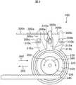
図3は、図1に示した操作入力装置190の各関節175の直動関節に設置する二方向クラッチ180を用いた動力伝達の切断、接続の様子を示す図である。図3において、二方向クラッチ180の動力伝達が遮断されているときの状態が実線で示してあり、二方向クラッチ180のどちらか一方向への動力伝達を接続し、反対方向の回転は動力伝達が切断されていて自由に回転する時の状態を点線で示している。なお、実線の各構成要素に添え字aをつけて示し、点線の各構成要素に添え字bまたはcをつけて示すと共に、各構成要素を総称する場合には添え字a〜cを省略して説明する。 FIG. 3 is a diagram showing a state of disconnection and connection of power transmission using the two-way clutch 180 installed at the linear motion joint of each joint 175 of the
二方向クラッチ180の特徴を簡単に説明する。二方向クラッチ180は、レバー315、ハウジング320、軸受け325を備えている。レバー315がハウジング320に対して実線315aの状態にあるときは、軸受け325の内径側に配置される軸330は自由に回転できるように構成されている。レバー315が図示右側に回転されてレバー315がハウジング320に対して右側点線315aの状態になると、軸受け325の内径側に配置される軸330は、矢印345方向には回転することができず、矢印350側には自由に回転することができる状態となる。レバー315が図示左側に回転されてレバー315がハウジング320に対して左側点線315bの状態になると、軸受け325の内径側に配置される軸330は、矢印350方向には回転することができず、矢印345側には自由に回転することができる状態となる。 The characteristics of the two-way clutch 180 will be briefly described. The two-
ロッド300と一体になっているリンク305は、長穴306を有しており、軸310を介してレバー315と接続されている。軸310はレバー315と一体に設けられている。ハウジング320に対してレバー310が実線のレバー310aの状態にあるときは、軸受け325の内径側に配置される軸330は自由に回転することができるように構成されている。軸330は、軸を同じくしたピニオンギア335と一致して動作する。また、ピニオンギア335はラック340と噛み合っている。ラック340は固定されており、ピニオンギア335はこの固定されたラック340と噛み合わされて拘束されているため、ハウジング320に矢印355あるいは360の方向に力がかかると、レバー315が実線のレバー315aの状態ならば、ハウジング320は矢印355あるいは360の方向に自由に動くことができる。 The
実線のロッド300aにソレノイド185などにより左方から力を加えて点線のロッド300bの状態にすると、ロッド300bと一体のリンク305は点線のリンク305bの状態となる。この際に、軸310はリンク305の長穴306内を動きながら点線の軸310bの状態になり、軸310と一体のレバー315は点線のレバー315bの状態に変化する。この時、二方向クラッチ180の働きにより、軸330および一体化して動くピニオンギア335は矢印345の方向には回転できなくなり、矢印350方向への回転しか動けなくなる。このため、ハウジング320に矢印360方向の力がかかっても矢印360方向にはハウジング320は動けない。一方、矢印355方向には自由に動くことができる。 When a force is applied to the
逆に、ロッド300aをソレノイド185(図1及び図4参照)などにより右方から力を加えて点線のロッド300cの状態にすると、ロッド300cと一体のリンク305は点線のリンク305cの状態となる。軸310はリンク305の長穴306内を動きながら点線の軸310cの状態になり、軸310と一体のレバー315は点線のレバー315cの状態に変化する。この時、二方向クラッチの働きにより、軸330および一体化して動くピニオンギア335は矢印350の方向には回転できなくなり、矢印345方向への回転しか動けなくなる。このため、ハウジング320に矢印355方向の力がかかっても矢印355方向にはハウジング320は動けない。一方、矢印360方向には自由に動くことができる。 On the other hand, when the
図4は図3の二方向クラッチ180を用いた直動関節機構の一軸分の斜視図である。この直動関節機構は、ベース420に対してロッド410が矢印406、407方向に動く直動関節機構であり、次の関節のベース415以降に同様の関節機構が幾つか連結され、把持部200(図2参照)に繋がれている。 FIG. 4 is a perspective view of one axis of the linear motion joint mechanism using the two-
ベース420にはリニアガイドレール425およびラック340が固定されている。リニアガイドレール425上を動くガイド430にはガイドベース440が取り付けられている。ガイドベース440の上には、ロッド固定具435によりロッド410が固定され、クラッチ固定具405によりハウジング320が固定されている。ハウジング320には、二方向クラッチおよび二方向クラッチのレバーを動かす3点ポジショナソレノイド400(図1のソレノイド185に該当)が固定されている。3点ポジショナソレノイド400は、ロッド300を図3で述べたような3状態(ロッド300a、300b、300c)に移動および保持することができるように構成されている。 A
把持部200(図2参照)によって術者170からの入力の力が次の関節のベース415に伝えられると、この関節には矢印406あるいは407方向に沿った力がかかる。3点ポジショナソレノイド400がロッド300を実線のロッド300aの状態で保持していれば、二方向クラッチの動力伝達は切断され、軸330およびピニオンギア335は自由に回転することができる。このようにピニオンギア335はラック340上を自由に回転しながら動くことができるため、次の関節のベース415にかかる力に対応してガイド430は、リニアガイドレール425上を矢印406あるいは407方向に自由に動くことができる。 When the input force from the
一方、把持部200(図2参照)によって術者170からの入力の力が次の関節のベース415に伝えられ、この関節に矢印406方向の力がかかったとする。この時、操作入力装置190を矢印406方向に動かすと、それに対応して動くマニピュレータ110または130の方向に危険領域がありマニピュレータ110または130をその方向に動かしてはいけないということがマスタコントローラ150(図1参照)によって算出されたと仮定する。その場合は、マスタコントローラ150は、3点ポジショナソレノイド400を駆動する信号を発し、レバー315を動かし二方向クラッチの動力伝達機能を接続し、ピニオンギア335を矢印345方向には回転できず矢印350方向に回転できるようにする。このことによりガイド430は、ピニオンギア335とラック340との噛み合いにより、矢印407方向には動けるが、矢印406方向には動くことができなくなる。よって術者170は、安全側な矢印407方向には操作入力できるが、危険領域へ向かう矢印406方向へは操作入力ができなくなり、マニピュレータ110または130を危険領域に動かしてしまうという問題を解決できる。 On the other hand, it is assumed that the input force from the
同様に、次の関節のベース415に矢印407方向の力がかかったとし、この時、操作入力装置190を矢印407方向に動かすと、それに対応して動くマニピュレータ110または130の方向に危険領域がありマニピュレータをその方向に動かしてはいけないということがマスタコントローラ150(図1参照)によって算出されたとする。この場合も、マスタコントローラ150は、3点ポジショナソレノイド400を駆動する信号を発し、レバー315を動かし二方向クラッチの動力伝達機能を接続し、ピニオンギア335を矢印350方向には回転できず矢印345方向に回転できるようにする。このことにより、ガイド430は、ピニオンギア335とラック340との噛み合いにより、矢印406方向には動けるが、矢印407方向には動くことができなくなる。 Similarly, assuming that a force in the direction of the
なお、図示していないが、この関節の移動量はリニアエンコーダによって測定しており、操作入力量をマスタコントローラ150で取得することができる。 Although not shown, the movement amount of the joint is measured by a linear encoder, and the operation input amount can be acquired by the
図5は操作卓240を省いた本実施形態の操作入力装置190の全景を示す図である。 FIG. 5 is a view showing a whole view of the
図2で示した操作卓240の背面にベース585が取り付けられている。ベース585の背面に固定されたリニアガイドレール580上を左右方向である矢印578方向にベース575が動くように、ベース575とリニアガイドレール580とが直動関節を介して繋がっている。ベース585に隠れて見えないが矢印578方向に動くこの直動関節にも本発明の動作方向制限切替機構が取り付けられている。 A
ロッド560は、ベース575に対して、ベース575に取り付けられたラック570と噛み合う動作方向制限切替機構565を介して上下方向である矢印563方向に直動されるように構成されている。ロッド560は固定具555を介してベース550に固定されている。 The
ロッド535は、ベース550に対して、ベース550に固定されたラック545と噛み合う動作方向制限切替機構540を介して前後方向である矢印537方向に直動されるように構成されている。 The
ロッド535に取り付けられた固定具530は軸525を介してリンク520と接続されており、リンク520は軸525を介して回転関節となっている。リンク520は軸515を回転軸としてリンク510と接続しており、リンク510は軸505を介して把持部200と接続されている。 The
図5の操作入力装置190は、直動関節数3、回転関節数3で構成されており、術者は位置姿勢6自由度を入力することができる。なお、把持部200には、図6で説明する術具の開閉関節がある。 The
矢印563、537に対応する直動関節には、操作入力装置の自重を補償するために、図示していない定荷重バネを配置してある。よって術者170は、把持部220を持って操作を行う際、操作入力装置190の自重を気にすることなく自由な操作を可能である。 In the linear motion joints corresponding to the
図5では、回転関節となる軸525、515、505には、動作方向制限切替機構を図示していないが、図3での軸330を関節軸とし、ハウジング220をベースのリンクに固定し、ピニオンギア350の代わりに次の関節のリンクを軸330に固定することにより動作方向制限切替機構が実現できる。 In FIG. 5, the operation direction restriction switching mechanism is not illustrated for the
図5では、直動3関節のみに動作方向制限切替機構を用いることにより、姿勢入力は自由で、位置入力に対してのみ制限をかけることができる。回転3関節にも動作方向制限切替機構をつけることにより、位置姿勢6自由度の制限をかけることができる。 In FIG. 5, by using the movement direction restriction switching mechanism for only the three linear motion joints, the posture input is free and the position input can be restricted only. By attaching an operation direction restriction switching mechanism to the three rotation joints, it is possible to restrict the position and orientation with six degrees of freedom.
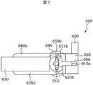
図6及び図7は本実施形態の把持部200の異なる動作状態を示す平面図である。把持部200の移動する構成要素の符号において、図6の状態で添え字aをつけて示し、図7の状態で添え字bをつけて示すと共に、各構成要素を総称する場合には添え字a〜bを省略して説明する。 6 and 7 are plan views showing different operating states of the
この把持部200は、ブレード625、640に人差し指と親指を添え、術具135の開閉操作を入力できる機構となっている。この把持部200の特徴としては、ベース630に対して、ブレード640だけを動かしてもブレード625も対称に動作し、その逆にブレード625を動かしてもブレード640も同様に動く機構となっている。これにより開閉操作を、親指だけで行いたい人、あるいは人差し指だけ行いたい人、あるいは両指で行いたい人へと3種類の方法に対応できる。 The
ベース630と一体のカム押え605には、カムプレート610が直動できる穴606が形成されている。軸615は、ブレード625、640の回転中心軸であり、ベース630を通して動作方向制限切替機構645の軸となっている。軸615はブレード625と一体で回転するようにしておくことにより、動作方向制限切替機構645によりブレード開閉の角度の制限をかけることができる。動作方向制限切替機構645は3点ポジショナソレノイド600を含む。また、図示していないエンコーダによってブレード開閉の角度も取得できるように構成されている。 A
また、軸615はカムプレート610のカム穴651を通っている。カムプレート610のカム穴651には、ブレード640と一体になっている軸650、ブレード625と一体になっている軸620がそれぞれ通っている。 The
図6のブレード640aが図7のブレード640bのように閉じられる方向に力がかかると、ブレード640aは軸615を中心に回転し、ブレード640aと一体として動く軸650aも軸615を回転中心として動く。軸650aはカム穴651aを通して図6のカムプレート610aを図7のカムプレート610bのように動かす。カムプレート610aがカムプレート610bのように動くことにより、カム穴651aを通して軸620aに軸620bとなる方向に力が加わり、軸620aと一体のブレード625aはブレード625bとなる。 When a force is applied in the direction in which the
本実施形態では、2枚のブレードを同時に開閉する機構のために、従来の一般的な平行リンクを用いた機構などと比較して、単純で安価に製作が可能である。 In the present embodiment, the mechanism that opens and closes two blades at the same time is simpler and cheaper to manufacture than a conventional mechanism using a parallel link.
また、動作方向制限切替機構645を用いることにより、把持開閉の大きさを制限したり、閉じたままの状態を維持したりすることなどが可能となる。術具ブレード640、625を使って患部を押し開く動作において、術具135を開く量を制限したい時などには、術具ブレード640、625の開閉の大きさを制限することができるので、安全性の向上につながる。また、閉じた状態を維持することができるので、術者170は針など対象物を握っている状態で力をこめて握っている必要がなくなり、これによって疲労度が少なくなる。なお、ブレード640、625は、図示していないバネにより、通常、図6のように開いた状態になっている。 Further, by using the operation direction
開閉ベース630にはマイクロスイッチ635が配置されており、マイクロスイッチ635はブレード640aを640bの状態にして強く押されることにより反応する。本実施形態では、マイクロスイッチ635が反応した時、動作方向制限切替機構645が働き、ブレード640、625が閉じられた状態で保持される仕組みとなっている。なお、ブレード640、625が閉じられた状態を解除するためには、図示していな別のボタンを指で押すことにより実現するようになっている。 A
術具開閉量を制限する時には、予め入力インターフェース116により最大開閉量を入力しておき、動作方向制限切替機構645を用いる。 When restricting the opening / closing amount of the surgical instrument, the maximum opening / closing amount is input in advance by the input interface 116, and the operation direction
また、動作方向制限切替機構645において、動力伝達の接続方向と遮断をマスタコントローラ150によって制御することにより、障害物や危険領域の壁を表現するだけでなく、マニピュレータアームが対象物に接触した際の柔軟さや固さを力覚提示することができる。すなわち、コントローラ150は、動力伝達の切断と動力伝達接続方向を選択して接続を細かく切替えることにより、マニピュレータ110または130のアームが対象物に接触した際の力覚を提示するように構成されている。 Further, in the operation direction
以上、説明したように、本実施形態によれば、安全領域や危険領域などの提示を必要としない時には、自由に操作入力装置190を動かすことができ、安全領域や危険領域などの提示を必要とする時には、モータを用いずに、危険領域方向への動きを制限し、安全領域方向への動きは自由な動作を実現することができる。しかも、操作入力装置190にモータを用いずに、術者に制限された動作範囲や障害物を力覚的に提示することが可能となり、小型化および制御安定性の面で非常に効果的であり、操作性のよい操作入力装置190とすることができる。また、モータを有しないため、MRI環境下などのノイズの影響を低減したい環境では、非常に効果的である。さらに、モータを有しないため安価に製作可能である。 As described above, according to the present embodiment, when it is not necessary to present a safe area or a dangerous area, the
また、術具135の開閉操作においても、例えば、術具135によって押し開く動作において術具135の開く量を制限したり、術具135を閉じた際に把持部200を押しつづける疲労を軽減したりするといったことを実現でき、操作性を向上させることができる。 Further, in the opening / closing operation of the
なお、本実施形態では、動作方向制限切替機構を実現する動力伝達の遮断・接続機構として二方向クラッチを用いたが、一方向クラッチおよびソレノイドを二つずつ用いて実現してもよい。 In the present embodiment, the two-way clutch is used as the power transmission cutoff / connection mechanism for realizing the operation direction restriction switching mechanism. However, the two-way clutch and the solenoid may be used in two.
本実施形態では、手術支援マニピュレータの操作入力装置について述べたが、本発明は、ヒューマノイドのアームや産業用マニピュレータのアームなどの操作入力装置として実施することもできる。 In the present embodiment, the operation input device of the surgery support manipulator has been described, but the present invention can also be implemented as an operation input device such as a humanoid arm or an industrial manipulator arm.
100…参照モニタ、105…コンバータ、110…第1のマニピュレータ、115…位置情報統合コントローラ、116…入力インターフェース(位置姿勢入力装置)、120…診断装置、125…内視鏡、130…第2のマニピュレータ、135…術具、140…患者、145…スレーブコントローラ、150…マスタコントローラ、155…センサ、165…入力インターフェース(把持部200)、170…術者(操作者)、175…関節、180…二方向クラッチ、185…ソレノイド、190…操作入力装置、200…把持部(入力インターフェース165)、205、210、225、220、215…リンク、240…操作卓、300…ロッド、305…リンク、306…長穴、310…軸、315…レバー、320…ハウジング、325…軸受け、330…軸、335…ピニオンギア、400…3点ポジショナソレノイド、405…クラッチ固定具、410…ロッド、415…関節のベース、420…ベース、425…リニアガイドレール、430…ガイド、440…ガイドベース、435…ロッド固定具、505…軸、510…リンク、515…軸、520…リンク、525…軸、530…固定具、535…ロッド、540…動作方向制限切替機構、545…ラック、550…ベース、555…固定具、560…ロッド、565…動作方向制限切替機構、570…ラック、575…ベース、580…リニアガイドレール、585…ベース、625…ブレード、630…ベース、640…ブレード。 DESCRIPTION OF
Claims (10)
Translated fromJapanese前記マニピュレータのアームを動かす操作入力装置と、
前記マニピュレータ及び前記操作入力装置を制御するコントローラとを備えたマスタ・スレーブ式マニピュレータシステムにおいて、
前記操作入力装置はその関節に動力伝達の切断と動力伝達を接続してその動力伝達接続方向を選択可能な動作方向制限切替機構を備えた
ことを特徴とするマスタ・スレーブ式マニピュレータシステム。A manipulator having an arm;
An operation input device for moving the arm of the manipulator;
In a master / slave manipulator system comprising the manipulator and a controller for controlling the operation input device,
The master / slave manipulator system, wherein the operation input device comprises an operation direction restriction switching mechanism capable of selecting a power transmission connection direction by connecting a power transmission cut and a power transmission to the joint.
その関節に動力伝達の切断と動力伝達を接続してその動力伝達接続方向を選択可能な動作方向制限切替機構を備えた
ことを特徴とする操作入力装置。In the operation input device that moves the arm of the manipulator in the master / slave manipulator system,
An operation input device comprising an operation direction restriction switching mechanism capable of selecting power transmission connection direction by connecting power transmission cutting and power transmission to the joint.
Priority Applications (4)
| Application Number | Priority Date | Filing Date | Title |
|---|---|---|---|
| JP2005147786AJP2006321027A (en) | 2005-05-20 | 2005-05-20 | Master / slave manipulator system and its operation input device |
| US11/434,900US7391177B2 (en) | 2005-05-20 | 2006-05-17 | Master-slave manipulator system and this operation input devices |
| EP06010411AEP1724071A1 (en) | 2005-05-20 | 2006-05-19 | Master-slave manipulator system and its operation input device |
| CNB2006100824562ACN100522504C (en) | 2005-05-20 | 2006-05-19 | Master-slave manipulator system and its operation input device |
Applications Claiming Priority (1)
| Application Number | Priority Date | Filing Date | Title |
|---|---|---|---|
| JP2005147786AJP2006321027A (en) | 2005-05-20 | 2005-05-20 | Master / slave manipulator system and its operation input device |
Publications (2)
| Publication Number | Publication Date |
|---|---|
| JP2006321027Atrue JP2006321027A (en) | 2006-11-30 |
| JP2006321027A5 JP2006321027A5 (en) | 2008-07-03 |
Family
ID=36758241
Family Applications (1)
| Application Number | Title | Priority Date | Filing Date |
|---|---|---|---|
| JP2005147786APendingJP2006321027A (en) | 2005-05-20 | 2005-05-20 | Master / slave manipulator system and its operation input device |
Country Status (4)
| Country | Link |
|---|---|
| US (1) | US7391177B2 (en) |
| EP (1) | EP1724071A1 (en) |
| JP (1) | JP2006321027A (en) |
| CN (1) | CN100522504C (en) |
Cited By (32)
| Publication number | Priority date | Publication date | Assignee | Title |
|---|---|---|---|---|
| JP2008173724A (en)* | 2007-01-19 | 2008-07-31 | Hitachi Ltd | Master / slave manipulator system |
| WO2009069327A1 (en)* | 2007-11-30 | 2009-06-04 | The University Of Tokyo | Master manipulator used in surgery support system |
| JP2012055752A (en)* | 2005-10-20 | 2012-03-22 | Intuitive Surgical Inc | Auxiliary image display and manipulation on computer display in medical robotic system |
| WO2013018935A1 (en)* | 2011-08-04 | 2013-02-07 | Olympus Corporation | Surgical instrument and control method thereof |
| WO2013018861A1 (en)* | 2011-08-04 | 2013-02-07 | オリンパス株式会社 | Medical manipulator and method for controlling same |
| JPWO2013018861A1 (en)* | 2011-08-04 | 2015-03-05 | オリンパス株式会社 | Medical manipulator and control method thereof |
| JP2015116660A (en)* | 2013-11-13 | 2015-06-25 | パナソニックIpマネジメント株式会社 | Master device for master-slave device, control method therefor, and master-slave device |
| US9161772B2 (en) | 2011-08-04 | 2015-10-20 | Olympus Corporation | Surgical instrument and medical manipulator |
| US9218053B2 (en) | 2011-08-04 | 2015-12-22 | Olympus Corporation | Surgical assistant system |
| US9244523B2 (en) | 2011-08-04 | 2016-01-26 | Olympus Corporation | Manipulator system |
| US9423869B2 (en) | 2011-08-04 | 2016-08-23 | Olympus Corporation | Operation support device |
| US9477301B2 (en) | 2011-08-04 | 2016-10-25 | Olympus Corporation | Operation support device and assembly method thereof |
| US9519341B2 (en) | 2011-08-04 | 2016-12-13 | Olympus Corporation | Medical manipulator and surgical support apparatus |
| US9524022B2 (en) | 2011-08-04 | 2016-12-20 | Olympus Corporation | Medical equipment |
| US9568992B2 (en) | 2011-08-04 | 2017-02-14 | Olympus Corporation | Medical manipulator |
| US9632577B2 (en) | 2011-08-04 | 2017-04-25 | Olympus Corporation | Operation support device and control method thereof |
| US9671860B2 (en) | 2011-08-04 | 2017-06-06 | Olympus Corporation | Manipulation input device and manipulator system having the same |
| JP2017515524A (en)* | 2014-03-17 | 2017-06-15 | インテュイティブ サージカル オペレーションズ, インコーポレイテッド | Structure adjustment system and method for teleoperated medical system |
| WO2017169096A1 (en)* | 2016-03-29 | 2017-10-05 | ソニー株式会社 | Medical support arm control device, medical support arm device control method, and medical system |
| US9851782B2 (en) | 2011-08-04 | 2017-12-26 | Olympus Corporation | Operation support device and attachment and detachment method thereof |
| WO2018216382A1 (en)* | 2017-05-26 | 2018-11-29 | ソニー株式会社 | Medical system, control device for medical support arm, and control method for medical support arm |
| JP2019500914A (en)* | 2015-10-22 | 2019-01-17 | コヴィディエン リミテッド パートナーシップ | Variable scanning for input devices |
| WO2019099504A1 (en)* | 2017-11-15 | 2019-05-23 | Intuitive Surgical Operations, Inc. | Master control device with multi-finger grip and methods therefor |
| WO2019099584A1 (en)* | 2017-11-15 | 2019-05-23 | Intuitive Surgical Operations, Inc. | Master control device and methods therefor |
| JP2020049300A (en)* | 2019-12-25 | 2020-04-02 | 株式会社メディカロイド | Remote control device and remote operation system |
| KR102261262B1 (en)* | 2020-04-22 | 2021-06-07 | 주식회사 이지엔도서지컬 | Master device for controlling an slave device |
| US11351001B2 (en) | 2015-08-17 | 2022-06-07 | Intuitive Surgical Operations, Inc. | Ungrounded master control devices and methods of use |
| WO2023112732A1 (en)* | 2021-12-13 | 2023-06-22 | ソニーグループ株式会社 | Robot system and coordinate registration method |
| JPWO2025017922A1 (en)* | 2023-07-20 | 2025-01-23 | ||
| JPWO2025017923A1 (en)* | 2023-07-20 | 2025-01-23 | ||
| US12242662B2 (en) | 2019-10-08 | 2025-03-04 | Intuitive Surgical Operations, Inc. | Hand presence sensing at control input device |
| US12329487B2 (en) | 2018-05-11 | 2025-06-17 | Intuitive Surgical Operations, Inc. | Master control device with finger grip sensing and methods therefor |
Families Citing this family (74)
| Publication number | Priority date | Publication date | Assignee | Title |
|---|---|---|---|---|
| US8944070B2 (en) | 1999-04-07 | 2015-02-03 | Intuitive Surgical Operations, Inc. | Non-force reflecting method for providing tool force information to a user of a telesurgical system |
| US9789608B2 (en) | 2006-06-29 | 2017-10-17 | Intuitive Surgical Operations, Inc. | Synthetic representation of a surgical robot |
| KR101477133B1 (en)* | 2006-06-13 | 2014-12-29 | 인튜어티브 서지컬 인코포레이티드 | Minimally invasive surgical system |
| US12357400B2 (en) | 2006-06-29 | 2025-07-15 | Intuitive Surgical Operations, Inc. | Synthetic representation of a surgical robot |
| US9718190B2 (en)* | 2006-06-29 | 2017-08-01 | Intuitive Surgical Operations, Inc. | Tool position and identification indicator displayed in a boundary area of a computer display screen |
| US10258425B2 (en) | 2008-06-27 | 2019-04-16 | Intuitive Surgical Operations, Inc. | Medical robotic system providing an auxiliary view of articulatable instruments extending out of a distal end of an entry guide |
| US10008017B2 (en) | 2006-06-29 | 2018-06-26 | Intuitive Surgical Operations, Inc. | Rendering tool information as graphic overlays on displayed images of tools |
| US20090192523A1 (en) | 2006-06-29 | 2009-07-30 | Intuitive Surgical, Inc. | Synthetic representation of a surgical instrument |
| JP4891823B2 (en)* | 2007-03-29 | 2012-03-07 | オリンパスメディカルシステムズ株式会社 | Endoscope device |
| US8620473B2 (en) | 2007-06-13 | 2013-12-31 | Intuitive Surgical Operations, Inc. | Medical robotic system with coupled control modes |
| US8903546B2 (en) | 2009-08-15 | 2014-12-02 | Intuitive Surgical Operations, Inc. | Smooth control of an articulated instrument across areas with different work space conditions |
| US9138129B2 (en) | 2007-06-13 | 2015-09-22 | Intuitive Surgical Operations, Inc. | Method and system for moving a plurality of articulated instruments in tandem back towards an entry guide |
| US9469034B2 (en) | 2007-06-13 | 2016-10-18 | Intuitive Surgical Operations, Inc. | Method and system for switching modes of a robotic system |
| US9089256B2 (en) | 2008-06-27 | 2015-07-28 | Intuitive Surgical Operations, Inc. | Medical robotic system providing an auxiliary view including range of motion limitations for articulatable instruments extending out of a distal end of an entry guide |
| US9084623B2 (en) | 2009-08-15 | 2015-07-21 | Intuitive Surgical Operations, Inc. | Controller assisted reconfiguration of an articulated instrument during movement into and out of an entry guide |
| JP5209903B2 (en)* | 2007-06-18 | 2013-06-12 | オリンパスメディカルシステムズ株式会社 | Power transmission device for electric bending endoscope |
| US8864652B2 (en)* | 2008-06-27 | 2014-10-21 | Intuitive Surgical Operations, Inc. | Medical robotic system providing computer generated auxiliary views of a camera instrument for controlling the positioning and orienting of its tip |
| US12239396B2 (en) | 2008-06-27 | 2025-03-04 | Intuitive Surgical Operations, Inc. | Medical robotic system providing an auxiliary view including range of motion limitations for articulatable instruments extending out of a distal end of an entry guide |
| US8332072B1 (en) | 2008-08-22 | 2012-12-11 | Titan Medical Inc. | Robotic hand controller |
| US12266040B2 (en) | 2009-03-31 | 2025-04-01 | Intuitive Surgical Operations, Inc. | Rendering tool information as graphic overlays on displayed images of tools |
| US8918211B2 (en) | 2010-02-12 | 2014-12-23 | Intuitive Surgical Operations, Inc. | Medical robotic system providing sensory feedback indicating a difference between a commanded state and a preferred pose of an articulated instrument |
| US9492927B2 (en) | 2009-08-15 | 2016-11-15 | Intuitive Surgical Operations, Inc. | Application of force feedback on an input device to urge its operator to command an articulated instrument to a preferred pose |
| WO2012073789A1 (en) | 2010-11-30 | 2012-06-07 | オリンパス株式会社 | Master control input device and master-slave manipulator |
| US9119655B2 (en) | 2012-08-03 | 2015-09-01 | Stryker Corporation | Surgical manipulator capable of controlling a surgical instrument in multiple modes |
| JP5669590B2 (en)* | 2011-01-20 | 2015-02-12 | オリンパス株式会社 | Master-slave manipulator and medical master-slave manipulator |
| JP2012171088A (en)* | 2011-02-24 | 2012-09-10 | Olympus Corp | Master operation input device, and master-slave manipulator |
| KR102109615B1 (en)* | 2011-05-31 | 2020-05-12 | 인튜어티브 서지컬 오퍼레이션즈 인코포레이티드 | Positive control of robotic surgical instrument end effector |
| WO2013009887A1 (en)* | 2011-07-11 | 2013-01-17 | Board Of Regents Of The University Of Nebraska | Robotic surgical devices, systems and related methods |
| WO2013052137A2 (en) | 2011-10-03 | 2013-04-11 | Board Of Regents Of The University Of Nebraska | Robotic surgical devices, systems and related methods |
| WO2013122889A1 (en)* | 2012-02-15 | 2013-08-22 | Intuitive Surgical Operations, Inc. | Switching control of an instrument to an input device upon the instrument entering a display area viewable by an operator of the input device |
| EP2844181B1 (en) | 2012-05-01 | 2021-03-10 | Board of Regents of the University of Nebraska | Single site robotic device and related systems |
| CN107198567B (en) | 2012-08-03 | 2021-02-09 | 史赛克公司 | Systems and methods for robotic surgery |
| US9226796B2 (en) | 2012-08-03 | 2016-01-05 | Stryker Corporation | Method for detecting a disturbance as an energy applicator of a surgical instrument traverses a cutting path |
| EP2882331A4 (en) | 2012-08-08 | 2016-03-23 | Univ Nebraska | ROBOTIC SURGICAL SYSTEMS AND DEVICES, AND ASSOCIATED METHODS |
| US12295680B2 (en) | 2012-08-08 | 2025-05-13 | Board Of Regents Of The University Of Nebraska | Robotic surgical devices, systems and related methods |
| CN103085055B (en)* | 2013-01-29 | 2016-06-22 | 山东电力集团公司电力科学研究院 | Position Feedback Master Hand System of Live Repair Robot |
| US10507066B2 (en) | 2013-02-15 | 2019-12-17 | Intuitive Surgical Operations, Inc. | Providing information of tools by filtering image areas adjacent to or on displayed images of the tools |
| CA2906672C (en) | 2013-03-14 | 2022-03-15 | Board Of Regents Of The University Of Nebraska | Methods, systems, and devices relating to force control surgical systems |
| CN105188511B (en)* | 2013-03-29 | 2017-08-15 | 奥林巴斯株式会社 | Master-slave system and its driving method |
| US10966700B2 (en) | 2013-07-17 | 2021-04-06 | Virtual Incision Corporation | Robotic surgical devices, systems and related methods |
| JP6164964B2 (en)* | 2013-07-26 | 2017-07-19 | オリンパス株式会社 | Medical system and control method thereof |
| CN106163445B (en) | 2014-03-31 | 2019-11-29 | 直观外科手术操作公司 | Surgical instruments with switchable drives |
| CN106163444B (en) | 2014-04-01 | 2019-06-28 | 直观外科手术操作公司 | Control Input Accuracy of Teleoperated Surgical Instruments |
| US10660717B2 (en) | 2014-04-24 | 2020-05-26 | Covidien Lp | Robotic interface positioning determination systems and methods |
| US10112296B2 (en)* | 2014-08-08 | 2018-10-30 | Bbz S.R.L. | Remote manipulation input device |
| EP3217890B1 (en) | 2014-11-11 | 2020-04-08 | Board of Regents of the University of Nebraska | Robotic device with compact joint design |
| US9592608B1 (en) | 2014-12-15 | 2017-03-14 | X Development Llc | Methods and systems for providing feedback during teach mode |
| CA2977582A1 (en) | 2015-03-26 | 2016-09-29 | Covidien Lp | Input device assemblies for robotic surgical systems |
| CN107847284B (en) | 2015-06-16 | 2021-03-23 | 提坦医疗公司 | Handle apparatus for receiving operator input in a robotic surgical system |
| JP6520478B2 (en)* | 2015-06-30 | 2019-05-29 | 株式会社デンソーウェーブ | Robot arm operation system |
| WO2017024081A1 (en) | 2015-08-03 | 2017-02-09 | Board Of Regents Of The University Of Nebraska | Robotic surgical devices systems and related methods |
| JP6660157B2 (en)* | 2015-11-16 | 2020-03-11 | 川崎重工業株式会社 | Robot and work method by robot |
| US9919422B1 (en)* | 2016-01-06 | 2018-03-20 | X Development Llc | Methods and systems to provide mechanical feedback during movement of a robotic system |
| US10717194B2 (en) | 2016-02-26 | 2020-07-21 | Intuitive Surgical Operations, Inc. | System and method for collision avoidance using virtual boundaries |
| CA3024623A1 (en) | 2016-05-18 | 2017-11-23 | Virtual Incision Corporation | Robotic surgical devices, systems and related methods |
| CN109195543A (en)* | 2016-06-03 | 2019-01-11 | 柯惠Lp公司 | Passive Shaft Systems for Robotic Surgical Systems |
| CN107708594B (en) | 2016-06-03 | 2021-03-05 | 柯惠Lp公司 | Control arm assembly for robotic surgical system |
| CN107735040B (en)* | 2016-06-03 | 2021-06-18 | 柯惠Lp公司 | Control Arms for Robotic Surgical Systems |
| WO2018045036A1 (en) | 2016-08-30 | 2018-03-08 | Board Of Regents Of The University Of Nebraska | Robotic device with compact joint design and an additional degree of freedom and related systems and methods |
| US11202682B2 (en) | 2016-12-16 | 2021-12-21 | Mako Surgical Corp. | Techniques for modifying tool operation in a surgical robotic system based on comparing actual and commanded states of the tool relative to a surgical site |
| CN117017492A (en) | 2017-09-27 | 2023-11-10 | 虚拟切割有限公司 | Robotic surgical device with tracking camera technology and related systems and methods |
| JP6936712B2 (en)* | 2017-11-24 | 2021-09-22 | 川崎重工業株式会社 | Operating device |
| CA3087672A1 (en) | 2018-01-05 | 2019-07-11 | Board Of Regents Of The University Of Nebraska | Single-arm robotic device with compact joint design and related systems and methods |
| US10758311B2 (en)* | 2018-10-30 | 2020-09-01 | Titan Medical Inc. | Hand controller apparatus for gesture control and shared input control in a robotic surgery system |
| US10426561B1 (en) | 2018-10-30 | 2019-10-01 | Titan Medical Inc. | Hand controller apparatus for detecting input position in a robotic surgery system |
| US11166769B2 (en) | 2018-10-30 | 2021-11-09 | Titan Medical Inc. | Hand controller apparatus with feedback responsive to function change in a robotic surgery system |
| US11116591B2 (en) | 2018-10-30 | 2021-09-14 | Titan Medical Inc. | Hand controller apparatus including ergonomic features for a robotic surgery system |
| WO2020146348A1 (en) | 2019-01-07 | 2020-07-16 | Virtual Incision Corporation | Robotically assisted surgical system and related devices and methods |
| US11504200B2 (en) | 2019-01-24 | 2022-11-22 | Verb Surgical Inc. | Wearable user interface device |
| CN111730598B (en)* | 2020-07-06 | 2022-01-04 | 武汉联影智融医疗科技有限公司 | Robot force position interlocking control method, device and system |
| CN112716608B (en)* | 2021-01-20 | 2022-06-24 | 山东威高手术机器人有限公司 | Master-slave tracking control method for minimally invasive surgery robot |
| US12082896B2 (en)* | 2021-08-04 | 2024-09-10 | Pixee Medical | Surgical navigation system on wearable computer combining augmented reality and robotics |
| CN114789432B (en)* | 2022-03-31 | 2023-08-29 | 西安交通大学 | Double-arm robot manpower-position hybrid control method for building board installation |
| CN114770458B (en)* | 2022-04-28 | 2023-09-15 | 燕山大学 | Master-slave bidirectional control method and system for redundancy degree-of-freedom teleoperation robot |
Citations (4)
| Publication number | Priority date | Publication date | Assignee | Title |
|---|---|---|---|---|
| JP2002017752A (en)* | 2000-07-11 | 2002-01-22 | Olympus Optical Co Ltd | Endoscopic surgery system |
| JP2003299674A (en)* | 2002-04-12 | 2003-10-21 | Masasuke Shiraishi | Operation table device |
| JP2004223128A (en)* | 2003-01-27 | 2004-08-12 | Hitachi Ltd | Medical practice support apparatus and method |
| JP2005030451A (en)* | 2003-07-08 | 2005-02-03 | Alps Electric Co Ltd | Kinesthetic sense application type input device |
Family Cites Families (9)
| Publication number | Priority date | Publication date | Assignee | Title |
|---|---|---|---|---|
| US5672044A (en)* | 1974-01-24 | 1997-09-30 | Lemelson; Jerome H. | Free-traveling manipulator with powered tools |
| FR2691093B1 (en) | 1992-05-12 | 1996-06-14 | Univ Joseph Fourier | ROBOT FOR GUIDANCE OF GESTURES AND CONTROL METHOD. |
| US6437771B1 (en) | 1995-01-18 | 2002-08-20 | Immersion Corporation | Force feedback device including flexure member between actuator and user object |
| JP2567198B2 (en) | 1993-10-29 | 1996-12-25 | 株式会社明電舎 | Master-slave type manipulator |
| US5792135A (en)* | 1996-05-20 | 1998-08-11 | Intuitive Surgical, Inc. | Articulated surgical instrument for performing minimally invasive surgery with enhanced dexterity and sensitivity |
| US6233504B1 (en)* | 1998-04-16 | 2001-05-15 | California Institute Of Technology | Tool actuation and force feedback on robot-assisted microsurgery system |
| JP3178813B2 (en) | 1998-05-29 | 2001-06-25 | 川崎重工業株式会社 | Remote control device |
| US7831292B2 (en)* | 2002-03-06 | 2010-11-09 | Mako Surgical Corp. | Guidance system and method for surgical procedures with improved feedback |
| JP3912251B2 (en) | 2002-10-02 | 2007-05-09 | 株式会社日立製作所 | manipulator |
- 2005
- 2005-05-20JPJP2005147786Apatent/JP2006321027A/enactivePending
- 2006
- 2006-05-17USUS11/434,900patent/US7391177B2/enactiveActive
- 2006-05-19EPEP06010411Apatent/EP1724071A1/ennot_activeWithdrawn
- 2006-05-19CNCNB2006100824562Apatent/CN100522504C/ennot_activeExpired - Fee Related
Patent Citations (4)
| Publication number | Priority date | Publication date | Assignee | Title |
|---|---|---|---|---|
| JP2002017752A (en)* | 2000-07-11 | 2002-01-22 | Olympus Optical Co Ltd | Endoscopic surgery system |
| JP2003299674A (en)* | 2002-04-12 | 2003-10-21 | Masasuke Shiraishi | Operation table device |
| JP2004223128A (en)* | 2003-01-27 | 2004-08-12 | Hitachi Ltd | Medical practice support apparatus and method |
| JP2005030451A (en)* | 2003-07-08 | 2005-02-03 | Alps Electric Co Ltd | Kinesthetic sense application type input device |
Cited By (43)
| Publication number | Priority date | Publication date | Assignee | Title |
|---|---|---|---|---|
| JP2012055752A (en)* | 2005-10-20 | 2012-03-22 | Intuitive Surgical Inc | Auxiliary image display and manipulation on computer display in medical robotic system |
| JP2008173724A (en)* | 2007-01-19 | 2008-07-31 | Hitachi Ltd | Master / slave manipulator system |
| US8009140B2 (en) | 2007-01-19 | 2011-08-30 | Hitachi, Ltd. | Master-slave manipulator system |
| WO2009069327A1 (en)* | 2007-11-30 | 2009-06-04 | The University Of Tokyo | Master manipulator used in surgery support system |
| JP2009131446A (en)* | 2007-11-30 | 2009-06-18 | Univ Of Tokyo | Master manipulator used in surgery support system |
| US9632577B2 (en) | 2011-08-04 | 2017-04-25 | Olympus Corporation | Operation support device and control method thereof |
| US9851782B2 (en) | 2011-08-04 | 2017-12-26 | Olympus Corporation | Operation support device and attachment and detachment method thereof |
| JP2013034832A (en)* | 2011-08-04 | 2013-02-21 | Olympus Corp | Surgical instrument and control method thereof |
| JPWO2013018861A1 (en)* | 2011-08-04 | 2015-03-05 | オリンパス株式会社 | Medical manipulator and control method thereof |
| WO2013018861A1 (en)* | 2011-08-04 | 2013-02-07 | オリンパス株式会社 | Medical manipulator and method for controlling same |
| US9161772B2 (en) | 2011-08-04 | 2015-10-20 | Olympus Corporation | Surgical instrument and medical manipulator |
| US9218053B2 (en) | 2011-08-04 | 2015-12-22 | Olympus Corporation | Surgical assistant system |
| US9244523B2 (en) | 2011-08-04 | 2016-01-26 | Olympus Corporation | Manipulator system |
| US9244524B2 (en) | 2011-08-04 | 2016-01-26 | Olympus Corporation | Surgical instrument and control method thereof |
| US9423869B2 (en) | 2011-08-04 | 2016-08-23 | Olympus Corporation | Operation support device |
| US9477301B2 (en) | 2011-08-04 | 2016-10-25 | Olympus Corporation | Operation support device and assembly method thereof |
| US9519341B2 (en) | 2011-08-04 | 2016-12-13 | Olympus Corporation | Medical manipulator and surgical support apparatus |
| US9524022B2 (en) | 2011-08-04 | 2016-12-20 | Olympus Corporation | Medical equipment |
| US9568992B2 (en) | 2011-08-04 | 2017-02-14 | Olympus Corporation | Medical manipulator |
| US9632573B2 (en) | 2011-08-04 | 2017-04-25 | Olympus Corporation | Medical manipulator and method of controlling the same |
| WO2013018935A1 (en)* | 2011-08-04 | 2013-02-07 | Olympus Corporation | Surgical instrument and control method thereof |
| US9671860B2 (en) | 2011-08-04 | 2017-06-06 | Olympus Corporation | Manipulation input device and manipulator system having the same |
| JP2015116660A (en)* | 2013-11-13 | 2015-06-25 | パナソニックIpマネジメント株式会社 | Master device for master-slave device, control method therefor, and master-slave device |
| JP2017515524A (en)* | 2014-03-17 | 2017-06-15 | インテュイティブ サージカル オペレーションズ, インコーポレイテッド | Structure adjustment system and method for teleoperated medical system |
| US11351001B2 (en) | 2015-08-17 | 2022-06-07 | Intuitive Surgical Operations, Inc. | Ungrounded master control devices and methods of use |
| US12023122B2 (en) | 2015-08-17 | 2024-07-02 | Intuitive Surgical Operations, Inc. | Ungrounded master control devices and methods of use |
| JP2019500914A (en)* | 2015-10-22 | 2019-01-17 | コヴィディエン リミテッド パートナーシップ | Variable scanning for input devices |
| WO2017169096A1 (en)* | 2016-03-29 | 2017-10-05 | ソニー株式会社 | Medical support arm control device, medical support arm device control method, and medical system |
| WO2018216382A1 (en)* | 2017-05-26 | 2018-11-29 | ソニー株式会社 | Medical system, control device for medical support arm, and control method for medical support arm |
| US11633240B2 (en) | 2017-05-26 | 2023-04-25 | Sony Corporation | Medical system, control device of medical support arm, and control method of medical support arm |
| WO2019099504A1 (en)* | 2017-11-15 | 2019-05-23 | Intuitive Surgical Operations, Inc. | Master control device with multi-finger grip and methods therefor |
| US11712314B2 (en) | 2017-11-15 | 2023-08-01 | Intuitive Surgical Operations, Inc. | Master control device and methods therefor |
| WO2019099584A1 (en)* | 2017-11-15 | 2019-05-23 | Intuitive Surgical Operations, Inc. | Master control device and methods therefor |
| US12048505B2 (en) | 2017-11-15 | 2024-07-30 | Intuitive Surgical Operations, Inc. | Master control device and methods therefor |
| US12419715B2 (en) | 2017-11-15 | 2025-09-23 | Intuitive Surgical Operations, Inc. | Master control device with multi-finger grip and methods therefor |
| US12329487B2 (en) | 2018-05-11 | 2025-06-17 | Intuitive Surgical Operations, Inc. | Master control device with finger grip sensing and methods therefor |
| US12242662B2 (en) | 2019-10-08 | 2025-03-04 | Intuitive Surgical Operations, Inc. | Hand presence sensing at control input device |
| JP2020049300A (en)* | 2019-12-25 | 2020-04-02 | 株式会社メディカロイド | Remote control device and remote operation system |
| WO2021215605A1 (en)* | 2020-04-22 | 2021-10-28 | 주식회사 이지엔도서지컬 | Master device for controlling slave device |
| KR102261262B1 (en)* | 2020-04-22 | 2021-06-07 | 주식회사 이지엔도서지컬 | Master device for controlling an slave device |
| WO2023112732A1 (en)* | 2021-12-13 | 2023-06-22 | ソニーグループ株式会社 | Robot system and coordinate registration method |
| JPWO2025017922A1 (en)* | 2023-07-20 | 2025-01-23 | ||
| JPWO2025017923A1 (en)* | 2023-07-20 | 2025-01-23 |
Also Published As
| Publication number | Publication date |
|---|---|
| EP1724071A1 (en) | 2006-11-22 |
| CN1864938A (en) | 2006-11-22 |
| US20060261770A1 (en) | 2006-11-23 |
| CN100522504C (en) | 2009-08-05 |
| US7391177B2 (en) | 2008-06-24 |
Similar Documents
| Publication | Publication Date | Title |
|---|---|---|
| JP2006321027A (en) | Master / slave manipulator system and its operation input device | |
| US12213755B2 (en) | Actuated grips for controller | |
| CN110604618B (en) | User interface device with clamping link | |
| JP6954836B2 (en) | Robot system for surgery | |
| US6233504B1 (en) | Tool actuation and force feedback on robot-assisted microsurgery system | |
| US10503199B1 (en) | Pedal with sliding and locking mechanisms for surgical robots | |
| CN113924059B (en) | Sensors for touchless control of surgical robotic systems | |
| JP7427815B2 (en) | User interface device with grip links | |
| US12415284B2 (en) | Moveable display system | |
| US20220296323A1 (en) | Moveable display unit on track | |
| JP2023030101A (en) | Console for controlling the robot manipulator | |
| KR20200075535A (en) | User interface device, master console for surgical robot apparatus and operating method of master console | |
| CN111818872A (en) | camera control | |
| JP2006150105A (en) | Medical manipulator | |
| US12440298B2 (en) | User interface device having grip linkages | |
| WO2025207554A1 (en) | Inter-instrument collision avoidance for computer-assisted systems |
Legal Events
| Date | Code | Title | Description |
|---|---|---|---|
| A521 | Request for written amendment filed | Free format text:JAPANESE INTERMEDIATE CODE: A523 Effective date:20080515 | |
| A621 | Written request for application examination | Free format text:JAPANESE INTERMEDIATE CODE: A621 Effective date:20080515 | |
| RD02 | Notification of acceptance of power of attorney | Free format text:JAPANESE INTERMEDIATE CODE: A7422 Effective date:20080515 | |
| A977 | Report on retrieval | Free format text:JAPANESE INTERMEDIATE CODE: A971007 Effective date:20100310 | |
| A131 | Notification of reasons for refusal | Free format text:JAPANESE INTERMEDIATE CODE: A131 Effective date:20100316 | |
| A02 | Decision of refusal | Free format text:JAPANESE INTERMEDIATE CODE: A02 Effective date:20100706 |