Movatterモバイル変換


[0]ホーム

URL:


JP2006308543A - Angular velocity sensor - Google Patents

Angular velocity sensor
Download PDF

Info

Publication number
JP2006308543A
JP2006308543AJP2005239711AJP2005239711AJP2006308543AJP 2006308543 AJP2006308543 AJP 2006308543AJP 2005239711 AJP2005239711 AJP 2005239711AJP 2005239711 AJP2005239711 AJP 2005239711AJP 2006308543 AJP2006308543 AJP 2006308543A
Authority
JP
Japan
Prior art keywords
angular velocity
velocity sensor
package
lead frame
circuit board
Prior art date
Legal status (The legal status is an assumption and is not a legal conclusion. Google has not performed a legal analysis and makes no representation as to the accuracy of the status listed.)
Pending
Application number
JP2005239711A
Other languages
Japanese (ja)
Inventor
Hiroshi Tanaka
浩 田中
Toshinobu Hosokawa
季展 細川
Kazuhiro Ota
和弘 太田
Masaki Yanai
雅紀 谷内
Tsutomu Miyashita
勉 宮下
Hiroshi Ishikawa
寛 石川
Current Assignee (The listed assignees may be inaccurate. Google has not performed a legal analysis and makes no representation or warranty as to the accuracy of the list.)
Fujitsu Ltd
Fujitsu Media Devices Ltd
Original Assignee
Fujitsu Ltd
Fujitsu Media Devices Ltd
Priority date (The priority date is an assumption and is not a legal conclusion. Google has not performed a legal analysis and makes no representation as to the accuracy of the date listed.)
Filing date
Publication date
Application filed by Fujitsu Ltd, Fujitsu Media Devices LtdfiledCriticalFujitsu Ltd
Priority to JP2005239711ApriorityCriticalpatent/JP2006308543A/en
Priority to EP06251597Aprioritypatent/EP1707920A2/en
Priority to KR1020060028701Aprioritypatent/KR20060105534A/en
Priority to US11/392,930prioritypatent/US20060219008A1/en
Priority to CN2006100733347Aprioritypatent/CN1841020B/en
Publication of JP2006308543ApublicationCriticalpatent/JP2006308543A/en
Priority to US11/979,486prioritypatent/US20080066547A1/en
Priority to KR1020080010004Aprioritypatent/KR20080015500A/en
Pendinglegal-statusCriticalCurrent

Links

Images

Classifications

Landscapes

Abstract

Translated fromJapanese

【課題】 簡単な構造であるにもかかわらず高い検出精度を持つ生産性に優れた角速度センサを提供する。
【解決手段】 ベース13から延びる複数のアーム11、12を有する音叉型振動子10と、ベース13を支持する単一のリードフレーム20と、リードフレーム20を支持するパッケージ30とを有し、パッケージ30とリードフレーム20との間に空間31が形成されている。リードフレーム20は、断面がコの字状の屈曲部22を有し、屈曲部22はベース13を支持し、屈曲部22が空間31を形成する。または、リードフレーム20は、ベース13を支持する平坦部21を有し、リードフレーム20を支持するパッケージ30の面には凹部31が形成されており、凹部が空間31を形成する。
【選択図】 図1
PROBLEM TO BE SOLVED: To provide an angular velocity sensor excellent in productivity having high detection accuracy despite its simple structure.
A tuning fork vibrator 10 having a plurality of arms 11 and 12 extending from a base 13, a single lead frame 20 that supports the base 13, and a package 30 that supports the lead frame 20. A space 31 is formed between 30 and the lead frame 20. The lead frame 20 has a bent portion 22 having a U-shaped cross section. The bent portion 22 supports the base 13, and the bent portion 22 forms a space 31. Alternatively, the lead frame 20 has a flat portion 21 that supports the base 13, and a recess 31 is formed on the surface of the package 30 that supports the lead frame 20, and the recess forms a space 31.
[Selection] Figure 1

Description

Translated fromJapanese

本発明は角速度センサに関し、より詳細には音叉型振動子を用いた角速度センサに関する。  The present invention relates to an angular velocity sensor, and more particularly to an angular velocity sensor using a tuning fork vibrator.

角速度センサは、回転時の角速度を検知するセンサであり、カメラの手ぶれ防止やカーナビゲーションなどのシステム、自動車やロボットの姿勢制御システムなどに利用されている。例えば、特許文献1には、音叉型振動子を用いた角速度センサが開示されている。通常、音叉型振動子は基板等に支持される。音叉型振動子の振動が基板に伝わると、検出精度や検出効率が劣化する。従って、音叉型振動子の振動を妨げることなく、支持基板に振動が伝わらない支持構造が求められる。振動子の支持構造としては、例えば特許文献1に記載のものの他、例えば特許文献2や特許文献3に記載がある。特許文献2は、音叉型振動子をパッケージに直接接着する構造を開示している。また、特許文献3は複数のアームを支持する支持板を4本のリード線で支持する構造を開示している。各リード線の一端を振動子の支持板に取り付け、他端をパッケージに取り付けている。
国際公開番号WO03/100350A1特開平11−230758号公報特開2005−10034号公報
An angular velocity sensor is a sensor that detects an angular velocity during rotation, and is used in systems such as camera shake prevention and car navigation, and attitude control systems for automobiles and robots. For example,Patent Document 1 discloses an angular velocity sensor using a tuning fork vibrator. Usually, the tuning fork vibrator is supported on a substrate or the like. When the vibration of the tuning fork vibrator is transmitted to the substrate, the detection accuracy and the detection efficiency deteriorate. Therefore, there is a need for a support structure that does not transmit vibration to the support substrate without interfering with vibration of the tuning fork vibrator. As a support structure of the vibrator, for example, there are descriptions inPatent Document 2 and Patent Document 3, for example, in addition to the structure described inPatent Document 1.Patent Document 2 discloses a structure in which a tuning fork vibrator is directly bonded to a package. Patent Document 3 discloses a structure in which a support plate that supports a plurality of arms is supported by four lead wires. One end of each lead wire is attached to the support plate of the vibrator, and the other end is attached to the package.
International Publication Number WO03 / 100350A1 JP-A-11-230758 Japanese Patent Laid-Open No. 2005-10034

しかしながら、特許文献2に記載の支持構造は、パッケージに音叉型振動子を直接接着しているため、音叉型振動子の振動が直接パッケージに伝わってしまい、パッケージを回路基板等に固定した場合には、音叉型振動子の周波数が変化してしまうという問題点を有する。また、特許文献3に記載の支持構造は4本のリード線を用いて振動子を支持する構造のため、部品点数及び組立工数が多く、コスト高となる。また、4点で振動子を支持しているため、振動子を所定方向(例えば、パッケージの底面に平行な方向)に精度良く支持することが困難である。取り付け精度が悪い場合には、検出精度が劣化してしまう。  However, since the tuning fork vibrator is directly bonded to the package in the support structure described inPatent Document 2, the vibration of the tuning fork vibrator is directly transmitted to the package, and the package is fixed to a circuit board or the like. Has a problem that the frequency of the tuning fork vibrator changes. Further, since the support structure described in Patent Document 3 is a structure that supports the vibrator using four lead wires, the number of parts and the number of assembling steps are large, resulting in an increase in cost. Further, since the vibrator is supported at four points, it is difficult to accurately support the vibrator in a predetermined direction (for example, a direction parallel to the bottom surface of the package). When the mounting accuracy is poor, the detection accuracy is degraded.

従って、本発明は上記従来技術の問題点を解決し、簡単な構造であるにもかかわらず高い検出精度を持つ生産性に優れた角速度センサを提供することを目的とする。  Accordingly, an object of the present invention is to solve the above-mentioned problems of the prior art and to provide an angular velocity sensor excellent in productivity having high detection accuracy despite a simple structure.

本発明は、ベースから延びる複数のアームを有する音叉型振動子と、前記ベースを支持する単一のリードフレームと、該リードフレームを支持するパッケージとを有し、該パッケージと前記リードフレームとの間に空間が形成されている角速度センサである。この構成により、簡単な構造であるにもかかわらず高い検出精度を持つ生産性に優れた角速度センサを提供することができる。  The present invention includes a tuning fork vibrator having a plurality of arms extending from a base, a single lead frame that supports the base, and a package that supports the lead frame. It is an angular velocity sensor in which a space is formed. With this configuration, it is possible to provide an angular velocity sensor with high detection accuracy and excellent productivity despite having a simple structure.

前記単一のリードフレームは、断面がコの字状の屈曲部を有し、該屈曲部は前記ベースを支持し、前記屈曲部が前記空間を形成する構成とすることができる。また、前記単一のリードフレームは断面が台形状の屈曲部もしくはM字状の屈曲部を有する構成とすることができる。これ以外にも、例えば、前記単一のリードフレームは、前記ベースを支持する平坦部を有し、前記リードフレームを支持する前記パッケージの面には凹部が形成されており、前記凹部が前記空間を形成する構成とすることができる。また、前記単一のリードフレームは、前記ベースを支持する平坦部を有し、前記平坦部がL字状の折り返しを有する構成とすることができる。前記単一のリードフレームは、コの字状の平面形状を有する構成とすることができる。又は、前記単一のリードフレームは、平板状であってもよい。前記単一のリードフレームは、前記ベースとの接触部がすべて接着されていることが好ましい。安定した接着強度が得られる。前記単一のリードフレームは、バネ性を有することが好ましい。振動伝達を抑制することができる。  The single lead frame has a bent portion having a U-shaped cross section, the bent portion supports the base, and the bent portion forms the space. The single lead frame may have a configuration in which the cross section has a trapezoidal bent portion or an M-shaped bent portion. In addition to this, for example, the single lead frame has a flat portion that supports the base, and a recess is formed on the surface of the package that supports the lead frame, and the recess is the space. It can be set as the structure which forms. The single lead frame may have a flat portion that supports the base, and the flat portion may have an L-shaped fold. The single lead frame may have a U-shaped planar shape. Alternatively, the single lead frame may be flat. The single lead frame is preferably bonded at all the contact portions with the base. Stable adhesive strength can be obtained. The single lead frame preferably has a spring property. Vibration transmission can be suppressed.

前記角速度センサは、前記パッケージを支持する回路基板と、前記角速度センサの実装面に対して前記回路基板を垂直に支持する支持基板とを有する構成とすることができる。前記角速度センサは、前記回路基板上に形成されたチップ部品を有し、前記パッケージは前記チップ部品を覆うように前記回路基板に取り付けられている構成とすることができる。前記角速度センサは、前記パッケージを支持する支持基板と、前記パッケージに支持される接続部材と、該接続部材を介して前記パッケージとの電気的接続が形成される回路基板とを有する構成とすることができる。前記角速度センサは、前記回路基板上に形成されたチップ部品を有し、前記パッケージは前記チップ部品を覆うように、前記接続部材を介して前記回路基板を支持する構成とすることができる。前記角速度センサは、前記パッケージを支持する支持基板と、該支持基板に支持された加速度センサとを有する構成とすることができる。前記角速度センサは、前記支持基板に取り付けられた回路基板を有し、前記加速度センサは該回路基板に取り付けられ、該回路基板と前記パッケージとはフレキシブル配線基板により電気的に接続されている構成とすることができる。前記角速度センサは、前記パッケージと前記加速度センサとを封止するキャップを有する構成とすることができる。  The angular velocity sensor may include a circuit board that supports the package and a support board that supports the circuit board perpendicularly to a mounting surface of the angular velocity sensor. The angular velocity sensor may have a chip part formed on the circuit board, and the package may be attached to the circuit board so as to cover the chip part. The angular velocity sensor includes a support substrate that supports the package, a connection member that is supported by the package, and a circuit substrate that is electrically connected to the package through the connection member. Can do. The angular velocity sensor may include a chip component formed on the circuit board, and the package may be configured to support the circuit board via the connection member so as to cover the chip component. The angular velocity sensor may include a support substrate that supports the package and an acceleration sensor that is supported by the support substrate. The angular velocity sensor has a circuit board attached to the support board, the acceleration sensor is attached to the circuit board, and the circuit board and the package are electrically connected by a flexible wiring board. can do. The angular velocity sensor may include a cap that seals the package and the acceleration sensor.

本発明はまた、ベースから延びる複数のアームを有する音叉型振動子と、前記ベースを支持する単一のリードフレームとを有するユニットを複数個有し、該複数個のユニットを収容するパッケージを有し、前記複数個のユニットの角速度検出軸が異なる方向となるように前記パッケージ内に前記複数個のユニットを配置した角速度センサを含む。この構成により、簡単な構造であるにもかかわらず高い検出精度を持つ生産性に優れた複数の検出軸を持つ角速度センサを提供することができる。  The present invention also includes a plurality of units each including a tuning fork vibrator having a plurality of arms extending from the base and a single lead frame that supports the base, and a package that accommodates the plurality of units. And an angular velocity sensor in which the plurality of units are arranged in the package such that the angular velocity detection axes of the plurality of units are in different directions. With this configuration, it is possible to provide an angular velocity sensor having a plurality of detection axes with high detection accuracy and excellent productivity despite having a simple structure.

前記複数個のユニットは、前記パッケージの面から同一の高さ位置に配置されているか、異なる高さ位置に配置されている構成とすることができる。前記複数個のユニットは、音叉型振動子のアームの延在方向が交差するように配置されている構成とすることができる。  The plurality of units may be arranged at the same height from the surface of the package or at different heights. The plurality of units may be arranged so that the extending directions of the arms of the tuning fork vibrator intersect.

本発明はまた、複数個の角速度センサ部品と、該角速度センサ部品が取り付けられる回路基板とを有し、前記角速度センサ部品の各々は、ベースから延びる複数のアームを有する音叉型振動子と、前記ベースを支持する単一のリードフレームと、該リードフレームを支持するパッケージとを有し、該パッケージと前記リードフレームとの間に空間が形成されている角速度センサを含む。前記各角速度センサ部品のパッケージは開口面を有し、前記回路基板は前記開口面を塞ぐように前記角速度センサ部品を支持する構成とすることができる。前記回路基板に電子部品が設けられ、前記各角速度センサ部品のパッケージは、前記電子部品を覆うように前記回路基板に取り付けられている構成とすることができる。前記各角速度センサ部品のパッケージの取り付け面は第1の端子を有し、前記回路基板は前記第1の端子と接続される第2の端子を有し、第2の端子の配置が前記角速度センサ部品の角速度検出軸を決定している構成とすることができる。  The present invention also includes a plurality of angular velocity sensor components and a circuit board to which the angular velocity sensor components are attached, each of the angular velocity sensor components including a tuning fork vibrator having a plurality of arms extending from a base, The sensor includes an angular velocity sensor having a single lead frame that supports the base and a package that supports the lead frame, and a space is formed between the package and the lead frame. The package of each angular velocity sensor component may have an opening surface, and the circuit board may support the angular velocity sensor component so as to close the opening surface. An electronic component is provided on the circuit board, and the package of each angular velocity sensor component may be attached to the circuit board so as to cover the electronic component. The mounting surface of the package of each angular velocity sensor component has a first terminal, the circuit board has a second terminal connected to the first terminal, and the arrangement of the second terminal is the angular velocity sensor. It can be set as the structure which has determined the angular velocity detection axis of components.

本発明によれば、簡単な構造であるにもかかわらず高い検出精度を持つ生産性に優れた角速度センサを提供することができる。  According to the present invention, it is possible to provide an angular velocity sensor excellent in productivity with high detection accuracy despite its simple structure.

以下、本発明の実施の形態を、添付図面を参照して詳細に説明する。
(第1の実施の形態)
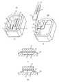
図1は、本発明の第1の実施の形態に係る角速度センサ100を示す図である。図1(A)は角速度センサ100の斜視図、図1(B)は角速度センサ100の分解斜視図、図1(C)は図1(A)に示すA−A線要部断面図、図1(D)は、図1(A)に示すA−A線要部断面図であって、図1(C)とは異なる形態を示す図である。
Hereinafter, embodiments of the present invention will be described in detail with reference to the accompanying drawings.
(First embodiment)
FIG. 1 is a diagram showing anangular velocity sensor 100 according to the first embodiment of the present invention. 1A is a perspective view of theangular velocity sensor 100, FIG. 1B is an exploded perspective view of theangular velocity sensor 100, and FIG. 1C is a cross-sectional view taken along line AA in FIG. 1 (D) is a cross-sectional view taken along the line AA in FIG. 1 (A) and shows a different form from FIG. 1 (C).

これらの図に示す角速度センサ100は、音叉型振動子10、単一のリードフレーム20、及びセラミックスで形成されたパッケージ30を有する。音叉型振動子10はベース13と、ベース13から同一方向に伸びる離間配置された2つのアーム11、12とを有する。リードフレーム20はベース13を支持する作用を持ち、その平面形状はコの字である。コの字とは、コの字又は基本となる形状がコの字であることを意味し、厳密に「コ」の字状である必要はない。コの字ではなく、C字状と言ってもよい。つまり、リードフレーム20は、中心部分とこの中心部分の両端部から同一側に延びる2つの部分とを有する。音叉型振動子10のベース13を支持するリードフレーム20は、図1(C)に示す形態、図1(D)に示す形態及び図5に示す形態のものがある。またリードフレーム20の形態に応じて、パッケージ30も図1(C)に示す形態と、図1(D)に示す形態とがある。  Theangular velocity sensor 100 shown in these drawings includes atuning fork vibrator 10, asingle lead frame 20, and apackage 30 formed of ceramics. Thetuning fork vibrator 10 includes abase 13 and twoarms 11 and 12 that are spaced apart from each other and extend in the same direction from thebase 13. Thelead frame 20 has a function of supporting thebase 13, and its planar shape is a U-shape. The U-shape means that the U-shape or the basic shape is a U-shape, and does not have to be exactly “U” -shape. It may be said that it is C-shaped instead of U-shaped. That is, thelead frame 20 has a central portion and two portions extending on the same side from both ends of the central portion. Thelead frame 20 that supports thebase 13 of the tuningfork type vibrator 10 has a form shown in FIG. 1C, a form shown in FIG. 1D, and a form shown in FIG. Depending on the form of thelead frame 20, thepackage 30 may be of the form shown in FIG. 1C and the form shown in FIG.

図1(C)に示す形態では、リードフレーム20は平板状であって、ベース13を支持する平坦部21を有する。リードフレーム20を支持するパッケージ30の面(底面)には、凹部31が形成されている。リードフレーム20の平坦部21の下方には、パッケージ30の凹部31で形成された空間が設けられている。つまり、パッケージ30とリードフレーム20との間に空間31が形成されている。図1(C)の構成では、空間31の幅は、ベース13の幅と略等しい。空間31は、リードフレーム20の剛性を緩和してリードフレーム20にバネ性を持たせ、音叉型振動子10の振動をパッケージ30に伝わり難くすることができる。これにより、パッケージ30を配線基板などに固定したときの周波数変動を抑制することができる。リードフレーム20を用いて、空間31上にベース13を支持する構成は、パッケージ30からの振動(外乱ノイズ)を音叉型振動子10に伝わり難くする作用効果も持つ。  In the form shown in FIG. 1C, thelead frame 20 has a flat plate shape and has aflat portion 21 that supports thebase 13. Arecess 31 is formed on the surface (bottom surface) of thepackage 30 that supports thelead frame 20. A space formed by therecess 31 of thepackage 30 is provided below theflat portion 21 of thelead frame 20. That is, aspace 31 is formed between thepackage 30 and thelead frame 20. In the configuration of FIG. 1C, the width of thespace 31 is substantially equal to the width of thebase 13. Thespace 31 can relieve the rigidity of thelead frame 20 to provide thelead frame 20 with a spring property so that the vibration of thetuning fork vibrator 10 is not easily transmitted to thepackage 30. Thereby, frequency fluctuations when thepackage 30 is fixed to a wiring board or the like can be suppressed. The configuration in which thebase 13 is supported on thespace 31 using thelead frame 20 also has an effect of making it difficult for vibration (disturbance noise) from thepackage 30 to be transmitted to thetuning fork vibrator 10.

図2は、空間31の作用効果を示す図である。図2には、比較例として、図1(C)を変形して空間31を設けない場合の特性も示す。図2の横軸は空間の有無を示し、縦軸はパッケージ30をある部材に固定した場合の周波数変動量(%)を示す。単一のリードフレーム20を設け、その下に空間31を設けたことで、振動周波数の変動が抑制されることが分かる。  FIG. 2 is a diagram illustrating the effect of thespace 31. FIG. 2 also shows characteristics when thespace 31 is not provided by modifying FIG. 1C as a comparative example. The horizontal axis in FIG. 2 indicates the presence or absence of space, and the vertical axis indicates the amount of frequency variation (%) when thepackage 30 is fixed to a certain member. It can be seen that the fluctuation of the vibration frequency is suppressed by providing thesingle lead frame 20 and providing thespace 31 thereunder.

図3は、ベース部13の自由長(非固定エリア)と周波数変化率との関係を示す図である。図3の横軸は自由長をアーム11、12の幅に対する比で表示し、縦軸は自由長2.5を基準にした場合の周波数変化率(%)を示す。なお、自由長とは、図4に示すようにベース13を、リードフレーム20に固定する固定部と、固定しない非固定部とに分けたときの非固定部の長さを示す。図3に示すようにベース部13の自由長2.0以下では周波数変化率が急激になり実装ばらつき増加の要因となるため、自由長は2.0以上とすることで実装ばらつきを抑制できることが分かる。  FIG. 3 is a diagram showing the relationship between the free length (non-fixed area) of thebase portion 13 and the frequency change rate. The horizontal axis in FIG. 3 represents the free length as a ratio to the width of thearms 11 and 12, and the vertical axis represents the frequency change rate (%) when the free length is 2.5 as a reference. The free length indicates the length of the non-fixed portion when thebase 13 is divided into a fixed portion that is fixed to thelead frame 20 and a non-fixed portion that is not fixed, as shown in FIG. As shown in FIG. 3, when the free length of thebase portion 13 is 2.0 or less, the frequency change rate becomes abrupt and causes an increase in mounting variation. Therefore, mounting variation can be suppressed by setting the free length to 2.0 or more. I understand.

また、図1(D)に示すリードフレーム20は、断面がコの字状の屈曲部22を有する。この屈曲部22はベース13を支持する。屈曲部22は空間31を形成する。図1(D)に示す屈曲部22の対向する部分は垂直に形成されているが、傾斜していてもよい。パッケージ30の底面は、図1(C)の形態とは異なり、平坦である。図1(B)に示されるリードフレーム20は、図1(D)の形態を持っている。屈曲部22は、ベース13との接触部全体を接着している。図1(C)や図1(D)において、リードフレーム20とベース13とは、例えばエポキシ系樹脂の接着剤で固定される。この固定は、高い生産性を持って行える。  Thelead frame 20 shown in FIG. 1D has abent portion 22 having a U-shaped cross section. Thebent portion 22 supports thebase 13. Thebent portion 22 forms aspace 31. The opposing portions of thebent portion 22 shown in FIG. 1D are formed vertically, but may be inclined. Unlike the form of FIG. 1C, the bottom surface of thepackage 30 is flat. Alead frame 20 shown in FIG. 1B has the form shown in FIG. Thebent portion 22 bonds the entire contact portion with thebase 13. In FIG. 1C and FIG. 1D, thelead frame 20 and the base 13 are fixed with, for example, an epoxy resin adhesive. This fixing can be performed with high productivity.

リードフレーム20は、その他の形態として、図5(A)〜図5(H)に示す構成であってもよい。図5(A)に示すリードフレーム20は、断面が台形状の屈曲部22を有している。また図5(B)に示すリードフレーム20は、断面がM字状の屈曲部22を有している。台形状のリードフレーム20は、ベース13を支持する平坦部24からパッケージ30までのリードフレーム20の長さが、コの字状のリードフレーム20よりも長いL1で形成されている。同様に、M字状のリードフレーム20は、平坦部24を支える支柱部分の長さが、コの字状のリードフレーム20よりも長いL2で形成されている。  As another form, thelead frame 20 may have the configuration shown in FIGS. 5 (A) to 5 (H). Alead frame 20 shown in FIG. 5A has abent portion 22 having a trapezoidal cross section. Thelead frame 20 shown in FIG. 5B has abent portion 22 having an M-shaped cross section. Thetrapezoidal lead frame 20 is formed by L1 in which the length of thelead frame 20 from theflat portion 24 supporting the base 13 to thepackage 30 is longer than theU-shaped lead frame 20. Similarly, the M-shapedlead frame 20 is formed with L2 in which the length of the column portion supporting theflat portion 24 is longer than that of theU-shaped lead frame 20.

また、図5(C)、(E)、(G)に示すリードフレーム20は、ベース13を支持する平坦部24に、L字状の折り返し部23を設けている。L字状の折り返し部23を設けることによって、ベース13を指示するリードフレームの支持面積が増え、接着強度が向上する。なお、図5(D)は、図5(C)に示すリードフレーム20だけを示す斜視図であり、図5(F)は、図5(E)に示すリードフレーム20だけを示す斜視図であり、図5(H)は、図5(G)に示すリードフレームだけを示す斜視図である。  In addition, thelead frame 20 shown in FIGS. 5C, 5 </ b> E, and 5 </ b> G has an L-shaped foldedportion 23 in aflat portion 24 that supports thebase 13. Providing the L-shaped foldedportion 23 increases the support area of the lead frame that points to thebase 13 and improves the adhesive strength. 5 (D) is a perspective view showing only thelead frame 20 shown in FIG. 5 (C), and FIG. 5 (F) is a perspective view showing only thelead frame 20 shown in FIG. 5 (E). FIG. 5 (H) is a perspective view showing only the lead frame shown in FIG. 5 (G).

図6は、断面が台形状およびM字状リードフレーム20の作用効果を示す図である。図6には、比較例として、図1(D)のコの字状リードフレーム20の特性も示す。図6の横軸は単一のリードフレーム形状を示し、縦軸はパッケージ30をある部材に固定した場合の音叉型振動子10のインピーダンス(Zy)変動量(kΩ)を示す。台形状およびM字状リードフレーム20は、屈曲部22からパッケージ33までのリードフレーム部分の長さ(L1,L2)が、コの字状リードフレーム20より長くできることで、バネ性が向上し、インピーダンス変動が抑制されていることが分かる。  FIG. 6 is a diagram showing the operational effects of the trapezoidal and M-shapedlead frame 20 in cross section. FIG. 6 also shows characteristics of theU-shaped lead frame 20 of FIG. 1D as a comparative example. The horizontal axis of FIG. 6 shows a single lead frame shape, and the vertical axis shows the impedance (Zy) variation (kΩ) of thetuning fork vibrator 10 when thepackage 30 is fixed to a certain member. The trapezoidal and M-shapedlead frame 20 has a longer length (L1, L2) of the lead frame portion from thebent portion 22 to thepackage 33 than theU-shaped lead frame 20, thereby improving the spring property. It can be seen that the impedance variation is suppressed.

好ましくは、リードフレーム20を、音叉型振動子10の材質の熱膨張係数と近い熱膨張係数を持つ材質で形成するとよい。例えば、音叉型振動子10をリチウムナイオベート(熱膨張係数は15.4×10⁻⁶/°C)で形成した場合、リードフレーム20をSUS(熱膨張係数は17.3×10−6/°C)やリン青銅(熱膨張係数は17.8×10−6/°C)で形成する。また、パッケージ30を熱膨張係数が7.8×10−6/°Cのアルミナ(Al23)で形成する。パッケージ30は、複数のセラミック基板を多層に積層した構成が好ましい。パッケージ30は、層間に形成された配線層は、異なる層に形成された配線層を接続するビアなどを含む。Preferably, thelead frame 20 is formed of a material having a thermal expansion coefficient close to that of the material of thetuning fork vibrator 10. For example, when thetuning fork vibrator 10 is made of lithium niobate (coefficient of thermal expansion is 15.4 × 10⁻⁶ / ° C.), thelead frame 20 is made of SUS (coefficient of thermal expansion is 17.3 × 10⁻⁶ / ° C) or phosphor bronze (thermal expansion coefficient is 17.8 × 10⁻⁶ / ° C.). Thepackage 30 is made of alumina (Al2 O3 ) having a thermal expansion coefficient of 7.8 × 10⁻⁶ / ° C. Thepackage 30 preferably has a configuration in which a plurality of ceramic substrates are stacked in multiple layers. In thepackage 30, the wiring layers formed between the layers include vias that connect the wiring layers formed in different layers.

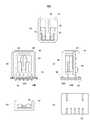
次に、音叉型振動子10について説明する。音叉型振動子10には、図7(A)及び(B)に示す電極が形成されている。図7(A)は音叉型振動子10の表側を示し、図7(B)は裏側を示す。アーム11には検出電極11a、11b、11cが設けられている。検出電極11aと11bは電極11dで接続されている。検出電極11aには引出し電極11fが設けられている。電極11cは、引出し電極11eに接続されている。同様に、アーム12には、検出電極12a、12b、12cが設けられている。検出電極12aと12bは電極12dで接続されている。電極12aには引出し電極12fが設けられている。電極12cは、引出し電極12eに接続されている。音叉型振動子10の表面には駆動電極14aが設けられ、引出し電極14bに接続されている。同様に、裏面には駆動電極15aが設けられ、引出し電極15bに接続されている。なお、図7に示す音叉型振動子10のベース13の形状が図1に示すものと若干異なっている。図7に示すベース13は、図1に示すベースの変形例である。図1に示すベース13は幅広部分を有し、この部分に前述したリードフレーム20が取り付けられる。図7に示すベース13の幅は均一で、リードフレーム20に対し検出軸方向の任意の位置に位置決めすることができる。  Next, thetuning fork vibrator 10 will be described. Thetuning fork vibrator 10 is formed with electrodes shown in FIGS. 7A and 7B. 7A shows the front side of thetuning fork vibrator 10, and FIG. 7B shows the back side. Thearm 11 is provided withdetection electrodes 11a, 11b, and 11c. Thedetection electrodes 11a and 11b are connected by anelectrode 11d. Thedetection electrode 11a is provided with anextraction electrode 11f. Theelectrode 11c is connected to theextraction electrode 11e. Similarly, thearm 12 is provided withdetection electrodes 12a, 12b, and 12c. Thedetection electrodes 12a and 12b are connected by anelectrode 12d. Theelectrode 12a is provided with alead electrode 12f. Theelectrode 12c is connected to theextraction electrode 12e. A drivingelectrode 14a is provided on the surface of thetuning fork vibrator 10, and is connected to theextraction electrode 14b. Similarly, adrive electrode 15a is provided on the back surface and connected to theextraction electrode 15b. The shape of thebase 13 of thetuning fork vibrator 10 shown in FIG. 7 is slightly different from that shown in FIG. A base 13 shown in FIG. 7 is a modification of the base shown in FIG. The base 13 shown in FIG. 1 has a wide portion, and the above-describedlead frame 20 is attached to this portion. The base 13 shown in FIG. 7 has a uniform width and can be positioned at any position in the detection axis direction with respect to thelead frame 20.

図7に示す引出し電極は、例えば図8(A)に示すように、ワイヤ42を用いてパッケージ30に設けられたパッド(端子)32にボンディングされる。パッド32はバンク33上に形成されており、パッケージ30に設けられた配線に接続されている。ここで、図8(A)は角速度センサ100の平面図、図8(B)は断面図、図8(C)は底面図である。パッケージ30の上面は開放されており、リング状に形成されたパッケージ30の取り付け面には外部接続パッド(端子)34が形成されている。外部接続パッド34は、パッケージ30内部の配線を介して、音叉型振動子10の各電極に接続されている。パッケージ30の底面には、パッケージ30内部の配線に接続される外部接続パッド(端子)35が形成されている。なお、図8(A)〜(C)には座標軸X、Y、Zが示されており、角速度センサ100はY軸を中心とする角速度ωyを検出する。  The extraction electrode shown in FIG. 7 is bonded to a pad (terminal) 32 provided on thepackage 30 by using awire 42 as shown in FIG. Thepad 32 is formed on thebank 33 and connected to the wiring provided on thepackage 30. 8A is a plan view of theangular velocity sensor 100, FIG. 8B is a cross-sectional view, and FIG. 8C is a bottom view. The upper surface of thepackage 30 is open, and external connection pads (terminals) 34 are formed on the mounting surface of thepackage 30 formed in a ring shape. Theexternal connection pad 34 is connected to each electrode of thetuning fork vibrator 10 via wiring inside thepackage 30. On the bottom surface of thepackage 30, external connection pads (terminals) 35 connected to wiring inside thepackage 30 are formed. 8A to 8C show coordinate axes X, Y, and Z, and theangular velocity sensor 100 detects an angular velocity ωy centered on the Y axis.

(第2の実施の形態)
図9及び図10は、本発明の第2の実施の形態に係る角速度センサ200を説明するための図である。この角速度センサ200は、第1の実施の形態に係る角速度センサ100を2つ用い(以下100Aと100Bとする)、2軸方向を中心とする角速度を検出する構成である。
(Second Embodiment)
9 and 10 are views for explaining anangular velocity sensor 200 according to the second embodiment of the present invention. Thisangular velocity sensor 200 uses twoangular velocity sensors 100 according to the first embodiment (hereinafter referred to as “100A” and “100B”) and detects an angular velocity centered on a biaxial direction.

図9(A)は角速度センサ100A、100Bを搭載する回路基板50の平面図、図9(B)は側面図、及び図9(C)は底面図である。また、図10(A)は第1の実施の形態に係る2つの角速度センサ100A、100B(以下、角速度センサ部品と呼ぶ)を回路基板50に搭載した角速度センサ200の平面図、図10(B)は側面図(パッケージ30内部を透視した状態で図示してある)、及び図10(C)は底面図である。図10(A)に示すように、角速度センサ部品100A、100BはそれぞれX軸方向及びY軸方向を中心とする角速度が検出できるように、回路基板50上に配置される。回路基板50は、角速度センサ100A、100Bの共通に設けられている。図10(B)に示すように、角速度センサ部品100A、100Bの開口面を下にして、角速度センサ部品100A、100Bを回路基板50に取り付ける。つまり、角速度センサ部品100A、100Bは、これらに共通の回路基板50で封止される。図9(A)に示すように、回路基板50には、角速度センサ部品100A、100Bの外部接続パッド34(図8(A))と電気的に接続されるパッド(端子)51が設けられている。この接続には、例えばペースト状の異方導電性接着剤が用いられる。  9A is a plan view of thecircuit board 50 on which theangular velocity sensors 100A and 100B are mounted, FIG. 9B is a side view, and FIG. 9C is a bottom view. FIG. 10A is a plan view of anangular velocity sensor 200 in which twoangular velocity sensors 100A and 100B (hereinafter referred to as angular velocity sensor components) according to the first embodiment are mounted on thecircuit board 50, and FIG. ) Is a side view (shown in a state where the inside of thepackage 30 is seen through), and FIG. 10C is a bottom view. As shown in FIG. 10A, the angularvelocity sensor components 100A and 100B are arranged on thecircuit board 50 so that angular velocities around the X-axis direction and the Y-axis direction can be detected. Thecircuit board 50 is provided in common to theangular velocity sensors 100A and 100B. As shown in FIG. 10B, the angularvelocity sensor components 100A and 100B are attached to thecircuit board 50 with the opening surfaces of the angularvelocity sensor components 100A and 100B facing down. That is, the angularvelocity sensor components 100A and 100B are sealed with thecircuit board 50 common to them. As shown in FIG. 9A, thecircuit board 50 is provided with pads (terminals) 51 that are electrically connected to the external connection pads 34 (FIG. 8A) of the angularvelocity sensor components 100A and 100B. Yes. For this connection, for example, a paste-like anisotropic conductive adhesive is used.

図11に示すように、異方導電性接着剤57を回路基板50上に設け、角速度センサ部品100A、100Bを接着固定する。異方導電性接着剤57の作用により、角速度センサ部品100A、100Bと回路基板50との電気的接続が形成される。  As shown in FIG. 11, an anisotropic conductive adhesive 57 is provided on thecircuit board 50, and the angularvelocity sensor components 100A and 100B are bonded and fixed. By the action of the anisotropic conductive adhesive 57, the angularvelocity sensor components 100A and 100B and thecircuit board 50 are electrically connected.

図9(A)に戻り、パッド51の配列は、パッド34の配列に符合している。パッド51で取り囲まれる回路基板50上の領域は部品搭載領域52となり、矩形で図示された電子部品(例えば、抵抗やコンデンサなど)が回路基板50に取り付けられている。図10(B)に示すように、部品搭載領域52内の電子部品は、角速度センサ部品100A、100Bのパッケージ30で封止されている。回路基板50は単層又は多層構成である。また、回路基板50上には、別の部品搭載領域53やIC搭載領域54が設けられている。IC搭載領域54は1つ又は複数のICを搭載することができる。回路基板50の4辺にはキャスタレーション55(接続路)が形成されており、回路基板50の底面(図9(C)、図10(C))には、キャスタレーションと一体に形成された外部接続パッドが設けられている。記号Vccは電源電圧、GNDはグランド、2つの角速度センサ部品100A、100BのVref1、Vref2は基準電圧、Vout1、Vout2は2つの角速度センサ部品100A、100Bの出力電圧である。キャスタレーション55はそれぞれ、音叉型振動子10の対応する電極に接続されている。  Returning to FIG. 9A, the arrangement of thepads 51 matches the arrangement of thepads 34. An area on thecircuit board 50 surrounded by thepad 51 is acomponent mounting area 52, and electronic components (for example, resistors, capacitors, etc.) illustrated in a rectangle are attached to thecircuit board 50. As shown in FIG. 10B, the electronic components in thecomponent mounting area 52 are sealed with thepackages 30 of the angularvelocity sensor components 100A and 100B. Thecircuit board 50 has a single layer or multilayer structure. Further, anothercomponent mounting area 53 and anIC mounting area 54 are provided on thecircuit board 50. TheIC mounting area 54 can mount one or a plurality of ICs. A castellation 55 (connection path) is formed on four sides of thecircuit board 50, and the bottom surface (FIGS. 9C and 10C) of thecircuit board 50 is formed integrally with the castellation. External connection pads are provided. Symbol Vcc is a power supply voltage, GND is ground, Vref1 and Vref2 of the two angularvelocity sensor components 100A and 100B are reference voltages, and Vout1 and Vout2 are output voltages of the two angularvelocity sensor components 100A and 100B. Eachcastellation 55 is connected to a corresponding electrode of thetuning fork vibrator 10.

角速度センサ部品100A、100Bは第1の実施の形態に係る構成を有しているので、回路基板50に実装される前後で発生する周波数変動を抑制することができ、高い精度の2軸角速度センサを提供することができる。また、1つの回路基板50を2つの角速度センサ100A、100Bに共通に設けたため、小型化が可能になる。  Since the angularvelocity sensor components 100A and 100B have the configuration according to the first embodiment, it is possible to suppress frequency fluctuations occurring before and after being mounted on thecircuit board 50, and a highly accurate biaxial angular velocity sensor. Can be provided. In addition, since onecircuit board 50 is provided in common for the twoangular velocity sensors 100A and 100B, the size can be reduced.

(第3の実施の形態)
図12は、第3の実施の形態に係る角速度センサ300を示す図である。この角速度センサ300は、3軸方向の角速度を検出できる角速度センサである。図12(A)は角速度センサ300の平面図、図12(B)は側面図(パッケージ30内部を透視した状態で図示してある)である。図12(A)、(B)に示す角速度センサ300は、前述の角速度センサ200に加え、新たに角速度センサ部品100CをIC搭載領域54(図9(A))に設けたものである。角速度センサ部品100Cは、Z軸を中心とする角速度を検出するために、音叉型振動子10が回路基板50に垂直な方向となるように、回路基板50上に搭載されている。角速度センサ部品100Cのパッケージ30の短手方向側面にパッドを設け、回路基板50との電気的及び機械的接続を行ってもよいし、後述する縦型の角速度センサを用いることもできる。角速度センサ部品100Cのパッケージ30の開口面にはキャップ101が設けられ、内部を封止している。
(Third embodiment)
FIG. 12 is a diagram showing anangular velocity sensor 300 according to the third embodiment. Thisangular velocity sensor 300 is an angular velocity sensor that can detect angular velocities in three axial directions. 12A is a plan view of theangular velocity sensor 300, and FIG. 12B is a side view (shown in a state where the inside of thepackage 30 is seen through). Anangular velocity sensor 300 shown in FIGS. 12A and 12B is obtained by newly providing an angular velocity sensor component 100C in the IC mounting region 54 (FIG. 9A) in addition to theangular velocity sensor 200 described above. The angularvelocity sensor component 100 </ b> C is mounted on thecircuit board 50 so that thetuning fork vibrator 10 is in a direction perpendicular to thecircuit board 50 in order to detect an angular velocity centered on the Z axis. A pad may be provided on the lateral side surface of thepackage 30 of the angular velocity sensor component 100C to make electrical and mechanical connection with thecircuit board 50, or a vertical angular velocity sensor described later may be used. Acap 101 is provided on the opening surface of thepackage 30 of the angular velocity sensor component 100C to seal the inside.

角速度センサ部品100A、100B、100Cは第1の実施の形態に係る構成を有しているので、回路基板50に実装される前後での周波数変動を抑制することができ、高い精度の3軸角速度センサを提供することができる。また、1つの回路基板50を3つの角速度センサ100A、100B、100Cに共通に設けたため、小型化が可能になる。  Since the angularvelocity sensor components 100A, 100B, and 100C have the configuration according to the first embodiment, the frequency fluctuation before and after being mounted on thecircuit board 50 can be suppressed, and the highly accurate triaxial angular velocity. A sensor can be provided. Further, since onecircuit board 50 is provided in common for the threeangular velocity sensors 100A, 100B, and 100C, the size can be reduced.

ここで、回路基板50上のパッド51の配列について説明する。図9(A)に示すパッド51の配列は、X軸及びY軸を中心とする角速度を検出できるように決定されている。このパッド51は、図13(A)や(B)に示すように、角速度センサ部品100A、100BがX軸方向及び/又はY軸方向に対して所定の角度θだけ傾斜するような配置とすることができる。図13(A)は、角速度センサ部品100A、100Bの両方をθだけ傾斜させる場合のパッド51の配列を示し、図13(B)は角速度センサ100Bだけをθだけ傾斜させる場合のパッド51の配置を示す。このように、パッド51の配置のみで角速度検出軸を任意に簡単かつ任意に調整することができる。  Here, the arrangement of thepads 51 on thecircuit board 50 will be described. The arrangement of thepads 51 shown in FIG. 9A is determined so that angular velocities around the X axis and the Y axis can be detected. As shown in FIGS. 13A and 13B, thepad 51 is arranged such that the angularvelocity sensor components 100A and 100B are inclined by a predetermined angle θ with respect to the X-axis direction and / or the Y-axis direction. be able to. FIG. 13A shows the arrangement ofpads 51 when both angularvelocity sensor components 100A and 100B are inclined by θ, and FIG. 13B shows the arrangement ofpads 51 when onlyangular velocity sensor 100B is inclined by θ. Indicates. As described above, the angular velocity detection axis can be arbitrarily and simply adjusted by simply arranging thepads 51.

(第4の実施の形態)
図14は、第4の実施の形態に係る角速度センサ400を示す図である。この角速度センサ400は、前述した図8に示す角速度センサ100をキャップ内に封止し、角速度センサ400の取り付け面に対して垂直方向に音叉型振動子10を保持する構成である。図14(A)は図8(A)に示す角速度センサ100を示す平面図、図14(B)は角速度センサ100を内部に含む角速度センサ400の正面図(内部を透視した状態で図示してある)、図14(C)はその側面図、図14(D)は角速度センサ100の側面図、及び図14(E)は角速度センサ400の底面図である。
(Fourth embodiment)
FIG. 14 is a diagram showing anangular velocity sensor 400 according to the fourth embodiment. Theangular velocity sensor 400 has a configuration in which theangular velocity sensor 100 shown in FIG. 8 is sealed in a cap and thetuning fork vibrator 10 is held in a direction perpendicular to the mounting surface of theangular velocity sensor 400. 14A is a plan view showing theangular velocity sensor 100 shown in FIG. 8A, and FIG. 14B is a front view of theangular velocity sensor 400 including theangular velocity sensor 100 inside (illustrated in a state where the inside is seen through). 14C is a side view thereof, FIG. 14D is a side view of theangular velocity sensor 100, and FIG. 14E is a bottom view of theangular velocity sensor 400.

角速度センサ400は、パッケージ30を支持する回路基板60と、角速度センサ400の実装面に対して回路基板60を垂直に支持する支持基板64とを有する。パッケージ30の開口面は回路基板60に取り付けられている。回路基板60上には電子部品62が搭載され、パッケージ30はこの電子部品62を覆うように位置決めされている。回路基板60の背面にも電子部品66が設けられている。音叉型振動子10は、電子部品62に対向している。回路基板60は支持基板64に支持されており、音叉型振動子10の検出軸は支持基板64に垂直な方向に一致する。支持基板64は、ステム64Aと、回路基板の一つであるプリント基板64Bと、外部接続ピン65とを有する。外部接続ピン65は一部を除き、回路基板60の背面に設けられたパッドに接続されており、回路基板60に形成された配線を介して音叉型振動子10の電極に接続されている。外部接続ピン65はステム64A及びプリント基板64Bを貫通し、プリント基板64Bの底面中央部から端部に向かって両方向(プリント基板64Bの短手方向)に延びている。プリント基板64Bは多層構成である。キャップ68はパッケージ30、回路基板60、ステム64Aを覆うように角速度センサ400の内部を気密封止する。キャップ68は例えば接着剤を用いてプリント基板64Bに固定される。  Theangular velocity sensor 400 includes acircuit board 60 that supports thepackage 30 and asupport board 64 that supports thecircuit board 60 perpendicular to the mounting surface of theangular velocity sensor 400. The opening surface of thepackage 30 is attached to thecircuit board 60. Anelectronic component 62 is mounted on thecircuit board 60, and thepackage 30 is positioned so as to cover theelectronic component 62. Anelectronic component 66 is also provided on the back surface of thecircuit board 60. Thetuning fork vibrator 10 faces theelectronic component 62. Thecircuit board 60 is supported by asupport board 64, and the detection axis of thetuning fork vibrator 10 coincides with a direction perpendicular to thesupport board 64. Thesupport substrate 64 includes astem 64A, a printedcircuit board 64B that is one of circuit boards, and external connection pins 65. Theexternal connection pin 65 is connected to a pad provided on the back surface of thecircuit board 60 except for a part thereof, and is connected to an electrode of thetuning fork vibrator 10 through a wiring formed on thecircuit board 60. Theexternal connection pin 65 penetrates thestem 64A and the printedcircuit board 64B, and extends in both directions (short direction of the printedcircuit board 64B) from the center of the bottom surface of the printedcircuit board 64B toward the end. The printedcircuit board 64B has a multilayer structure. Thecap 68 hermetically seals the inside of theangular velocity sensor 400 so as to cover thepackage 30, thecircuit board 60, and thestem 64A. Thecap 68 is fixed to the printedcircuit board 64B using, for example, an adhesive.

角速度センサ100を用いているので、回路基板60に実装される前後での周波数変動を抑制することができ、高い精度の角速度センサを提供することができる。なお、この角速度センサ400を図12に示す角速度センサ100Cとして用いることができる。  Since theangular velocity sensor 100 is used, frequency fluctuations before and after being mounted on thecircuit board 60 can be suppressed, and a highly accurate angular velocity sensor can be provided. Theangular velocity sensor 400 can be used as the angular velocity sensor 100C shown in FIG.

(第5の実施の形態) 図15は、本発明の第5の実施の形態に係る角速度センサ500を示す図である。この角速度センサ500は、前述した図8に示す角速度センサ100を備え、角速度センサ400の取り付け面に対して垂直方向に音叉型振動子10を保持する構成である。図15(A)は角速度センサ500の平面図、図15(B)は角速度センサ500の正面図(内部を透視した状態で図示してある)、図15(C)はその側面図、及び図15(D)は角速度センサ500の底面図である。角速度センサ100は、モールドで形成された支持基板74に取り付けられている。回路基板70も同様に支持基板74に取り付けられている。角速度センサ100と回路基板70とは離間している。角速度センサ100のパッケージ30の背面には複数のパッド19が設けられている。このパッド19は、パッケージ30内の配線を介して、内部の音叉型振動子10の電極に接続されている。パッド19には、ピン状の接続部材72が接続されている。接続部材72は、電子部品66が設けられている回路基板70の一方の面に延びており、この面に形成されているパッドに接続されている。回路基板70の他方の面にも電子部品62が取り付けられている。電子部品62はパッケージ30に面している。支持基板74には接続ピン75が取り付けられており、一部を除いて回路基板70上のパッドに電気的に接続されている。接続ピン75を介して、外部と音叉型振動子10との接続を形成することができる。Fifth Embodiment FIG. 15 is a diagram showing anangular velocity sensor 500 according to a fifth embodiment of the present invention. Theangular velocity sensor 500 includes theangular velocity sensor 100 shown in FIG. 8 described above, and is configured to hold thetuning fork vibrator 10 in a direction perpendicular to the mounting surface of theangular velocity sensor 400. 15A is a plan view of theangular velocity sensor 500, FIG. 15B is a front view of the angular velocity sensor 500 (illustrated in a transparent state), FIG. 15C is a side view thereof, and FIG. 15 (D) is a bottom view of theangular velocity sensor 500. Theangular velocity sensor 100 is attached to asupport substrate 74 formed of a mold. Thecircuit board 70 is similarly attached to thesupport board 74. Theangular velocity sensor 100 and thecircuit board 70 are separated from each other. A plurality ofpads 19 are provided on the back surface of thepackage 30 of theangular velocity sensor 100. Thepad 19 is connected to an electrode of thetuning fork vibrator 10 inside through a wiring in thepackage 30. A pin-shaped connectingmember 72 is connected to thepad 19. Theconnection member 72 extends to one surface of thecircuit board 70 on which theelectronic component 66 is provided, and is connected to a pad formed on this surface. Anelectronic component 62 is also attached to the other surface of thecircuit board 70. Theelectronic component 62 faces thepackage 30. Connection pins 75 are attached to thesupport substrate 74 and are electrically connected to pads on thecircuit board 70 except for a part. A connection between the outside and thetuning fork vibrator 10 can be formed via theconnection pin 75.

角速度センサ100を用いたことにより、回路基板70に実装される前後での周波数変動を抑制することができ、高い精度の角速度センサを提供することができる。  By using theangular velocity sensor 100, frequency fluctuations before and after being mounted on thecircuit board 70 can be suppressed, and a highly accurate angular velocity sensor can be provided.

(第6の実施の形態)
図16は、第6の実施の形態に係る角速度センサ600を示す図である。図16(A)は角速度センサ600の平面図、図16(B)は側面図(内部を透視した状態で図示してある)である。この実施例では、1つのパッケージ130内に2つの音叉型振動子10A、10Bを収納している。音叉型振動子10A、10Bはそれぞれ直交する方向に配置されている。音叉型振動子10A、10Bは前述した音叉型振動子10と同一構成であって、それぞれ単一のリードフレーム120A、120Bにより支持されている。音叉型振動子10A、10Bとリードフレーム120A、120Bとからなる構成をそれぞれユニットと定義する。リードフレーム120A、120Bは直線状の平面形状を有し、コの字状の断面形状を有する。コの字状の断面形状は、図1(D)に示すリードフレーム20と同様に、リードフレームを屈曲させることで形成されている。この屈曲部がリードフレーム120A、120Bとパッケージ130の底面との間に空間を形成する。音叉型振動子10A、10Bはワイヤにより、パッケージ130内のバンク131、132上に設けられたパッドに接続されている。なお、図示を省略しているが、パッケージ130の開口面に、例えば金属製のキャップを取り付け、パッケージ内部を気密封止することができる。
(Sixth embodiment)
FIG. 16 is a diagram showing anangular velocity sensor 600 according to the sixth embodiment. 16A is a plan view of theangular velocity sensor 600, and FIG. 16B is a side view (shown in a state where the inside is seen through). In this embodiment, twotuning fork vibrators 10A and 10B are accommodated in onepackage 130. Thetuning fork vibrators 10A and 10B are arranged in directions orthogonal to each other. Thetuning fork vibrators 10A and 10B have the same configuration as thetuning fork vibrator 10 described above, and are supported by asingle lead frame 120A and 120B, respectively. A configuration composed of tuningfork vibrators 10A and 10B andlead frames 120A and 120B is defined as a unit. The lead frames 120A and 120B have a linear planar shape and a U-shaped cross-sectional shape. The U-shaped cross-sectional shape is formed by bending the lead frame similarly to thelead frame 20 shown in FIG. This bent portion forms a space between the lead frames 120A and 120B and the bottom surface of thepackage 130. Thetuning fork vibrators 10A and 10B are connected to pads provided on thebanks 131 and 132 in thepackage 130 by wires. Although not shown, for example, a metal cap can be attached to the opening surface of thepackage 130 to hermetically seal the inside of the package.

上記構成のユニットを用いたことにより、角速度センサ600を回路基板に実装する前後で発生する周波数変動を抑制することができ、高い精度の2軸角速度センサを提供することができる。また、音叉型振動子10A、10Bがパッケージ130を介して干渉することを効果的に防止することができ、小型でありながら高い精度で2軸まわりの角速度を検出することができるようになる。  By using the unit configured as described above, it is possible to suppress frequency fluctuations that occur before and after mounting theangular velocity sensor 600 on the circuit board, and to provide a highly accurate biaxial angular velocity sensor. Further, thetuning fork vibrators 10A and 10B can be effectively prevented from interfering with each other via thepackage 130, and the angular velocity around two axes can be detected with high accuracy while being small in size.

図17は、第6の実施の形態を変形した構成を有する角速度センサ700を示す図である。図17(A)は角速度センサ600の平面図、図17(B)は側面図(内部を透視した状態で図示してある)である。角速度センサ700の音叉型振動子10A、10Bはそれぞれ、平坦な直線状のリードフレーム120C、120Dで支持されている。リードフレーム120C、120はそれぞれ一対の突起部133、134上に取り付けられている。この突起部133、134がリードフレーム120C、120Dとパッケージ130の底面との間に空間を形成する。従って、角速度センサ700を回路基板に実装する前後で発生する周波数変動を抑制することができ、高い精度の2軸角速度センサを提供することができる。  FIG. 17 is a diagram showing anangular velocity sensor 700 having a configuration obtained by modifying the sixth embodiment. 17A is a plan view of theangular velocity sensor 600, and FIG. 17B is a side view (shown in a state where the inside is seen through). Thetuning fork vibrators 10A and 10B of theangular velocity sensor 700 are supported by flat linear lead frames 120C and 120D, respectively. Lead frames 120C and 120 are mounted on a pair ofprotrusions 133 and 134, respectively. Theprotrusions 133 and 134 form a space between the lead frames 120C and 120D and the bottom surface of thepackage 130. Therefore, it is possible to suppress the frequency fluctuation that occurs before and after mounting theangular velocity sensor 700 on the circuit board, and to provide a highly accurate biaxial angular velocity sensor.

(第7の実施の形態)
図18は、第7の実施の形態に係る角速度センサ800の斜視図である。角速度センサ800は、1つのパッケージ138内に2つの音叉型振動子10A、10Bを、これらの厚み方向に立体交差させた構成である。音叉型振動子10A、10Bは直交する2軸を中心とする角速度を検出する。パッケージ138は例えばセラミックスで形成され、内部に複数のパッドを支持するバンクが図示するように形成されている。パッドと音叉型振動子10A、10Bの電極とは、図示しないワイヤでボンディングされている。音叉型振動子10Aは、パッケージ138内に設けられた比較的低いバンク上に設けられた単一のリードフレームで支持されている。また、音叉型振動子10Bは、パッケージ138内部に設けられた比較的高いバンク上に設けられた単一のリードフレームで支持されている。これらのリードフレームは、前述したいずれかのリードフレームの構成又はそれを変形した構成を有する。いずれにしても、リードフレームの下には空間が形成されている。このように構成された角速度センサ800を回路基板に実装する前後で発生する周波数変動は抑制され、高い精度かつ小型の2軸角速度センサを提供することができる。
(Seventh embodiment)
FIG. 18 is a perspective view of anangular velocity sensor 800 according to the seventh embodiment. Theangular velocity sensor 800 has a configuration in which twotuning fork vibrators 10A and 10B are three-dimensionally crossed in the thickness direction in onepackage 138. Thetuning fork vibrators 10A and 10B detect angular velocities around two orthogonal axes. Thepackage 138 is formed of, for example, ceramics, and a bank that supports a plurality of pads is formed as illustrated. The pads and the electrodes of thetuning fork vibrators 10A and 10B are bonded with wires (not shown). Thetuning fork vibrator 10A is supported by a single lead frame provided on a relatively low bank provided in thepackage 138. Thetuning fork vibrator 10B is supported by a single lead frame provided on a relatively high bank provided in thepackage 138. These lead frames have a configuration of any one of the above-described lead frames or a modified version thereof. In any case, a space is formed under the lead frame. Frequency fluctuations occurring before and after mounting theangular velocity sensor 800 configured in this manner on the circuit board are suppressed, and a highly accurate and small-sized biaxial angular velocity sensor can be provided.

(第8の実施の形態)
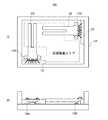
図19は、第8の実施の形態に係る角速度センサ900の分解斜視図である。この角速度センサ900は、角速度センサと加速度センサの両方を備えた構成である。以下、この角速度センサ900をセンサモジュールという。センサモジュール900は、1軸方向の角速度センサ910と3次元の角速度を検出できる加速度センサ920とを有する。モールドフレーム940は矩形状の底部942と、この底部から垂直方向に延びるセパレータ944とを有する。セパレータ944の両側にそれぞれ角速度センサ910と加速度センサ920とが設けられている。角速度センサ910は、樹脂などの固定部材950を用いてセパレータ944に固定されている。角速度センサ910は4本のアームとこれらを支持するベースとを持つ音叉型振動子912を有する。ベースは、空間上に配置されたリードフレームで、前述したように支持されている。加速度センサ920は、回路基板930の一方の面に取り付けられている。回路基板930はモールドフレーム940の底部942に垂直に取り付けられている。加速度センサ920とセパレータ944とは、連結部材946により連結されている。角速度センサ910と加速度センサ920とは、フレキシブル配線基板960を介して電気的に接続されている。角速度センサ910と加速度センサ920とは、キャップ970で封止される。
(Eighth embodiment)
FIG. 19 is an exploded perspective view of anangular velocity sensor 900 according to the eighth embodiment. Thisangular velocity sensor 900 is configured to include both an angular velocity sensor and an acceleration sensor. Hereinafter, thisangular velocity sensor 900 is referred to as a sensor module. Thesensor module 900 includes a uniaxialangular velocity sensor 910 and anacceleration sensor 920 that can detect a three-dimensional angular velocity. The mold frame 940 has arectangular bottom portion 942 and a separator 944 extending from the bottom portion in the vertical direction. Anangular velocity sensor 910 and anacceleration sensor 920 are provided on both sides of the separator 944, respectively. Theangular velocity sensor 910 is fixed to the separator 944 using a fixingmember 950 such as resin. Theangular velocity sensor 910 includes atuning fork vibrator 912 having four arms and a base that supports these arms. The base is a lead frame arranged in space and supported as described above. Theacceleration sensor 920 is attached to one surface of thecircuit board 930. Thecircuit board 930 is vertically attached to thebottom 942 of the mold frame 940. Theacceleration sensor 920 and the separator 944 are connected by a connectingmember 946. Theangular velocity sensor 910 and theacceleration sensor 920 are electrically connected via aflexible wiring board 960. Theangular velocity sensor 910 and theacceleration sensor 920 are sealed with acap 970.

このように構成された角速度センサ910をセパレータ944に取り付ける前後で発生する周波数変動は抑制され、高い精度かつ小型の角速度センサ及び加速度センサ920を備えたセンサモジュールを提供することができる。  Frequency fluctuations occurring before and after theangular velocity sensor 910 configured in this manner is attached to the separator 944 are suppressed, and a sensor module including a highly accurate and small angular velocity sensor andacceleration sensor 920 can be provided.

以上、本発明の実施の形態を説明した。本発明は上記実施の形態に限定されるものではなく、これらの実施の形態を変形した構成や他の実施の形態を含むものである。例えば、音叉型振動子は2本〜4本のアームを持つ構成であってよい。  The embodiment of the present invention has been described above. The present invention is not limited to the above-described embodiments, but includes configurations obtained by modifying these embodiments and other embodiments. For example, the tuning fork vibrator may have two to four arms.

本発明の第1の実施の形態を示す図である。It is a figure which shows the 1st Embodiment of this invention.本発明で用いられる空間の作用効果を、比較例と対比して説明するグラフである。It is a graph explaining the effect of the space used by this invention in contrast with a comparative example.ベースの自由長(非固定エリア)と周波数変化率との関係を示す図である。It is a figure which shows the relationship between the free length (non-fixed area) of a base, and a frequency change rate.音叉型振動子を示す図であり、アーム幅と自由長とを示す図である。It is a figure which shows a tuning fork type vibrator, and is a figure which shows arm width and free length.リードフレームの他の形態を示す図である。It is a figure which shows the other form of a lead frame.台形状およびM字状リードフレームの作用効果を説明するための図である。It is a figure for demonstrating the effect of a trapezoid shape and an M-shaped lead frame.音叉型振動子の電極パターンを示す図である。It is a figure which shows the electrode pattern of a tuning fork type vibrator.本発明の第1の実施の形態を示す図である。It is a figure which shows the 1st Embodiment of this invention.本発明の第2の実施の形態で用いられる回路基板を示す図である。It is a figure which shows the circuit board used by the 2nd Embodiment of this invention.本発明の第2の実施の形態を示す図である。It is a figure which shows the 2nd Embodiment of this invention.角速度センサ部品を回路基板に取り付ける様子を示す図である。It is a figure which shows a mode that an angular velocity sensor component is attached to a circuit board.本発明の第3の実施の形態を示す図である。It is a figure which shows the 3rd Embodiment of this invention.本発明の第3の実施の形態において、角速度センサ部品の傾斜配置を説明するための図である。In the 3rd Embodiment of this invention, it is a figure for demonstrating the inclination arrangement | positioning of angular velocity sensor components.本発明の第4の実施の形態を示す図である。It is a figure which shows the 4th Embodiment of this invention.本発明の第5の実施の形態を示す図である。It is a figure which shows the 5th Embodiment of this invention.本発明の第6実施の形態を示す図である。It is a figure which shows 6th Embodiment of this invention.第6の実施の形態を変形した構成を示す図である。It is a figure which shows the structure which deform | transformed 6th Embodiment.本発明の第7の実施の形態を示す図である。It is a figure which shows the 7th Embodiment of this invention.本発明の第8の実施の形態を示す図である。It is a figure which shows the 8th Embodiment of this invention.

符号の説明Explanation of symbols

10、10A、10B、 音叉型振動子
11、12 アーム
13 ベース
20 リードフレーム
21、24 平坦部
22 屈曲部
23 L字状折り返し部
30 パッケージ
31 空間
32 パッド
33 バンク
34、35 外部接続パッド
100、100A、100B、200、300、400、500、600、700、800、900 角速度センサ
10, 10A, 10B,tuning fork vibrator 11, 12arm 13base 20lead frame 21, 24flat portion 22 bent portion 23 L-shaped foldedportion 30package 31space 32pad 33bank 34, 35external connection pads 100, 100A , 100B, 200, 300, 400, 500, 600, 700, 800, 900 Angular velocity sensor

Claims (25)

Translated fromJapanese
ベースから延びる複数のアームを有する音叉型振動子と、前記ベースを支持する単一のリードフレームと、該リードフレームを支持するパッケージとを有し、該パッケージと前記リードフレームとの間に空間が形成されていることを特徴とする角速度センサ。  A tuning fork vibrator having a plurality of arms extending from a base, a single lead frame that supports the base, and a package that supports the lead frame, and there is a space between the package and the lead frame An angular velocity sensor characterized by being formed. 前記単一のリードフレームは、断面がコの字状の屈曲部を有し、該屈曲部は前記ベースを支持し、前記屈曲部が前記空間を形成することを特徴とする請求項1記載の角速度センサ。  The single lead frame has a bent portion having a U-shaped cross section, the bent portion supports the base, and the bent portion forms the space. Angular velocity sensor. 前記単一のリードフレームは、断面が台形状の屈曲部を有し、該屈曲部は前記ベースを支持し、前記屈曲部が前記空間を形成することを特徴とする請求項1記載の角速度センサ。  The angular velocity sensor according to claim 1, wherein the single lead frame has a bent portion having a trapezoidal cross section, the bent portion supports the base, and the bent portion forms the space. . 前記単一のリードフレームは、断面がM字状の屈曲部を有し、該屈曲部は前記ベースを支持し、前記屈曲部が前記空間を形成することを特徴とする請求項1記載の角速度センサ。  The angular velocity according to claim 1, wherein the single lead frame has a bent portion having an M-shaped cross section, the bent portion supports the base, and the bent portion forms the space. Sensor. 前記単一のリードフレームは、前記ベースを支持する平坦部を有し、前記平坦部がL字状の折り返しを有することを特徴とする請求項1から4のいずれか1項記載の角速度センサ。  5. The angular velocity sensor according to claim 1, wherein the single lead frame has a flat portion that supports the base, and the flat portion has an L-shaped turnback. 前記単一のリードフレームは、前記ベースを支持する平坦部を有し、前記リードフレームを支持する前記パッケージの面には凹部が形成されており、前記凹部が前記空間を形成することを特徴とする請求項1記載の角速度センサ。  The single lead frame has a flat portion that supports the base, and a recess is formed on a surface of the package that supports the lead frame, and the recess forms the space. The angular velocity sensor according to claim 1. 前記単一のリードフレームは、コの字状の平面形状を有することを特徴とする請求項1から6のいずれか1項記載の角速度センサ。  The angular velocity sensor according to claim 1, wherein the single lead frame has a U-shaped planar shape. 前記単一のリードフレームは、平板状であることを特徴とする請求項1から6のいずれか1項記載の角速度センサ。  The angular velocity sensor according to claim 1, wherein the single lead frame has a flat plate shape. 前記単一のリードフレームは、前記ベースとの接触部がすべて接着されていることを特徴とする請求項1から7のいずれか1項記載の角速度センサ。  The angular velocity sensor according to any one of claims 1 to 7, wherein the single lead frame is bonded to all the contact portions with the base. 前記単一のリードフレームは、バネ性を有することを特徴とする請求項1から8のいずれか1項記載の角速度センサ。    The angular velocity sensor according to claim 1, wherein the single lead frame has a spring property. 前記角速度センサは、前記パッケージを支持する回路基板と、前記角速度センサの実装面に対して前記回路基板を垂直に支持する支持基板とを有することを特徴とする請求項1から10のいずれか1項記載の角速度センサ。  The said angular velocity sensor has a circuit board which supports the said package, and a support substrate which supports the said circuit board perpendicularly with respect to the mounting surface of the said angular velocity sensor, The any one of Claim 1 to 10 characterized by the above-mentioned. The angular velocity sensor according to item. 前記角速度センサは、前記回路基板上に形成されたチップ部品を有し、前記パッケージは前記チップ部品を覆うように前記回路基板に取り付けられていることを特徴とする請求項11記載の角速度センサ。  The angular velocity sensor according to claim 11, wherein the angular velocity sensor has a chip component formed on the circuit board, and the package is attached to the circuit board so as to cover the chip component. 前記角速度センサは、前記パッケージを支持する支持基板と、前記パッケージに支持される接続部材と、該接続部材を介して前記パッケージとの電気的接続が形成される回路基板とを有することを特徴とする請求項1から10のいずれか1項記載の角速度センサ。  The angular velocity sensor includes a support substrate that supports the package, a connection member that is supported by the package, and a circuit substrate that is electrically connected to the package through the connection member. The angular velocity sensor according to any one of claims 1 to 10. 前記角速度センサは、前記回路基板上に形成されたチップ部品を有し、前記パッケージは前記チップ部品を覆うように、前記接続部材を介して前記回路基板を支持することを特徴とする請求項13記載の角速度センサ。  14. The angular velocity sensor includes a chip component formed on the circuit board, and the package supports the circuit board via the connection member so as to cover the chip component. The angular velocity sensor described. 前記角速度センサは、前記パッケージを支持する支持基板と、該支持基板に支持された加速度センサとを有することを特徴とする請求項1から10のいずれか1項記載の角速度センサ。  11. The angular velocity sensor according to claim 1, wherein the angular velocity sensor includes a support substrate that supports the package and an acceleration sensor that is supported by the support substrate. 前記角速度センサは、前記支持基板に取り付けられた回路基板を有し、前記加速度センサは該回路基板に取り付けられ、該回路基板と前記パッケージとはフレキシブル配線基板により電気的に接続されていることを特徴とする請求項15記載の角速度センサ。  The angular velocity sensor has a circuit board attached to the support board, the acceleration sensor is attached to the circuit board, and the circuit board and the package are electrically connected by a flexible wiring board. The angular velocity sensor according to claim 15, wherein 前記角速度センサは、前記パッケージと前記加速度センサとを封止するキャップを有することを特徴とする請求項15又は16記載の角速度センサ。  The angular velocity sensor according to claim 15 or 16, wherein the angular velocity sensor has a cap that seals the package and the acceleration sensor. ベースから延びる複数のアームを有する音叉型振動子と、前記ベースを支持する単一のリードフレームとを有するユニットを複数個有し、該複数個のユニットを収容するパッケージを有し、前記複数個のユニットの角速度検出軸が異なる方向となるように前記パッケージ内に前記複数個のユニットを配置したことを特徴とする角速度センサ。  A plurality of units having a tuning fork type vibrator having a plurality of arms extending from the base and a single lead frame supporting the base; a package for housing the plurality of units; An angular velocity sensor, wherein the plurality of units are arranged in the package so that the angular velocity detection axes of the units are in different directions. 前記複数個のユニットは、前記パッケージの面から同一の高さ位置に配置されていることを特徴とする請求項18記載の角速度センサ。  The angular velocity sensor according to claim 18, wherein the plurality of units are arranged at the same height from the surface of the package. 前記複数個のユニットは、前記パッケージの面から異なる高さ位置に配置されていることを特徴とする請求項18記載の角速度センサ。  The angular velocity sensor according to claim 18, wherein the plurality of units are arranged at different height positions from the surface of the package. 前記複数個のユニットは、音叉型振動子のアームの延在方向が交差するように配置されていることを特徴とする請求項18記載の角速度センサ。  The angular velocity sensor according to claim 18, wherein the plurality of units are arranged so that extending directions of arms of a tuning fork vibrator intersect. 複数個の角速度センサ部品と、該角速度センサ部品が取り付けられる回路基板とを有し、前記角速度センサ部品の各々は、ベースから延びる複数のアームを有する音叉型振動子と、前記ベースを支持する単一のリードフレームと、該リードフレームを支持するパッケージとを有し、該パッケージと前記リードフレームとの間に空間が形成されていることを特徴とする角速度センサ。  A plurality of angular velocity sensor components; and a circuit board to which the angular velocity sensor components are attached. Each of the angular velocity sensor components includes a tuning fork vibrator having a plurality of arms extending from a base, and a single unit that supports the base. An angular velocity sensor comprising a lead frame and a package for supporting the lead frame, and a space is formed between the package and the lead frame. 前記各角速度センサ部品のパッケージは開口面を有し、前記回路基板は前記開口面を塞ぐように前記角速度センサ部品を支持することを特徴とする請求項22記載の角速度センサ。  23. The angular velocity sensor according to claim 22, wherein the package of each angular velocity sensor component has an opening surface, and the circuit board supports the angular velocity sensor component so as to close the opening surface. 前記回路基板に電子部品が設けられ、前記各角速度センサ部品のパッケージは、前記電子部品を覆うように前記回路基板に取り付けられていることを特徴とする請求項23記載の角速度センサ。  24. The angular velocity sensor according to claim 23, wherein an electronic component is provided on the circuit board, and a package of each angular velocity sensor component is attached to the circuit board so as to cover the electronic component. 前記各角速度センサ部品のパッケージの取り付け面は第1の端子を有し、前記回路基板は前記第1の端子と接続される第2の端子を有し、第2の端子の配置が前記角速度センサ部品の角速度検出軸を決定していることを特徴とする請求項22から24のいずれか一項記載の角速度センサ。
The mounting surface of the package of each angular velocity sensor component has a first terminal, the circuit board has a second terminal connected to the first terminal, and the arrangement of the second terminal is the angular velocity sensor. The angular velocity sensor according to any one of claims 22 to 24, wherein an angular velocity detection axis of the part is determined.
JP2005239711A2005-03-312005-08-22 Angular velocity sensorPendingJP2006308543A (en)

Priority Applications (7)

Application NumberPriority DateFiling DateTitle
JP2005239711AJP2006308543A (en)2005-03-312005-08-22 Angular velocity sensor
EP06251597AEP1707920A2 (en)2005-03-312006-03-24Angular velocity sensor
KR1020060028701AKR20060105534A (en)2005-03-312006-03-30 Angular velocity sensor
US11/392,930US20060219008A1 (en)2005-03-312006-03-30Angular velocity sensor
CN2006100733347ACN1841020B (en)2005-03-312006-03-31Angular velocity sensor
US11/979,486US20080066547A1 (en)2005-03-312007-11-05Angular velocity sensor
KR1020080010004AKR20080015500A (en)2005-03-312008-01-31 Angular velocity sensor

Applications Claiming Priority (2)

Application NumberPriority DateFiling DateTitle
JP20051044412005-03-31
JP2005239711AJP2006308543A (en)2005-03-312005-08-22 Angular velocity sensor

Publications (1)

Publication NumberPublication Date
JP2006308543Atrue JP2006308543A (en)2006-11-09

Family

ID=36607350

Family Applications (1)

Application NumberTitlePriority DateFiling Date
JP2005239711APendingJP2006308543A (en)2005-03-312005-08-22 Angular velocity sensor

Country Status (5)

CountryLink
US (2)US20060219008A1 (en)
EP (1)EP1707920A2 (en)
JP (1)JP2006308543A (en)
KR (2)KR20060105534A (en)
CN (1)CN1841020B (en)

Cited By (6)

* Cited by examiner, † Cited by third party
Publication numberPriority datePublication dateAssigneeTitle
JP2007248187A (en)*2006-03-152007-09-27Matsushita Electric Ind Co Ltd Angular velocity sensor
JP2007285978A (en)*2006-04-192007-11-01Fujitsu Media Device Kk Angular velocity sensor
EP1950529A1 (en)2007-01-232008-07-30Fujitsu Ltd.Angular velocity sensor
WO2010026818A1 (en)*2008-09-022010-03-11株式会社村田製作所Angular speed sensor
JP2012522382A (en)*2009-03-262012-09-20ケメット エレクトロニクス コーポレーション Leaded multilayer ceramic capacitor with low ESL and ESR
JP2014048090A (en)*2012-08-302014-03-17Seiko Epson CorpElectronic module, electronic apparatus, and movable body

Families Citing this family (34)

* Cited by examiner, † Cited by third party
Publication numberPriority datePublication dateAssigneeTitle
JP2007292470A (en)*2006-04-202007-11-08Fujitsu Media Device Kk Angular velocity sensor
US7816698B2 (en)*2007-04-132010-10-19Industrial Technology Research InstituteHeat dissipation package for heat generation element
US8462109B2 (en)*2007-01-052013-06-11Invensense, Inc.Controlling and accessing content using motion processing on mobile devices
US7934423B2 (en)2007-12-102011-05-03Invensense, Inc.Vertically integrated 3-axis MEMS angular accelerometer with integrated electronics
US8952832B2 (en)2008-01-182015-02-10Invensense, Inc.Interfacing application programs and motion sensors of a device
US8250921B2 (en)2007-07-062012-08-28Invensense, Inc.Integrated motion processing unit (MPU) with MEMS inertial sensing and embedded digital electronics
CN101657081A (en)*2008-08-202010-02-24鸿富锦精密工业(深圳)有限公司Electronic device
DE102009001247A1 (en)*2009-02-272010-09-09Sensordynamics Ag Micro-electro-mechanical sensor
US8797279B2 (en)2010-05-252014-08-05MCube Inc.Analog touchscreen methods and apparatus
US8928602B1 (en)2009-03-032015-01-06MCube Inc.Methods and apparatus for object tracking on a hand-held device
US8823007B2 (en)2009-10-282014-09-02MCube Inc.Integrated system on chip using multiple MEMS and CMOS devices
US8553389B1 (en)2010-08-192013-10-08MCube Inc.Anchor design and method for MEMS transducer apparatuses
US8421082B1 (en)2010-01-192013-04-16Mcube, Inc.Integrated CMOS and MEMS with air dielectric method and system
US8477473B1 (en)2010-08-192013-07-02MCube Inc.Transducer structure and method for MEMS devices
US8710597B1 (en)2010-04-212014-04-29MCube Inc.Method and structure for adding mass with stress isolation to MEMS structures
US8476129B1 (en)2010-05-242013-07-02MCube Inc.Method and structure of sensors and MEMS devices using vertical mounting with interconnections
US9709509B1 (en)2009-11-132017-07-18MCube Inc.System configured for integrated communication, MEMS, Processor, and applications using a foundry compatible semiconductor process
US8637943B1 (en)2010-01-042014-01-28MCube Inc.Multi-axis integrated MEMS devices with CMOS circuits and method therefor
US8584521B1 (en)*2010-01-192013-11-19MCube Inc.Accurate gyroscope device using MEMS and quartz
US8936959B1 (en)2010-02-272015-01-20MCube Inc.Integrated rf MEMS, control systems and methods
US8794065B1 (en)*2010-02-272014-08-05MCube Inc.Integrated inertial sensing apparatus using MEMS and quartz configured on crystallographic planes
US8367522B1 (en)2010-04-082013-02-05MCube Inc.Method and structure of integrated micro electro-mechanical systems and electronic devices using edge bond pads
US8928696B1 (en)2010-05-252015-01-06MCube Inc.Methods and apparatus for operating hysteresis on a hand held device
US8652961B1 (en)2010-06-182014-02-18MCube Inc.Methods and structure for adapting MEMS structures to form electrical interconnections for integrated circuits
US8869616B1 (en)2010-06-182014-10-28MCube Inc.Method and structure of an inertial sensor using tilt conversion
US8993362B1 (en)2010-07-232015-03-31MCube Inc.Oxide retainer method for MEMS devices
US8723986B1 (en)2010-11-042014-05-13MCube Inc.Methods and apparatus for initiating image capture on a hand-held device
KR101239636B1 (en)*2011-04-082013-03-11국방과학연구소Mems resonator, sensor having the same and manufacturing method for mems resonator
US8969101B1 (en)2011-08-172015-03-03MCube Inc.Three axis magnetic sensor device and method using flex cables
US9581445B2 (en)*2012-06-042017-02-28Systron Donner Inertial, Inc.Torsional rate measuring gyroscope
JP6256145B2 (en)*2014-03-262018-01-10株式会社デンソー Semiconductor device and manufacturing method thereof
JP6432190B2 (en)*2014-07-252018-12-05セイコーエプソン株式会社 Vibration element, method for manufacturing vibration element, vibrator, electronic device, and moving body
JP6464749B2 (en)*2015-01-062019-02-06セイコーエプソン株式会社 Physical quantity sensor, electronic device and mobile object
CN118140119A (en)*2021-09-142024-06-04苹果公司Sensor assembly

Citations (3)

* Cited by examiner, † Cited by third party
Publication numberPriority datePublication dateAssigneeTitle
JPH08114458A (en)*1994-10-131996-05-07Nippondenso Co LtdAngular velocity sensor
JPH10197254A (en)*1997-01-071998-07-31Alps Electric Co LtdSupporting device for vibrator
JP2005003538A (en)*2003-06-122005-01-06Fujitsu Ltd Support structure for vibrating gyroscope

Family Cites Families (5)

* Cited by examiner, † Cited by third party
Publication numberPriority datePublication dateAssigneeTitle
US5698784A (en)*1996-01-241997-12-16Gyration, Inc.Vibratory rate gyroscope and methods of assembly and operation
US6182508B1 (en)*1996-12-182001-02-06Denso CorporationStructure of angular rate sensor
US6578420B1 (en)*1997-01-282003-06-17Microsensors, Inc.Multi-axis micro gyro structure
JP3966237B2 (en)*2003-06-192007-08-29セイコーエプソン株式会社 Piezoelectric devices and electronic devices equipped with piezoelectric devices
US7196404B2 (en)*2004-05-202007-03-27Analog Devices, Inc.Motion detector and method of producing the same

Patent Citations (3)

* Cited by examiner, † Cited by third party
Publication numberPriority datePublication dateAssigneeTitle
JPH08114458A (en)*1994-10-131996-05-07Nippondenso Co LtdAngular velocity sensor
JPH10197254A (en)*1997-01-071998-07-31Alps Electric Co LtdSupporting device for vibrator
JP2005003538A (en)*2003-06-122005-01-06Fujitsu Ltd Support structure for vibrating gyroscope

Cited By (6)

* Cited by examiner, † Cited by third party
Publication numberPriority datePublication dateAssigneeTitle
JP2007248187A (en)*2006-03-152007-09-27Matsushita Electric Ind Co Ltd Angular velocity sensor
JP2007285978A (en)*2006-04-192007-11-01Fujitsu Media Device Kk Angular velocity sensor
EP1950529A1 (en)2007-01-232008-07-30Fujitsu Ltd.Angular velocity sensor
WO2010026818A1 (en)*2008-09-022010-03-11株式会社村田製作所Angular speed sensor
JP2012522382A (en)*2009-03-262012-09-20ケメット エレクトロニクス コーポレーション Leaded multilayer ceramic capacitor with low ESL and ESR
JP2014048090A (en)*2012-08-302014-03-17Seiko Epson CorpElectronic module, electronic apparatus, and movable body

Also Published As

Publication numberPublication date
KR20060105534A (en)2006-10-11
US20060219008A1 (en)2006-10-05
US20080066547A1 (en)2008-03-20
CN1841020A (en)2006-10-04
KR20080015500A (en)2008-02-19
EP1707920A2 (en)2006-10-04
CN1841020B (en)2010-04-14

Similar Documents

PublicationPublication DateTitle
JP2006308543A (en) Angular velocity sensor
KR100779352B1 (en)Angular velocity sensor
JP4084354B2 (en) Angular velocity sensor
CN102915980A (en)Substrate, electronic device, and electronic apparatus
KR20060089633A (en) Piezoelectric Devices and Electronics
US9123883B2 (en)Vibration device
CN116358510A (en) sensor module
CN116953283A (en)Inertial sensor and inertial measurement device
CN113257746B (en) Vibration device
JP2006229121A (en) Piezoelectric device, piezoelectric device, and electronic apparatus
EP1760429A2 (en)Angular velocity sensor
US20250155466A1 (en)Method For Manufacturing Electronic Device
US11906538B2 (en)Sensor module
US12438292B2 (en)Electronic device
CN112272754A (en) Sensor element and angular velocity sensor
US20250172393A1 (en)Vibrator Device And Method For Manufacturing Vibrator Device
US20250311108A1 (en)Sensor Module
CN119545697A (en) Sensor element and physical quantity sensor
JP2023105388A (en) sensor module
JP2009048827A (en) Sensor socket and sensor module
JP2024069866A (en) Electronic Components and Sensor Modules
JP2022054045A (en)Inertial measurement device
JP2024034074A (en) inertial detection device
JP2008261636A (en) Acceleration sensor

Legal Events

DateCodeTitleDescription
A621Written request for application examination

Free format text:JAPANESE INTERMEDIATE CODE: A621

Effective date:20070620

A711Notification of change in applicant

Free format text:JAPANESE INTERMEDIATE CODE: A711

Effective date:20090423

A521Written amendment

Free format text:JAPANESE INTERMEDIATE CODE: A523

Effective date:20090424

A977Report on retrieval

Free format text:JAPANESE INTERMEDIATE CODE: A971007

Effective date:20100108

A131Notification of reasons for refusal

Free format text:JAPANESE INTERMEDIATE CODE: A131

Effective date:20100420

A521Written amendment

Free format text:JAPANESE INTERMEDIATE CODE: A523

Effective date:20100607

A02Decision of refusal

Free format text:JAPANESE INTERMEDIATE CODE: A02

Effective date:20100720


[8]ページ先頭

©2009-2025 Movatter.jp