JP2006308375A - Infrared eye position detector - Google Patents
Infrared eye position detectorDownload PDFInfo
- Publication number
- JP2006308375A JP2006308375AJP2005129842AJP2005129842AJP2006308375AJP 2006308375 AJP2006308375 AJP 2006308375AJP 2005129842 AJP2005129842 AJP 2005129842AJP 2005129842 AJP2005129842 AJP 2005129842AJP 2006308375 AJP2006308375 AJP 2006308375A
- Authority
- JP
- Japan
- Prior art keywords
- face
- eye position
- face image
- authentication
- infrared
- Prior art date
- Legal status (The legal status is an assumption and is not a legal conclusion. Google has not performed a legal analysis and makes no representation as to the accuracy of the status listed.)
- Pending
Links
Images


Landscapes
- Lock And Its Accessories (AREA)
- Length Measuring Devices By Optical Means (AREA)
- Collating Specific Patterns (AREA)
Abstract
Translated fromJapaneseDescription
Translated fromJapanese本発明は、赤外線を利用して目の位置を検出する赤外線利用型目位置検出装置に関するものである。 The present invention relates to an infrared type eye position detection device that detects the position of an eye using infrared rays.
従来の赤外線利用型目位置検出装置としては、取得画像の温度分布に基づいて目の位置を検出するものが知られている(例えば、特許文献1参照。)。 As a conventional infrared eye type eye position detection device, one that detects the eye position based on the temperature distribution of an acquired image is known (for example, see Patent Document 1).
しかしながら、従来の赤外線利用型目位置検出装置においては、取得画像の温度分布に基づいて目の位置を検出するので、画像のコントラストが十分に取れず、目の位置の検出の精度が低いという問題があった。 However, in the conventional infrared eye type eye position detection device, the eye position is detected based on the temperature distribution of the acquired image, so that the contrast of the image cannot be sufficiently obtained, and the accuracy of the eye position detection is low. was there.
本発明は、従来の問題を解決するためになされたもので、目の位置を従来より高精度に検出することができる赤外線利用型目位置検出装置を提供することを目的とする。 The present invention has been made to solve the conventional problems, and an object of the present invention is to provide an infrared utilizing eye position detection device capable of detecting the position of the eyes with higher accuracy than in the past.
本発明の赤外線利用型目位置検出装置は、赤外線を照射する赤外線照射手段と、前記赤外線照射手段によって照射された前記赤外線の反射光を捉える赤外線撮像手段と、前記赤外線撮像手段によって撮像された画像から顔の画像を取得する顔画像取得手段と、前記顔画像取得手段によって取得された前記顔の画像中の輝度に基づいて前記顔の画像中の目の位置を検出する目位置検出手段とを備えた構成を有している。 An infrared-based eye position detection device according to the present invention includes an infrared irradiation unit that irradiates infrared rays, an infrared imaging unit that captures reflected light of the infrared rays irradiated by the infrared irradiation unit, and an image captured by the infrared imaging unit. A face image acquisition means for acquiring a face image from the eye, and an eye position detection means for detecting the position of the eye in the face image based on the luminance in the face image acquired by the face image acquisition means. It has the composition provided.
この構成により、本発明の赤外線利用型目位置検出装置は、自身が照射した赤外線の反射光に基づいて目の位置を検出するので、顔の画像における目の画像が従来より明確になり、目の位置を従来より高精度に検出することができる。 With this configuration, the infrared-based eye position detection device of the present invention detects the position of the eye based on the reflected infrared light irradiated by itself, so that the eye image in the face image becomes clearer than before, Can be detected with higher accuracy than in the past.
また、本発明の赤外線利用型目位置検出装置は、顔認証を行う顔認証手段と、前記顔認証用の顔の画像を記憶する顔画像記憶手段とを備え、前記顔認証手段は、前記顔画像取得手段によって取得され前記目位置検出手段によって前記目の位置が検出された前記顔の画像と、前記顔画像記憶手段によって記憶された前記顔の画像とに基づいて、前記顔認証を行う構成を有している。 The eye position detection device using infrared rays of the present invention includes face authentication means for performing face authentication and face image storage means for storing the face image for face authentication, wherein the face authentication means includes the face authentication means. Configuration for performing the face authentication based on the face image acquired by the image acquisition unit and the eye position detection unit detecting the eye position, and the face image stored by the face image storage unit have.
この構成により、本発明の赤外線利用型目位置検出装置は、目の位置を従来より高精度に検出することができるので、従来より高精度に顔認証を行うことができる。 With this configuration, the infrared-based eye position detection device of the present invention can detect the position of the eyes with higher accuracy than before, and can perform face authentication with higher accuracy than before.
また、本発明の赤外線利用型目位置検出装置は、前記顔画像取得手段によって取得された前記顔の画像における前記顔の向きを前記目位置検出手段によって検出された前記目の位置に基づいて推定する顔向推定手段と、前記顔画像記憶手段によって記憶された複数の前記顔の画像から少なくとも1つの前記顔の画像を前記顔向推定手段によって推定された前記顔の向きに基づいて選択する顔画像選択手段とを備え、前記顔認証手段は、前記顔画像取得手段によって取得され前記目位置検出手段によって前記目の位置が検出された前記顔の画像と、前記顔画像選択手段によって選択された前記顔の画像とに基づいて、前記顔認証を行う構成を有している。 In addition, the infrared eye type eye position detection apparatus according to the present invention estimates the orientation of the face in the face image acquired by the face image acquisition means based on the eye position detected by the eye position detection means. A face direction estimating unit that selects at least one face image from the plurality of face images stored by the face image storing unit based on the face direction estimated by the face direction estimating unit An image selecting means, wherein the face authenticating means is selected by the face image selecting means acquired by the face image acquiring means, and the face image from which the eye position is detected by the eye position detecting means. The face authentication is performed based on the face image.
この構成により、本発明の赤外線利用型目位置検出装置は、予め記憶している顔の画像のうち実際の顔の向きに近い向きの顔の画像に基づいて顔認証を行うことができるので、より確実に顔認証を行うことができる。 With this configuration, the infrared-based eye position detection device of the present invention can perform face authentication based on a face image in a direction close to the actual face direction among pre-stored face images. Face authentication can be performed more reliably.
また、本発明の赤外線利用型目位置検出装置は、前記顔画像取得手段によって取得された前記顔の画像における前記顔の向きを確定する顔向確定手段を備え、前記顔画像選択手段は、前記顔画像記憶手段によって記憶された複数の前記顔の画像から2つ以上の前記顔の画像を前記顔向推定手段によって推定された前記顔の向きに基づいて選択し、前記顔向確定手段は、前記顔画像選択手段によって選択された前記顔の画像毎の前記顔認証手段による前記顔認証の結果に基づいて、前記顔画像取得手段によって取得された前記顔の画像における前記顔の向きを確定する構成を有している。 In addition, the infrared-based eye position detection device of the present invention includes a face orientation determination unit that determines the orientation of the face in the face image acquired by the face image acquisition unit, and the face image selection unit includes the face image selection unit, Two or more facial images are selected from the plurality of facial images stored by the facial image storage means based on the facial orientation estimated by the facial orientation estimation means, and the facial orientation determination means comprises: Based on the result of the face authentication by the face authentication unit for each face image selected by the face image selection unit, the orientation of the face in the face image acquired by the face image acquisition unit is determined. It has a configuration.
この構成により、本発明の赤外線利用型目位置検出装置は、複数の顔認証の結果に基づいて顔認証の対象者の顔の向きを確定するので、赤外線撮像手段によって撮像された対象者の顔の向きを高精度に確定することができる。 With this configuration, the infrared-based eye position detection device of the present invention determines the orientation of the face of the face authentication target person based on a plurality of face authentication results, so the face of the target person imaged by the infrared imaging means Can be determined with high accuracy.
また、本発明の赤外線利用型目位置検出装置は、前記顔向確定手段によって確定された前記顔の向きに基づいて脇見運転を判定する脇見運転判定手段を備えた構成を有している。 Further, the infrared eye type eye position detection device of the present invention has a configuration including a side-by-side operation determination unit that determines a side-by-side operation based on the face orientation determined by the face direction determination unit.
この構成により、本発明の赤外線利用型目位置検出装置は、顔認証の対象者が乗物の運転者であるときに、運転者が脇見運転を行っているか否かを判定することができる。 With this configuration, the infrared-based eye position detection device according to the present invention can determine whether or not the driver is performing a side-by-side driving when the subject of face authentication is a vehicle driver.
また、本発明の赤外線利用型目位置検出装置は、虹彩認証を行う虹彩認証手段と、前記虹彩認証用の虹彩の画像を記憶する虹彩画像記憶手段とを備え、前記虹彩認証手段は、前記顔画像取得手段によって取得され前記目位置検出手段によって前記目の位置が検出された前記顔の画像中の前記目の虹彩の画像と、前記虹彩画像記憶手段に記憶された前記虹彩の画像とに基づいて、前記虹彩認証を行う構成を有している。 The eye position detection device using infrared rays of the present invention includes iris authentication means for performing iris authentication, and iris image storage means for storing an iris image for iris authentication, wherein the iris authentication means includes the face Based on the iris image stored in the iris image storage unit and the iris image stored in the iris image storage unit obtained by the image acquisition unit and the eye position detection unit detecting the eye position. The iris authentication is performed.
この構成により、本発明の赤外線利用型目位置検出装置は、目の位置を従来より高精度に検出することができるので、従来より高精度に虹彩認証を行うことができる。 With this configuration, the infrared-based eye position detection device of the present invention can detect the eye position with higher accuracy than in the past, and therefore can perform iris authentication with higher accuracy than in the past.
また、本発明の赤外線利用型目位置検出装置は、網膜認証を行う網膜認証手段と、前記網膜認証用の網膜の画像を記憶する網膜画像記憶手段とを備え、前記網膜認証手段は、前記顔画像取得手段によって取得され前記目位置検出手段によって前記目の位置が検出された前記顔の画像中の前記目の網膜の画像と、前記網膜画像記憶手段に記憶された前記網膜の画像とに基づいて、前記網膜認証を行う構成を有している。 The eye position detection device using infrared rays of the present invention includes retinal authentication means for performing retinal authentication, and retinal image storage means for storing an image of the retina for retinal authentication, wherein the retinal authentication means includes the face Based on the retina image of the eye in the face image acquired by the image acquisition means and the eye position detected by the eye position detection means, and the retina image stored in the retinal image storage means Thus, the retina authentication is performed.
この構成により、本発明の赤外線利用型目位置検出装置は、目の位置を従来より高精度に検出することができるので、従来より高精度に網膜認証を行うことができる。 With this configuration, the infrared-based eye position detection device of the present invention can detect the position of the eyes with higher accuracy than before, and therefore can perform retina authentication with higher accuracy than before.
また、本発明の赤外線利用型目位置検出装置は、前記顔画像取得手段によって取得された前記顔の画像のコントラストに基づいて前記赤外線照射手段による前記赤外線の照射量を調整する赤外線照射量調整手段を備えた構成を有している。 In addition, the infrared-based eye position detection device of the present invention is an infrared irradiation amount adjustment unit that adjusts the amount of infrared irradiation by the infrared irradiation unit based on the contrast of the face image acquired by the face image acquisition unit. It has the composition provided with.
この構成により、本発明の赤外線利用型目位置検出装置は、赤外線の照射量を調整するので、より高精度に目の位置を検出することができる。 With this configuration, the infrared-based eye position detection device of the present invention adjusts the amount of infrared irradiation, so that the eye position can be detected with higher accuracy.
また、本発明の赤外線利用型目位置検出装置は、前記赤外線撮像手段の撮像環境の明暗を検出する明暗検出手段と、前記明暗検出手段による検出結果に基づいて前記赤外線照射手段による前記赤外線の照射量を調整する赤外線照射量調整手段とを備えた構成を有している。 In addition, the infrared-based eye position detection device according to the present invention includes a light / dark detection unit that detects light and darkness of an imaging environment of the infrared imaging unit, and the infrared irradiation by the infrared irradiation unit based on a detection result by the light / dark detection unit. And an infrared irradiation amount adjusting means for adjusting the amount.
この構成により、本発明の赤外線利用型目位置検出装置は、赤外線の照射量を調整するので、より高精度に目の位置を検出することができる。 With this configuration, the infrared-based eye position detection device of the present invention adjusts the amount of infrared irradiation, so that the eye position can be detected with higher accuracy.
本発明は、画像処理の負荷を軽減しながら目の位置を従来より高精度に検出することができる赤外線利用型目位置検出装置を提供することができるものである。 The present invention can provide an infrared-based eye position detection device that can detect the eye position with higher accuracy than before while reducing the load of image processing.
以下、本発明の実施の形態について、図面を用いて説明する。 Hereinafter, embodiments of the present invention will be described with reference to the drawings.
(第1の実施の形態)
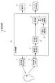
まず、本発明の第1の実施の形態に係る赤外線利用型目位置検出装置の構成について図1を用いて説明する。(First embodiment)
First, the configuration of the infrared-based eye position detection device according to the first embodiment of the present invention will be described with reference to FIG.
図1に示すように、本実施の形態に係る赤外線利用型目位置検出装置としての目位置検出装置10は、赤外線を照射する赤外線照射手段としての赤外線照射装置11と、赤外線照射装置11によって照射された赤外線の反射光を捉える赤外線撮像手段としての赤外線カメラ12と、赤外線照射装置11及び赤外線カメラ12の動作を制御する制御装置20と、目位置検出結果を報知する報知部14とを備えている。 As shown in FIG. 1, an eye position detection device 10 as an infrared-based eye position detection device according to the present embodiment is irradiated by an
制御装置20は、顔を赤外線カメラ12によって撮像し、その撮像された顔の画像(以下「顔画像」という。)を取得する顔画像取得手段としての顔画像取得部21と、顔画像取得部21によって取得された顔画像中の輝度に基づいて顔画像中の目の位置を検出する目位置検出手段としての目位置検出部22とを有している。なお、制御装置20は、例えば、CPU(Central Processing Unit)、ROM(Read Only Memory)及びRAM(Random Access Memory)等によって構成された一般的なコンピュータである。 The
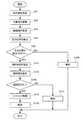
次に、目位置検出装置10の動作について、図2を用いて説明する。 Next, the operation of the eye position detection device 10 will be described with reference to FIG.
まず制御装置20は、対象者に向けて赤外線照射装置11に赤外線を照射させ(S41)、赤外線カメラ12に対象者を撮像させる(S42)。ここで、対象者の眼球の角膜や、角膜の前面の液体は、赤外線照射装置11によって照射された赤外線を対象者の顔の構成の中で最も多量に反射する。したがって、赤外線カメラ12によって撮像された画像中の顔画像においては、対象者の眼球の角膜や、角膜の前面の液体に対応する部分が撮像画像中、最も輝度が高くなる。 First, the
そして、制御装置20は、赤外線カメラ12によって撮像された画像から顔画像を顔画像取得部21によって取得して(S43)、顔画像取得部21によって取得された顔画像中の輝度に基づいて顔画像中の目の位置を目位置検出部22によって検出する(S44)。即ち、目位置検出部22は、顔画像取得部21によって取得された顔画像にイコライズ処理を行い、イコライズ処理を行った顔画像中の最も輝度が高い2点について2点の間隔や2点を通る直線と水平線との角度(図3参照。)が規定範囲内であるかを検証し、規定範囲内であると検証したとき、顔画像中の最も輝度が高い2点の位置を、目の位置として検出する。 Then, the
次いで、制御装置20は、目位置検出部22によって目の位置が検出できたか否かを判別し(S45)、目位置検出部22によって目の位置が検出できなかったとS45において判断すると、目の位置が検出できなかったことを報知部14によって利用者に報知する(S46)。例えば、運転者の両目の目位置が一定時間検出できないと、片目又は両目を開けていないか、又は横を向いていると判断し、『居眠り注意』等の注意音声を出力する。 Next, the
以上に説明したように、目位置検出装置10は、自身が照射した赤外線の反射光に基づいて目の位置を検出するので、顔画像における目の画像が従来より明確になり、目の位置を従来より高精度に検出することができる。また、目位置検出装置10は、顔画像における目の画像が従来より明確になるので、目の位置を検出するときの画像処理負荷を簡易にすることができる。また、目位置検出装置10は、可視光ではなく赤外線を利用して目の位置を検出するようになっているので、夜間であっても目の位置を高精度に検出することができる。 As described above, the eye position detection device 10 detects the position of the eye based on the reflected infrared light emitted by the eye, so the eye image in the face image becomes clearer than before, and the eye position is determined. It can be detected with higher accuracy than before. Further, the eye position detection device 10 can simplify the image processing load when detecting the eye position since the eye image in the face image becomes clearer than before. Moreover, since the eye position detection apparatus 10 detects an eye position using infrared rays instead of visible light, the eye position can be detected with high accuracy even at night.
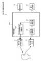
(第2の実施の形態)
まず、本発明の第2の実施の形態に係る赤外線利用型目位置検出装置の構成について図4を用いて説明する。(Second Embodiment)
First, the configuration of an infrared-based eye position detection device according to a second embodiment of the present invention will be described with reference to FIG.
なお、本実施の形態に係る赤外線利用型目位置検出装置の構成のうち、第1の実施の形態に係る目位置検出装置10(図1参照。)の構成と同様な構成については、目位置検出装置10の構成と同一の符号を付して説明する。 Of the configurations of the infrared-based eye position detection device according to the present embodiment, the same configuration as the configuration of the eye position detection device 10 (see FIG. 1) according to the first embodiment will be described. The description will be made with the same reference numerals as those of the detection device 10.
図4に示すように、本実施の形態に係る赤外線利用型目位置検出装置としての認証装置60の構成は、制御装置70を制御装置20(図1参照。)に代えて備えた目位置検出装置10が、エンジン始動制御を行うエンジン始動装置15を更に備えた構成と同様である。 As shown in FIG. 4, the configuration of the authentication device 60 serving as an infrared-based eye position detection device according to the present embodiment includes eye position detection in which a
また、制御装置70の構成は、顔認証を行う顔認証手段としての認証部71と、顔認証用の顔画像を記憶する顔画像記憶手段としての画像記憶部72と、画像記憶部72への顔画像の登録や画像記憶部72からの顔画像の削除を行う登録削除部73とを制御装置20が備えた構成と同様である。 The configuration of the
なお、認証部71は、顔画像取得部21によって取得され目位置検出部22によって目の位置が検出された顔画像と、画像記憶部72に記憶されている顔画像とに基づいて、顔認証を行うようになっている。 The
次に、認証装置60の動作について図5を用いて説明する。 Next, operation | movement of the authentication apparatus 60 is demonstrated using FIG.
なお、認証装置60の動作のうち、目位置検出装置10の動作と同様な動作については、目位置検出装置10の動作と同一の符号を付して説明を省略する。 Of the operations of the authentication device 60, the same operations as those of the eye position detection device 10 are denoted by the same reference numerals as those of the eye position detection device 10, and description thereof is omitted.
図5に示すように、制御装置70は、目位置検出部22によって目の位置が検出できたとS45において判断すると、顔画像取得部21によって取得され目位置検出部22によって目の位置が検出された顔画像と、画像記憶部72に記憶された顔画像とに基づいて、目位置を中心に正規化し認証部71によって顔認証を行う(S91)。認証がOKになると、制御装置70は、エンジン始動装置15に、エンジン始動要求を出力し、エンジン始動をし(S92)、認証結果がOKであったこととエンジン始動を開始したことを報知部14を通して運転者に報知する(S93)。 As shown in FIG. 5, when the
一方、S45において目位置検出ができなかった場合は、目位置検出ができなかった事を報知部14を通して運転者に報知し(S94)、目位置が検出できる様、正面に向くことを促す。 On the other hand, if the eye position cannot be detected in S45, the driver is notified through the
一方、S91で、顔認証NGの場合は、顔認証NGであった事とエンジン始動ができなかった事を報知部14を通して運転者に報知し(S95)、顔認証開始が認証開始SW押下による物であれば、それを押下する等、再度顔認証を開始する様、促す。 On the other hand, in the case of face authentication NG in S91, the driver is notified through the
以上に説明したように、認証装置60は、目位置検出装置10と同様に目の位置を従来より高精度に検出することができるので、画像処理の負荷を増すことなく従来より高精度に顔認証を行うことができる。 As described above, since the authentication device 60 can detect the position of the eyes with higher accuracy than in the past, as with the eye position detection device 10, the face with higher accuracy than in the past without increasing the load of image processing. Authentication can be performed.
なお、認証装置60は、顔認証を行うようになっているが、虹彩認証用の虹彩の画像を記憶する虹彩画像記憶手段として画像記憶部72を機能させ、顔画像取得部21によって取得され目位置検出部22によって目の位置が検出された顔画像中の目の虹彩の画像と、画像記憶部72に記憶された虹彩の画像とに基づいて、虹彩認証を行う虹彩認証手段として認証部71を機能させることによって、従来より高精度に虹彩認証を行うことができる。 The authentication device 60 is adapted to perform face authentication, but causes the
また、認証装置60は、網膜認証用の網膜の画像を記憶する網膜画像記憶手段として画像記憶部72を機能させ、顔画像取得部21によって取得され目位置検出部22によって目の位置が検出された顔画像中の目の網膜の画像と、画像記憶部72に記憶された網膜の画像とに基づいて、網膜認証を行う網膜認証手段として認証部71を機能させることによって、従来より高精度に網膜認証を行うことができる。 The authentication device 60 also causes the
(第3の実施の形態)
まず、本発明の第3の実施の形態に係る赤外線利用型目位置検出装置の構成について図6を用いて説明する。(Third embodiment)
First, the configuration of an infrared-based eye position detection device according to a third embodiment of the present invention will be described with reference to FIG.
なお、本実施の形態に係る赤外線利用型目位置検出装置の構成のうち、第2の実施の形態に係る認証装置60(図4参照。)の構成と同様な構成については、認証装置60の構成と同一の符号を付して説明する。 Of the configuration of the infrared-based eye position detection device according to the present embodiment, the same configuration as that of the authentication device 60 (see FIG. 4) according to the second embodiment is the same as that of the authentication device 60. Description will be made with the same reference numerals as the configuration.
図6に示すように、本実施の形態に係る赤外線利用型目位置検出装置としての認証装置110の構成は、シフトロック解除制御を行う機能を有したシフトロック解除部16と、制御装置120とを、エンジン始動装置15(図4参照。)及び制御装置70(図4参照。)に代えて認証装置60が備えた構成と同様である。 As shown in FIG. 6, the configuration of the authentication device 110 as the infrared eye type eye position detection device according to the present embodiment includes a shift
また、制御装置120の構成は、顔認証を行う顔認証手段としての認証部121と、正面向き、上向き、下向き、左向き、右向き等の複数の向きの顔画像を顔認証用の顔画像として記憶する顔画像記憶手段としての画像記憶部122と、顔画像取得部21によって取得された顔画像における顔の向きを目位置検出部22によって検出された目の位置に基づいて推定する顔向推定手段としての顔向推定部123と、画像記憶部122に記憶された複数の顔画像から1つの顔画像を顔向推定部123によって推定された顔の向きに基づいて選択する顔画像選択手段としての顔画像選択部124とを、認証部71(図4参照。)及び画像記憶部72(図4参照。)に代えて制御装置70が備えた構成と同様である。 In addition, the configuration of the
また、認証部121は、顔画像取得部21によって取得され目位置検出部22によって目の位置が検出された顔画像と、顔画像選択部124によって選択された顔画像とに基づいて、顔認証を行うようになっている。 The
次に、認証装置110の動作について、図7を用いて説明する。 Next, operation | movement of the authentication apparatus 110 is demonstrated using FIG.
なお、認証装置110の動作のうち、認証装置60の動作と同様な動作については、認証装置60の動作と同一の符号を付して説明を省略する。 Of the operations of the authentication device 110, operations similar to those of the authentication device 60 are denoted by the same reference numerals as those of the authentication device 60, and description thereof is omitted.
図7に示すように、制御装置120は、目位置検出部22によって目の位置が検出できたとS45において判断すると、顔画像取得部21によって取得された顔画像における顔の向きを目位置検出部22によって検出された目の位置に基づいて顔向推定部123によって推定する(S141)。例えば、正面時、顔輪郭に対する両目位置は、左右対称であるが、右向き時は、両目位置が右側に偏る(図8参照。)。 As shown in FIG. 7, when the
次いで、制御装置120は、画像記憶部122に記憶された複数の顔画像から、顔の向きが顔向推定部123によって推定された顔の向きに最も近い顔画像を、顔画像選択部124によって選択する(S142)。 Next, the
そして、制御装置120は、顔画像取得部21によって取得され目位置検出部22によって目の位置が検出された顔画像と、顔画像選択部124によって選択された顔画像とに基づいて、認証部121によって顔認証を行う(S143)。顔認証結果がOKであれば、シフトロック解除部16にシフトロック解除命令を出力しシフトロックを解除する(S144)。そして、報知部14を通してシフトロックを解除したことを運転者に報知する(S145)。 Then, based on the face image acquired by the face
一方、S45において目位置検出ができなかった場合は、目位置検出ができなかった事を報知部14を通して運転者に報知し(S146)、目位置が検出できる様、正面に向くことを促す。 On the other hand, if the eye position cannot be detected in S45, the driver is notified through the
一方、S143で、顔認証NGの場合は、顔認証NGであった事とシフトロックが解除ができなかった事を報知部14を通して運転者に報知し(S147)、顔認証開始が認証開始SW押下による物であれば、それを押下する等、再度顔認証を開始する様、促す。 On the other hand, in the case of face authentication NG in S143, the driver is notified through the
例えば、制御装置120は、顔画像取得部21によって取得された顔画像における顔の向きを顔向推定部123によって上向きと推定すると、顔画像取得部21によって取得され目位置検出部22によって目の位置が検出された顔画像と、画像記憶部122に記憶された複数の顔画像のうち顔の向きが上向きである顔画像とに基づいて、認証部121によって顔認証を行う。 For example, when the face orientation in the face image acquired by the face
以上に説明したように、認証装置110は、予め記憶している顔画像のうち実際の顔の向きに近い向きの顔画像に基づいて顔認証を行うことができるので、画像処理の負荷を増すことなくより確実に顔認証を行うことができる。 As described above, the authentication device 110 can perform face authentication based on a face image in a direction close to the actual face direction among the face images stored in advance, thereby increasing the load of image processing. Face authentication can be performed more reliably without any problem.
(第4の実施の形態)
まず、本発明の第4の実施の形態に係る赤外線利用型目位置検出装置の構成について図9を用いて説明する。(Fourth embodiment)
First, the configuration of an infrared-based eye position detection device according to the fourth embodiment of the present invention will be described with reference to FIG.
なお、本実施の形態に係る赤外線利用型目位置検出装置の構成のうち、第3の実施の形態に係る認証装置110(図6参照。)の構成と同様な構成については、認証装置110の構成と同一の符号を付して説明する。 Of the configuration of the infrared-based eye position detection device according to the present embodiment, the configuration similar to that of the authentication device 110 (see FIG. 6) according to the third embodiment is the same as that of the authentication device 110. Description will be made with the same reference numerals as the configuration.
図9に示すように、本実施の形態に係る赤外線利用型目位置検出装置としての顔向検出装置160の構成は、ヘッドライト向きを制御する機能を有するヘッドライト向制御部17と、制御装置170とを、シフトロック解除部16(図6参照。)及び制御装置120(図6参照。)に代えて認証装置110が備えた構成と同様である。 As shown in FIG. 9, the configuration of the face direction detection device 160 as the infrared-based eye position detection device according to the present embodiment includes a headlight
また、制御装置170の構成は、顔認証を行う顔認証手段としての認証部171と、画像記憶部122に記憶された複数の顔画像から2つ以上の顔画像を顔向推定部123によって推定された顔の向きに基づいて選択する顔画像選択手段としての顔画像選択部172と、顔画像取得部21によって取得された顔画像における顔の向きを確定する顔向確定手段としての顔向確定部173とを、認証部121(図6参照。)及び顔画像選択部124(図6参照。)に代えて制御装置120が備えた構成と同様である。 The configuration of the
また、認証部171は、顔画像取得部21によって取得され目位置検出部22によって目の位置が検出された顔画像と、顔画像選択部172によって選択された顔画像とに基づいて、顔画像選択部172によって選択された顔画像毎に顔認証を行うようになっている。 Further, the
また、顔向確定部173は、顔画像選択部172によって選択された顔画像毎の認証部171による顔認証の結果に基づいて、顔画像取得部21によって取得された顔画像における顔の向きを確定するようになっている。 Further, the face
次に、顔向検出装置160の動作について図10を用いて説明する。 Next, the operation of the face direction detection device 160 will be described with reference to FIG.
なお、顔向検出装置160の動作のうち、認証装置110の動作と同様な動作については、認証装置110の動作と同一の符号を付して説明を省略する。 Of the operations of the face direction detection device 160, operations similar to those of the authentication device 110 are denoted by the same reference numerals as those of the authentication device 110, and description thereof is omitted.
図10に示すように、制御装置170は、顔画像取得部21によって取得された顔画像における顔の向きをS141において推定すると、画像記憶部122に記憶された複数の顔画像から、顔の向きが顔向推定部123によって推定された顔の向きに近い2方向以上の顔画像を、顔画像選択部172によって選択する(S191)。 As illustrated in FIG. 10, when estimating the face orientation in the face image acquired by the face
次いで、制御装置170は、顔画像取得部21によって取得され目位置検出部22によって目の位置が検出された顔画像と、顔画像選択部172によって選択された顔画像とに基づいて、顔画像選択部172によって選択された顔画像毎に認証部171によって顔認証を行う(S192)。例えば、上向きの顔画像と、正面向きの顔画像とが顔画像選択部172によって選択された場合、制御装置170は、上向きの顔画像に基づいた顔認証と、正面向きの顔画像に基づいた顔認証とを認証部171によって行う。 Next, the
そして、制御装置170は、顔画像選択部172によって選択された顔画像毎の認証部171による顔認証の結果に基づいて、顔画像取得部21によって取得された顔画像における顔の向きを顔向確定部173によって確定する(S193)。例えば、上向きの顔画像に基づいた顔認証と、正面向きの顔画像に基づいた顔認証とが認証部171によって行われ、上向きの顔画像に基づいた顔認証の結果が正面向きの顔画像に基づいた顔認証の結果と比較して良好である場合、顔向確定部173は、顔画像取得部21によって取得された顔画像における顔の向きを上向きと確定する。顔向きを確定すると、ヘッドライト向制御部17に、現在の顔向き情報を出力し、ヘッドライトの向きを顔向きと合うように動かす(S194)。そして、ヘッドライト向制御可能状態に入った事を運転者に報知する(S195)。これにより、夜間、カーブ先路面状況等の情報が顔向きによりいち早く入手できる。 Then, the
一方、S45において目位置検出ができなかった場合は、目位置検出ができなかった事を報知部14を通して運転者に報知し(S196)、目位置が検出できる様、正面方向に向くことを促す。 On the other hand, if the eye position cannot be detected in S45, the driver is notified through the
一方、S193で、顔向き確定NGの場合は、顔向き確定NGであった事とヘッドライト向制御に入らなかった事を報知部14を通して運転者に報知し(S197)、顔向き検出開始が検出開始SW押下による物であれば、それを押下する等、再度顔検出を開始する様、促す。 On the other hand, in the case of the face orientation determination NG in S193, the driver is notified through the
以上に説明したように、顔向検出装置160は、予め顔向角度も登録した複数の顔認証の結果に基づいて顔認証の対象者の顔の向きを確定するので、複数登録画像と認識をすればするほど、赤外線カメラ12によって撮像された対象者の顔の向きを高精度に確定することができる。 As described above, the face orientation detection device 160 determines the face orientation of the person to be face-authenticated based on the results of face recognition in which face orientation angles are registered in advance. The more it is done, the more accurately the orientation of the face of the subject imaged by the
(第5の実施の形態)
まず、本発明の第5の実施の形態に係る赤外線利用型目位置検出装置の構成について図11を用いて説明する。(Fifth embodiment)
First, the configuration of an infrared-based eye position detection device according to a fifth embodiment of the present invention will be described with reference to FIG.
なお、本実施の形態に係る赤外線利用型目位置検出装置の構成のうち、第4の実施の形態に係る顔向検出装置160(図9参照。)の構成と同様な構成については、顔向検出装置160の構成と同一の符号を付して説明する。 Note that, in the configuration of the infrared eye type eye position detection device according to the present embodiment, the same configuration as the configuration of the face direction detection device 160 (see FIG. 9) according to the fourth embodiment is used. A description will be given with the same reference numerals as the configuration of the detection device 160.
図11に示すように、本実施の形態に係る赤外線利用型目位置検出装置としての脇見運転検出装置210の構成は、車両速度を減速する機能を備えた減速制御部18と、制御装置220とを、ヘッドライト向制御部17(図9参照。)及び制御装置170(図9参照。)に代えて顔向検出装置160が備えた構成と同様である。なお、脇見運転検出装置210は、車両の運転者の顔が赤外線カメラ12によって撮像されるように車両に搭載されている。 As shown in FIG. 11, the configuration of the armpit driving detection device 210 as the infrared eye type eye position detection device according to the present embodiment includes a
また、制御装置220の構成は、顔向確定部173によって確定された顔の向きに基づいて運転者の脇見運転を判定する脇見運転判定手段としての脇見運転判定部221を制御装置170が備えた構成と同様である。 In addition, the configuration of the
次に、脇見運転検出装置210の動作について図12を用いて説明する。 Next, the operation of the armpit driving detection device 210 will be described with reference to FIG.
なお、脇見運転検出装置210の動作のうち、顔向検出装置160の動作と同様な動作については、顔向検出装置160の動作と同一の符号を付して説明を省略する。 Of the operations of the armpit driving detection device 210, operations similar to those of the face direction detection device 160 are denoted by the same reference numerals as those of the face direction detection device 160, and description thereof is omitted.
図12に示すように、制御装置220は、赤外線カメラ12によって撮像された対象者の顔の向きをS193において確定すると、顔向確定部173によって確定した対象者の顔の向きが正面向き以外の向きであることが一定時間以上連続したか否かを脇見運転判定部221によって判断する(S241)。 As illustrated in FIG. 12, when the
そして、制御装置220は、顔向確定部173によって確定した対象者の顔の向きが正面向き以外の向きであることが一定時間以上(交通環境にもよるが、例えば、高速走行時は2秒間)連続したと脇見運転判定部221によってS241において判断すると、運転者の脇見運転であると脇見運転判定部221によって判定し(S242)、減速制御部18に減速命令を出力し車両の速度を減速する(S243)。そして、報知部14を用いて、脇見をしている事と減速している事を運転者に報知する(S244)。 The
一方、制御装置220は、顔向確定部173によって確定した対象者の顔の向きが正面向き以外の向きであることが一定時間以上連続していないと脇見運転判定部221によってS241において判断すると、再びS41の処理を実行する。 On the other hand, when the
一方、S45において目位置検出ができなかった場合は、目位置検出ができなかった事を報知部14を通して運転者に報知し(S245)、目位置が検出できる様、正面を向くことを促す。 On the other hand, if the eye position cannot be detected in S45, the driver is notified through the
以上に説明したように、脇見運転検出装置210は、運転者が脇見運転を行っているか否かを判定することができる。 As described above, the armpit driving detection device 210 can determine whether or not the driver is performing the armpit driving.
(第6の実施の形態)
まず、本発明の第6の実施の形態に係る赤外線利用型目位置検出装置の構成を図13に示し、説明する。(Sixth embodiment)
First, the configuration of an infrared utilizing eye position detection apparatus according to the sixth embodiment of the present invention will be described with reference to FIG.
なお、本実施の形態に係る赤外線利用型目位置検出装置の構成のうち、第1の実施の形態に係る目位置検出装置10(図1参照。)の構成と同様な構成については、目位置検出装置10の構成と同一の符号を付して説明する。 Of the configurations of the infrared-based eye position detection device according to the present embodiment, the same configuration as the configuration of the eye position detection device 10 (see FIG. 1) according to the first embodiment will be described. The description will be made with the same reference numerals as those of the detection device 10.
図13に示すように、本実施の形態に係る赤外線利用型目位置検出装置としての目位置検出装置260の構成は、制御装置270を制御装置20(図1参照。)に代えて備えた目位置検出装置10が、運転者の疲労度を検知する疲労検知部19を更に備えた構成と同様である。 As shown in FIG. 13, the configuration of the eye position detection device 260 as the infrared-based eye position detection device according to the present embodiment includes a
また、制御装置270の構成は、目位置検出部22の検出結果に基づいて赤外線照射装置11による赤外線の照射量を調整する赤外線照射量調整手段としての赤外線照射量調整部272を制御装置20が備えた構成と同様である。 Further, the configuration of the
次に、図14により、目位置検出装置260の動作について説明する。 Next, the operation of the eye position detection device 260 will be described with reference to FIG.
なお、目位置検出装置260の動作のうち、目位置検出装置10の動作と同様な動作については、目位置検出装置10の動作と同一の符号を付して説明を省略する。 Of the operations of the eye position detection device 260, operations similar to the operations of the eye position detection device 10 are denoted by the same reference numerals as those of the eye position detection device 10, and description thereof is omitted.
図14に示すように、制御装置270は、目位置検出部の検出結果に基づいて赤外線照射装置11による赤外線の照射量を赤外線照射量調整部272に調整させる。即ち、取得顔画像中、最高輝度部2点を検出しその位置関係が、目位置テンプレート(顔の輪郭に対する両目の位置関係と制限したもの)に入るか確認し、入れば目位置検出OK、入らなければ、目位置検出NGとする(S45)。S45で目位置検出NGとなると、赤外線の照射量設定値を前回照射値よりあげて(S292)、再度、赤外線を照射し(S41)、再度、赤外線カメラ12により対象者を撮像させる(S42)。 As illustrated in FIG. 14, the
一方、S45において目位置検出ができた場合は、常に、目位置情報を疲労検知部19に出力する。疲労検知部19では、両目位置の変化を記録し(S294)、時間に対する変化率が大幅に低下すると、疲労による運動反射の低下と判断し(S295)、報知部14を通して、疲労している事と休息の促進を運転者に報知する(S296)。 On the other hand, when the eye position can be detected in S45, the eye position information is always output to the
一方、S295において、疲労と判断されなかった場合は、S41にもどり疲労判定制御を続ける。 On the other hand, if it is not determined as fatigue in S295, the process returns to S41 and the fatigue determination control is continued.
以上に説明したように、目位置検出装置260は、赤外線の照射量を調整するので、目位置検出装置10と比較して、より高精度に確実に目の位置を検出することができる。 As described above, since the eye position detection device 260 adjusts the amount of infrared irradiation, the eye position detection device 260 can reliably detect the eye position with higher accuracy than the eye position detection device 10.
(第7の実施の形態)
まず、本発明の第7の実施の形態に係る赤外線利用型目位置検出装置の構成について図15に示し説明する。(Seventh embodiment)
First, the configuration of an infrared utilizing eye position detection apparatus according to a seventh embodiment of the present invention will be described with reference to FIG.
なお、本実施の形態に係る赤外線利用型目位置検出装置の構成のうち、第1の実施の形態に係る目位置検出装置10(図1参照。)の構成と同様な構成については、目位置検出装置10の構成と同一の符号を付して説明する。 Of the configurations of the infrared-based eye position detection device according to the present embodiment, the same configuration as the configuration of the eye position detection device 10 (see FIG. 1) according to the first embodiment will be described. The description will be made with the same reference numerals as those of the detection device 10.
図15に示すように、本実施の形態に係る赤外線利用型目位置検出装置としての目位置検出装置280の構成は、制御装置290を制御装置20(図1参照。)に代え、撮像環境の明暗を検出する明暗検出手段としての明暗センサ13を更に備え、さらにハンドル位置を動かすハンドル位置制御部31を備えた目位置検出装置10の構成と同様である。 As shown in FIG. 15, the configuration of the eye position detection device 280 as the infrared-based eye position detection device according to the present embodiment is obtained by replacing the
また、制御装置290の構成は、明暗センサ13による明暗検出結果に基づいて赤外線照射装置11による赤外線の照射量を調整する赤外線照射量調整手段としての赤外線照射量調整部291とを制御装置20が備えた構成と同様である。 In addition, the
次に、目位置検出装置280の動作について図16を用いて説明する。 Next, the operation of the eye position detection device 280 will be described with reference to FIG.
なお、目位置検出装置280の動作のうち、目位置検出装置10の動作と同様な動作については、目位置検出装置10の動作と同一の符号を付して説明を省略する。 Of the operations of the eye position detection device 280, the same operations as those of the eye position detection device 10 are denoted by the same reference numerals as those of the eye position detection device 10, and the description thereof is omitted.
図16に示すように、制御装置290は、明暗センサ13から撮像環境の明暗データを取得する(S293)。次にこれを元に赤外線照射量を赤外線照射量調整部291により調整する(S291)。そして、赤外線を照射する(S41)。即ち、赤外線照射量調整部291は明暗センサ13による検出結果に基づいて撮像環境を判断し、赤外線照射装置11による赤外線の照射量が十分となる量まで照射量を増加し、赤外線カメラ12により対象者を撮像させる(S42)。 As illustrated in FIG. 16, the
S43,S45と通して、目位置を検出し、目位置を検出できると、報知部14を通して、目位置を検出できた事とハンドル位置制御を開始することを運転者に報知する(S301)。そして、制御装置290は、目位置情報をハンドル位置制御部31に出力する。ハンドル位置制御部31は、運転者の目位置の高さに予め記憶された最適なハンドル位置を推定し、その位置にハンドルを移動する(S302)。 When the eye position is detected through S43 and S45, and the eye position can be detected, the driver is notified through the
一方、S45において目位置検出ができなかった場合は、目位置検出ができなかった事を報知部14を通して運転者に報知し(S303)、目位置が検出できる様、正面に向くことを促す。 On the other hand, if the eye position cannot be detected in S45, the driver is notified through the
以上に説明したように、目位置検出装置280は、赤外線の照射量を調整するので、目位置検出装置10と比較して、より高精度に確実に目の位置を検出することができる。 As described above, since the eye position detection device 280 adjusts the amount of infrared irradiation, the eye position detection device 280 can reliably detect the eye position with higher accuracy than the eye position detection device 10.
なお、目位置検出結果/認証結果を他の制御装置に出力する例として、エンジン始動装置、シフトロック解除装置を例に挙げたが、目の状態/目位置の変化/認証結果に基づいて制御可能な装置が対象であれば、いずれの制御装置に、目位置検出結果/認証結果を出力しても良い。 As an example of outputting the eye position detection result / authentication result to another control device, an engine start device and a shift lock release device are given as examples, but control based on the eye state / eye position change / authentication result If possible devices are targets, the eye position detection result / authentication result may be output to any control device.
以上のように、本発明に係る赤外線利用型目位置検出装置は、画像処理の負荷を軽減しながら目の位置を従来より高精度に検出することができるという効果を有し、顔認証、虹彩認証又は網膜認証に利用される赤外線利用型目位置検出装置等として有用である。 As described above, the infrared-based eye position detection device according to the present invention has the effect of being able to detect the position of the eyes with higher accuracy than before while reducing the load of image processing. It is useful as an infrared eye type eye position detection device used for authentication or retina authentication.
10 目位置検出装置(赤外線利用型目位置検出装置)
11 赤外線照射装置(赤外線照射手段)
12 赤外線カメラ(赤外線撮像手段)
13 明暗センサ(明暗検出手段)
14 報知部(運転者への報知手段)
15 エンジン始動装置
16 シフトロック解除部
17 ヘッドライト向制御部
18 減速制御部(車両速度の減速)
19 疲労検知部(運転者の疲労検知)
21 顔画像取得部(顔画像取得手段)
22 目位置検出部(目位置検出手段)
31 ハンドル位置制御部
60 認証装置(赤外線利用型目位置検出装置)
71 認証部(顔認証手段、虹彩認証手段、網膜認証手段)
72 画像記憶部(顔画像記憶手段、虹彩画像記憶手段、網膜画像記憶手段)
110 認証装置(赤外線利用型目位置検出装置)
121 認証部(顔認証手段)
122 画像記憶部(顔画像記憶手段)
123 顔向推定部(顔向推定手段)
124 顔画像選択部(顔画像選択手段)
160 顔向検出装置(赤外線利用型目位置検出装置)
171 認証部(顔認証手段)
172 顔画像選択部(顔画像選択手段)
173 顔向確定部(顔向確定手段)
210 脇見運転検出装置(赤外線利用型目位置検出装置)
221 脇見運転判定部(脇見運転判定手段)
260 目位置検出装置(赤外線利用型目位置検出装置)
272 赤外線照射量調整部(赤外線照射量調整手段)10 Eye position detection device (Infrared type eye position detection device)
11 Infrared irradiation device (infrared irradiation means)
12 Infrared camera (infrared imaging means)
13 Light / dark sensor (light / dark detection means)
14 Notifying part (notifying means to the driver)
15
19 Fatigue detection part (driver fatigue detection)
21. Face image acquisition unit (face image acquisition means)
22 Eye position detection unit (eye position detection means)
31 Handle position control unit 60 Authentication device (Infrared-use eye position detection device)
71 Authentication unit (face authentication means, iris authentication means, retina authentication means)
72 Image storage unit (face image storage means, iris image storage means, retinal image storage means)
110 Authentication device (Infrared-based eye position detection device)
121 Authentication unit (face authentication means)
122 Image storage unit (face image storage means)
123 face orientation estimation unit (face orientation estimation means)
124 face image selection unit (face image selection means)
160 Face orientation detection device (Infrared eye type eye position detection device)
171 Authentication unit (face authentication means)
172 Face image selection unit (face image selection means)
173 Face orientation determination unit (face orientation determination means)
210 Armpit driving detection device (infrared eye type eye position detection device)
221 Armpit driving determination unit (armpit driving determination means)
260 Eye position detection device (infrared eye type eye position detection device)
272 Infrared irradiation amount adjustment unit (Infrared irradiation amount adjustment means)
Claims (9)
Translated fromJapanese前記顔認証手段は、前記顔画像取得手段によって取得され前記目位置検出手段によって前記目の位置が検出された前記顔の画像と、前記顔画像記憶手段によって記憶された前記顔の画像とに基づいて、前記顔認証を行うことを特徴とする請求項1に記載の赤外線利用型目位置検出装置。Face authentication means for performing face authentication, and face image storage means for storing the face image for face authentication,
The face authentication means is based on the face image acquired by the face image acquisition means and the position of the eyes detected by the eye position detection means, and the face image stored by the face image storage means. The infrared type eye position detection apparatus according to claim 1, wherein the face authentication is performed.
前記顔認証手段は、前記顔画像取得手段によって取得され前記目位置検出手段によって前記目の位置が検出された前記顔の画像と、前記顔画像選択手段によって選択された前記顔の画像とに基づいて、前記顔認証を行うことを特徴とする請求項2に記載の赤外線利用型目位置検出装置。Stored by the face direction estimation means for estimating the face orientation in the face image acquired by the face image acquisition means based on the eye position detected by the eye position detection means, and the face image storage means A face image selecting unit that selects at least one of the face images from the plurality of the face images based on the face direction estimated by the face direction estimating unit;
The face authenticating means is based on the face image acquired by the face image acquiring means and the eye position detected by the eye position detecting means, and the face image selected by the face image selecting means. The infrared-based eye position detection apparatus according to claim 2, wherein the face authentication is performed.
前記顔画像選択手段は、前記顔画像記憶手段によって記憶された複数の前記顔の画像から2つ以上の前記顔の画像を前記顔向推定手段によって推定された前記顔の向きに基づいて選択し、
前記顔向確定手段は、前記顔画像選択手段によって選択された前記顔の画像毎の前記顔認証手段による前記顔認証の結果に基づいて、前記顔画像取得手段によって取得された前記顔の画像における前記顔の向きを確定することを特徴とする請求項3に記載の赤外線利用型目位置検出装置。A face orientation determining means for determining the orientation of the face in the face image acquired by the face image acquiring means;
The face image selection means selects two or more face images from the plurality of face images stored by the face image storage means based on the face direction estimated by the face direction estimation means. ,
The face orientation determination unit is configured to determine whether the face image acquired by the face image acquisition unit is based on a result of the face authentication performed by the face authentication unit for each face image selected by the face image selection unit. The infrared eye type eye position detection device according to claim 3, wherein the orientation of the face is determined.
前記虹彩認証手段は、前記顔画像取得手段によって取得され前記目位置検出手段によって前記目の位置が検出された前記顔の画像中の前記目の虹彩の画像と、前記虹彩画像記憶手段に記憶された前記虹彩の画像とに基づいて、前記虹彩認証を行うことを特徴とする請求項1に記載の赤外線利用型目位置検出装置。An iris authentication means for performing iris authentication; and an iris image storage means for storing an image of the iris for iris authentication,
The iris authentication means is stored in the iris image storage means and the iris image in the face image acquired by the face image acquisition means and the eye position detected by the eye position detection means. The infrared-based eye position detection apparatus according to claim 1, wherein the iris authentication is performed based on the iris image.
前記網膜認証手段は、前記顔画像取得手段によって取得され前記目位置検出手段によって前記目の位置が検出された前記顔の画像中の前記目の網膜の画像と、前記網膜画像記憶手段に記憶された前記網膜の画像とに基づいて、前記網膜認証を行うことを特徴とする請求項1に記載の赤外線利用型目位置検出装置。Retina authentication means for performing retina authentication, and a retina image storage means for storing a retina image for retina authentication,
The retina authentication unit is stored in the retina image storage unit and the retina image of the eye in the face image acquired by the face image acquisition unit and the eye position is detected by the eye position detection unit. The infrared-based eye position detection apparatus according to claim 1, wherein the retina authentication is performed based on the retina image.
Priority Applications (1)
| Application Number | Priority Date | Filing Date | Title |
|---|---|---|---|
| JP2005129842AJP2006308375A (en) | 2005-04-27 | 2005-04-27 | Infrared eye position detector |
Applications Claiming Priority (1)
| Application Number | Priority Date | Filing Date | Title |
|---|---|---|---|
| JP2005129842AJP2006308375A (en) | 2005-04-27 | 2005-04-27 | Infrared eye position detector |
Publications (1)
| Publication Number | Publication Date |
|---|---|
| JP2006308375Atrue JP2006308375A (en) | 2006-11-09 |
Family
ID=37475439
Family Applications (1)
| Application Number | Title | Priority Date | Filing Date |
|---|---|---|---|
| JP2005129842APendingJP2006308375A (en) | 2005-04-27 | 2005-04-27 | Infrared eye position detector |
Country Status (1)
| Country | Link |
|---|---|
| JP (1) | JP2006308375A (en) |
Cited By (26)
| Publication number | Priority date | Publication date | Assignee | Title |
|---|---|---|---|---|
| JP2009258991A (en)* | 2008-04-16 | 2009-11-05 | Panasonic Electric Works Co Ltd | Face image registration device |
| JP2009303192A (en)* | 2008-06-11 | 2009-12-24 | Hyundai Motor Co Ltd | Face detection system |
| JP2015207060A (en)* | 2014-04-17 | 2015-11-19 | 富士通株式会社 | Information processor, method and program |
| JP2016198301A (en)* | 2015-04-10 | 2016-12-01 | 株式会社豊田中央研究所 | Iris pattern comparison device and program |
| JP2017162489A (en)* | 2007-09-24 | 2017-09-14 | アップル インコーポレイテッド | Authentication system built into electronic devices |
| JPWO2017163488A1 (en)* | 2016-03-25 | 2018-09-13 | Necソリューションイノベータ株式会社 | Vehicle system |
| US10262182B2 (en) | 2013-09-09 | 2019-04-16 | Apple Inc. | Device, method, and graphical user interface for manipulating user interfaces based on unlock inputs |
| US10334054B2 (en) | 2016-05-19 | 2019-06-25 | Apple Inc. | User interface for a device requesting remote authorization |
| US10395128B2 (en) | 2017-09-09 | 2019-08-27 | Apple Inc. | Implementation of biometric authentication |
| US10419933B2 (en) | 2011-09-29 | 2019-09-17 | Apple Inc. | Authentication with secondary approver |
| US10438205B2 (en) | 2014-05-29 | 2019-10-08 | Apple Inc. | User interface for payments |
| US10484384B2 (en) | 2011-09-29 | 2019-11-19 | Apple Inc. | Indirect authentication |
| US10521579B2 (en) | 2017-09-09 | 2019-12-31 | Apple Inc. | Implementation of biometric authentication |
| JP2020009381A (en)* | 2018-07-12 | 2020-01-16 | 日産自動車株式会社 | Method and device for collating individuals |
| JP2020194608A (en)* | 2014-10-15 | 2020-12-03 | 日本電気株式会社 | Living body detection device, living body detection method, and living body detection program |
| US10860096B2 (en) | 2018-09-28 | 2020-12-08 | Apple Inc. | Device control using gaze information |
| US11100349B2 (en) | 2018-09-28 | 2021-08-24 | Apple Inc. | Audio assisted enrollment |
| US11170085B2 (en) | 2018-06-03 | 2021-11-09 | Apple Inc. | Implementation of biometric authentication |
| US11209961B2 (en) | 2012-05-18 | 2021-12-28 | Apple Inc. | Device, method, and graphical user interface for manipulating user interfaces based on fingerprint sensor inputs |
| US11676373B2 (en) | 2008-01-03 | 2023-06-13 | Apple Inc. | Personal computing device control using face detection and recognition |
| US12079458B2 (en) | 2016-09-23 | 2024-09-03 | Apple Inc. | Image data for enhanced user interactions |
| US12099586B2 (en) | 2021-01-25 | 2024-09-24 | Apple Inc. | Implementation of biometric authentication |
| US12210603B2 (en) | 2021-03-04 | 2025-01-28 | Apple Inc. | User interface for enrolling a biometric feature |
| US12216754B2 (en) | 2021-05-10 | 2025-02-04 | Apple Inc. | User interfaces for authenticating to perform secure operations |
| US12262111B2 (en) | 2011-06-05 | 2025-03-25 | Apple Inc. | Device, method, and graphical user interface for accessing an application in a locked device |
| WO2025173109A1 (en)* | 2024-02-14 | 2025-08-21 | 日本電気株式会社 | Information processing device, information processing method, and recording medium |
- 2005
- 2005-04-27JPJP2005129842Apatent/JP2006308375A/enactivePending
Cited By (66)
| Publication number | Priority date | Publication date | Assignee | Title |
|---|---|---|---|---|
| JP2017162489A (en)* | 2007-09-24 | 2017-09-14 | アップル インコーポレイテッド | Authentication system built into electronic devices |
| US10275585B2 (en) | 2007-09-24 | 2019-04-30 | Apple Inc. | Embedded authentication systems in an electronic device |
| US10956550B2 (en) | 2007-09-24 | 2021-03-23 | Apple Inc. | Embedded authentication systems in an electronic device |
| US11468155B2 (en) | 2007-09-24 | 2022-10-11 | Apple Inc. | Embedded authentication systems in an electronic device |
| US11676373B2 (en) | 2008-01-03 | 2023-06-13 | Apple Inc. | Personal computing device control using face detection and recognition |
| US12406490B2 (en) | 2008-01-03 | 2025-09-02 | Apple Inc. | Personal computing device control using face detection and recognition |
| JP2009258991A (en)* | 2008-04-16 | 2009-11-05 | Panasonic Electric Works Co Ltd | Face image registration device |
| JP2009303192A (en)* | 2008-06-11 | 2009-12-24 | Hyundai Motor Co Ltd | Face detection system |
| US12262111B2 (en) | 2011-06-05 | 2025-03-25 | Apple Inc. | Device, method, and graphical user interface for accessing an application in a locked device |
| US11755712B2 (en) | 2011-09-29 | 2023-09-12 | Apple Inc. | Authentication with secondary approver |
| US11200309B2 (en) | 2011-09-29 | 2021-12-14 | Apple Inc. | Authentication with secondary approver |
| US10516997B2 (en) | 2011-09-29 | 2019-12-24 | Apple Inc. | Authentication with secondary approver |
| US10484384B2 (en) | 2011-09-29 | 2019-11-19 | Apple Inc. | Indirect authentication |
| US10419933B2 (en) | 2011-09-29 | 2019-09-17 | Apple Inc. | Authentication with secondary approver |
| US11209961B2 (en) | 2012-05-18 | 2021-12-28 | Apple Inc. | Device, method, and graphical user interface for manipulating user interfaces based on fingerprint sensor inputs |
| US11989394B2 (en) | 2012-05-18 | 2024-05-21 | Apple Inc. | Device, method, and graphical user interface for manipulating user interfaces based on fingerprint sensor inputs |
| US11768575B2 (en) | 2013-09-09 | 2023-09-26 | Apple Inc. | Device, method, and graphical user interface for manipulating user interfaces based on unlock inputs |
| US10410035B2 (en) | 2013-09-09 | 2019-09-10 | Apple Inc. | Device, method, and graphical user interface for manipulating user interfaces based on fingerprint sensor inputs |
| US12314527B2 (en) | 2013-09-09 | 2025-05-27 | Apple Inc. | Device, method, and graphical user interface for manipulating user interfaces based on unlock inputs |
| US10372963B2 (en) | 2013-09-09 | 2019-08-06 | Apple Inc. | Device, method, and graphical user interface for manipulating user interfaces based on fingerprint sensor inputs |
| US10262182B2 (en) | 2013-09-09 | 2019-04-16 | Apple Inc. | Device, method, and graphical user interface for manipulating user interfaces based on unlock inputs |
| US11287942B2 (en) | 2013-09-09 | 2022-03-29 | Apple Inc. | Device, method, and graphical user interface for manipulating user interfaces |
| US11494046B2 (en) | 2013-09-09 | 2022-11-08 | Apple Inc. | Device, method, and graphical user interface for manipulating user interfaces based on unlock inputs |
| US10803281B2 (en) | 2013-09-09 | 2020-10-13 | Apple Inc. | Device, method, and graphical user interface for manipulating user interfaces based on fingerprint sensor inputs |
| JP2015207060A (en)* | 2014-04-17 | 2015-11-19 | 富士通株式会社 | Information processor, method and program |
| US10902424B2 (en) | 2014-05-29 | 2021-01-26 | Apple Inc. | User interface for payments |
| US10748153B2 (en) | 2014-05-29 | 2020-08-18 | Apple Inc. | User interface for payments |
| US10796309B2 (en) | 2014-05-29 | 2020-10-06 | Apple Inc. | User interface for payments |
| US11836725B2 (en) | 2014-05-29 | 2023-12-05 | Apple Inc. | User interface for payments |
| US10977651B2 (en) | 2014-05-29 | 2021-04-13 | Apple Inc. | User interface for payments |
| US10438205B2 (en) | 2014-05-29 | 2019-10-08 | Apple Inc. | User interface for payments |
| US12051271B2 (en) | 2014-10-15 | 2024-07-30 | Nec Corporation | Spoofing detection device, spoofing detection method, and recording medium |
| JP2020194608A (en)* | 2014-10-15 | 2020-12-03 | 日本電気株式会社 | Living body detection device, living body detection method, and living body detection program |
| US11699302B2 (en) | 2014-10-15 | 2023-07-11 | Nec Corporation | Spoofing detection device, spoofing detection method, and recording medium |
| US12293606B2 (en) | 2014-10-15 | 2025-05-06 | Nec Corporation | Spoofing detection device, spoofing detection method, and recording medium |
| US11210500B2 (en) | 2014-10-15 | 2021-12-28 | Nec Corporation | Spoofing detection device, spoofing detection method, and recording medium |
| JP2023052914A (en)* | 2014-10-15 | 2023-04-12 | 日本電気株式会社 | LIFE DETECTION DEVICE, LIFE DETECTION METHOD, AND LIFE DETECTION PROGRAM |
| JP2016198301A (en)* | 2015-04-10 | 2016-12-01 | 株式会社豊田中央研究所 | Iris pattern comparison device and program |
| JPWO2017163488A1 (en)* | 2016-03-25 | 2018-09-13 | Necソリューションイノベータ株式会社 | Vehicle system |
| US11206309B2 (en) | 2016-05-19 | 2021-12-21 | Apple Inc. | User interface for remote authorization |
| US10749967B2 (en) | 2016-05-19 | 2020-08-18 | Apple Inc. | User interface for remote authorization |
| US10334054B2 (en) | 2016-05-19 | 2019-06-25 | Apple Inc. | User interface for a device requesting remote authorization |
| US12079458B2 (en) | 2016-09-23 | 2024-09-03 | Apple Inc. | Image data for enhanced user interactions |
| US10872256B2 (en) | 2017-09-09 | 2020-12-22 | Apple Inc. | Implementation of biometric authentication |
| US10395128B2 (en) | 2017-09-09 | 2019-08-27 | Apple Inc. | Implementation of biometric authentication |
| US11393258B2 (en) | 2017-09-09 | 2022-07-19 | Apple Inc. | Implementation of biometric authentication |
| US11765163B2 (en) | 2017-09-09 | 2023-09-19 | Apple Inc. | Implementation of biometric authentication |
| US10410076B2 (en) | 2017-09-09 | 2019-09-10 | Apple Inc. | Implementation of biometric authentication |
| US10783227B2 (en) | 2017-09-09 | 2020-09-22 | Apple Inc. | Implementation of biometric authentication |
| US11386189B2 (en) | 2017-09-09 | 2022-07-12 | Apple Inc. | Implementation of biometric authentication |
| US10521579B2 (en) | 2017-09-09 | 2019-12-31 | Apple Inc. | Implementation of biometric authentication |
| US12189748B2 (en) | 2018-06-03 | 2025-01-07 | Apple Inc. | Implementation of biometric authentication |
| US11170085B2 (en) | 2018-06-03 | 2021-11-09 | Apple Inc. | Implementation of biometric authentication |
| US11928200B2 (en) | 2018-06-03 | 2024-03-12 | Apple Inc. | Implementation of biometric authentication |
| JP7269705B2 (en) | 2018-07-12 | 2023-05-09 | 日産自動車株式会社 | Personal verification method and personal verification device |
| JP2020009381A (en)* | 2018-07-12 | 2020-01-16 | 日産自動車株式会社 | Method and device for collating individuals |
| US11809784B2 (en) | 2018-09-28 | 2023-11-07 | Apple Inc. | Audio assisted enrollment |
| US12124770B2 (en) | 2018-09-28 | 2024-10-22 | Apple Inc. | Audio assisted enrollment |
| US12105874B2 (en) | 2018-09-28 | 2024-10-01 | Apple Inc. | Device control using gaze information |
| US10860096B2 (en) | 2018-09-28 | 2020-12-08 | Apple Inc. | Device control using gaze information |
| US11100349B2 (en) | 2018-09-28 | 2021-08-24 | Apple Inc. | Audio assisted enrollment |
| US11619991B2 (en) | 2018-09-28 | 2023-04-04 | Apple Inc. | Device control using gaze information |
| US12099586B2 (en) | 2021-01-25 | 2024-09-24 | Apple Inc. | Implementation of biometric authentication |
| US12210603B2 (en) | 2021-03-04 | 2025-01-28 | Apple Inc. | User interface for enrolling a biometric feature |
| US12216754B2 (en) | 2021-05-10 | 2025-02-04 | Apple Inc. | User interfaces for authenticating to perform secure operations |
| WO2025173109A1 (en)* | 2024-02-14 | 2025-08-21 | 日本電気株式会社 | Information processing device, information processing method, and recording medium |
Similar Documents
| Publication | Publication Date | Title |
|---|---|---|
| JP2006308375A (en) | Infrared eye position detector | |
| US7423540B2 (en) | Method of detecting vehicle-operator state | |
| JP4793269B2 (en) | Sleepiness detection device | |
| JP4840146B2 (en) | Sleepiness detection device | |
| JP5233322B2 (en) | Information processing apparatus and method, and program | |
| WO2018150485A1 (en) | Driving state determination device and driving state determination method | |
| JP4370915B2 (en) | In-vehicle application selection system and in-vehicle application selection device | |
| JP2010013090A (en) | Driver's condition monitoring system | |
| JP2009113621A (en) | Crew image pickup device, driving support device | |
| CN107960989B (en) | Pulse wave measurement device and pulse wave measurement method | |
| JP2016057839A (en) | Facial direction detection device and warning system for vehicle | |
| JP4592744B2 (en) | Image processing method, image processing system, image processing apparatus, and computer program | |
| JP6945775B2 (en) | In-vehicle image processing device and in-vehicle image processing method | |
| JP2019028640A (en) | Visual line detection device | |
| JP7046748B2 (en) | Driver status determination device and driver status determination method | |
| JP6717330B2 (en) | Eye-gaze detecting device, control method of the eye-gaze detecting device, method of detecting corneal reflection image position, and computer program | |
| WO2023017595A1 (en) | Occupant state determining device, occupant state determining method, and occupant state determining system | |
| JP2018143285A (en) | Biological state determination apparatus, biological state determination system and biological state determination method | |
| JP2017030578A (en) | Automatic drive control apparatus, and automatic drive control method | |
| JP7183420B2 (en) | In-vehicle image processing device and in-vehicle image processing method | |
| US12115907B2 (en) | Indoor light control system and control method thereof | |
| JP4534789B2 (en) | Vehicle alarm device | |
| JP2007226726A (en) | Thermal image processing device | |
| JP5145194B2 (en) | Face detection system | |
| JP4973613B2 (en) | Driver status detection device |