JP2006303651A - Electronic equipment - Google Patents
Electronic equipmentDownload PDFInfo
- Publication number
- JP2006303651A JP2006303651AJP2005119084AJP2005119084AJP2006303651AJP 2006303651 AJP2006303651 AJP 2006303651AJP 2005119084 AJP2005119084 AJP 2005119084AJP 2005119084 AJP2005119084 AJP 2005119084AJP 2006303651 AJP2006303651 AJP 2006303651A
- Authority
- JP
- Japan
- Prior art keywords
- electronic device
- screen
- variable
- motion
- value
- Prior art date
- Legal status (The legal status is an assumption and is not a legal conclusion. Google has not performed a legal analysis and makes no representation as to the accuracy of the status listed.)
- Pending
Links
Images


Classifications
- G—PHYSICS
- G06—COMPUTING OR CALCULATING; COUNTING
- G06F—ELECTRIC DIGITAL DATA PROCESSING
- G06F1/00—Details not covered by groups G06F3/00 - G06F13/00 and G06F21/00
- G06F1/16—Constructional details or arrangements
- G06F1/1613—Constructional details or arrangements for portable computers
- G06F1/1626—Constructional details or arrangements for portable computers with a single-body enclosure integrating a flat display, e.g. Personal Digital Assistants [PDAs]
- G—PHYSICS
- G06—COMPUTING OR CALCULATING; COUNTING
- G06F—ELECTRIC DIGITAL DATA PROCESSING
- G06F1/00—Details not covered by groups G06F3/00 - G06F13/00 and G06F21/00
- G06F1/16—Constructional details or arrangements
- G06F1/1613—Constructional details or arrangements for portable computers
- G06F1/1633—Constructional details or arrangements of portable computers not specific to the type of enclosures covered by groups G06F1/1615 - G06F1/1626
- G06F1/1684—Constructional details or arrangements related to integrated I/O peripherals not covered by groups G06F1/1635 - G06F1/1675
- G06F1/1686—Constructional details or arrangements related to integrated I/O peripherals not covered by groups G06F1/1635 - G06F1/1675 the I/O peripheral being an integrated camera
- G—PHYSICS
- G06—COMPUTING OR CALCULATING; COUNTING
- G06F—ELECTRIC DIGITAL DATA PROCESSING
- G06F3/00—Input arrangements for transferring data to be processed into a form capable of being handled by the computer; Output arrangements for transferring data from processing unit to output unit, e.g. interface arrangements
- G06F3/01—Input arrangements or combined input and output arrangements for interaction between user and computer
- G06F3/03—Arrangements for converting the position or the displacement of a member into a coded form
- G06F3/0304—Detection arrangements using opto-electronic means
- G06F3/0317—Detection arrangements using opto-electronic means in co-operation with a patterned surface, e.g. absolute position or relative movement detection for an optical mouse or pen positioned with respect to a coded surface
- G—PHYSICS
- G06—COMPUTING OR CALCULATING; COUNTING
- G06V—IMAGE OR VIDEO RECOGNITION OR UNDERSTANDING
- G06V10/00—Arrangements for image or video recognition or understanding
- G06V10/20—Image preprocessing
- G06V10/22—Image preprocessing by selection of a specific region containing or referencing a pattern; Locating or processing of specific regions to guide the detection or recognition
- G06V10/235—Image preprocessing by selection of a specific region containing or referencing a pattern; Locating or processing of specific regions to guide the detection or recognition based on user input or interaction
- G—PHYSICS
- G06—COMPUTING OR CALCULATING; COUNTING
- G06V—IMAGE OR VIDEO RECOGNITION OR UNDERSTANDING
- G06V30/00—Character recognition; Recognising digital ink; Document-oriented image-based pattern recognition
- G06V30/10—Character recognition
- G06V30/14—Image acquisition
- G06V30/142—Image acquisition using hand-held instruments; Constructional details of the instruments
- H—ELECTRICITY
- H04—ELECTRIC COMMUNICATION TECHNIQUE
- H04N—PICTORIAL COMMUNICATION, e.g. TELEVISION
- H04N23/00—Cameras or camera modules comprising electronic image sensors; Control thereof
- H04N23/60—Control of cameras or camera modules
- H04N23/63—Control of cameras or camera modules by using electronic viewfinders
- G—PHYSICS
- G06—COMPUTING OR CALCULATING; COUNTING
- G06F—ELECTRIC DIGITAL DATA PROCESSING
- G06F2200/00—Indexing scheme relating to G06F1/04 - G06F1/32
- G06F2200/16—Indexing scheme relating to G06F1/16 - G06F1/18
- G06F2200/163—Indexing scheme relating to constructional details of the computer
- G06F2200/1637—Sensing arrangement for detection of housing movement or orientation, e.g. for controlling scrolling or cursor movement on the display of an handheld computer
Landscapes
- Engineering & Computer Science (AREA)
- Theoretical Computer Science (AREA)
- Physics & Mathematics (AREA)
- General Physics & Mathematics (AREA)
- Computer Hardware Design (AREA)
- General Engineering & Computer Science (AREA)
- Human Computer Interaction (AREA)
- Multimedia (AREA)
- Computer Vision & Pattern Recognition (AREA)
- Signal Processing (AREA)
- Studio Devices (AREA)
- Telephone Function (AREA)
- User Interface Of Digital Computer (AREA)
- Image Input (AREA)
Abstract
Translated fromJapaneseDescription
Translated fromJapanese本発明はカメラを備えた電子機器に関し、特にカメラを備えた電子機器において処理領域を定める方法及び装置に関し、さらにカメラで撮影した画像データの利用に関する。 The present invention relates to an electronic device equipped with a camera, and more particularly to a method and apparatus for determining a processing area in an electronic device equipped with a camera, and further relates to the use of image data taken by a camera.
近年、コンピュータで生成された映像や文字などのグラフィックスを現実世界に重ね合わせる技術が注目を浴びている。情報が補完された「現実世界」を提示することで、現実世界と人間との関係を強化することができる。このような技術は強化現実技術と呼ばれ、例えば米国コロンビア大学などでその研究が行なわれている。(例えばhttp://www1.cs.columbia.edu/graphics を参照。) In recent years, technology that superimposes graphics such as computer-generated video and characters on the real world has attracted attention. By presenting the “real world” supplemented with information, the relationship between the real world and humans can be strengthened. Such technology is called augmented reality technology, and is being studied at Columbia University, for example. (See, eg, http://www1.cs.column.edu/graphics.)
携帯電話やPDAなど、最近の携帯電子機器には高解像度のカメラが内蔵されているものが多く、またこれらの演算能力は数年前のパーソナル・コンピュータに匹敵するほど強力なものになっている。カメラは現実世界を写し取る能力を持ち、演算装置は映像や文字などのグラフィックスを作ることができる。さらに最近の携帯電子機器の演算能力は、国際公開WO02/41241号公報にも記載されているように、画像データからOCR(Optical Character Recognition)処理によって文字情報を抽出できる十分な能力を有する。 Many recent portable electronic devices such as mobile phones and PDAs have built-in high-resolution cameras, and their computing power is as powerful as a personal computer several years ago. . The camera has the ability to capture the real world, and the computing device can create graphics such as video and text. Furthermore, as described in International Publication WO02 / 41241, recent computing power of portable electronic devices has sufficient ability to extract character information from image data by OCR (Optical Character Recognition) processing.
このような背景の下、本願発明者は、カメラで写し取られた現実世界のイメージと、電子機器の処理能力とを組み合わせることで、現実世界の情報に直感的に関わることのできる、電子機器のための新しいコンセプトを創造するに至った。
本発明の目的は、ユーザーが現実世界の情報と直感的に関わることのできる技術を提供することにある。 An object of the present invention is to provide a technique that allows a user to intuitively relate to information in the real world.
本発明の1つの側面によれば、電子装置であって、
・ 撮像素子と、
・ 前記撮像素子を用いて得られる映像を表示するスクリーンと、
・ 前記電子装置の動きを検出する動き検出手段と、
・ 前記スクリーン上の位置に関連すると共に所定の選択動作に関連する変数と
を有し、さらに、
・ 前記選択操作を契機として、前記電子装置の動きを補償するように前記動き検出手段を利用して前記変数の値を刻々と変化させ、
・ 前記変数の値に基づき前記電子装置の動作に関する動作領域を定める
ように構成される、電子装置が提供される。According to one aspect of the present invention, an electronic device comprising:
An image sensor;
A screen for displaying an image obtained using the image sensor;
A motion detection means for detecting the motion of the electronic device;
A variable associated with a position on the screen and associated with a predetermined selection action;
-Triggered by the selection operation, the value of the variable is changed every moment using the motion detection means so as to compensate for the motion of the electronic device,
An electronic device is provided that is configured to define an operating area for the operation of the electronic device based on the value of the variable.
変数の数は1つでも複数でもよい。1つの実施態様において、それぞれ前記スクリーン上の独自の位置に関連すると共に独自の選択動作に関連する複数の変数を有し、前記複数の変数の値に基づき前記動作領域を定めるように、上記電子装置を構成することができる。 The number of variables may be one or more. In one embodiment, the electronic device includes a plurality of variables each associated with a unique position on the screen and associated with a unique selection operation, and the operation region is defined based on values of the plurality of variables. A device can be configured.
選択操作が行なわれた直後の上記変数の値はスクリーン上の特定の位置、例えば中央に対応させることができる。このような実施態様では、ユーザーは、現実世界の光景の特定の点がスクリーン中央に表示されるように上記電子装置を動かし、上記選択操作を行なうことにより、現実世界の光景の一点を指定することができる。一旦選択操作が行なわれると、その後の上記変数の値は電子装置の動きを補償するように刻々と更新される。このため上記変数の値に対応するスクリーン平面上の位置は、ユーザーが上記電子装置を動かしても、現実世界の光景の同じ点をポイントし続ける。(もちろん、その正確性は上記動き検出手段の性能に依存する。)従って上記選択操作は、あたかも現実世界の光景に印を付けるような結果をもたらす。ユーザーは、電子装置を動かしながら、上記の選択操作を所定の回数繰り返すことで、現実世界の1又は2以上の場所に印を付け、続いて上記の決定操作を行なうことで、その印に基づいて現実世界の領域を定めることができる。 The value of the variable immediately after the selection operation is performed can correspond to a specific position on the screen, for example, the center. In such an embodiment, the user designates one point of the real world scene by moving the electronic device so that a specific point of the real world scene is displayed in the center of the screen and performing the selection operation. be able to. Once the selection operation is performed, the subsequent values of the variables are updated every moment to compensate for the movement of the electronic device. Thus, the position on the screen plane corresponding to the value of the variable continues to point to the same point in the real world scene, even if the user moves the electronic device. (Of course, its accuracy depends on the performance of the motion detection means.) Therefore, the selection operation has the result of marking the scene in the real world. The user repeats the above selection operation a predetermined number of times while moving the electronic device, thereby marking one or more places in the real world, and subsequently performing the above determination operation based on the mark. To define real world territory.
このように、上記電子装置によれば、ユーザーは、電子装置を動かすという非常に直感的な操作によって、スクリーンに投影される現実世界の領域を定めることができる。定めた上記動作領域は電子装置の様々な動作のために用いられることができ、例えば写真を撮影したり、その写真にOCRをかけて文字情報を抽出したり、ピントを調節したり、ホワイトバランスを調節したりなどのために用いられることができる。従って本発明の利点のおかげで、ユーザーは、非常に直感的な方法で、現実世界の情報と関わり合うことができる。上記の電子装置は、現実世界と関わり合うための非常に直感的なユーザーインターフェースを提供していると言えるかもしれない。 As described above, according to the electronic device, the user can determine the real-world region projected on the screen by a very intuitive operation of moving the electronic device. The defined operation area can be used for various operations of the electronic device, such as taking a picture, extracting the character information by applying OCR to the picture, adjusting the focus, white balance, etc. Can be used for adjusting, etc. Thus, thanks to the advantages of the present invention, the user can interact with real-world information in a very intuitive manner. It may be said that the above electronic device provides a very intuitive user interface for interacting with the real world.
上記の電子装置の特長をより優れたものとするため、前記選択操作はなるべく直感的なものとすることが好ましい。この目的のために、一つの実施態様において、上記の電子装置は、1回目の前記選択操作は前記キーを押すことであり、2回目の前記選択操作は前記キーを離すことであるように、構成することができる。さらに上記の電子装置は、再び同じキーを押すと、上記動作領域を決定するように構成することができる。選択操作や決定操作に用いるキー(ボタン)は専用のキーを設けてもよいし、別の機能が割り当てられているキーと共用してもよい。このような実施態様によれば、ユーザーは単純なキー操作によって現実世界の領域を選択することができるので、選択操作をさらに直感的なものとすることができる。なお、上記選択操作や決定操作は、例えば音声入力手段によることもできる。 In order to make the characteristics of the electronic device more excellent, it is preferable to make the selection operation as intuitive as possible. To this end, in one embodiment, the electronic device described above is such that the first selection operation is to press the key and the second selection operation is to release the key. Can be configured. Furthermore, the electronic device can be configured to determine the operating region when the same key is pressed again. A key (button) used for the selection operation or the determination operation may be provided with a dedicated key, or may be shared with a key to which another function is assigned. According to such an embodiment, the user can select a real-world region by a simple key operation, so that the selection operation can be made more intuitive. Note that the selection operation and the determination operation can be performed by, for example, voice input means.
また、上記の電子装置の特長をより優れたものとするため、上記電子装置は、上記変数の値に関連する位置を前記スクリーン上に標示するように構成されることができる。標示する方法はユーザーが容易に認識できる方法であることが好ましい。例えば輝点であったり任意の形のマークであったりすることができる。さらに上記電子装置は、前記変数の値に基づいて前記スクリーン領域を定め、前記スクリーン領域を前記スクリーン上に標示するように構成されることが好ましい。標示する方法としては、蛍光色でハイライト表示したり、境界を色線で強調したりすることができる。スクリーン領域は、後に上記動作領域として決定されることができる。しかし決定されるまでは、前記変数の値が上記電子装置の動きに応じて刻々と変化するため、スクリーン領域も刻々と変化する。従って、これらの実施態様において、ユーザーは、選択した点や、前記動作領域のプレビューを、スクリーン上で現実世界に重ねて確認することができる。これらのことは、ユーザーの操作をさらに直感的にすることができる。 In addition, in order to further improve the characteristics of the electronic device, the electronic device can be configured to mark a position related to the value of the variable on the screen. The marking method is preferably a method that can be easily recognized by the user. For example, it can be a bright spot or a mark of any shape. Furthermore, it is preferable that the electronic device is configured to define the screen area based on the value of the variable and to mark the screen area on the screen. As a method of marking, highlighting can be performed with a fluorescent color, or a boundary can be emphasized with a color line. The screen area can be determined later as the operating area. However, until the value is determined, the value of the variable changes every moment according to the movement of the electronic device, so the screen area also changes every moment. Therefore, in these embodiments, the user can confirm the selected point and the preview of the operation area on the screen over the real world. These things can make the user's operation more intuitive.
さらに上記の実施態様において、上記変数の値が電子装置の動きを補償するように変化するため、前記輝点やスクリーン領域が指し示す現実世界の場所は、電子装置が動かされても、スクリーン上では同じであり続ける。(もちろん、その正確性は上記動き検出手段の性能に依存する。)従って、ユーザーは現実世界の光景を、本発明による電子装置を用いて現実に選択することができる。このように、本発明は、現実世界の情報と関わる非常に直感的な方法を提供する。 Further, in the above embodiment, since the value of the variable changes so as to compensate for the movement of the electronic device, the real-world location indicated by the bright spot or the screen area is not changed on the screen even if the electronic device is moved. Stay the same. (Of course, its accuracy depends on the performance of the motion detection means.) Therefore, the user can actually select a real world scene using the electronic device according to the present invention. Thus, the present invention provides a very intuitive way to interact with real world information.
上記電子装置の特長をより優れたものとするため、本発明による電子装置は、筐体は手持ちサイズであり、前記スクリーンは前記筐体の前面に配置され、前記撮像素子への入射口は背面に配置されることができる。かかる電子装置のユーザーは、小型軽量からもたらされる機動性と、本発明によってもたらされる直感的なユーザーインターフェースとを利用して、現実世界の情報、例えばイメージ情報や文字情報などとアクティブに関わっていくことが可能になるだろう。カメラ付き携帯電話やカメラ付きPDAは本発明の好適な適用対象である。 In order to make the characteristics of the electronic device more excellent, the electronic device according to the present invention has a housing having a hand-held size, the screen is disposed on the front surface of the housing, and the entrance to the image sensor is the rear surface. Can be arranged. Users of such electronic devices are actively involved with real-world information, such as image information and text information, using the mobility provided by the small size and light weight and the intuitive user interface provided by the present invention. It will be possible. A mobile phone with a camera and a PDA with a camera are suitable applications of the present invention.
上記の電子装置において、動作領域の形は、様々な形に定められることができる。1つの実施態様において、前記動作領域の形は矩形に定められ、1回目の前記選択操作に関連する前記変数は前記矩形の左上隅に対応し、2回目の前記選択に関連する前記変数は前記矩形の右下隅に対応するように、前記電子装置を構成することができる。また別の実施態様において、前記動作領域の形は、前記変数の値と、その同じ変数の初期値との距離を半径とする円又は楕円に定められするように、前記電子装置を構成することができる。 In the above electronic device, the shape of the operation region can be determined in various shapes. In one embodiment, the shape of the motion area is defined as a rectangle, the variable related to the first selection operation corresponds to an upper left corner of the rectangle, and the variable related to the second selection is the The electronic device can be configured to correspond to the lower right corner of the rectangle. In another embodiment, the electronic device is configured such that the shape of the operation region is defined as a circle or an ellipse having a radius between the value of the variable and an initial value of the same variable. Can do.
上記の電子装置の1つの実施態様において、前記動き検出手段は、加速度センサ、ジャイロセンサ、磁気センサのいずれか1つ以上を備えることができる。また別の実施態様において、前記動き検出手段は、連続するフレームを比較して上記電子装置の動きを検出するなどの画像処理を備えることができる。画像処理は純粋にソフトウエア処理で行なっても良いし、DSP等の専用ハードウエアの助けを借りて行なっても良い。また、さらに別の実施形態では、前記動き検出手段は、上記のセンサと画像処理手段を共に備えることができる。 In one embodiment of the electronic apparatus, the motion detection unit may include any one or more of an acceleration sensor, a gyro sensor, and a magnetic sensor. In another embodiment, the motion detection means may include image processing such as detecting the motion of the electronic device by comparing successive frames. The image processing may be performed purely by software processing or may be performed with the help of dedicated hardware such as a DSP. In still another embodiment, the motion detection unit may include both the sensor and the image processing unit.
本発明による電子装置の上記の機能は、ソフトウエア処理によって達成できる機能が多い。このことを考えると、本発明の別の側面によって、電子装置であって、撮像素子と、前記撮像素子を用いて得られる映像を表示するスクリーンと、前記電子装置の動きを検出する動き検出手段とを有する電子装置のためのコンピュータ・プログラムであって、
・ 前記スクリーン上の位置に関連すると共に所定の選択動作に関連する変数とをさらに有し、
さらに、
・ 前記選択操作を契機として、前記電子装置の動きを補償するように前記動き検出手段を利用して前記変数の値を刻々と変化させ、
・ 前記変数の値に基づき前記コンピュータ・プログラムの機能に関する動作領域を定める
ように、前記電子装置に指示するように構成される、コンピュータ・プログラムが提供される。Many of the functions of the electronic device according to the present invention can be achieved by software processing. In view of this, according to another aspect of the present invention, there is provided an electronic device, which is an imaging device, a screen for displaying an image obtained using the imaging device, and a motion detection means for detecting the motion of the electronic device. A computer program for an electronic device comprising:
A variable related to a position on the screen and related to a predetermined selection action;
further,
-Triggered by the selection operation, the value of the variable is changed every moment using the motion detection means so as to compensate for the motion of the electronic device,
A computer program is provided that is configured to instruct the electronic device to define an operating area for the function of the computer program based on the value of the variable.
さらに本発明の別の側面によって、電子装置であって、撮像素子と、前記撮像素子を用いて得られる映像を表示するスクリーンと、前記電子装置の動きを検出する動き検出手段とを有する電子装置のための動作に関する動作領域を定める方法であって、
・ 前記スクリーン上の位置に関連すると共に所定の選択動作に関連する変数を準備し、
さらに、
・ 前記選択操作を契機として、前記電子装置の動きを補償するように前記動き検出手段を利用して前記変数の値を刻々と変化させるステップと、
・ 前記変数の値に基づき前記動作領域を定めるステップと、
を備える方法が提供される。Further, according to another aspect of the present invention, an electronic apparatus includes an imaging device, a screen that displays an image obtained by using the imaging device, and a motion detection unit that detects a motion of the electronic device. A method for determining an operation area related to an operation for:
Providing variables related to the position on the screen and to a predetermined selection action;
further,
A step of changing the value of the variable every moment using the motion detection means so as to compensate for the motion of the electronic device triggered by the selection operation;
Determining the operating region based on the value of the variable;
A method comprising:
以下、本発明の実施例を添付図面を参照しながら説明する。特に、OCR機能を有するカメラ付き携帯電話に関して本発明が説明される。 Embodiments of the present invention will be described below with reference to the accompanying drawings. In particular, the present invention will be described with respect to a camera-equipped mobile phone having an OCR function.
図1は本発明によるカメラ付き携帯電話の外観図を示したものであり、(a)は正面図、(b)は背面図である。カメラ付き携帯電話1は、液晶画面2,機能キー3,左キー4,右キー5,テンキー6などを正面に備え、背面にはカメラ7などを備えている。液晶画面2は、電波状況やバッテリー残量、電話番号等の携帯電話機能に関する情報を表示すると共に、内蔵アプリケーションのための表示装置としても使われる。また、カメラ7のモニタとしても用いられ、カメラ7を用いて撮影しようとする光景は液晶画面2に表示される。機能キー3,左キー4,右キー5は、カメラ付き携帯電話1の様々な機能にアクセスするために用いられる。また、左キー4と右キー5はオンフックとオフフックのためにも用いられる。テンキー6は、電話番号を入力したり、テキストを入力したりするために用いられる。殆どのキーは、複数の機能が割り当てられている。カメラ付き携帯電話1は、電話やカメラ機能の他、カメラ7で撮影した画像データから文字情報を抽出するOCR機能、E−mailやMMSなどのメッセージング機能、ゲーム、スケジューラーなど、様々な機能を備えている。 1A and 1B are external views of a camera-equipped mobile phone according to the present invention. FIG. 1A is a front view and FIG. 1B is a rear view. The camera-equipped
カメラ付き携帯電話1を用いて写真を撮ろうとする場合、カメラ付き携帯電話1はまず撮影しようとする光景をカメラ7で取り込み、画面2にプレビュー表示する。図2を参照する。符号9は新聞を表しており、新聞9上のアルファベットa,b,c,....は記事、すなわち文字情報を表している。カメラ付き携帯電話1は、カメラ7で新聞9を写し、それを画面2に表示する。プレビュー時、カメラ付き携帯電話1は1秒間に10回程度の頻度で撮影を行ない、その度に画面2を更新する。このため、現実世界がカメラ7を通じてリアルタイムで画面2上に表示される。撮影時において、機能キー3はシャッターボタンの役割を果たす。写真データはカメラ付き携帯電話1のメモリに保存される。 When taking a picture using the camera-equipped
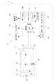
図3は、カメラ付き携帯電話1のハードウエア構成を簡単に示した略ブロック図である。カメラ付き携帯電話1は、大きくは電話モジュール9とカメラモジュール7から構成される。電話モジュール9はCPU10を備え、CPU10にディスプレイ11,キーパッド12,加速度センサ13a,ジャイロセンサ13b,ベースバンド処理部14,DRAM17,フラッシュメモリ18などが接続されている。フラッシュメモリ18にはカメラ付き携帯電話1のオペレーティングシステム(OS)21が格納されており、OS21とCPU10は協働して、カメラ付き携帯電話1の動作を制御する制御装置を構成する。またフラッシュメモリ18には、カメラ付き携帯電話1のOCR機能を司るコンピュータ・プログラムであるOCRソフトウエア19や、カメラ付き携帯電話1のメッセージング機能を司るMMSソフトウエア20など、様々なアプリケーションソフトウエア格納されている。これらのソフトウエアはCPU10や他のハードウエアと協働して、カメラ付き携帯電話1を特定の機能を有する情報処理装置として動作させる。ディスプレイ11は液晶画面2を有する。キーパッド12は、図1に示した機能キー3,左キー4,右キー5,テンキー6などの複数のキーを備える。加速度センサ13aは3軸の加速度センサであって、カメラ付き携帯電話1の傾きや直線的な動きを検出するために用いられる。ジャイロセンサ13bも3軸のジャイロセンサであり、カメラ付き携帯電話1の回転を検出するために用いられる。ベースバンド処理部14には、さらにRF処理部15及びアンテナ16が接続されており、これらは信号の送受信機能を担う。ベースバンド処理部14はデジタル変復調やエラー訂正などの機能を担当し、RF処理部15は搬送周波数への周波数変換などの機能を担当する。DRAM17はカメラ付き携帯電話1の主記憶装置として動作する。DRAMはフラッシュメモリよりもアクセス速度が速いため、カメラ付き携帯電話1の動作中にCPU10に使われる頻度の高いプログラムやデータが格納される。はじめフラッシュメモリ18に格納されていたOS21やアプリケーションソフトウエアも、動作時にはCPU10の中のキャッシュメモリやDRAM17に移されて(又はコピーされて)用いられることが多い。主記憶装置としては、SRAMやSDRAMを用いることができる。 FIG. 3 is a schematic block diagram simply showing the hardware configuration of the camera-equipped
カメラモジュール7は、レンズ22,レンズモータ23,CCDセンサ24,CCD駆動部25,前段処理部26,画像データ構築部27,バス28等を有する。レンズ22は入射した光をCCDセンサ24へ集める。レンズ22は図では1枚のレンズであるが、実際には複数枚のレンズが備わっていることが多い。レンズモータ23はレンズの位置を動かすために設けられ、ピント合わせや光学ズームのために用いられる。CCDセンサ24は、入射した光を電気信号に変換するセンサである。CCD駆動部25はCCDセンサ24によるデータ採取のタイミングや解像度を制御する。前段処理部26は、CCDセンサ24の出力信号に対してA/D変換を行ない、またホワイトバランスの調整を行なう。前段処理部26の出力信号は、まだ生のデータであり、一般のカメラ付き携帯電話やパソコン等で表示や印刷ができる形式ではない。画像データ構築部27は、前段処理部26の出力信号を、補間処理によってRGB又はYUV形式の画像データとして構築する。この画像データは、一般のカメラ付き携帯電話やパソコン等で表示・印刷されることが可能である。構築された画像データはデータインターフェース30によって電話モジュール9に送られる。 The camera module 7 includes a
CPU10は制御インターフェース29及びバス28を通じてレンズモータ23,CCD駆動部25,前段処理部26などに接続されている。このためCPU10は、レンズモータ23を制御してピントやズームを調整したり、CCD駆動部25を制御してデータ採取の解像度を変更したり、前段処理部26を通じて画像のホワイトバランスを制御することができる。写真を撮影する前に、写そうとする光景が液晶ディスプレイ11の画面2上にプレビュー表示される。プレビューモードのとき、CPU10は、CCDセンサ24が小さな解像度で、しかし1秒間に10回程度の頻度で撮影を行なうように、CCD駆動部25を制御する。従ってプレビューモードにおいて、ユーザーはカメラを通じて写される光景を、リアルタイムで画面2上に見ることができる。写真を撮影するときは、CPU10はCCD駆動部25を制御して、CCDセンサ24がその最大解像度でデータ採取を行なうようにする。 The
図4に、OCRソフトウエア19の構造を示す。OCRソフトウエア19は、領域選択モジュール33,カメラ制御モジュール34,OCRモジュール35,動き検出モジュール36という4つのソフトウエア・モジュールを備える。領域選択モジュール33は、OCRを行なう現実世界の領域を定めるためのユーザーインターフェースを提供する。ユーザーは、現実世界の光景を画面2で見ながら、現実世界に印を付けるようにして、OCR領域を選択することができる。領域選択モジュール33の詳細は図5と図6を参照して後に説明される。 FIG. 4 shows the structure of the
カメラ制御モジュール34は、CCDセンサ24で捉えられた光景をディスプレイ11に表示したり、領域選択モジュール33によって定められた領域の光景を撮影して画像データを取得するためのモジュールである。カメラ制御モジュール34は、カメラモジュール7を直接制御する命令を備える必要は必ずしもない。カメラモジュール7を直接制御する命令は、DRAM17やフラッシュメモリ18に格納されているOS21や別のカメラ制御ソフトウエアに組み込まれていてもよい。このような場合、カメラ制御モジュール34はカメラ制御ソフトウエアと命令やデータをやりとりできるソフトウエア・インターフェースを備えることができる。このようなソフトウエア・インターフェースには、「プレビュー画像を供給せよ」とか「指定領域のデータ採取を行なえ」などという、カメラ制御ソフトウエアへの指示を含むことができる。 The
OCRモジュール35は、カメラ制御モジュール34によって得られた画像データにOCRを適用し、文字情報を得るためのモジュールである。OCRのアルゴリズムは既に知られており、処理速度や電力消費・言語などの条件が合えば、如何なるアルゴリズムを用いてもよい。OCRモジュール35は、OCRによって得られた文字情報を、アプリケーション間又はアプリケーション内でデータを転送するための共有メモリ空間に保存する。このため、OCRソフトウエア19によって得られた文字情報は、カメラ付き携帯電話1にインストールされている、他の様々なアプリケーションから利用することができる。 The
動き検出モジュール36は、CPU10と協働して、連続したフレームを比較することによって、カメラ付き携帯電話1の動きを調べる画像処理プログラムを備える。さらに動き検出モジュール36は、加速度センサ13aとジャイロセンサ13bの出力信号からも、カメラ付き携帯電話1の動きを調べる。加速度センサ13aの出力信号は、カメラ付き携帯電話1の傾きや直線的な運動を知るため用いられる。ジャイロセンサ13bは、カメラ付き携帯電話1の回転運動を知るために用いられる。 The
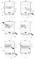
次に、OCRソフトウエア19の動作を図5と図6を用いてより詳細に説明する。図5はOCRソフトウエア19の動作を説明するためのフローチャートであり、図6はOCRソフトウエア19動作中における液晶画面2の表示の様子を描いた図である。図6(a)〜(f)には、カメラ付き携帯電話1のハードウエア要素として、液晶画面2と機能キー3,左キー4,右キー5のみが描かれている。 Next, the operation of the
まず、OCRソフトウエア19が起動する(ステップS1)。するとOCRソフトウエア19は、CPU10に指示を出し、カメラ付き携帯電話1をプレビューモードへセットする。OCRソフトウエア19の指示はOS21や他のカメラモジュール制御ソフトウエアに向けられる場合もある。CPU10は、OCRソフトウエア19や他のソフトウエアの指示に従って、カメラモジュール7が1秒間に10回程度、プレビュー用のデータ採取を行なうように制御し、得られた画像データを液晶画面2に表示する。このため、画面2には、現実世界の様子がリアルタイムで映し出される。このときの様子が図6(a)に示されている。 First, the
図6(a)は、OCRソフトウエア19が起動した直後の画面である。図6(a)を見ると、画面2の中にカメラモジュール7によって撮影される現実世界の光景41が表示されている。また、画面左下隅43には「メニュー」と書かれており、これは左キー4が押されると、領域選択モジュール33の機能にアクセスするためのメニューが表示されることを示している。画面右下隅45には「終了」と書かれており、これは右キー5が押されると、OCRソフトウエア19が終了することを示している。画面下中央44には「選択(1)」と書かれており、これは、機能キー3が押されると、OCRのための領域の始点が定められることを示している。光景41を見ると、画面中央領域に「These text are to be extracted」の文字情報が存在する領域42を見つけることができる。以下、この文字列をOCRによって文字情報として取得することを例に取り、OCRソフトウエア19の動作説明を続ける。 FIG. 6A shows a screen immediately after the
ステップ2において、領域選択モジュール33は、画面2に映し出される現実世界の特定の場所を選択するため、2組の変数を準備する。以下、それぞれ第1の変数と第2の変数と呼ぶ。各々の変数は、画面上の2次元又は3次元の座標を内部パラメータとして有し、その初期値は画面2の中央位置に対応している。 In
ステップS3において、領域選択モジュール33は、第1の変数の値に対応する画面2上の位置に、第1のポインタ71を表示するようにCPU10に指示する。第1のポインタ71は、OCRのための領域の始点を指定するために用いられる。第1の変数の初期値が画面中央に対応しているため、図6(a)に示されるように、第1のポインタ71は、はじめ画面中央に固定されている。そこでユーザーは、カメラ付き携帯電話1を方向47の方に手で動かすことで、OCRを行なうべき領域42の左上隅が画面2の中央に映されるように、カメラ付き携帯電話1の空間的な位置を調節する。図6(b)を参照のこと。調節が終わると、ユーザーは、機能キー3を押す。 In step S3, the
ステップS4において、領域選択モジュール33は、CPU10と協働し、機能キー3の押下を観測する状態に入っている。機能キー3が押されたことを検知すると、領域選択モジュール33は、第2の変数の値に対応する画面2上の位置、すなわち画面中央に、第2のポインタ72を表示するようにCPU10に指示する(ステップS5)(図6(c)参照)。第2のポインタ72は、OCRのための領域の終点を指定するために用いられる。そこでユーザーは、第2のポインタ72が領域42の右下隅が、画面中央に映し出されるように、カメラ付き携帯電話1を方向48の方へ手で動かす。ユーザーがカメラ付き携帯電話1を動かしている間、ユーザーは機能キー3を押したままである。 In step S <b> 4, the
このとき、領域選択モジュール33は、動き検出モジュール36を利用して、カメラ付き携帯電話1の動きを観測する状態に入っている(ステップS6)。カメラ付き携帯電話1が動かされたことを検知すると、領域選択モジュール33は、第1の変数の値をカメラ付き携帯電話1の動きを補償するように変化させ、さらに第1のポインタ71を第1の変数の新しい値に対応する画面2上の位置に表示し直すように、CPU10に指示する。この結果、第1のポインタは、方向48とは逆の方向49の向きに、画面2上を移動する。従って、第1のポインタ71がポイントしている光景41の場所は、カメラ付き携帯電話1が移動しても画面2上では変わらない。言葉を換えると、第1のポインタ71は、最初にポイントした現実世界の場所を、画面2上で追跡する。追跡精度は動き検出モジュール36の精度に依存する。このように画面2に映る光景は変化しても、図6(c)に示されるように、第1のポインタ71は、相変わらず領域42の左上隅をポイントしている。従ってステップS4においてユーザーが機能キーを押したことは、あたかも現実世界の一点に印を付けたような効果をもたらすこととなる。 At this time, the
第2の変数の値は画面中央を指しているので、第2のポインタ72もまた画面2の中央に固定されている。領域選択モジュール33は、第1の変数と第2の変数とで定まる画面2上の矩形領域73を、蛍光色などでハイライト表示するようにCPU10に指示する(ステップS8)。これにより、ユーザーは、選択しようとする領域のプレビューを現実世界の光景に重ねて確認することができる。 Since the value of the second variable points to the center of the screen, the
ユーザーが機能キーを押してOCR領域の始点を選択した後、画面2の中央下部44の表示は「選択(2)」と変わる。これは、機能キー3が離されると、OCR領域の終点が選択されることを示している。 After the user presses the function key to select the start point of the OCR area, the display at the center
ステップS9において、領域選択モジュール33は、CPU10と協働し、機能キー3が離されることを観測する。OCR領域の終点を選択するため、ユーザーは、領域42の右下隅が画面2の中央に表示されるように、カメラ付き携帯電話1を手で移動する。すると図6(d)に示すように、第2のポインタ72が領域42の右下隅をポイントする。第1のポインタ71は表示されていない。これは、第1の変数に対応する位置が、画面2の外にあるからである。 In step S9, the
機能キー3が離されたことを観測すると、領域選択モジュール33は、動き検出モジュール36を利用して、再びカメラ付き携帯電話1の動きを観測する状態に入る(ステップS11)。カメラ付き携帯電話1が動いたことを検知すると、領域選択モジュール33は、第1の変数と第2の変数の両方の値を、カメラ付き携帯電話1の動きを補償するように変化させる。さらに第1及び第2のポインタと、矩形領域73をそれぞれ第1の変数及び第2の変数の新しい値に対応する画面上の位置に表示し直すように、CPU10に指示する。この結果、矩形領域73内に表示される現実世界の光景は、カメラ付き携帯電話1が動かされても、変化しなくなる。ユーザーは、選択した現実世界の範囲を画面2の中で見ることができる。When it is observed that the
ユーザーが機能キー3を離してOCR領域の終点を選択した後、画面2の中央下部44の表示は「決定」と変わる。これは、次に機能キー3が押されると、矩形領域73がOCRのための領域として決定されることを示している。つまり、矩形領域73内の光景がカメラモジュール7によって撮影され、得られた画像データに対してOCRが適用される。そこで所望の文字列を得るには、図6(f)に示すように、矩形領域73を全て画面2に表示されるようにカメラ付き携帯電話1の空間位置を調節する必要がある。 After the user releases the
図6(e)に示されるように、ユーザーは、選択した領域73全てを画面2上に表示させるべく、カメラ付き携帯電話1を方向49の方へ動かす。すると、領域選択モジュール33は、第1のポインタ71や第2のポインタ72、矩形領域73を、カメラ付き携帯電話1の動きを補償するように、画面上を方向50の方へ移動する(ステップS12)。矩形領域73は、蛍光色などでハイライト表示される(ステップS13)。ユーザーは、画面が図6(f)の状態になるまでカメラ付き携帯電話1を動かす。 As shown in FIG. 6 (e), the user moves the camera-equipped
領域選択モジュール33は、再び機能キー3の押下を観測する(ステップS14)。機能キー3が押されると、領域選択モジュール33は、領域73を、OCR動作を行なう動作領域と定める(ステップS15)。このように、ユーザーは、簡単なキー操作と直感的な手の動きによって、現実世界の光景を画面2で見ながら、現実世界に印を付けるようにして、OCR領域を選択することができる。従って、非常に直感的かつ効率的なユーザーインターフェースが実現される。 The
続いてOCRソフトウエア19は、カメラ制御モジュール34によって上記動作領域の光景を撮影し、当該領域の画像データを構築するように、CPU10又はカメラモジュール7の制御プログラムに指示を出す(ステップS16)。当該処理領域内のみの情報を有する画像データを得るための実装方法には2つの方法が考えられる。その1つは、CCD駆動部25が、CPU10の制御によって、当該処理領域に対応する画素からのみデータ採取を行なうように、CCDセンサ24を制御する方法である。もう1つはCCDセンサ24の全ての画素を使って撮影を行ない、得られた画像データの中からCPU10が必要なデータのみを抽出する方法である。Subsequently, the
さらにOCRソフトウエア19は、加速度センサ13aから加速度情報を得るようにCPU10に指示を出す。得られた加速度情報は、カメラ付き携帯電話1の傾きを表しており、ステップS16で得られた画像データを補正するために用いられる(ステップS17)。傾きを補正することにより、OCRの精度を向上させることが期待できる。なお、加速度センサ13aを用いた傾き補正機能は、ユーザーの選択により無効にできるようにすることができる。 Further, the
ステップS18では、OCRソフトウエア19のOCRモジュール35がCPU10と協働して、カメラ制御モジュール34によって得られた画像データにOCRを適用し、文字情報を抽出する。OCRのアルゴリズムは既に知られており、処理速度や電力消費・言語などの条件が合えば、如何なるアルゴリズムを用いてもよい。このOCR処理によって、図6(f)で符号73で示された領域の光景に存在した、「These text are to be extracted」という文字情報が抽出されることができる。さらにOCRモジュール35は、OCRによって得られた文字情報を、アプリケーション間又はアプリケーション内でデータを転送するための共有メモリ空間に保存するように、CPU10に指示する(ステップS19)。このため、OCRソフトウエア19によって得られた文字情報は、カメラ付き携帯電話1にインストールされている、様々なアプリケーションから利用することができる。このようなアプリケーションとは、例えばテキストエディタ、ワードプロセッサ、電子メモ、メッセージングアプリケーション、インターネットブラウザなどである。共有メモリ空間はDRAM17の中に設けられる。ステップS25ではOCRソフトウエア19が動作を終了する。 In step S18, the
なお、ステップS6やステップS11において、動き検出モジュール36が、カメラ付き携帯電話1の動きの大きさが所定の閾値を越えたことを検出した場合は、画面2にエラーメッセージを表示し(ステップS21)、機能キー3が押されると、OCRソフトウエア19を初期化する(ステップS22)。これは、そのような大きな動きが、動き検出モジュール36の正確性を保証することが困難にするからである。 In step S6 or step S11, when the
このように、本発明によるカメラ付き携帯電話1は、OCR動作のために選択した領域を、現実世界の光景に画面2の中で重ねて見ることを可能とし、従ってユーザーが現実世界と処理領域との関係を直感的に理解することを可能とする。さらに本発明によるカメラ付き携帯電話1においては、OCRのための処理領域の設定から画像データ採取、OCRの実行までの全ての処理が、機能キー3を押して離すという単純なキー操作によって完了する。このためユーザーは、直感的かつ効率的に現実世界の文字情報に関わることができ、また直感的かつ効率的に現実世界の文字情報をカメラ付き携帯電話1に取り込むことが可能となる。このような文字情報は、単なるテキストである他に、E−mailアドレス、URL、電話番号など、様々であることができる。取り込んだ文字情報は、電子メモやMMS等のアプリケーションに貼付けることができる。このようにカメラ付き携帯電話1は、あたかもパーソナル・コンピュータにおけるコピー&ペースト操作のような方法で、現実世界の情報を取得することができる。 As described above, the camera-equipped
別の実施態様において、領域選択モジュール33は、次のように構成することもできる。In another embodiment, the
領域選択モジュール33は、起動すると変数を1つ準備する。図7(a)に示されるように、領域選択モジュール33は、その変数の初期値に対応する画面2の中央にポインタ81を表示する。ユーザーは、選択したい現実世界の領域の中央が、画面中央に映し出されるようにカメラ付き携帯電話1を手で動かして調節し、機能キー3を押す。 When activated, the
機能キー3が押されると、領域選択モジュール33は、動き検出モジュール36の助けを借りて、上記変数の値をカメラ付き携帯電話1の動きを補償するように変化させる。さらに領域選択モジュール33は、ポインタ81を上記変数の新しい値に対応する画面2上の位置に表示し直すように、CPU10に指示する。従って、ポインタ81がポイントする現実世界の場所は、カメラ付き携帯電話1が動いても変化しない。図7(b)を参照する。ユーザーが、機能キー3を押したまま、カメラ付き携帯電話1を下方向55に動かすと、ポインタ81は画面の上方向56に移動する。 When the
領域選択モジュール33は、ポインタ81の初期位置に輝点82を表示し続ける。さらに領域選択モジュール33は、ポインタ81と輝点82との距離を半径とし、ポインタ81の位置を中心とする楕円83を画面2上に表示するように、CPU10に指示する。楕円83は蛍光色でハイライト表示される。ポインタ81が動くと楕円83の位置も更新される。従って、楕円83が囲む現実世界の場所は、カメラ付き携帯電話1が動いても変化しない。 The
ユーザーが機能キー3を離すと、領域選択モジュール33は、楕円83の半径を固定する。領域選択モジュール33は、ポインタ81を、カメラ付き携帯電話1の動きを補償するように画面2上を移動させ続け、それに伴って楕円83も画面2上を移動させられる。ユーザーは、楕円83が画面2上の適当な位置に来るようにカメラ付き携帯電話1を手で動かして調節する(図7(c)参照)。 When the user releases the
カメラ付き携帯電話1は、楕円83で囲まれた領域を、ピント及びホワイトバランスを調節する領域として利用する。楕円83が移動すると、CPU10は、レンズモータ23及び前段処理部26を制御して、ピントやホワイトバランスを調節し直す。従ってユーザーは、画面2 のどの場所に対してもピントやホワイトバランスを合わせることができる。ユーザーは機能キー3を再び押すと、画面2に映る光景を写真に撮影することができる。 The camera-equipped
このように、ユーザーは、簡単なキー操作と直感的な手の動きによって、現実世界の光景を画面2で見ながら、現実世界に印を付けるようにして、ピントを合わせる領域を選択することができる。従って、非常に直感的かつ効率的なユーザーインターフェースが実現される。 In this way, the user can select an area to be focused by marking the real world while viewing the real world scene on the
以上、本発明を好適な実施例を用いて説明したが、本発明の実施態様は他にも様々なバリエーションがあり、本発明の範囲内で様々な変形が可能である。例えば、領域選択モジュール33や動き検出モジュール36は、別のソフトウエアから呼び出されて用いられることも可能である。また領域選択モジュール33によって指定された液晶画面2上の領域は、当該領域の写真を撮る必要のない目的にも使用されうる。例えばOS21やカメラモジュール7の制御ソフトウエアは、当該領域を、ピントを合わせたりホワイトバランスを調節したりする領域として用いることができる。また、当該選択領域の内部を電子ズームで拡大するような利用も可能である。さらに、写真に当該領域内のみ色やフレームを付けるという利用も可能である。さらにカメラ付き携帯電話1は、加速度センサのみならず、ジャイロセンサや磁気センサを備え、これらの出力を撮影した画像の補正に用いるように構成することもできる。本発明による電子装置は、領域選択モジュール33を使用する機能を2つ以上備えていてもよい。このような実施態様では、電子装置は機能を切り替えるユーザーインターフェースを備える必要がある。例えば、当該動作領域の画像データにOCRをかける動作とMMSやE−mail等のメッセージングアプリケーションによって送信する準備をする動作とを切り替えることができるように、本発明による電子装置を構成することが可能である。 As mentioned above, although this invention was demonstrated using the suitable Example, the embodiment of this invention has various other variations, and various deformation | transformation are possible within the scope of the present invention. For example, the
1 カメラ付き携帯電話
2 液晶画面
3 機能キー
4 左キー
5 右キー
6 テンキー
7 カメラモジュール
18 フラッシュメモリ
19 OCRソフトウエア
21 オペレーティングシステム
22 レンズ
23 レンズモータ
24 CCDセンサ
25 CCD駆動部
26 前段処理部
27 画像データ構築部
28 バス28
33 領域選択モジュール
34 撮影モジュール
35 OCRモジュールDESCRIPTION OF
33
Claims (21)
Translated fromJapanese・ 撮像素子と、
・ 前記撮像素子を用いて得られる映像を表示するスクリーンと、
・ 前記電子装置の動きを検出する動き検出手段と、
・ 前記スクリーン上の位置に関連すると共に所定の選択動作に関連する変数と、
を有し、さらに、
・ 前記選択操作を契機として、前記電子装置の動きを補償するように前記動き検出手段を利用して前記変数の値を刻々と変化させ、
・ 前記変数の値に基づき前記電子装置の動作に関する動作領域を定める
ように構成される、電子装置。An electronic device,
An image sensor;
A screen for displaying an image obtained using the image sensor;
A motion detection means for detecting the motion of the electronic device;
A variable related to the position on the screen and to a predetermined selection action;
In addition,
-Triggered by the selection operation, the value of the variable is changed every moment using the motion detection means so as to compensate for the motion of the electronic device,
An electronic device configured to define an operating area for the operation of the electronic device based on the value of the variable;
・ 前記スクリーン上の位置に関連すると共に所定の選択動作に関連する変数とをさらに有し、
さらに、
・ 前記選択操作を契機として、前記電子装置の動きを補償するように前記動き検出手段を利用して前記変数の値を刻々と変化させ、
・ 前記変数の値に基づき前記コンピュータ・プログラムの機能に関する動作領域を定める
ように、前記電子装置に指示するように構成される、コンピュータ・プログラム。A computer program for an electronic apparatus, comprising: an image sensor; a screen that displays an image obtained using the image sensor; and a motion detection unit that detects a motion of the electronic apparatus. ,
A variable related to a position on the screen and related to a predetermined selection action;
further,
-Triggered by the selection operation, the value of the variable is changed every moment using the motion detection means so as to compensate for the motion of the electronic device,
A computer program configured to instruct the electronic device to define an operating area relating to the function of the computer program based on the value of the variable.
・ 前記変数の値に関連する位置を前記スクリーン上に標示するように前記電子装置に指示する手段と、
・ 前記変数の値に基づいて前記スクリーン領域を定め、前記スクリーン領域を前記スクリーン上に標示するように前記電子装置に指示する手段と、
を備えるコンピュータ・プログラム。A computer program according to claim 15 or 16, comprising:
Means for instructing the electronic device to mark on the screen a position associated with the value of the variable;
Means for defining the screen area based on the value of the variable and instructing the electronic device to mark the screen area on the screen;
A computer program comprising:
・ 前記機能は、前記動作領域の光景を前記撮像素子で撮影して画像データを取得するように前記電子装置に指示する手段と、
・ 前記電子装置と協働して前記画像データからOCR処理によって文字情報を抽出する手段と、
を備えるコンピュータ・プログラム。A computer program according to claim 15-18, comprising:
The function includes means for instructing the electronic device to capture a scene of the operation area with the imaging device and obtain image data;
Means for extracting character information from the image data by OCR processing in cooperation with the electronic device;
A computer program comprising:
・ 前記スクリーン上の位置に関連すると共に所定の選択動作に関連する変数を準備し、
さらに、
・ 前記選択操作を契機として、前記電子装置の動きを補償するように前記動き検出手段を利用して前記変数の値を刻々と変化させるステップと、
・ 前記変数の値に基づき前記動作領域を定めるステップと、
を備える方法。An electronic device comprising an imaging device, a screen that displays an image obtained by using the imaging device, and a motion detection unit that detects motion of the electronic device, and defines an operation region related to an operation of the electronic device. A method,
Providing variables related to the position on the screen and to a predetermined selection action;
further,
The step of changing the value of the variable every moment using the motion detection means so as to compensate for the motion of the electronic device triggered by the selection operation;
Determining the operating region based on the value of the variable;
A method comprising:
Priority Applications (3)
| Application Number | Priority Date | Filing Date | Title |
|---|---|---|---|
| JP2005119084AJP2006303651A (en) | 2005-04-15 | 2005-04-15 | Electronic equipment |
| PCT/JP2006/308254WO2006112490A1 (en) | 2005-04-15 | 2006-04-13 | Electronic device |
| US11/887,177US20090227283A1 (en) | 2005-04-15 | 2006-04-13 | Electronic device |
Applications Claiming Priority (1)
| Application Number | Priority Date | Filing Date | Title |
|---|---|---|---|
| JP2005119084AJP2006303651A (en) | 2005-04-15 | 2005-04-15 | Electronic equipment |
Publications (1)
| Publication Number | Publication Date |
|---|---|
| JP2006303651Atrue JP2006303651A (en) | 2006-11-02 |
Family
ID=36570386
Family Applications (1)
| Application Number | Title | Priority Date | Filing Date |
|---|---|---|---|
| JP2005119084APendingJP2006303651A (en) | 2005-04-15 | 2005-04-15 | Electronic equipment |
Country Status (3)
| Country | Link |
|---|---|
| US (1) | US20090227283A1 (en) |
| JP (1) | JP2006303651A (en) |
| WO (1) | WO2006112490A1 (en) |
Cited By (2)
| Publication number | Priority date | Publication date | Assignee | Title |
|---|---|---|---|---|
| JP2013077302A (en)* | 2011-09-29 | 2013-04-25 | Samsung Electronics Co Ltd | User interface providing method and device of portable terminal |
| JP2019057209A (en)* | 2017-09-22 | 2019-04-11 | Line株式会社 | Program, information processing method, and information processing apparatus |
Families Citing this family (23)
| Publication number | Priority date | Publication date | Assignee | Title |
|---|---|---|---|---|
| US7697827B2 (en) | 2005-10-17 | 2010-04-13 | Konicek Jeffrey C | User-friendlier interfaces for a camera |
| US8103558B2 (en)* | 2007-07-23 | 2012-01-24 | At&T Intellectual Property I, L.P. | Methods, systems, and computer-readable media for placing orders |
| EP2136317B1 (en)* | 2008-06-19 | 2013-09-04 | Samsung Electronics Co., Ltd. | Method and apparatus for recognizing characters |
| US7953462B2 (en) | 2008-08-04 | 2011-05-31 | Vartanian Harry | Apparatus and method for providing an adaptively responsive flexible display device |
| KR20100120753A (en)* | 2009-05-07 | 2010-11-17 | (주)실리콘화일 | Image sensor and image sensing method for character recognition |
| US9176542B2 (en)* | 2009-11-06 | 2015-11-03 | Sony Corporation | Accelerometer-based touchscreen user interface |
| EP2383970B1 (en)* | 2010-04-30 | 2013-07-10 | beyo GmbH | Camera based method for text input and keyword detection |
| WO2011158336A1 (en)* | 2010-06-15 | 2011-12-22 | 株式会社ナビタイムジャパン | Navigation system, terminal apparatus, navigation server, navigation apparatus, navigation method, and program |
| US9158983B2 (en) | 2010-07-08 | 2015-10-13 | E-Image Data Corporation | Microform word search method and apparatus |
| TW201222429A (en)* | 2010-11-23 | 2012-06-01 | Inventec Corp | Web camera device and operating method thereof |
| US20120298738A1 (en)* | 2011-05-25 | 2012-11-29 | Nukotoys, Inc. | Cards with geometrically defined card use and mechanics |
| US8488916B2 (en)* | 2011-07-22 | 2013-07-16 | David S Terman | Knowledge acquisition nexus for facilitating concept capture and promoting time on task |
| US20130022270A1 (en)* | 2011-07-22 | 2013-01-24 | Todd Kahle | Optical Character Recognition of Text In An Image for Use By Software |
| KR101834987B1 (en)* | 2011-08-08 | 2018-03-06 | 삼성전자주식회사 | Apparatus and method for capturing screen in portable terminal |
| US20130038756A1 (en)* | 2011-08-08 | 2013-02-14 | Samsung Electronics Co., Ltd. | Life-logging and memory sharing |
| EP2637128B1 (en) | 2012-03-06 | 2018-01-17 | beyo GmbH | Multimodal text input by a keyboard/camera text input module replacing a conventional keyboard text input module on a mobile device |
| US9298980B1 (en)* | 2013-03-07 | 2016-03-29 | Amazon Technologies, Inc. | Image preprocessing for character recognition |
| US9179061B1 (en)* | 2013-12-11 | 2015-11-03 | A9.Com, Inc. | Assisted text input for computing devices |
| US9146106B2 (en)* | 2013-12-11 | 2015-09-29 | Trimble Navigation Limited | Laser receiver using a smart device |
| GB2525232A (en)* | 2014-04-17 | 2015-10-21 | Nokia Technologies Oy | A device orientation correction method for panorama images |
| DE102016119071A1 (en)* | 2016-10-07 | 2018-04-12 | pixolus GmbH | image capture |
| CN107864273A (en)* | 2017-10-26 | 2018-03-30 | 珠海市魅族科技有限公司 | A kind of information acquisition method, device, computer installation and storage medium |
| USD1053190S1 (en)* | 2022-05-30 | 2024-12-03 | ShenZhen ORICO Technologies Co., Ltd. | Hard disk drive |
Citations (8)
| Publication number | Priority date | Publication date | Assignee | Title |
|---|---|---|---|---|
| JPH03256460A (en)* | 1990-03-07 | 1991-11-15 | Hitachi Ltd | Image oscillation correction |
| JPH11281327A (en)* | 1998-03-30 | 1999-10-15 | Mitsutoyo Corp | Method for measuring line width and device therefor |
| JP2001036901A (en)* | 1999-07-15 | 2001-02-09 | Canon Inc | Image processing apparatus, image processing method, and memory medium |
| JP2002027291A (en)* | 2000-04-29 | 2002-01-25 | Hewlett Packard Co <Hp> | Multiframe panning method having visual feedback |
| JP2002352190A (en)* | 2001-05-28 | 2002-12-06 | Kenwood Corp | Portable terminal device |
| JP2003006277A (en)* | 2001-06-22 | 2003-01-10 | Iida Sangyo:Kk | Process management server system, which enables to monitor on-site image on real time |
| JP2004145736A (en)* | 2002-10-25 | 2004-05-20 | Canon Software Inc | Character recognition device, character recognition data output method, program and recording medium |
| JP2005084951A (en)* | 2003-09-09 | 2005-03-31 | Hitachi Ltd | Information processing apparatus, information processing method, and software |
Family Cites Families (12)
| Publication number | Priority date | Publication date | Assignee | Title |
|---|---|---|---|---|
| US5867144A (en)* | 1991-11-19 | 1999-02-02 | Microsoft Corporation | Method and system for the direct manipulation of information, including non-default drag and drop operation |
| JP3727954B2 (en)* | 1993-11-10 | 2005-12-21 | キヤノン株式会社 | Imaging device |
| JPH07288722A (en)* | 1994-04-15 | 1995-10-31 | Canon Inc | Imaging device |
| JP2000194693A (en)* | 1998-12-28 | 2000-07-14 | Nec Corp | Character conversion device and method |
| US7187412B1 (en)* | 2000-01-18 | 2007-03-06 | Hewlett-Packard Development Company, L.P. | Pointing device for digital camera display |
| JP2003178067A (en)* | 2001-12-10 | 2003-06-27 | Mitsubishi Electric Corp | Mobile terminal type image processing system, mobile terminal and server |
| US7221796B2 (en)* | 2002-03-08 | 2007-05-22 | Nec Corporation | Character input device, character input method and character input program |
| JP2003288161A (en)* | 2002-03-28 | 2003-10-10 | Nec Corp | Mobile tool |
| JP4113387B2 (en)* | 2002-07-24 | 2008-07-09 | シャープ株式会社 | Portable terminal device, information reading program, and recording medium recording the program |
| AU2003303787A1 (en)* | 2003-01-22 | 2004-08-13 | Nokia Corporation | Image control |
| JP4038771B2 (en)* | 2003-10-28 | 2008-01-30 | ソニー株式会社 | Portable information terminal device, information processing method, recording medium, and program |
| US8537224B2 (en)* | 2005-01-31 | 2013-09-17 | Hewlett-Packard Development Company, L.P. | Image capture device having a shake metter |
- 2005
- 2005-04-15JPJP2005119084Apatent/JP2006303651A/enactivePending
- 2006
- 2006-04-13USUS11/887,177patent/US20090227283A1/ennot_activeAbandoned
- 2006-04-13WOPCT/JP2006/308254patent/WO2006112490A1/enactiveApplication Filing
Patent Citations (8)
| Publication number | Priority date | Publication date | Assignee | Title |
|---|---|---|---|---|
| JPH03256460A (en)* | 1990-03-07 | 1991-11-15 | Hitachi Ltd | Image oscillation correction |
| JPH11281327A (en)* | 1998-03-30 | 1999-10-15 | Mitsutoyo Corp | Method for measuring line width and device therefor |
| JP2001036901A (en)* | 1999-07-15 | 2001-02-09 | Canon Inc | Image processing apparatus, image processing method, and memory medium |
| JP2002027291A (en)* | 2000-04-29 | 2002-01-25 | Hewlett Packard Co <Hp> | Multiframe panning method having visual feedback |
| JP2002352190A (en)* | 2001-05-28 | 2002-12-06 | Kenwood Corp | Portable terminal device |
| JP2003006277A (en)* | 2001-06-22 | 2003-01-10 | Iida Sangyo:Kk | Process management server system, which enables to monitor on-site image on real time |
| JP2004145736A (en)* | 2002-10-25 | 2004-05-20 | Canon Software Inc | Character recognition device, character recognition data output method, program and recording medium |
| JP2005084951A (en)* | 2003-09-09 | 2005-03-31 | Hitachi Ltd | Information processing apparatus, information processing method, and software |
Cited By (3)
| Publication number | Priority date | Publication date | Assignee | Title |
|---|---|---|---|---|
| JP2013077302A (en)* | 2011-09-29 | 2013-04-25 | Samsung Electronics Co Ltd | User interface providing method and device of portable terminal |
| JP2019057209A (en)* | 2017-09-22 | 2019-04-11 | Line株式会社 | Program, information processing method, and information processing apparatus |
| JP7029913B2 (en) | 2017-09-22 | 2022-03-04 | Line株式会社 | Programs, information processing methods, and information processing equipment |
Also Published As
| Publication number | Publication date |
|---|---|
| WO2006112490A1 (en) | 2006-10-26 |
| US20090227283A1 (en) | 2009-09-10 |
Similar Documents
| Publication | Publication Date | Title |
|---|---|---|
| JP2006303651A (en) | Electronic equipment | |
| JP7169383B2 (en) | Capture and user interface using night mode processing | |
| JP5359762B2 (en) | Information processing apparatus, display control method, and display control program | |
| JP4510713B2 (en) | Digital camera | |
| KR102032347B1 (en) | Image display positioning using image sensor location | |
| WO2021244455A1 (en) | Image content removal method and related apparatus | |
| JP2023501663A (en) | Filming method and electronic device | |
| WO2021219141A1 (en) | Photographing method, graphic user interface, and electronic device | |
| JPH10240436A (en) | Information processing device and recording medium | |
| JPWO2016035421A1 (en) | Pan / tilt operating device, camera system, pan / tilt operating program, and pan / tilt operating method | |
| JPWO2016038971A1 (en) | Imaging control apparatus, imaging control method, camera, camera system, and program | |
| KR20140106265A (en) | Apparatus and method for processing a image in device | |
| JP2008003335A (en) | Imaging apparatus, focus control method, and focus control program | |
| EP4287610A1 (en) | Focusing method and apparatus, electronic device, and medium | |
| JP5407380B2 (en) | Mobile terminal with imaging function | |
| WO2021013147A1 (en) | Video processing method, device, terminal, and storage medium | |
| JP2014146989A (en) | Image pickup device, image pickup method, and image pickup program | |
| JP2010268019A (en) | Imaging device | |
| WO2022228259A1 (en) | Target tracking method and related apparatus | |
| WO2018196854A1 (en) | Photographing method, photographing apparatus and mobile terminal | |
| KR20050109190A (en) | Wide image generating apparatus and method using a dual camera | |
| JP2009171428A (en) | Control method and program for digital camera apparatus and electronic zoom | |
| CN107211090B (en) | Operating device, tracking system, operating method and medium | |
| US9691362B2 (en) | Display control apparatus, display control method, and recording medium displaying frames indicating portions of an image | |
| CN117119276A (en) | Underwater shooting method and electronic equipment |
Legal Events
| Date | Code | Title | Description |
|---|---|---|---|
| A621 | Written request for application examination | Free format text:JAPANESE INTERMEDIATE CODE: A621 Effective date:20080327 | |
| A131 | Notification of reasons for refusal | Free format text:JAPANESE INTERMEDIATE CODE: A131 Effective date:20100430 | |
| A02 | Decision of refusal | Free format text:JAPANESE INTERMEDIATE CODE: A02 Effective date:20101018 |