JP2006302556A - Semiconductor element manufacturing method, semiconductor element, electronic device, and electronic apparatus - Google Patents
Semiconductor element manufacturing method, semiconductor element, electronic device, and electronic apparatusDownload PDFInfo
- Publication number
- JP2006302556A JP2006302556AJP2005119328AJP2005119328AJP2006302556AJP 2006302556 AJP2006302556 AJP 2006302556AJP 2005119328 AJP2005119328 AJP 2005119328AJP 2005119328 AJP2005119328 AJP 2005119328AJP 2006302556 AJP2006302556 AJP 2006302556A
- Authority
- JP
- Japan
- Prior art keywords
- layer
- group
- semiconductor
- hole transport
- electrode
- Prior art date
- Legal status (The legal status is an assumption and is not a legal conclusion. Google has not performed a legal analysis and makes no representation as to the accuracy of the status listed.)
- Withdrawn
Links
- 239000004065semiconductorSubstances0.000titleclaimsabstractdescription114
- 238000004519manufacturing processMethods0.000titleclaimsabstractdescription53
- 239000000463materialSubstances0.000claimsabstractdescription153
- 230000005525hole transportEffects0.000claimsabstractdescription132
- 238000000034methodMethods0.000claimsabstractdescription107
- 229920000642polymerPolymers0.000claimsabstractdescription67
- 230000008569processEffects0.000claimsabstractdescription16
- 230000000379polymerizing effectEffects0.000claimsabstractdescription15
- 239000010410layerSubstances0.000claimsdescription350
- 150000001875compoundsChemical class0.000claimsdescription149
- 125000001424substituent groupChemical group0.000claimsdescription98
- 238000006116polymerization reactionMethods0.000claimsdescription29
- 125000002496methyl groupChemical group[H]C([H])([H])*0.000claimsdescription28
- 238000010438heat treatmentMethods0.000claimsdescription26
- 125000004435hydrogen atomChemical group[H]*0.000claimsdescription24
- 125000000623heterocyclic groupChemical group0.000claimsdescription22
- 125000001495ethyl groupChemical group[H]C([H])([H])C([H])([H])*0.000claimsdescription21
- 229910052799carbonInorganic materials0.000claimsdescription20
- 125000004432carbon atomChemical groupC*0.000claimsdescription20
- 239000012044organic layerSubstances0.000claimsdescription20
- OKTJSMMVPCPJKN-UHFFFAOYSA-NCarbonChemical compound[C]OKTJSMMVPCPJKN-UHFFFAOYSA-N0.000claimsdescription19
- 125000000217alkyl groupChemical group0.000claimsdescription9
- 239000007791liquid phaseSubstances0.000claimsdescription8
- 230000009477glass transitionEffects0.000claimsdescription3
- 230000010354integrationEffects0.000claimsdescription2
- 125000002029aromatic hydrocarbon groupChemical group0.000claims2
- 230000001131transforming effectEffects0.000abstract1
- -1polyethylene terephthalatePolymers0.000description61
- 239000000758substrateSubstances0.000description56
- 238000000576coating methodMethods0.000description43
- 239000010408filmSubstances0.000description42
- 239000003431cross linking reagentSubstances0.000description40
- 239000011248coating agentSubstances0.000description36
- 239000000126substanceSubstances0.000description29
- 239000002904solventSubstances0.000description25
- 239000007787solidSubstances0.000description23
- 239000004593EpoxySubstances0.000description20
- WFDIJRYMOXRFFG-UHFFFAOYSA-Nacetic acid anhydrideNatural productsCC(=O)OC(C)=OWFDIJRYMOXRFFG-UHFFFAOYSA-N0.000description16
- 150000004945aromatic hydrocarbonsChemical group0.000description16
- 239000011347resinSubstances0.000description16
- 229920005989resinPolymers0.000description16
- CTQNGGLPUBDAKN-UHFFFAOYSA-NO-XyleneChemical compoundCC1=CC=CC=C1CCTQNGGLPUBDAKN-UHFFFAOYSA-N0.000description14
- 230000000052comparative effectEffects0.000description14
- 229910052757nitrogenInorganic materials0.000description14
- 239000008096xyleneSubstances0.000description14
- 239000011241protective layerSubstances0.000description13
- KWYUFKZDYYNOTN-UHFFFAOYSA-MPotassium hydroxideChemical compound[OH-].[K+]KWYUFKZDYYNOTN-UHFFFAOYSA-M0.000description12
- 230000006870functionEffects0.000description12
- 239000003505polymerization initiatorSubstances0.000description12
- QTBSBXVTEAMEQO-UHFFFAOYSA-NAcetic acidChemical compoundCC(O)=OQTBSBXVTEAMEQO-UHFFFAOYSA-N0.000description11
- 239000012298atmosphereSubstances0.000description11
- 125000001997phenyl groupChemical group[H]C1=C([H])C([H])=C(*)C([H])=C1[H]0.000description11
- 238000004528spin coatingMethods0.000description11
- ZMXDDKWLCZADIW-UHFFFAOYSA-NN,N-DimethylformamideChemical compoundCN(C)C=OZMXDDKWLCZADIW-UHFFFAOYSA-N0.000description10
- YTPLMLYBLZKORZ-UHFFFAOYSA-NThiopheneChemical compoundC=1C=CSC=1YTPLMLYBLZKORZ-UHFFFAOYSA-N0.000description10
- 229910052751metalInorganic materials0.000description10
- 239000002184metalSubstances0.000description10
- UHOVQNZJYSORNB-UHFFFAOYSA-NBenzeneChemical compoundC1=CC=CC=C1UHOVQNZJYSORNB-UHFFFAOYSA-N0.000description9
- 239000002612dispersion mediumSubstances0.000description9
- XLYOFNOQVPJJNP-UHFFFAOYSA-NwaterSubstancesOXLYOFNOQVPJJNP-UHFFFAOYSA-N0.000description9
- 230000015572biosynthetic processEffects0.000description8
- MHDVGSVTJDSBDK-UHFFFAOYSA-Ndibenzyl etherChemical groupC=1C=CC=CC=1COCC1=CC=CC=C1MHDVGSVTJDSBDK-UHFFFAOYSA-N0.000description8
- 230000003993interactionEffects0.000description8
- PHTQWCKDNZKARW-UHFFFAOYSA-NisoamylolChemical compoundCC(C)CCOPHTQWCKDNZKARW-UHFFFAOYSA-N0.000description8
- 239000000203mixtureSubstances0.000description8
- BWHMMNNQKKPAPP-UHFFFAOYSA-Lpotassium carbonateChemical compound[K+].[K+].[O-]C([O-])=OBWHMMNNQKKPAPP-UHFFFAOYSA-L0.000description8
- 238000001771vacuum depositionMethods0.000description8
- UJOBWOGCFQCDNV-UHFFFAOYSA-N9H-carbazoleChemical compoundC1=CC=C2C3=CC=CC=C3NC2=C1UJOBWOGCFQCDNV-UHFFFAOYSA-N0.000description7
- NIXOWILDQLNWCW-UHFFFAOYSA-MAcrylateChemical compound[O-]C(=O)C=CNIXOWILDQLNWCW-UHFFFAOYSA-M0.000description7
- 229910045601alloyInorganic materials0.000description7
- 239000000956alloySubstances0.000description7
- UTTHLMXOSUFZCQ-UHFFFAOYSA-Nbenzene-1,3-dicarbohydrazideChemical compoundNNC(=O)C1=CC=CC(C(=O)NN)=C1UTTHLMXOSUFZCQ-UHFFFAOYSA-N0.000description7
- 239000000470constituentSubstances0.000description7
- 230000000694effectsEffects0.000description7
- 239000011521glassSubstances0.000description7
- 125000002887hydroxy groupChemical group[H]O*0.000description7
- 238000002347injectionMethods0.000description7
- 239000007924injectionSubstances0.000description7
- 238000002360preparation methodMethods0.000description7
- 239000000243solutionSubstances0.000description7
- ZWEHNKRNPOVVGH-UHFFFAOYSA-N2-ButanoneChemical compoundCCC(C)=OZWEHNKRNPOVVGH-UHFFFAOYSA-N0.000description6
- RTZKZFJDLAIYFH-UHFFFAOYSA-NDiethyl etherChemical compoundCCOCCRTZKZFJDLAIYFH-UHFFFAOYSA-N0.000description6
- HEMHJVSKTPXQMS-UHFFFAOYSA-MSodium hydroxideChemical compound[OH-].[Na+]HEMHJVSKTPXQMS-UHFFFAOYSA-M0.000description6
- WYURNTSHIVDZCO-UHFFFAOYSA-NTetrahydrofuranChemical compoundC1CCOC1WYURNTSHIVDZCO-UHFFFAOYSA-N0.000description6
- MWPLVEDNUUSJAV-UHFFFAOYSA-NanthraceneChemical compoundC1=CC=CC2=CC3=CC=CC=C3C=C21MWPLVEDNUUSJAV-UHFFFAOYSA-N0.000description6
- 239000011203carbon fibre reinforced carbonSubstances0.000description6
- 238000006243chemical reactionMethods0.000description6
- 125000003700epoxy groupChemical group0.000description6
- 238000003384imaging methodMethods0.000description6
- RAXXELZNTBOGNW-UHFFFAOYSA-NimidazoleNatural productsC1=CNC=N1RAXXELZNTBOGNW-UHFFFAOYSA-N0.000description6
- 238000001819mass spectrumMethods0.000description6
- 229910052760oxygenInorganic materials0.000description6
- 229920000768polyaminePolymers0.000description6
- GPYDMVZCPRONLW-UHFFFAOYSA-N1-iodo-4-(4-iodophenyl)benzeneChemical groupC1=CC(I)=CC=C1C1=CC=C(I)C=C1GPYDMVZCPRONLW-UHFFFAOYSA-N0.000description5
- 229910017073AlLiInorganic materials0.000description5
- RYGMFSIKBFXOCR-UHFFFAOYSA-NCopperChemical compound[Cu]RYGMFSIKBFXOCR-UHFFFAOYSA-N0.000description5
- YMWUJEATGCHHMB-UHFFFAOYSA-NDichloromethaneChemical compoundClCClYMWUJEATGCHHMB-UHFFFAOYSA-N0.000description5
- YGYAWVDWMABLBF-UHFFFAOYSA-NPhosgeneChemical compoundClC(Cl)=OYGYAWVDWMABLBF-UHFFFAOYSA-N0.000description5
- 125000003647acryloyl groupChemical groupO=C([*])C([H])=C([H])[H]0.000description5
- 125000002947alkylene groupChemical group0.000description5
- 239000011230binding agentSubstances0.000description5
- 239000010406cathode materialSubstances0.000description5
- 239000003999initiatorSubstances0.000description5
- 239000007788liquidSubstances0.000description5
- NIHNNTQXNPWCJQ-UHFFFAOYSA-No-biphenylenemethaneNatural productsC1=CC=C2CC3=CC=CC=C3C2=C1NIHNNTQXNPWCJQ-UHFFFAOYSA-N0.000description5
- AHLBNYSZXLDEJQ-FWEHEUNISA-NorlistatChemical compoundCCCCCCCCCCC[C@H](OC(=O)[C@H](CC(C)C)NC=O)C[C@@H]1OC(=O)[C@H]1CCCCCCAHLBNYSZXLDEJQ-FWEHEUNISA-N0.000description5
- YNPNZTXNASCQKK-UHFFFAOYSA-NphenanthreneChemical compoundC1=CC=C2C3=CC=CC=C3C=CC2=C1YNPNZTXNASCQKK-UHFFFAOYSA-N0.000description5
- IEQIEDJGQAUEQZ-UHFFFAOYSA-NphthalocyanineChemical compoundN1C(N=C2C3=CC=CC=C3C(N=C3C4=CC=CC=C4C(=N4)N3)=N2)=C(C=CC=C2)C2=C1N=C1C2=CC=CC=C2C4=N1IEQIEDJGQAUEQZ-UHFFFAOYSA-N0.000description5
- PJANXHGTPQOBST-UHFFFAOYSA-NstilbeneChemical compoundC=1C=CC=CC=1C=CC1=CC=CC=C1PJANXHGTPQOBST-UHFFFAOYSA-N0.000description5
- 229910052717sulfurInorganic materials0.000description5
- YLQBMQCUIZJEEH-UHFFFAOYSA-NtetrahydrofuranNatural productsC=1C=COC=1YLQBMQCUIZJEEH-UHFFFAOYSA-N0.000description5
- 238000012719thermal polymerizationMethods0.000description5
- 229930192474thiopheneNatural products0.000description5
- MYRTYDVEIRVNKP-UHFFFAOYSA-N1,2-DivinylbenzeneChemical compoundC=CC1=CC=CC=C1C=CMYRTYDVEIRVNKP-UHFFFAOYSA-N0.000description4
- 23800000164413C nuclear magnetic resonance spectroscopyMethods0.000description4
- 2380000051601H NMR spectroscopyMethods0.000description4
- OZAIFHULBGXAKX-UHFFFAOYSA-N2-(2-cyanopropan-2-yldiazenyl)-2-methylpropanenitrileChemical compoundN#CC(C)(C)N=NC(C)(C)C#NOZAIFHULBGXAKX-UHFFFAOYSA-N0.000description4
- AGBXYHCHUYARJY-UHFFFAOYSA-N2-phenylethenesulfonic acidChemical classOS(=O)(=O)C=CC1=CC=CC=C1AGBXYHCHUYARJY-UHFFFAOYSA-N0.000description4
- SYBYTAAJFKOIEJ-UHFFFAOYSA-N3-Methylbutan-2-oneChemical compoundCC(C)C(C)=OSYBYTAAJFKOIEJ-UHFFFAOYSA-N0.000description4
- HVIRMEQYBWATFG-UHFFFAOYSA-N6-(4-aminophenyl)hexan-1-olChemical compoundNC1=CC=C(CCCCCCO)C=C1HVIRMEQYBWATFG-UHFFFAOYSA-N0.000description4
- ZCYVEMRRCGMTRW-UHFFFAOYSA-N7553-56-2Chemical compound[I]ZCYVEMRRCGMTRW-UHFFFAOYSA-N0.000description4
- KAKZBPTYRLMSJV-UHFFFAOYSA-NButadieneChemical classC=CC=CKAKZBPTYRLMSJV-UHFFFAOYSA-N0.000description4
- RPNUMPOLZDHAAY-UHFFFAOYSA-NDiethylenetriamineChemical compoundNCCNCCNRPNUMPOLZDHAAY-UHFFFAOYSA-N0.000description4
- IAZDPXIOMUYVGZ-UHFFFAOYSA-NDimethylsulphoxideChemical compoundCS(C)=OIAZDPXIOMUYVGZ-UHFFFAOYSA-N0.000description4
- 238000005481NMR spectroscopyMethods0.000description4
- 229920000265PolyparaphenylenePolymers0.000description4
- KYQCOXFCLRTKLS-UHFFFAOYSA-NPyrazineChemical compoundC1=CN=CC=N1KYQCOXFCLRTKLS-UHFFFAOYSA-N0.000description4
- 239000010405anode materialSubstances0.000description4
- 230000008859changeEffects0.000description4
- WDECIBYCCFPHNR-UHFFFAOYSA-NchryseneChemical compoundC1=CC=CC2=CC=C3C4=CC=CC=C4C=CC3=C21WDECIBYCCFPHNR-UHFFFAOYSA-N0.000description4
- 238000004891communicationMethods0.000description4
- 239000010949copperSubstances0.000description4
- DMBHHRLKUKUOEG-UHFFFAOYSA-NdiphenylamineChemical classC=1C=CC=CC=1NC1=CC=CC=C1DMBHHRLKUKUOEG-UHFFFAOYSA-N0.000description4
- 239000011229interlayerSubstances0.000description4
- 229910052740iodineInorganic materials0.000description4
- 239000011630iodineSubstances0.000description4
- 125000005647linker groupChemical group0.000description4
- 238000005259measurementMethods0.000description4
- IBHBKWKFFTZAHE-UHFFFAOYSA-Nn-[4-[4-(n-naphthalen-1-ylanilino)phenyl]phenyl]-n-phenylnaphthalen-1-amineChemical compoundC1=CC=CC=C1N(C=1C2=CC=CC=C2C=CC=1)C1=CC=C(C=2C=CC(=CC=2)N(C=2C=CC=CC=2)C=2C3=CC=CC=C3C=CC=2)C=C1IBHBKWKFFTZAHE-UHFFFAOYSA-N0.000description4
- 230000003287optical effectEffects0.000description4
- 239000011368organic materialSubstances0.000description4
- YJVFFLUZDVXJQI-UHFFFAOYSA-Lpalladium(ii) acetateChemical compound[Pd+2].CC([O-])=O.CC([O-])=OYJVFFLUZDVXJQI-UHFFFAOYSA-L0.000description4
- 238000005192partitionMethods0.000description4
- 125000002080perylenyl groupChemical groupC1(=CC=C2C=CC=C3C4=CC=CC5=CC=CC(C1=C23)=C45)*0.000description4
- 238000006068polycondensation reactionMethods0.000description4
- 229910000027potassium carbonateInorganic materials0.000description4
- BBEAQIROQSPTKN-UHFFFAOYSA-NpyreneChemical compoundC1=CC=C2C=CC3=CC=CC4=CC=C1C2=C43BBEAQIROQSPTKN-UHFFFAOYSA-N0.000description4
- 229910052711seleniumInorganic materials0.000description4
- 239000011669seleniumSubstances0.000description4
- 229910052709silverInorganic materials0.000description4
- 238000001228spectrumMethods0.000description4
- 238000003756stirringMethods0.000description4
- ZGNPLWZYVAFUNZ-UHFFFAOYSA-Ntert-butylphosphaneChemical compoundCC(C)(C)PZGNPLWZYVAFUNZ-UHFFFAOYSA-N0.000description4
- JFLKFZNIIQFQBS-FNCQTZNRSA-Ntrans,trans-1,4-Diphenyl-1,3-butadieneChemical groupC=1C=CC=CC=1\C=C\C=C\C1=CC=CC=C1JFLKFZNIIQFQBS-FNCQTZNRSA-N0.000description4
- BCMCBBGGLRIHSE-UHFFFAOYSA-N1,3-benzoxazoleChemical compoundC1=CC=C2OC=NC2=C1BCMCBBGGLRIHSE-UHFFFAOYSA-N0.000description3
- KAESVJOAVNADME-UHFFFAOYSA-N1H-pyrroleNatural productsC=1C=CNC=1KAESVJOAVNADME-UHFFFAOYSA-N0.000description3
- CSCPPACGZOOCGX-UHFFFAOYSA-NAcetoneChemical compoundCC(C)=OCSCPPACGZOOCGX-UHFFFAOYSA-N0.000description3
- WEVYAHXRMPXWCK-UHFFFAOYSA-NAcetonitrileChemical compoundCC#NWEVYAHXRMPXWCK-UHFFFAOYSA-N0.000description3
- XTHFKEDIFFGKHM-UHFFFAOYSA-NDimethoxyethaneChemical compoundCOCCOCXTHFKEDIFFGKHM-UHFFFAOYSA-N0.000description3
- LFQSCWFLJHTTHZ-UHFFFAOYSA-NEthanolChemical compoundCCOLFQSCWFLJHTTHZ-UHFFFAOYSA-N0.000description3
- XEKOWRVHYACXOJ-UHFFFAOYSA-NEthyl acetateChemical compoundCCOC(C)=OXEKOWRVHYACXOJ-UHFFFAOYSA-N0.000description3
- LYCAIKOWRPUZTN-UHFFFAOYSA-NEthylene glycolChemical compoundOCCOLYCAIKOWRPUZTN-UHFFFAOYSA-N0.000description3
- OKKJLVBELUTLKV-UHFFFAOYSA-NMethanolChemical compoundOCOKKJLVBELUTLKV-UHFFFAOYSA-N0.000description3
- NRCMAYZCPIVABH-UHFFFAOYSA-NQuinacridoneChemical classN1C2=CC=CC=C2C(=O)C2=C1C=C1C(=O)C3=CC=CC=C3NC1=C2NRCMAYZCPIVABH-UHFFFAOYSA-N0.000description3
- XUIMIQQOPSSXEZ-UHFFFAOYSA-NSiliconChemical compound[Si]XUIMIQQOPSSXEZ-UHFFFAOYSA-N0.000description3
- PJANXHGTPQOBST-VAWYXSNFSA-NStilbeneNatural productsC=1C=CC=CC=1/C=C/C1=CC=CC=C1PJANXHGTPQOBST-VAWYXSNFSA-N0.000description3
- YXFVVABEGXRONW-UHFFFAOYSA-NTolueneChemical compoundCC1=CC=CC=C1YXFVVABEGXRONW-UHFFFAOYSA-N0.000description3
- 150000001251acridinesChemical class0.000description3
- 125000002723alicyclic groupChemical group0.000description3
- HSFWRNGVRCDJHI-UHFFFAOYSA-Nalpha-acetyleneNatural productsC#CHSFWRNGVRCDJHI-UHFFFAOYSA-N0.000description3
- 229910052782aluminiumInorganic materials0.000description3
- 150000001454anthracenesChemical class0.000description3
- 125000003118aryl groupChemical group0.000description3
- 239000002585baseSubstances0.000description3
- IOJUPLGTWVMSFF-UHFFFAOYSA-NbenzothiazoleChemical compoundC1=CC=C2SC=NC2=C1IOJUPLGTWVMSFF-UHFFFAOYSA-N0.000description3
- 239000006227byproductSubstances0.000description3
- 229910052802copperInorganic materials0.000description3
- 238000001035dryingMethods0.000description3
- 238000005401electroluminescenceMethods0.000description3
- 238000011156evaluationMethods0.000description3
- YLQWCDOCJODRMT-UHFFFAOYSA-Nfluoren-9-oneChemical compoundC1=CC=C2C(=O)C3=CC=CC=C3C2=C1YLQWCDOCJODRMT-UHFFFAOYSA-N0.000description3
- RBTKNAXYKSUFRK-UHFFFAOYSA-Nheliogen blueChemical compound[Cu].[N-]1C2=C(C=CC=C3)C3=C1N=C([N-]1)C3=CC=CC=C3C1=NC([N-]1)=C(C=CC=C3)C3=C1N=C([N-]1)C3=CC=CC=C3C1=N2RBTKNAXYKSUFRK-UHFFFAOYSA-N0.000description3
- 238000007641inkjet printingMethods0.000description3
- VLKZOEOYAKHREP-UHFFFAOYSA-Nn-HexaneChemical compoundCCCCCCVLKZOEOYAKHREP-UHFFFAOYSA-N0.000description3
- ISWSIDIOOBJBQZ-UHFFFAOYSA-Nphenol groupChemical groupC1(=CC=CC=C1)OISWSIDIOOBJBQZ-UHFFFAOYSA-N0.000description3
- 238000007747platingMethods0.000description3
- 229920000553poly(phenylenevinylene)Polymers0.000description3
- 229920001197polyacetylenePolymers0.000description3
- 229920000123polythiophenePolymers0.000description3
- 230000006798recombinationEffects0.000description3
- 238000005215recombinationMethods0.000description3
- 238000007789sealingMethods0.000description3
- 238000000926separation methodMethods0.000description3
- 239000010703siliconSubstances0.000description3
- 229910052710siliconInorganic materials0.000description3
- 235000021286stilbenesNutrition0.000description3
- 125000003011styrenyl groupChemical group[H]\C(*)=C(/[H])C1=C([H])C([H])=C([H])C([H])=C1[H]0.000description3
- 239000010409thin filmSubstances0.000description3
- 238000002834transmittanceMethods0.000description3
- 239000012808vapor phaseSubstances0.000description3
- 125000000391vinyl groupChemical group[H]C([*])=C([H])[H]0.000description3
- NGQSLSMAEVWNPU-YTEMWHBBSA-N1,2-bis[(e)-2-phenylethenyl]benzeneChemical compoundC=1C=CC=CC=1/C=C/C1=CC=CC=C1\C=C\C1=CC=CC=C1NGQSLSMAEVWNPU-YTEMWHBBSA-N0.000description2
- GIGRWGTZFONRKA-UHFFFAOYSA-N1-(bromomethyl)-4-methoxybenzeneChemical compoundCOC1=CC=C(CBr)C=C1GIGRWGTZFONRKA-UHFFFAOYSA-N0.000description2
- MXHOLIARBWJKCR-UHFFFAOYSA-N1-bromo-4-hexylbenzeneChemical compoundCCCCCCC1=CC=C(Br)C=C1MXHOLIARBWJKCR-UHFFFAOYSA-N0.000description2
- GKWLILHTTGWKLQ-UHFFFAOYSA-N2,3-dihydrothieno[3,4-b][1,4]dioxineChemical compoundO1CCOC2=CSC=C21GKWLILHTTGWKLQ-UHFFFAOYSA-N0.000description2
- KMHSUNDEGHRBNV-UHFFFAOYSA-N2,4-dichloropyrimidine-5-carbonitrileChemical compoundClC1=NC=C(C#N)C(Cl)=N1KMHSUNDEGHRBNV-UHFFFAOYSA-N0.000description2
- NFCNEDKYXMWATM-UHFFFAOYSA-N3,5-diiodo-1h-1,2,4-triazoleChemical compoundIC1=NNC(I)=N1NFCNEDKYXMWATM-UHFFFAOYSA-N0.000description2
- JEGXLJDYOKKUNM-UHFFFAOYSA-N3-(2-phenylethenyl)cyclohexa-3,5-diene-1,2-dioneChemical compoundO=C1C(=O)C=CC=C1C=CC1=CC=CC=C1JEGXLJDYOKKUNM-UHFFFAOYSA-N0.000description2
- VVBLNCFGVYUYGU-UHFFFAOYSA-N4,4'-Bis(dimethylamino)benzophenoneChemical compoundC1=CC(N(C)C)=CC=C1C(=O)C1=CC=C(N(C)C)C=C1VVBLNCFGVYUYGU-UHFFFAOYSA-N0.000description2
- DDTHMESPCBONDT-UHFFFAOYSA-N4-(4-oxocyclohexa-2,5-dien-1-ylidene)cyclohexa-2,5-dien-1-oneChemical compoundC1=CC(=O)C=CC1=C1C=CC(=O)C=C1DDTHMESPCBONDT-UHFFFAOYSA-N0.000description2
- YSYLFPUWBJGPEH-UHFFFAOYSA-N6-(4-bromophenyl)hexan-1-olChemical compoundOCCCCCCC1=CC=C(Br)C=C1YSYLFPUWBJGPEH-UHFFFAOYSA-N0.000description2
- KWOLFJPFCHCOCG-UHFFFAOYSA-NAcetophenoneChemical compoundCC(=O)C1=CC=CC=C1KWOLFJPFCHCOCG-UHFFFAOYSA-N0.000description2
- QGZKDVFQNNGYKY-UHFFFAOYSA-NAmmoniaChemical compoundNQGZKDVFQNNGYKY-UHFFFAOYSA-N0.000description2
- IJGRMHOSHXDMSA-UHFFFAOYSA-NAtomic nitrogenChemical compoundN#NIJGRMHOSHXDMSA-UHFFFAOYSA-N0.000description2
- 229930185605BisphenolNatural products0.000description2
- HEDRZPFGACZZDS-UHFFFAOYSA-NChloroformChemical compoundClC(Cl)ClHEDRZPFGACZZDS-UHFFFAOYSA-N0.000description2
- XDTMQSROBMDMFD-UHFFFAOYSA-NCyclohexaneChemical compoundC1CCCCC1XDTMQSROBMDMFD-UHFFFAOYSA-N0.000description2
- BRLQWZUYTZBJKN-UHFFFAOYSA-NEpichlorohydrinChemical compoundClCC1CO1BRLQWZUYTZBJKN-UHFFFAOYSA-N0.000description2
- UEXCJVNBTNXOEH-UHFFFAOYSA-NEthynylbenzeneChemical groupC#CC1=CC=CC=C1UEXCJVNBTNXOEH-UHFFFAOYSA-N0.000description2
- 238000005033Fourier transform infrared spectroscopyMethods0.000description2
- PEDCQBHIVMGVHV-UHFFFAOYSA-NGlycerineChemical compoundOCC(O)COPEDCQBHIVMGVHV-UHFFFAOYSA-N0.000description2
- UFHFLCQGNIYNRP-UHFFFAOYSA-NHydrogenChemical compound[H][H]UFHFLCQGNIYNRP-UHFFFAOYSA-N0.000description2
- MHAJPDPJQMAIIY-UHFFFAOYSA-NHydrogen peroxideChemical compoundOOMHAJPDPJQMAIIY-UHFFFAOYSA-N0.000description2
- KFZMGEQAYNKOFK-UHFFFAOYSA-NIsopropanolChemical compoundCC(C)OKFZMGEQAYNKOFK-UHFFFAOYSA-N0.000description2
- CERQOIWHTDAKMF-UHFFFAOYSA-NMethacrylic acidChemical compoundCC(=C)C(O)=OCERQOIWHTDAKMF-UHFFFAOYSA-N0.000description2
- NTIZESTWPVYFNL-UHFFFAOYSA-NMethyl isobutyl ketoneChemical compoundCC(C)CC(C)=ONTIZESTWPVYFNL-UHFFFAOYSA-N0.000description2
- FXHOOIRPVKKKFG-UHFFFAOYSA-NN,N-DimethylacetamideChemical compoundCN(C)C(C)=OFXHOOIRPVKKKFG-UHFFFAOYSA-N0.000description2
- IMNFDUFMRHMDMM-UHFFFAOYSA-NN-HeptaneChemical compoundCCCCCCCIMNFDUFMRHMDMM-UHFFFAOYSA-N0.000description2
- UFWIBTONFRDIAS-UHFFFAOYSA-NNaphthaleneChemical compoundC1=CC=CC2=CC=CC=C21UFWIBTONFRDIAS-UHFFFAOYSA-N0.000description2
- 229930192627NaphthoquinoneNatural products0.000description2
- KDLHZDBZIXYQEI-UHFFFAOYSA-NPalladium on carbonSubstances[Pd]KDLHZDBZIXYQEI-UHFFFAOYSA-N0.000description2
- OFBQJSOFQDEBGM-UHFFFAOYSA-NPentaneChemical compoundCCCCCOFBQJSOFQDEBGM-UHFFFAOYSA-N0.000description2
- PCNDJXKNXGMECE-UHFFFAOYSA-NPhenazineNatural productsC1=CC=CC2=NC3=CC=CC=C3N=C21PCNDJXKNXGMECE-UHFFFAOYSA-N0.000description2
- XBDQKXXYIPTUBI-UHFFFAOYSA-MPropionateChemical compoundCCC([O-])=OXBDQKXXYIPTUBI-UHFFFAOYSA-M0.000description2
- JUJWROOIHBZHMG-UHFFFAOYSA-NPyridineChemical compoundC1=CC=NC=C1JUJWROOIHBZHMG-UHFFFAOYSA-N0.000description2
- SMWDFEZZVXVKRB-UHFFFAOYSA-NQuinolineChemical compoundN1=CC=CC2=CC=CC=C21SMWDFEZZVXVKRB-UHFFFAOYSA-N0.000description2
- VYPSYNLAJGMNEJ-UHFFFAOYSA-NSilicium dioxideChemical compoundO=[Si]=OVYPSYNLAJGMNEJ-UHFFFAOYSA-N0.000description2
- 229910006404SnO 2Inorganic materials0.000description2
- KEAYESYHFKHZAL-UHFFFAOYSA-NSodiumChemical compound[Na]KEAYESYHFKHZAL-UHFFFAOYSA-N0.000description2
- QAOWNCQODCNURD-UHFFFAOYSA-NSulfuric acidChemical compoundOS(O)(=O)=OQAOWNCQODCNURD-UHFFFAOYSA-N0.000description2
- DHXVGJBLRPWPCS-UHFFFAOYSA-NTetrahydropyranChemical compoundC1CCOCC1DHXVGJBLRPWPCS-UHFFFAOYSA-N0.000description2
- DTQVDTLACAAQTR-UHFFFAOYSA-NTrifluoroacetic acidChemical compoundOC(=O)C(F)(F)FDTQVDTLACAAQTR-UHFFFAOYSA-N0.000description2
- 239000007983Tris bufferSubstances0.000description2
- DGEZNRSVGBDHLK-UHFFFAOYSA-N[1,10]phenanthrolineChemical compoundC1=CN=C2C3=NC=CC=C3C=CC2=C1DGEZNRSVGBDHLK-UHFFFAOYSA-N0.000description2
- 238000010521absorption reactionMethods0.000description2
- DZBUGLKDJFMEHC-UHFFFAOYSA-NacridineChemical compoundC1=CC=CC2=CC3=CC=CC=C3N=C21DZBUGLKDJFMEHC-UHFFFAOYSA-N0.000description2
- NIXOWILDQLNWCW-UHFFFAOYSA-Nacrylic acid groupChemical groupC(C=C)(=O)ONIXOWILDQLNWCW-UHFFFAOYSA-N0.000description2
- 239000000853adhesiveSubstances0.000description2
- 230000001070adhesive effectEffects0.000description2
- 125000001931aliphatic groupChemical group0.000description2
- RDOXTESZEPMUJZ-UHFFFAOYSA-NanisoleChemical compoundCOC1=CC=CC=C1RDOXTESZEPMUJZ-UHFFFAOYSA-N0.000description2
- PYKYMHQGRFAEBM-UHFFFAOYSA-NanthraquinoneNatural productsCCC(=O)c1c(O)c2C(=O)C3C(C=CC=C3O)C(=O)c2cc1CC(=O)OCPYKYMHQGRFAEBM-UHFFFAOYSA-N0.000description2
- QVGXLLKOCUKJST-UHFFFAOYSA-Natomic oxygenChemical compound[O]QVGXLLKOCUKJST-UHFFFAOYSA-N0.000description2
- 150000001555benzenesChemical class0.000description2
- XJHABGPPCLHLLV-UHFFFAOYSA-Nbenzo[de]isoquinoline-1,3-dioneChemical classC1=CC(C(=O)NC2=O)=C3C2=CC=CC3=C1XJHABGPPCLHLLV-UHFFFAOYSA-N0.000description2
- ISAOCJYIOMOJEB-UHFFFAOYSA-NbenzoinChemical compoundC=1C=CC=CC=1C(O)C(=O)C1=CC=CC=C1ISAOCJYIOMOJEB-UHFFFAOYSA-N0.000description2
- IISBACLAFKSPIT-UHFFFAOYSA-Nbisphenol AChemical compoundC=1C=C(O)C=CC=1C(C)(C)C1=CC=C(O)C=C1IISBACLAFKSPIT-UHFFFAOYSA-N0.000description2
- 239000000969carrierSubstances0.000description2
- 239000003054catalystSubstances0.000description2
- 230000001413cellular effectEffects0.000description2
- 238000005229chemical vapour depositionMethods0.000description2
- 150000001846chrysenesChemical class0.000description2
- VPUGDVKSAQVFFS-UHFFFAOYSA-NcoroneneChemical compoundC1=C(C2=C34)C=CC3=CC=C(C=C3)C4=C4C3=CC=C(C=C3)C4=C2C3=C1VPUGDVKSAQVFFS-UHFFFAOYSA-N0.000description2
- 150000004775coumarinsChemical class0.000description2
- 238000002425crystallisationMethods0.000description2
- 230000008025crystallizationEffects0.000description2
- JHIVVAPYMSGYDF-UHFFFAOYSA-NcyclohexanoneChemical compoundO=C1CCCCC1JHIVVAPYMSGYDF-UHFFFAOYSA-N0.000description2
- MTHSVFCYNBDYFN-UHFFFAOYSA-Ndiethylene glycolChemical compoundOCCOCCOMTHSVFCYNBDYFN-UHFFFAOYSA-N0.000description2
- SBZXBUIDTXKZTM-UHFFFAOYSA-NdiglymeChemical compoundCOCCOCCOCSBZXBUIDTXKZTM-UHFFFAOYSA-N0.000description2
- GVEPBJHOBDJJJI-UHFFFAOYSA-NfluoranthreneNatural productsC1=CC(C2=CC=CC=C22)=C3C2=CC=CC3=C1GVEPBJHOBDJJJI-UHFFFAOYSA-N0.000description2
- 150000002220fluorenesChemical class0.000description2
- 150000008376fluorenonesChemical class0.000description2
- 239000011888foilSubstances0.000description2
- 125000000524functional groupChemical group0.000description2
- 229910052737goldInorganic materials0.000description2
- 238000007756gravure coatingMethods0.000description2
- 125000005842heteroatomChemical group0.000description2
- NAQMVNRVTILPCV-UHFFFAOYSA-Nhexane-1,6-diamineChemical compoundNCCCCCCNNAQMVNRVTILPCV-UHFFFAOYSA-N0.000description2
- SHFJWMWCIHQNCP-UHFFFAOYSA-Mhydron;tetrabutylazanium;sulfateChemical compoundOS([O-])(=O)=O.CCCC[N+](CCCC)(CCCC)CCCCSHFJWMWCIHQNCP-UHFFFAOYSA-M0.000description2
- 239000012535impuritySubstances0.000description2
- 230000001678irradiating effectEffects0.000description2
- IQPQWNKOIGAROB-UHFFFAOYSA-Nisocyanate groupChemical group[N-]=C=OIQPQWNKOIGAROB-UHFFFAOYSA-N0.000description2
- 229920002521macromoleculePolymers0.000description2
- 239000011159matrix materialSubstances0.000description2
- 238000002844meltingMethods0.000description2
- 230000008018meltingEffects0.000description2
- BDAGIHXWWSANSR-UHFFFAOYSA-Nmethanoic acidNatural productsOC=OBDAGIHXWWSANSR-UHFFFAOYSA-N0.000description2
- 125000001570methylene groupChemical group[H]C([H])([*:1])[*:2]0.000description2
- 238000002156mixingMethods0.000description2
- LKKPNUDVOYAOBB-UHFFFAOYSA-NnaphthalocyanineChemical compoundN1C(N=C2C3=CC4=CC=CC=C4C=C3C(N=C3C4=CC5=CC=CC=C5C=C4C(=N4)N3)=N2)=C(C=C2C(C=CC=C2)=C2)C2=C1N=C1C2=CC3=CC=CC=C3C=C2C4=N1LKKPNUDVOYAOBB-UHFFFAOYSA-N0.000description2
- WCPAKWJPBJAGKN-UHFFFAOYSA-NoxadiazoleChemical compoundC1=CON=N1WCPAKWJPBJAGKN-UHFFFAOYSA-N0.000description2
- 150000004866oxadiazolesChemical class0.000description2
- 150000002916oxazolesChemical class0.000description2
- AFEQENGXSMURHA-UHFFFAOYSA-Noxiran-2-ylmethanamineChemical compoundNCC1CO1AFEQENGXSMURHA-UHFFFAOYSA-N0.000description2
- 239000001301oxygenSubstances0.000description2
- RZXMPPFPUUCRFN-UHFFFAOYSA-Np-toluidineChemical compoundCC1=CC=C(N)C=C1RZXMPPFPUUCRFN-UHFFFAOYSA-N0.000description2
- FDPIMTJIUBPUKL-UHFFFAOYSA-Npentan-3-oneChemical compoundCCC(=O)CCFDPIMTJIUBPUKL-UHFFFAOYSA-N0.000description2
- CSHWQDPOILHKBI-UHFFFAOYSA-NperyreneNatural productsC1=CC(C2=CC=CC=3C2=C2C=CC=3)=C3C2=CC=CC3=C1CSHWQDPOILHKBI-UHFFFAOYSA-N0.000description2
- 239000003444phase transfer catalystSubstances0.000description2
- 150000002987phenanthrenesChemical class0.000description2
- 229920000728polyesterPolymers0.000description2
- 229920002635polyurethanePolymers0.000description2
- 239000004814polyurethaneSubstances0.000description2
- 239000004800polyvinyl chlorideSubstances0.000description2
- 229920000915polyvinyl chloridePolymers0.000description2
- 150000003220pyrenesChemical class0.000description2
- 239000007870radical polymerization initiatorSubstances0.000description2
- 229910052814silicon oxideInorganic materials0.000description2
- 239000012312sodium hydrideSubstances0.000description2
- 229910000104sodium hydrideInorganic materials0.000description2
- 230000003595spectral effectEffects0.000description2
- 238000004544sputter depositionMethods0.000description2
- 229910052714telluriumInorganic materials0.000description2
- VZGDMQKNWNREIO-UHFFFAOYSA-NtetrachloromethaneChemical compoundClC(Cl)(Cl)ClVZGDMQKNWNREIO-UHFFFAOYSA-N0.000description2
- 150000003577thiophenesChemical class0.000description2
- 150000003852triazolesChemical class0.000description2
- WSLDOOZREJYCGB-UHFFFAOYSA-N1,2-DichloroethaneChemical compoundClCCClWSLDOOZREJYCGB-UHFFFAOYSA-N0.000description1
- FKASFBLJDCHBNZ-UHFFFAOYSA-N1,3,4-oxadiazoleChemical compoundC1=NN=CO1FKASFBLJDCHBNZ-UHFFFAOYSA-N0.000description1
- KLCLIOISYBHYDZ-UHFFFAOYSA-N1,4,4-triphenylbuta-1,3-dienylbenzeneChemical classC=1C=CC=CC=1C(C=1C=CC=CC=1)=CC=C(C=1C=CC=CC=1)C1=CC=CC=C1KLCLIOISYBHYDZ-UHFFFAOYSA-N0.000description1
- RYHBNJHYFVUHQT-UHFFFAOYSA-N1,4-DioxaneChemical compoundC1COCCO1RYHBNJHYFVUHQT-UHFFFAOYSA-N0.000description1
- AZQWKYJCGOJGHM-UHFFFAOYSA-N1,4-benzoquinoneChemical compoundO=C1C=CC(=O)C=C1AZQWKYJCGOJGHM-UHFFFAOYSA-N0.000description1
- 1500000040571,4-benzoquinonesChemical class0.000description1
- ZBTMRBYMKUEVEU-UHFFFAOYSA-N1-bromo-4-methylbenzeneChemical compoundCC1=CC=C(Br)C=C1ZBTMRBYMKUEVEU-UHFFFAOYSA-N0.000description1
- JESJOGPIHWMFRW-UHFFFAOYSA-N1-cyclopenta-2,4-dien-1-ylpentapheneChemical compoundC1(=CC=CC2=CC3=CC=C4C=C5C=CC=CC5=CC4=C3C=C12)C1C=CC=C1JESJOGPIHWMFRW-UHFFFAOYSA-N0.000description1
- SBFJWYYUVYESMJ-UHFFFAOYSA-N1-n,1-n,3-n,3-n-tetrakis(3-methylphenyl)benzene-1,3-diamineChemical compoundCC1=CC=CC(N(C=2C=C(C)C=CC=2)C=2C=C(C=CC=2)N(C=2C=C(C)C=CC=2)C=2C=C(C)C=CC=2)=C1SBFJWYYUVYESMJ-UHFFFAOYSA-N0.000description1
- JPDUPGAVXNALOL-UHFFFAOYSA-N1-n,1-n,4-n,4-n-tetraphenylbenzene-1,4-diamineChemical compoundC1=CC=CC=C1N(C=1C=CC(=CC=1)N(C=1C=CC=CC=1)C=1C=CC=CC=1)C1=CC=CC=C1JPDUPGAVXNALOL-UHFFFAOYSA-N0.000description1
- 1250000016371-naphthyl groupChemical group[H]C1=C([H])C([H])=C2C(*)=C([H])C([H])=C([H])C2=C1[H]0.000description1
- LAXWTHPUJQUILB-UHFFFAOYSA-N1h-benzimidazole;1h-imidazoleChemical classC1=CNC=N1.C1=CC=C2NC=NC2=C1LAXWTHPUJQUILB-UHFFFAOYSA-N0.000description1
- XWIYUCRMWCHYJR-UHFFFAOYSA-N1h-pyrrolo[3,2-b]pyridineChemical compoundC1=CC=C2NC=CC2=N1XWIYUCRMWCHYJR-UHFFFAOYSA-N0.000description1
- IVUBJNPDPBDVLT-UHFFFAOYSA-N2,15,28,41,53,55-hexaza-54,56-diazanidatridecacyclo[40.10.1.13,14.116,27.129,40.04,13.06,11.017,26.019,24.030,39.032,37.043,52.045,50]hexapentaconta-1,3,5,7,9,11,13,15,17,19,21,23,25,27(55),28,30,32,34,36,38,40,42(53),43,45,47,49,51-heptacosaene oxovanadium(2+)Chemical compound[V+2]=O.[N-]1C(N=C2C3=CC4=CC=CC=C4C=C3C(N=C3C4=CC5=CC=CC=C5C=C4C(=N4)[N-]3)=N2)=C(C=C2C(C=CC=C2)=C2)C2=C1N=C1C2=CC3=CC=CC=C3C=C2C4=N1IVUBJNPDPBDVLT-UHFFFAOYSA-N0.000description1
- VILCJCGEZXAXTO-UHFFFAOYSA-N2,2,2-tetramineChemical compoundNCCNCCNCCNVILCJCGEZXAXTO-UHFFFAOYSA-N0.000description1
- SULWTXOWAFVWOY-PHEQNACWSA-N2,3-bis[(E)-2-phenylethenyl]pyrazineChemical compoundC=1C=CC=CC=1/C=C/C1=NC=CN=C1\C=C\C1=CC=CC=C1SULWTXOWAFVWOY-PHEQNACWSA-N0.000description1
- VFBJMPNFKOMEEW-UHFFFAOYSA-N2,3-diphenylbut-2-enedinitrileChemical groupC=1C=CC=CC=1C(C#N)=C(C#N)C1=CC=CC=C1VFBJMPNFKOMEEW-UHFFFAOYSA-N0.000description1
- UDSJZSITOZVZLX-UHFFFAOYSA-N2,5-bis(4-iodophenyl)thiopheneChemical compoundC1=CC(I)=CC=C1C1=CC=C(C=2C=CC(I)=CC=2)S1UDSJZSITOZVZLX-UHFFFAOYSA-N0.000description1
- QYXHDJJYVDLECA-UHFFFAOYSA-N2,5-diphenylcyclohexa-2,5-diene-1,4-dioneChemical compoundO=C1C=C(C=2C=CC=CC=2)C(=O)C=C1C1=CC=CC=C1QYXHDJJYVDLECA-UHFFFAOYSA-N0.000description1
- XNWFRZJHXBZDAG-UHFFFAOYSA-N2-METHOXYETHANOLChemical compoundCOCCOXNWFRZJHXBZDAG-UHFFFAOYSA-N0.000description1
- PORKWWLSRFDCLR-UHFFFAOYSA-N2-[2-[4-[2-(1,3-benzothiazol-2-yl)ethenyl]phenyl]ethenyl]-1,3-benzothiazoleChemical compoundC1=CC=C2SC(C=CC=3C=CC(C=CC=4SC5=CC=CC=C5N=4)=CC=3)=NC2=C1PORKWWLSRFDCLR-UHFFFAOYSA-N0.000description1
- ZNQVEEAIQZEUHB-UHFFFAOYSA-N2-ethoxyethanolChemical compoundCCOCCOZNQVEEAIQZEUHB-UHFFFAOYSA-N0.000description1
- QCDWFXQBSFUVSP-UHFFFAOYSA-N2-phenoxyethanolChemical compoundOCCOC1=CC=CC=C1QCDWFXQBSFUVSP-UHFFFAOYSA-N0.000description1
- VQGHOUODWALEFC-UHFFFAOYSA-N2-phenylpyridineChemical compoundC1=CC=CC=C1C1=CC=CC=N1VQGHOUODWALEFC-UHFFFAOYSA-N0.000description1
- 1250000001752-thienyl groupChemical groupS1C([*])=C([H])C([H])=C1[H]0.000description1
- LLTSIOOHJBUDCP-UHFFFAOYSA-N3,4,5-triphenyl-1,2,4-triazoleChemical compoundC1=CC=CC=C1C(N1C=2C=CC=CC=2)=NN=C1C1=CC=CC=C1LLTSIOOHJBUDCP-UHFFFAOYSA-N0.000description1
- VEQJRCRMCYYJMV-UHFFFAOYSA-N3,4-bis(2-phenylethenyl)benzene-1,2-diamineChemical compoundC=1C=CC=CC=1C=CC1=C(N)C(N)=CC=C1C=CC1=CC=CC=C1VEQJRCRMCYYJMV-UHFFFAOYSA-N0.000description1
- RNLHGQLZWXBQNY-UHFFFAOYSA-N3-(aminomethyl)-3,5,5-trimethylcyclohexan-1-amineChemical compoundCC1(C)CC(N)CC(C)(CN)C1RNLHGQLZWXBQNY-UHFFFAOYSA-N0.000description1
- OGGKVJMNFFSDEV-UHFFFAOYSA-N3-methyl-n-[4-[4-(n-(3-methylphenyl)anilino)phenyl]phenyl]-n-phenylanilineChemical compoundCC1=CC=CC(N(C=2C=CC=CC=2)C=2C=CC(=CC=2)C=2C=CC(=CC=2)N(C=2C=CC=CC=2)C=2C=C(C)C=CC=2)=C1OGGKVJMNFFSDEV-UHFFFAOYSA-N0.000description1
- CLQYLLIGYDFCGY-UHFFFAOYSA-N4-(2-anthracen-9-ylethenyl)-n,n-diethylanilineChemical compoundC1=CC(N(CC)CC)=CC=C1C=CC1=C(C=CC=C2)C2=CC2=CC=CC=C12CLQYLLIGYDFCGY-UHFFFAOYSA-N0.000description1
- OSWFIVFLDKOXQC-UHFFFAOYSA-N4-(3-methoxyphenyl)anilineChemical compoundCOC1=CC=CC(C=2C=CC(N)=CC=2)=C1OSWFIVFLDKOXQC-UHFFFAOYSA-N0.000description1
- LOIBXBUXWRVJCF-UHFFFAOYSA-N4-(4-aminophenyl)-3-phenylanilineChemical compoundC1=CC(N)=CC=C1C1=CC=C(N)C=C1C1=CC=CC=C1LOIBXBUXWRVJCF-UHFFFAOYSA-N0.000description1
- WPUSEOSICYGUEW-UHFFFAOYSA-N4-[4-(4-methoxy-n-(4-methoxyphenyl)anilino)phenyl]-n,n-bis(4-methoxyphenyl)anilineChemical compoundC1=CC(OC)=CC=C1N(C=1C=CC(=CC=1)C=1C=CC(=CC=1)N(C=1C=CC(OC)=CC=1)C=1C=CC(OC)=CC=1)C1=CC=C(OC)C=C1WPUSEOSICYGUEW-UHFFFAOYSA-N0.000description1
- OVEMTTZEBOCJDV-UHFFFAOYSA-N4-hexylanilineChemical compoundCCCCCCC1=CC=C(N)C=C1OVEMTTZEBOCJDV-UHFFFAOYSA-N0.000description1
- YXYUIABODWXVIK-UHFFFAOYSA-N4-methyl-n,n-bis(4-methylphenyl)anilineChemical compoundC1=CC(C)=CC=C1N(C=1C=CC(C)=CC=1)C1=CC=C(C)C=C1YXYUIABODWXVIK-UHFFFAOYSA-N0.000description1
- MERYTWSEJJITMM-UHFFFAOYSA-N4-methyl-n-(4-methylphenyl)-n-[4-(4-phenylcyclohexyl)phenyl]anilineChemical compoundC1=CC(C)=CC=C1N(C=1C=CC(=CC=1)C1CCC(CC1)C=1C=CC=CC=1)C1=CC=C(C)C=C1MERYTWSEJJITMM-UHFFFAOYSA-N0.000description1
- MVIXNQZIMMIGEL-UHFFFAOYSA-N4-methyl-n-[4-[4-(4-methyl-n-(4-methylphenyl)anilino)phenyl]phenyl]-n-(4-methylphenyl)anilineChemical compoundC1=CC(C)=CC=C1N(C=1C=CC(=CC=1)C=1C=CC(=CC=1)N(C=1C=CC(C)=CC=1)C=1C=CC(C)=CC=1)C1=CC=C(C)C=C1MVIXNQZIMMIGEL-UHFFFAOYSA-N0.000description1
- DIVZFUBWFAOMCW-UHFFFAOYSA-N4-n-(3-methylphenyl)-1-n,1-n-bis[4-(n-(3-methylphenyl)anilino)phenyl]-4-n-phenylbenzene-1,4-diamineChemical compoundCC1=CC=CC(N(C=2C=CC=CC=2)C=2C=CC(=CC=2)N(C=2C=CC(=CC=2)N(C=2C=CC=CC=2)C=2C=C(C)C=CC=2)C=2C=CC(=CC=2)N(C=2C=CC=CC=2)C=2C=C(C)C=CC=2)=C1DIVZFUBWFAOMCW-UHFFFAOYSA-N0.000description1
- UDWOGBVGZXTOLR-UHFFFAOYSA-N4-n-(4-methylphenyl)benzene-1,4-diamineChemical compoundC1=CC(C)=CC=C1NC1=CC=C(N)C=C1UDWOGBVGZXTOLR-UHFFFAOYSA-N0.000description1
- CDSULTPOCMWJCM-UHFFFAOYSA-N4h-chromene-2,3-dioneChemical compoundC1=CC=C2OC(=O)C(=O)CC2=C1CDSULTPOCMWJCM-UHFFFAOYSA-N0.000description1
- AIXZBGVLNVRQSS-UHFFFAOYSA-N5-tert-butyl-2-[5-(5-tert-butyl-1,3-benzoxazol-2-yl)thiophen-2-yl]-1,3-benzoxazoleChemical classCC(C)(C)C1=CC=C2OC(C3=CC=C(S3)C=3OC4=CC=C(C=C4N=3)C(C)(C)C)=NC2=C1AIXZBGVLNVRQSS-UHFFFAOYSA-N0.000description1
- UAWLTQJFZUYROA-UHFFFAOYSA-N6-NitrochryseneChemical compoundC1=CC=C2C([N+](=O)[O-])=CC3=C(C=CC=C4)C4=CC=C3C2=C1UAWLTQJFZUYROA-UHFFFAOYSA-N0.000description1
- ZYASLTYCYTYKFC-UHFFFAOYSA-N9-methylidenefluoreneChemical classC1=CC=C2C(=C)C3=CC=CC=C3C2=C1ZYASLTYCYTYKFC-UHFFFAOYSA-N0.000description1
- VIJYEGDOKCKUOL-UHFFFAOYSA-N9-phenylcarbazoleChemical compoundC1=CC=CC=C1N1C2=CC=CC=C2C2=CC=CC=C21VIJYEGDOKCKUOL-UHFFFAOYSA-N0.000description1
- LSZJZNNASZFXKN-UHFFFAOYSA-N9-propan-2-ylcarbazoleChemical compoundC1=CC=C2N(C(C)C)C3=CC=CC=C3C2=C1LSZJZNNASZFXKN-UHFFFAOYSA-N0.000description1
- GJCOSYZMQJWQCA-UHFFFAOYSA-N9H-xantheneChemical compoundC1=CC=C2CC3=CC=CC=C3OC2=C1GJCOSYZMQJWQCA-UHFFFAOYSA-N0.000description1
- NLHHRLWOUZZQLW-UHFFFAOYSA-NAcrylonitrileChemical compoundC=CC#NNLHHRLWOUZZQLW-UHFFFAOYSA-N0.000description1
- 241000251468ActinopterygiiSpecies0.000description1
- 101100099988Arabidopsis thaliana TPD1 geneProteins0.000description1
- 239000004342Benzoyl peroxideSubstances0.000description1
- OMPJBNCRMGITSC-UHFFFAOYSA-NBenzoylperoxideChemical compoundC=1C=CC=CC=1C(=O)OOC(=O)C1=CC=CC=C1OMPJBNCRMGITSC-UHFFFAOYSA-N0.000description1
- JVQAWGMZPAPCPS-UHFFFAOYSA-NC=1C=CC=C(C=2C=CC=CC=2)C=1[SiH2]C1=CC=CC=C1Chemical compoundC=1C=CC=C(C=2C=CC=CC=2)C=1[SiH2]C1=CC=CC=C1JVQAWGMZPAPCPS-UHFFFAOYSA-N0.000description1
- OOQAPGNOZVHVDM-UHFFFAOYSA-NCC(C)(C)[Cu](C(C)(C)C)(C(C)(C)C)C(C)(C)CChemical compoundCC(C)(C)[Cu](C(C)(C)C)(C(C)(C)C)C(C)(C)COOQAPGNOZVHVDM-UHFFFAOYSA-N0.000description1
- AASGKUXIRCLHGX-UHFFFAOYSA-NCCC1(C2)C=CCC2C1Chemical compoundCCC1(C2)C=CCC2C1AASGKUXIRCLHGX-UHFFFAOYSA-N0.000description1
- 239000004215Carbon black (E152)Substances0.000description1
- 229910052684CeriumInorganic materials0.000description1
- 241000284156Clerodendrum quadriloculareSpecies0.000description1
- 229920000089Cyclic olefin copolymerPolymers0.000description1
- ZAFNJMIOTHYJRJ-UHFFFAOYSA-NDiisopropyl etherChemical compoundCC(C)OC(C)CZAFNJMIOTHYJRJ-UHFFFAOYSA-N0.000description1
- 229910052691ErbiumInorganic materials0.000description1
- JOYRKODLDBILNP-UHFFFAOYSA-NEthyl urethaneChemical compoundCCOC(N)=OJOYRKODLDBILNP-UHFFFAOYSA-N0.000description1
- KMTRUDSVKNLOMY-UHFFFAOYSA-NEthylene carbonateChemical compoundO=C1OCCO1KMTRUDSVKNLOMY-UHFFFAOYSA-N0.000description1
- 229910052693EuropiumInorganic materials0.000description1
- WQZGKKKJIJFFOK-GASJEMHNSA-NGlucoseNatural productsOC[C@H]1OC(O)[C@H](O)[C@@H](O)[C@@H]1OWQZGKKKJIJFFOK-GASJEMHNSA-N0.000description1
- 101000679365Homo sapiens Putative tyrosine-protein phosphatase TPTEProteins0.000description1
- UIHCLUNTQKBZGK-UHFFFAOYSA-NMethyl isobutyl ketoneNatural productsCCC(C)C(C)=OUIHCLUNTQKBZGK-UHFFFAOYSA-N0.000description1
- SECXISVLQFMRJM-UHFFFAOYSA-NN-MethylpyrrolidoneChemical compoundCN1CCCC1=OSECXISVLQFMRJM-UHFFFAOYSA-N0.000description1
- ZKYFOBSDSZCBTG-UHFFFAOYSA-NN1N=NC=C1.C1(=CC=CC=C1)C1=NN=C(N1C1=CC=CC=C1)C1=CC=CC=C1Chemical classN1N=NC=C1.C1(=CC=CC=C1)C1=NN=C(N1C1=CC=CC=C1)C1=CC=CC=C1ZKYFOBSDSZCBTG-UHFFFAOYSA-N0.000description1
- GRYLNZFGIOXLOG-UHFFFAOYSA-NNitric acidChemical compoundO[N+]([O-])=OGRYLNZFGIOXLOG-UHFFFAOYSA-N0.000description1
- 239000004952PolyamideSubstances0.000description1
- 239000004695Polyether sulfoneSubstances0.000description1
- 239000002202Polyethylene glycolSubstances0.000description1
- 239000004743PolypropyleneSubstances0.000description1
- 102100022578Putative tyrosine-protein phosphatase TPTEHuman genes0.000description1
- 101100352918Saccharomyces cerevisiae (strain ATCC 204508 / S288c) PTC1 geneProteins0.000description1
- 101100161168Saccharomyces cerevisiae (strain ATCC 204508 / S288c) TPD3 geneProteins0.000description1
- BUGBHKTXTAQXES-UHFFFAOYSA-NSeleniumChemical compound[Se]BUGBHKTXTAQXES-UHFFFAOYSA-N0.000description1
- 244000028419Styrax benzoinSpecies0.000description1
- 235000000126Styrax benzoinNutrition0.000description1
- NINIDFKCEFEMDL-UHFFFAOYSA-NSulfurChemical compound[S]NINIDFKCEFEMDL-UHFFFAOYSA-N0.000description1
- 235000008411Sumatra benzointreeNutrition0.000description1
- WFWLQNSHRPWKFK-UHFFFAOYSA-NTegafurChemical compoundO=C1NC(=O)C(F)=CN1C1OCCC1WFWLQNSHRPWKFK-UHFFFAOYSA-N0.000description1
- 229910052769YtterbiumInorganic materials0.000description1
- GBKYFASVJPZWLI-UHFFFAOYSA-N[Pt+2].N1C(C=C2C(=C(CC)C(C=C3C(=C(CC)C(=C4)N3)CC)=N2)CC)=C(CC)C(CC)=C1C=C1C(CC)=C(CC)C4=N1Chemical compound[Pt+2].N1C(C=C2C(=C(CC)C(C=C3C(=C(CC)C(=C4)N3)CC)=N2)CC)=C(CC)C(CC)=C1C=C1C(CC)=C(CC)C4=N1GBKYFASVJPZWLI-UHFFFAOYSA-N0.000description1
- KXKVLQRXCPHEJC-UHFFFAOYSA-Nacetic acid trimethyl esterNatural productsCOC(C)=OKXKVLQRXCPHEJC-UHFFFAOYSA-N0.000description1
- TWVGAEQMWFGWDX-UHFFFAOYSA-Nacetylene;thiopheneChemical groupC#C.C=1C=CSC=1TWVGAEQMWFGWDX-UHFFFAOYSA-N0.000description1
- 239000005456alcohol based solventSubstances0.000description1
- 150000001338aliphatic hydrocarbonsChemical class0.000description1
- 239000003513alkaliSubstances0.000description1
- 229920000109alkoxy-substituted poly(p-phenylene vinylene)Polymers0.000description1
- 230000004075alterationEffects0.000description1
- PNEYBMLMFCGWSK-UHFFFAOYSA-Naluminium oxideInorganic materials[O-2].[O-2].[O-2].[Al+3].[Al+3]PNEYBMLMFCGWSK-UHFFFAOYSA-N0.000description1
- 150000001408amidesChemical class0.000description1
- 229910021529ammoniaInorganic materials0.000description1
- 150000001448anilinesChemical class0.000description1
- 150000004056anthraquinonesChemical class0.000description1
- RJGDLRCDCYRQOQ-UHFFFAOYSA-NanthroneChemical compoundC1=CC=C2C(=O)C3=CC=CC=C3CC2=C1RJGDLRCDCYRQOQ-UHFFFAOYSA-N0.000description1
- 150000008425anthronesChemical class0.000description1
- 125000006615aromatic heterocyclic groupChemical group0.000description1
- 230000008901benefitEffects0.000description1
- HFACYLZERDEVSX-UHFFFAOYSA-NbenzidineChemical compoundC1=CC(N)=CC=C1C1=CC=C(N)C=C1HFACYLZERDEVSX-UHFFFAOYSA-N0.000description1
- 125000005605benzo groupChemical group0.000description1
- 229940049706benzodiazepineDrugs0.000description1
- 229960002130benzoinDrugs0.000description1
- RWCCWEUUXYIKHB-UHFFFAOYSA-NbenzophenoneChemical compoundC=1C=CC=CC=1C(=O)C1=CC=CC=C1RWCCWEUUXYIKHB-UHFFFAOYSA-N0.000description1
- 239000012965benzophenoneSubstances0.000description1
- 235000019400benzoyl peroxideNutrition0.000description1
- 125000001797benzyl groupChemical group[H]C1=C([H])C([H])=C(C([H])=C1[H])C([H])([H])*0.000description1
- JRXXLCKWQFKACW-UHFFFAOYSA-NbiphenylacetyleneChemical groupC1=CC=CC=C1C#CC1=CC=CC=C1JRXXLCKWQFKACW-UHFFFAOYSA-N0.000description1
- 125000002529biphenylenyl groupChemical groupC1(=CC=CC=2C3=CC=CC=C3C12)*0.000description1
- 230000000903blocking effectEffects0.000description1
- 239000008280bloodSubstances0.000description1
- 210000004369bloodAnatomy0.000description1
- 230000036772blood pressureEffects0.000description1
- 238000007664blowingMethods0.000description1
- XZCJVWCMJYNSQO-UHFFFAOYSA-Nbutyl pbdChemical compoundC1=CC(C(C)(C)C)=CC=C1C1=NN=C(C=2C=CC(=CC=2)C=2C=CC=CC=2)O1XZCJVWCMJYNSQO-UHFFFAOYSA-N0.000description1
- 229910052792caesiumInorganic materials0.000description1
- 229910052791calciumInorganic materials0.000description1
- DKVNPHBNOWQYFE-UHFFFAOYSA-Ncarbamodithioic acidChemical groupNC(S)=SDKVNPHBNOWQYFE-UHFFFAOYSA-N0.000description1
- 150000001721carbonChemical group0.000description1
- QGJOPFRUJISHPQ-NJFSPNSNSA-Ncarbon disulfide-14cChemical compoundS=[14C]=SQGJOPFRUJISHPQ-NJFSPNSNSA-N0.000description1
- 238000005266castingMethods0.000description1
- 238000012663cationic photopolymerizationMethods0.000description1
- 229910010293ceramic materialInorganic materials0.000description1
- 239000003795chemical substances by applicationSubstances0.000description1
- 229910052804chromiumInorganic materials0.000description1
- 238000007796conventional methodMethods0.000description1
- OPHUWKNKFYBPDR-UHFFFAOYSA-Ncopper lithiumChemical compound[Li].[Cu]OPHUWKNKFYBPDR-UHFFFAOYSA-N0.000description1
- 238000004132cross linkingMethods0.000description1
- 125000004122cyclic groupChemical group0.000description1
- MGNZXYYWBUKAII-UHFFFAOYSA-Ncyclohexa-1,3-dieneChemical classC1CC=CC=C1MGNZXYYWBUKAII-UHFFFAOYSA-N0.000description1
- ZSWFCLXCOIISFI-UHFFFAOYSA-NcyclopentadieneChemical classC1C=CC=C1ZSWFCLXCOIISFI-UHFFFAOYSA-N0.000description1
- 230000006866deteriorationEffects0.000description1
- 238000011161developmentMethods0.000description1
- 230000018109developmental processEffects0.000description1
- 150000004985diaminesChemical class0.000description1
- 125000000664diazo groupChemical group[N-]=[N+]=[*]0.000description1
- 239000012954diazoniumSubstances0.000description1
- 238000003618dip coatingMethods0.000description1
- 238000009826distributionMethods0.000description1
- 230000005684electric fieldEffects0.000description1
- 238000007772electroless platingMethods0.000description1
- 238000009713electroplatingMethods0.000description1
- 239000003759ester based solventSubstances0.000description1
- 239000004210ether based solventSubstances0.000description1
- LNBHUCHAFZUEGJ-UHFFFAOYSA-Neuropium(3+)Chemical compound[Eu+3]LNBHUCHAFZUEGJ-UHFFFAOYSA-N0.000description1
- 230000005284excitationEffects0.000description1
- 235000019253formic acidNutrition0.000description1
- WBJINCZRORDGAQ-UHFFFAOYSA-Nformic acid ethyl esterNatural productsCCOC=OWBJINCZRORDGAQ-UHFFFAOYSA-N0.000description1
- 239000008103glucoseSubstances0.000description1
- 235000011187glycerolNutrition0.000description1
- 239000010931goldSubstances0.000description1
- 230000005283ground stateEffects0.000description1
- 235000019382gum benzoicNutrition0.000description1
- 150000004820halidesChemical class0.000description1
- 150000002366halogen compoundsChemical class0.000description1
- 125000005843halogen groupChemical group0.000description1
- 229930195733hydrocarbonNatural products0.000description1
- 150000002460imidazolesChemical class0.000description1
- 238000007654immersionMethods0.000description1
- 230000006872improvementEffects0.000description1
- AMGQUBHHOARCQH-UHFFFAOYSA-Nindium;oxotinChemical compound[In].[Sn]=OAMGQUBHHOARCQH-UHFFFAOYSA-N0.000description1
- 239000011261inert gasSubstances0.000description1
- 229910001867inorganic solventInorganic materials0.000description1
- 239000003049inorganic solventSubstances0.000description1
- 238000009413insulationMethods0.000description1
- 238000007733ion platingMethods0.000description1
- RTRAMYYYHJZWQK-UHFFFAOYSA-Niridium;2-phenylpyridineChemical compound[Ir].C1=CC=CC=C1C1=CC=CC=N1RTRAMYYYHJZWQK-UHFFFAOYSA-N0.000description1
- XEEYBQQBJWHFJM-UHFFFAOYSA-NironSubstances[Fe]XEEYBQQBJWHFJM-UHFFFAOYSA-N0.000description1
- 229910052742ironInorganic materials0.000description1
- 239000005453ketone based solventSubstances0.000description1
- BWHLPLXXIDYSNW-UHFFFAOYSA-Nketorolac tromethamineChemical compoundOCC(N)(CO)CO.OC(=O)C1CCN2C1=CC=C2C(=O)C1=CC=CC=C1BWHLPLXXIDYSNW-UHFFFAOYSA-N0.000description1
- 238000010030laminatingMethods0.000description1
- 229910052746lanthanumInorganic materials0.000description1
- 238000001182laser chemical vapour depositionMethods0.000description1
- QDLAGTHXVHQKRE-UHFFFAOYSA-NlichenxanthoneNatural productsCOC1=CC(O)=C2C(=O)C3=C(C)C=C(OC)C=C3OC2=C1QDLAGTHXVHQKRE-UHFFFAOYSA-N0.000description1
- 239000003446ligandSubstances0.000description1
- 239000011344liquid materialSubstances0.000description1
- 229910052744lithiumInorganic materials0.000description1
- 230000004807localizationEffects0.000description1
- 229910052749magnesiumInorganic materials0.000description1
- 239000007769metal materialSubstances0.000description1
- UZKWTJUDCOPSNM-UHFFFAOYSA-NmethoxybenzeneSubstancesCCCCOC=CUZKWTJUDCOPSNM-UHFFFAOYSA-N0.000description1
- LAQFLZHBVPULPL-UHFFFAOYSA-Nmethyl(phenyl)siliconChemical compoundC[Si]C1=CC=CC=C1LAQFLZHBVPULPL-UHFFFAOYSA-N0.000description1
- 239000012046mixed solventSubstances0.000description1
- QOHMWDJIBGVPIF-UHFFFAOYSA-Nn',n'-diethylpropane-1,3-diamineChemical compoundCCN(CC)CCCNQOHMWDJIBGVPIF-UHFFFAOYSA-N0.000description1
- BYPNIFFYJHKCFO-UHFFFAOYSA-Nn,n-dimethyl-4-(2-phenyl-1,3-dihydropyrazol-5-yl)anilineChemical compoundC1=CC(N(C)C)=CC=C1C1=CCN(C=2C=CC=CC=2)N1BYPNIFFYJHKCFO-UHFFFAOYSA-N0.000description1
- DCZNSJVFOQPSRV-UHFFFAOYSA-Nn,n-diphenyl-4-[4-(n-phenylanilino)phenyl]anilineChemical compoundC1=CC=CC=C1N(C=1C=CC(=CC=1)C=1C=CC(=CC=1)N(C=1C=CC=CC=1)C=1C=CC=CC=1)C1=CC=CC=C1DCZNSJVFOQPSRV-UHFFFAOYSA-N0.000description1
- BBDFECYVDQCSCN-UHFFFAOYSA-Nn-(4-methoxyphenyl)-4-[4-(n-(4-methoxyphenyl)anilino)phenyl]-n-phenylanilineChemical compoundC1=CC(OC)=CC=C1N(C=1C=CC(=CC=1)C=1C=CC(=CC=1)N(C=1C=CC=CC=1)C=1C=CC(OC)=CC=1)C1=CC=CC=C1BBDFECYVDQCSCN-UHFFFAOYSA-N0.000description1
- BWSNYLWZGNCWIH-UHFFFAOYSA-NnaphthaleneChemical classC1=CC=CC2=CC=CC=C21.C1=CC=CC2=CC=CC=C21BWSNYLWZGNCWIH-UHFFFAOYSA-N0.000description1
- 150000002790naphthalenesChemical class0.000description1
- 150000002791naphthoquinonesChemical class0.000description1
- VOFUROIFQGPCGE-UHFFFAOYSA-Nnile redChemical compoundC1=CC=C2C3=NC4=CC=C(N(CC)CC)C=C4OC3=CC(=O)C2=C1VOFUROIFQGPCGE-UHFFFAOYSA-N0.000description1
- 229910052758niobiumInorganic materials0.000description1
- 229910017604nitric acidInorganic materials0.000description1
- 150000002825nitrilesChemical class0.000description1
- 229910052755nonmetalInorganic materials0.000description1
- 238000007645offset printingMethods0.000description1
- 150000007524organic acidsChemical class0.000description1
- 239000003960organic solventSubstances0.000description1
- 150000004880oxinesChemical class0.000description1
- 125000004430oxygen atomChemical groupO*0.000description1
- DGBWPZSGHAXYGK-UHFFFAOYSA-NperinoneChemical compoundC12=NC3=CC=CC=C3N2C(=O)C2=CC=C3C4=C2C1=CC=C4C(=O)N1C2=CC=CC=C2N=C13DGBWPZSGHAXYGK-UHFFFAOYSA-N0.000description1
- 150000004986phenylenediaminesChemical class0.000description1
- 238000005268plasma chemical vapour depositionMethods0.000description1
- 229910052697platinumInorganic materials0.000description1
- BASFCYQUMIYNBI-UHFFFAOYSA-NplatinumSubstances[Pt]BASFCYQUMIYNBI-UHFFFAOYSA-N0.000description1
- 229920003207poly(ethylene-2,6-naphthalate)Polymers0.000description1
- 229920003229poly(methyl methacrylate)Polymers0.000description1
- 229920000548poly(silane) polymerPolymers0.000description1
- 229920002647polyamidePolymers0.000description1
- 229920000767polyanilinePolymers0.000description1
- 229920001230polyarylatePolymers0.000description1
- 229920001088polycarbazolePolymers0.000description1
- 239000004417polycarbonateSubstances0.000description1
- 229920000515polycarbonatePolymers0.000description1
- 229920006393polyether sulfonePolymers0.000description1
- 229920001223polyethylene glycolPolymers0.000description1
- 239000011112polyethylene naphthalateSubstances0.000description1
- 229920000139polyethylene terephthalatePolymers0.000description1
- 239000005020polyethylene terephthalateSubstances0.000description1
- 229920002098polyfluorenePolymers0.000description1
- 239000004926polymethyl methacrylateSubstances0.000description1
- 229920001155polypropylenePolymers0.000description1
- 229920000128polypyrrolePolymers0.000description1
- 150000004032porphyrinsChemical class0.000description1
- 239000002243precursorSubstances0.000description1
- 230000002265preventionEffects0.000description1
- 238000007639printingMethods0.000description1
- 239000000047productSubstances0.000description1
- 150000003216pyrazinesChemical class0.000description1
- 150000003219pyrazolinesChemical class0.000description1
- UMJSCPRVCHMLSP-UHFFFAOYSA-NpyridineNatural productsCOC1=CC=CN=C1UMJSCPRVCHMLSP-UHFFFAOYSA-N0.000description1
- 150000003222pyridinesChemical class0.000description1
- RQGPLDBZHMVWCH-UHFFFAOYSA-Npyrrolo[3,2-b]pyrroleChemical compoundC1=NC2=CC=NC2=C1RQGPLDBZHMVWCH-UHFFFAOYSA-N0.000description1
- GNHGQOQUCKGFCV-UHFFFAOYSA-Nquinolin-8-ol;zincChemical compound[Zn].C1=CN=C2C(O)=CC=CC2=C1GNHGQOQUCKGFCV-UHFFFAOYSA-N0.000description1
- 125000004262quinoxalin-2-yl groupChemical group[H]C1=NC2=C([H])C([H])=C([H])C([H])=C2N=C1*0.000description1
- BMJSSYUUQNFHKW-UHFFFAOYSA-NquinoxalineChemical classN1=CC=NC2=CC=CC=C21.N1=CC=NC2=CC=CC=C21BMJSSYUUQNFHKW-UHFFFAOYSA-N0.000description1
- 150000003254radicalsChemical class0.000description1
- 230000009257reactivityEffects0.000description1
- 229910052701rubidiumInorganic materials0.000description1
- 150000003839saltsChemical class0.000description1
- 229910052706scandiumInorganic materials0.000description1
- 238000007650screen-printingMethods0.000description1
- 150000004756silanesChemical class0.000description1
- 239000004332silverSubstances0.000description1
- 239000010944silver (metal)Substances0.000description1
- 238000003980solgel methodMethods0.000description1
- 150000003413spiro compoundsChemical class0.000description1
- 238000005507sprayingMethods0.000description1
- 239000010935stainless steelSubstances0.000description1
- 229910001220stainless steelInorganic materials0.000description1
- 229910052712strontiumInorganic materials0.000description1
- HXJUTPCZVOIRIF-UHFFFAOYSA-NsulfolaneChemical compoundO=S1(=O)CCCC1HXJUTPCZVOIRIF-UHFFFAOYSA-N0.000description1
- 150000003459sulfonic acid estersChemical class0.000description1
- 239000011593sulfurSubstances0.000description1
- 150000003464sulfur compoundsChemical class0.000description1
- 238000003786synthesis reactionMethods0.000description1
- 229910052715tantalumInorganic materials0.000description1
- PORWMNRCUJJQNO-UHFFFAOYSA-Ntellurium atomChemical compound[Te]PORWMNRCUJJQNO-UHFFFAOYSA-N0.000description1
- FAGUFWYHJQFNRV-UHFFFAOYSA-NtetraethylenepentamineChemical compoundNCCNCCNCCNCCNFAGUFWYHJQFNRV-UHFFFAOYSA-N0.000description1
- YNHJECZULSZAQK-UHFFFAOYSA-NtetraphenylporphyrinChemical compoundC1=CC(C(=C2C=CC(N2)=C(C=2C=CC=CC=2)C=2C=CC(N=2)=C(C=2C=CC=CC=2)C2=CC=C3N2)C=2C=CC=CC=2)=NC1=C3C1=CC=CC=C1YNHJECZULSZAQK-UHFFFAOYSA-N0.000description1
- 238000002230thermal chemical vapour depositionMethods0.000description1
- 238000007751thermal sprayingMethods0.000description1
- QKTRRACPJVYJNU-UHFFFAOYSA-Nthiadiazolo[5,4-b]pyridineChemical compoundC1=CN=C2SN=NC2=C1QKTRRACPJVYJNU-UHFFFAOYSA-N0.000description1
- IBBLKSWSCDAPIF-UHFFFAOYSA-NthiopyranChemical compoundS1C=CC=C=C1IBBLKSWSCDAPIF-UHFFFAOYSA-N0.000description1
- NZFNXWQNBYZDAQ-UHFFFAOYSA-Nthioridazine hydrochlorideChemical classCl.C12=CC(SC)=CC=C2SC2=CC=CC=C2N1CCC1CCCCN1CNZFNXWQNBYZDAQ-UHFFFAOYSA-N0.000description1
- YRHRIQCWCFGUEQ-UHFFFAOYSA-Nthioxanthen-9-oneChemical compoundC1=CC=C2C(=O)C3=CC=CC=C3SC2=C1YRHRIQCWCFGUEQ-UHFFFAOYSA-N0.000description1
- 229910052719titaniumInorganic materials0.000description1
- 125000003944tolyl groupChemical group0.000description1
- YNJBWRMUSHSURL-UHFFFAOYSA-Ntrichloroacetic acidChemical compoundOC(=O)C(Cl)(Cl)ClYNJBWRMUSHSURL-UHFFFAOYSA-N0.000description1
- AAAQKTZKLRYKHR-UHFFFAOYSA-NtriphenylmethaneChemical compoundC1=CC=CC=C1C(C=1C=CC=CC=1)C1=CC=CC=C1AAAQKTZKLRYKHR-UHFFFAOYSA-N0.000description1
- 150000004961triphenylmethanesChemical class0.000description1
- SXXNJJQVBPWGTP-UHFFFAOYSA-Ktris[(4-methylquinolin-8-yl)oxy]alumaneChemical compound[Al+3].C1=CC=C2C(C)=CC=NC2=C1[O-].C1=CC=C2C(C)=CC=NC2=C1[O-].C1=CC=C2C(C)=CC=NC2=C1[O-]SXXNJJQVBPWGTP-UHFFFAOYSA-K0.000description1
- 238000002604ultrasonographyMethods0.000description1
- 229920002554vinyl polymerPolymers0.000description1
- 229910052727yttriumInorganic materials0.000description1
- XLOMVQKBTHCTTD-UHFFFAOYSA-Nzinc oxideInorganic materials[Zn]=OXLOMVQKBTHCTTD-UHFFFAOYSA-N0.000description1
- 239000011787zinc oxideSubstances0.000description1
Images


Classifications
- H—ELECTRICITY
- H10—SEMICONDUCTOR DEVICES; ELECTRIC SOLID-STATE DEVICES NOT OTHERWISE PROVIDED FOR
- H10K—ORGANIC ELECTRIC SOLID-STATE DEVICES
- H10K30/00—Organic devices sensitive to infrared radiation, light, electromagnetic radiation of shorter wavelength or corpuscular radiation
- H—ELECTRICITY
- H10—SEMICONDUCTOR DEVICES; ELECTRIC SOLID-STATE DEVICES NOT OTHERWISE PROVIDED FOR
- H10K—ORGANIC ELECTRIC SOLID-STATE DEVICES
- H10K71/00—Manufacture or treatment specially adapted for the organic devices covered by this subclass
- H10K71/50—Forming devices by joining two substrates together, e.g. lamination techniques
- H—ELECTRICITY
- H10—SEMICONDUCTOR DEVICES; ELECTRIC SOLID-STATE DEVICES NOT OTHERWISE PROVIDED FOR
- H10K—ORGANIC ELECTRIC SOLID-STATE DEVICES
- H10K71/00—Manufacture or treatment specially adapted for the organic devices covered by this subclass
- H—ELECTRICITY
- H10—SEMICONDUCTOR DEVICES; ELECTRIC SOLID-STATE DEVICES NOT OTHERWISE PROVIDED FOR
- H10K—ORGANIC ELECTRIC SOLID-STATE DEVICES
- H10K85/00—Organic materials used in the body or electrodes of devices covered by this subclass
- H10K85/10—Organic polymers or oligomers
- H10K85/111—Organic polymers or oligomers comprising aromatic, heteroaromatic, or aryl chains, e.g. polyaniline, polyphenylene or polyphenylene vinylene
- H—ELECTRICITY
- H10—SEMICONDUCTOR DEVICES; ELECTRIC SOLID-STATE DEVICES NOT OTHERWISE PROVIDED FOR
- H10K—ORGANIC ELECTRIC SOLID-STATE DEVICES
- H10K85/00—Organic materials used in the body or electrodes of devices covered by this subclass
- H10K85/60—Organic compounds having low molecular weight
- H10K85/615—Polycyclic condensed aromatic hydrocarbons, e.g. anthracene
- H—ELECTRICITY
- H10—SEMICONDUCTOR DEVICES; ELECTRIC SOLID-STATE DEVICES NOT OTHERWISE PROVIDED FOR
- H10K—ORGANIC ELECTRIC SOLID-STATE DEVICES
- H10K85/00—Organic materials used in the body or electrodes of devices covered by this subclass
- H10K85/60—Organic compounds having low molecular weight
- H10K85/631—Amine compounds having at least two aryl rest on at least one amine-nitrogen atom, e.g. triphenylamine
- H—ELECTRICITY
- H10—SEMICONDUCTOR DEVICES; ELECTRIC SOLID-STATE DEVICES NOT OTHERWISE PROVIDED FOR
- H10K—ORGANIC ELECTRIC SOLID-STATE DEVICES
- H10K85/00—Organic materials used in the body or electrodes of devices covered by this subclass
- H10K85/60—Organic compounds having low molecular weight
- H10K85/649—Aromatic compounds comprising a hetero atom
- H10K85/656—Aromatic compounds comprising a hetero atom comprising two or more different heteroatoms per ring
- H10K85/6565—Oxadiazole compounds
- Y—GENERAL TAGGING OF NEW TECHNOLOGICAL DEVELOPMENTS; GENERAL TAGGING OF CROSS-SECTIONAL TECHNOLOGIES SPANNING OVER SEVERAL SECTIONS OF THE IPC; TECHNICAL SUBJECTS COVERED BY FORMER USPC CROSS-REFERENCE ART COLLECTIONS [XRACs] AND DIGESTS
- Y02—TECHNOLOGIES OR APPLICATIONS FOR MITIGATION OR ADAPTATION AGAINST CLIMATE CHANGE
- Y02E—REDUCTION OF GREENHOUSE GAS [GHG] EMISSIONS, RELATED TO ENERGY GENERATION, TRANSMISSION OR DISTRIBUTION
- Y02E10/00—Energy generation through renewable energy sources
- Y02E10/50—Photovoltaic [PV] energy
- Y02E10/549—Organic PV cells
- Y—GENERAL TAGGING OF NEW TECHNOLOGICAL DEVELOPMENTS; GENERAL TAGGING OF CROSS-SECTIONAL TECHNOLOGIES SPANNING OVER SEVERAL SECTIONS OF THE IPC; TECHNICAL SUBJECTS COVERED BY FORMER USPC CROSS-REFERENCE ART COLLECTIONS [XRACs] AND DIGESTS
- Y02—TECHNOLOGIES OR APPLICATIONS FOR MITIGATION OR ADAPTATION AGAINST CLIMATE CHANGE
- Y02P—CLIMATE CHANGE MITIGATION TECHNOLOGIES IN THE PRODUCTION OR PROCESSING OF GOODS
- Y02P70/00—Climate change mitigation technologies in the production process for final industrial or consumer products
- Y02P70/50—Manufacturing or production processes characterised by the final manufactured product
Landscapes
- Engineering & Computer Science (AREA)
- Manufacturing & Machinery (AREA)
- Chemical & Material Sciences (AREA)
- Materials Engineering (AREA)
- Physics & Mathematics (AREA)
- Electromagnetism (AREA)
- Electroluminescent Light Sources (AREA)
- Epoxy Resins (AREA)
Abstract
Description
Translated fromJapanese本発明は、半導体素子の製造方法、半導体素子、電子デバイスおよび電子機器に関するものである。 The present invention relates to a method for manufacturing a semiconductor element, a semiconductor element, an electronic device, and an electronic apparatus.
複数の半導体層を備える半導体素子として、例えば、有機エレクトロルミネッセンス素子(以下、単に「有機EL素子」という。)や、有機薄膜トランジスタ等がある。
これらのうち、有機EL素子は、固体発光型の安価な大面積フルカラー表示素子(半導体素子)としての用途が有望視され、多くの開発が行われている。
一般に、有機EL素子は、陰極と陽極との間に有機材料により構成される発光層を有する構成であり、陰極と陽極との間に電界を印加すると、発光層に陰極側から電子が注入され、陽極側から正孔が注入される。Examples of a semiconductor element including a plurality of semiconductor layers include an organic electroluminescence element (hereinafter simply referred to as “organic EL element”), an organic thin film transistor, and the like.
Among these, the organic EL element is considered to be promising for use as an inexpensive large-area full-color display element (semiconductor element) of a solid light emitting type, and many developments have been made.
In general, an organic EL element has a light emitting layer made of an organic material between a cathode and an anode. When an electric field is applied between the cathode and the anode, electrons are injected into the light emitting layer from the cathode side. Holes are injected from the anode side.
そして、注入された電子と正孔とが発光層において再結合し、エネルギー準位が伝導帯から価電子帯に戻る際の励起エネルギーを光エネルギーとして放出することにより、発光層が発光する。
このような有機EL素子において、有機EL素子の高効率化、すなわち、高い発光を得るためには、電子または正孔のキャリア輸送性の異なる有機材料で構成される有機層(半導体層)を、発光層と、陰極および/または陽極との間に積層する素子構造が有効であることが判っている。Then, the injected electrons and holes are recombined in the light emitting layer, and the light emitting layer emits light by releasing the excitation energy when the energy level returns from the conduction band to the valence band as light energy.
In such an organic EL element, in order to increase the efficiency of the organic EL element, that is, to obtain high light emission, an organic layer (semiconductor layer) composed of organic materials having different electron or hole carrier transport properties is used. It has been found that an element structure laminated between the light emitting layer and the cathode and / or anode is effective.
そこで、キャリア輸送特性の異なる発光層と有機層と(以下、これらを併せて「有機層」という。)を電極上に積層する必要がある。そのため、従来の有機EL素子の製造方法では、まず、陽極上に液相プロセスを用いて、これらの有機層が順次積層された積層体を形成する。その後、この積層体の陽極と反対側の面に気相プロセスを用いて金属材料により構成される陰極を形成することにより有機EL素子の製造が行われていた。 Therefore, it is necessary to stack a light emitting layer and an organic layer (hereinafter collectively referred to as “organic layer”) having different carrier transport properties on the electrode. Therefore, in the conventional method for manufacturing an organic EL element, first, a laminated body in which these organic layers are sequentially laminated is formed on the anode using a liquid phase process. Then, the organic EL element was manufactured by forming the cathode comprised with a metal material on the surface on the opposite side to the anode of this laminated body using a vapor phase process.
ところが、このような製造方法において、均一な膜厚にそれぞれの有機層を積層して、積層体を形成することは困難であり、特に、このような積層体上に気相プロセスにより均一な膜厚の陰極を形成することは困難であった。
また、気相プロセスにより陰極を形成する際には、高エネルギーを要することから、先に形成されている積層体が変質・劣化するおそれがある。すなわち、積層体の膜厚のばらつきやピンホールの発生等を招くおそれがある。その結果、有機EL素子の発光効率等の特性が低下するおそれがある。However, in such a manufacturing method, it is difficult to form a laminated body by laminating each organic layer in a uniform film thickness. In particular, a uniform film is formed on such a laminated body by a vapor phase process. It was difficult to form a thick cathode.
Further, when the cathode is formed by a vapor phase process, high energy is required, so that the previously formed laminate may be deteriorated or deteriorated. That is, there is a risk of causing variations in the film thickness of the laminated body and occurrence of pinholes. As a result, characteristics such as the light emission efficiency of the organic EL element may be deteriorated.
このような問題点を解決する方法として次のような方法が開示されている。すなわち、I:陽極と陰極とにそれぞれ有機層を積層する。II:それぞれの有機層の陽極または陰極と反対側の面を、対向させた状態で接触させる。III:この接触面において有機層同士を接着して、一体化させる。以上のような工程により、有機EL素子を製造する方法が開示されている(例えば、特許文献1、2参照。)。 The following methods are disclosed as methods for solving such problems. That is, I: an organic layer is laminated on each of an anode and a cathode. II: The surface of each organic layer opposite to the anode or cathode is brought into contact with each other while facing each other. III: The organic layers are bonded and integrated at this contact surface. A method for manufacturing an organic EL element is disclosed by the above-described steps (see, for example, Patent Documents 1 and 2).
これら方法において、特許文献1では、接着させる有機層を構成する有機材料に硬化性樹脂を添加し、この硬化性樹脂を樹脂バインダとして機能させることにより、有機層同士を接着させる方法が用いられている。
しかしながら、この場合、樹脂バインダの影響により、有機層のキャリア輸送能が低減するという問題がある。In these methods, Patent Document 1 uses a method of adhering organic layers to each other by adding a curable resin to an organic material constituting the organic layer to be bonded and causing the curable resin to function as a resin binder. Yes.
However, in this case, there is a problem that the carrier transport ability of the organic layer is reduced due to the influence of the resin binder.
また、特許文献2では、接着させる有機層同士を接触させた状態で溶融させた後、再び硬化させることにより、有機層同士を接着させる方法が用いられている。
しかしながら、この場合、接着面において、十分な密着性が得られず、有機層のキャリア輸送能が十分に向上しないという問題がある。
このような問題は、有機薄膜トランジスタ等にも同様に生じることが懸念される。Moreover, in
However, in this case, there is a problem that sufficient adhesion cannot be obtained on the adhesive surface, and the carrier transport ability of the organic layer is not sufficiently improved.
There is a concern that such a problem also occurs in an organic thin film transistor or the like.
本発明の目的は、キャリア輸送能の優れた半導体層を備える半導体素子を製造することができる半導体素子の製造方法、かかる半導体素子の製造方法により製造された半導体素子、かかる半導体素子を備える電子デバイスおよび信頼性の高い電子機器を提供することにある。 An object of the present invention is to provide a semiconductor element manufacturing method capable of manufacturing a semiconductor element including a semiconductor layer having an excellent carrier transport capability, a semiconductor element manufactured by such a semiconductor element manufacturing method, and an electronic device including such a semiconductor element. Another object is to provide a highly reliable electronic device.
このような目的は、下記の本発明により達成される。
本発明の半導体素子の製造方法は、第1の電極と、第2の電極と、前記第1の電極と前記第2の電極との間に設けられた半導体層とを備える半導体素子を製造する半導体素子の製造方法であって、
前記第1の電極の一方の面側、および、前記第2の電極の一方の面側に、それぞれ、重合性基を有する半導体材料を主材料として構成される層を形成する第1の工程と、
前記第1の電極側の前記層と、前記第2の電極側の前記層とを接触させた状態で、前記重合性基同士の重合により、前記半導体材料を高分子化し、2つの前記層を一体化して前記半導体層を得る第2の工程とを有することを特徴とする。
これにより、キャリア輸送能の優れた半導体層を備える半導体素子を製造することができる。Such an object is achieved by the present invention described below.
The method for manufacturing a semiconductor device according to the present invention manufactures a semiconductor device comprising a first electrode, a second electrode, and a semiconductor layer provided between the first electrode and the second electrode. A method for manufacturing a semiconductor device, comprising:
A first step of forming a layer composed mainly of a semiconductor material having a polymerizable group on one surface side of the first electrode and one surface side of the second electrode; ,
In a state where the layer on the first electrode side and the layer on the second electrode side are in contact, the semiconductor material is polymerized by polymerization of the polymerizable groups, and the two layers are formed. And a second step of obtaining the semiconductor layer by integration.
Thereby, a semiconductor element provided with the semiconductor layer excellent in carrier transport ability can be manufactured.
本発明の半導体素子の製造方法では、前記第1の工程において、前記第1の電極側の前記層は、液相プロセスにより形成されることが好ましい。
これにより、半導体材料が備える重合性基同士が反応したり、重合性基が分解するのを好適に防止して、第1の電極側に層を形成することができる。
本発明の半導体素子の製造方法では、前記第1の工程において、前記第2の電極側の前記層は、液相プロセスにより形成されることが好ましい。
これにより、半導体材料が備える重合性基同士が反応したり、重合性基が分解するのを好適に防止して、第2の電極側に層を形成することができる。In the method for manufacturing a semiconductor element of the present invention, in the first step, the layer on the first electrode side is preferably formed by a liquid phase process.
Thereby, it is possible to suitably prevent the polymerizable groups included in the semiconductor material from reacting with each other or to decompose the polymerizable groups, and to form a layer on the first electrode side.
In the method for manufacturing a semiconductor element of the present invention, in the first step, the layer on the second electrode side is preferably formed by a liquid phase process.
Thereby, it is possible to suitably prevent the polymerizable groups provided in the semiconductor material from reacting with each other or to decompose the polymerizable groups, and to form a layer on the second electrode side.
本発明の半導体素子の製造方法では、前記第1の工程と前記第2の工程との間に、前記第1の電極側の前記層中に含まれる前記半導体材料を、前記第2の工程で得られる前記高分子の重合度よりも低い重合度まで重合させる工程を有することが好ましい。
これにより、第1の電極側の層を確実に半固形状または固形状のものとすることができる。その結果、第1の電極側の層と第2の電極側の層とを対向させる際に、第1の電極側の層の一部が流れ落ちるのを好適に防止しつつ、これらの層同士の位置決めをより容易に行うことができる。In the method for manufacturing a semiconductor device of the present invention, the semiconductor material contained in the layer on the first electrode side is added in the second step between the first step and the second step. It is preferable to have a step of polymerizing to a polymerization degree lower than the polymerization degree of the obtained polymer.
Thereby, the layer on the first electrode side can be surely made semi-solid or solid. As a result, when the first electrode side layer and the second electrode side layer are opposed to each other, it is preferable to prevent a part of the first electrode side layer from flowing down, Positioning can be performed more easily.
本発明の半導体素子の製造方法では、前記第1の工程と前記第2の工程との間に、前記第2の電極側の前記層中に含まれる前記半導体材料を、前記第2の工程で得られる前記高分子の重合度よりも低い重合度まで重合させる工程を有することが好ましい。
これにより、第2の電極側の層を確実に半固形状または固形状のものとすることができる。その結果、第1の電極側の層と第2の電極側の層とを対向させる際に、第2の電極側の層の一部が流れ落ちるのを好適に防止しつつ、これらの層同士の位置決めをより容易に行うことができる。In the method for manufacturing a semiconductor device of the present invention, the semiconductor material contained in the layer on the second electrode side is added in the second step between the first step and the second step. It is preferable to have a step of polymerizing to a polymerization degree lower than the polymerization degree of the obtained polymer.
Thereby, the layer on the second electrode side can be surely made semi-solid or solid. As a result, when the first electrode side layer and the second electrode side layer are opposed to each other, it is preferable to prevent a part of the second electrode side layer from flowing down, Positioning can be performed more easily.
本発明の半導体素子の製造方法では、前記重合性基は、光重合性を有することが好ましい。
かかる重合性基によれば、光を照射することにより重合性基同士を容易に重合させることができる。
本発明の半導体素子の製造方法では、前記重合性基は、熱重合性を有することが好ましい。
かかる重合性基によれば、加熱により重合性基同士を容易に重合させることができる。In the method for producing a semiconductor element of the present invention, the polymerizable group preferably has photopolymerizability.
According to such a polymerizable group, the polymerizable groups can be easily polymerized by irradiation with light.
In the method for producing a semiconductor element of the present invention, the polymerizable group preferably has thermal polymerizability.
According to such a polymerizable group, the polymerizable groups can be easily polymerized by heating.
本発明の半導体素子の製造方法では、前記第1の電極と前記第2の電極との間に前記半導体層と異なる少なくとも1層の有機物層を有し、
前記重合性基を重合させる際の加熱温度は、前記有機物層を構成する主材料のガラス転移温度よりも低い温度に設定されていることが好ましい。
その結果、有機物層が溶融するのを確実に防止することができる。これにより、半導体層を加熱した後、除熱する際に、有機物層を構成する主材料が結晶化して、この有機物層の特性が低減するのを確実に防止することができる。In the method for manufacturing a semiconductor element of the present invention, the semiconductor element has at least one organic layer different from the semiconductor layer between the first electrode and the second electrode,
The heating temperature for polymerizing the polymerizable group is preferably set to a temperature lower than the glass transition temperature of the main material constituting the organic layer.
As a result, the organic material layer can be reliably prevented from melting. Thereby, when the heat is removed after heating the semiconductor layer, it is possible to reliably prevent the main material constituting the organic layer from being crystallized and reducing the characteristics of the organic layer.
本発明の半導体素子の製造方法では、前記半導体材料は、下記一般式(A1)または下記一般式(A2)で表される化合物であることが好ましい。
かかる化合物を用いることにより、2つの層を確実に一体化させて半導体層を形成することができる。さらに、これらの化合物の高分子は、キャリア輸送能が特に優れたものであることから、形成される半導体層は、特に優れたキャリア輸送能を発揮するものとなる。In the method for producing a semiconductor element of the present invention, the semiconductor material is preferably a compound represented by the following general formula (A1) or the following general formula (A2).
By using such a compound, the two layers can be reliably integrated to form a semiconductor layer. Furthermore, since the polymer of these compounds has a particularly excellent carrier transport ability, the formed semiconductor layer exhibits a particularly excellent carrier transport ability.
本発明の半導体素子の製造方法では、前記半導体層は、正孔輸送層であることが好ましい。
これにより、密着性に優れた正孔輸送層を形成し得ることから、形成される正孔輸送層は、優れた正孔輸送能を発揮するものとなる。
本発明の半導体素子の製造方法では、前記半導体層は、発光層であることが好ましい。
これにより、密着性に優れた発光層を形成し得ることから、形成される発光層は、優れた発光特性を有するものとなる。In the method for manufacturing a semiconductor element of the present invention, the semiconductor layer is preferably a hole transport layer.
Thereby, since the positive hole transport layer excellent in adhesiveness can be formed, the formed positive hole transport layer exhibits the outstanding positive hole transport ability.
In the method for manufacturing a semiconductor element of the present invention, the semiconductor layer is preferably a light emitting layer.
Thereby, since the light emitting layer excellent in adhesiveness can be formed, the light emitting layer formed has the outstanding light emission characteristic.
本発明の半導体素子の製造方法では、前記半導体層は、電子輸送層であることが好ましい。
これにより、密着性に優れた電子輸送層を形成し得ることから、形成される電子輸送層は、優れた電子輸送能を発揮するものとなる。
本発明の半導体素子は、本発明の半導体素子の製造方法により製造されたことを特徴とする。
これにより、半導体素子は、優れたキャリア輸送能を有する半導体層を備えるものとなる。
本発明の電子デバイスは、本発明の半導体素子を備えることを特徴とする。
これにより、信頼性の高い電子デバイスが得られる。
本発明の電子機器は、本発明の電子デバイスを備えることを特徴とする。
これにより、信頼性の高い電子機器が得られる。In the semiconductor element manufacturing method of the present invention, the semiconductor layer is preferably an electron transport layer.
Thereby, since the electron carrying layer excellent in adhesiveness can be formed, the formed electron carrying layer exhibits the outstanding electron transport ability.
The semiconductor device of the present invention is manufactured by the method for manufacturing a semiconductor device of the present invention.
Thereby, a semiconductor element is provided with the semiconductor layer which has the outstanding carrier transport ability.
The electronic device of the present invention includes the semiconductor element of the present invention.
Thereby, an electronic device with high reliability can be obtained.
An electronic apparatus according to the present invention includes the electronic device according to the present invention.
As a result, a highly reliable electronic device can be obtained.
以下、本発明の半導体素子の製造方法、半導体素子、電子デバイスおよび電子機器を添付図面に示す好適実施形態に基づいて詳細に説明する。
なお、以下では、本発明の半導体素子を有機エレクトロルミネッセンス素子(以下、単に「有機EL素子」という。)に適用した場合を一例として説明する。
<有機エレクトロルミネッセンス素子>
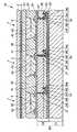
図1は、有機EL素子の一例を示した縦断面図である。なお、以下の説明では、図1中の上側を「上」、下側を「下」と言う。Hereinafter, a method for manufacturing a semiconductor element, a semiconductor element, an electronic device, and an electronic apparatus of the present invention will be described in detail based on preferred embodiments shown in the accompanying drawings.
Hereinafter, a case where the semiconductor element of the present invention is applied to an organic electroluminescence element (hereinafter simply referred to as “organic EL element”) will be described as an example.
<Organic electroluminescence device>
FIG. 1 is a longitudinal sectional view showing an example of an organic EL element. In the following description, the upper side in FIG. 1 is referred to as “upper” and the lower side is referred to as “lower”.
図1に示す有機EL素子1は、第1の基板2と、第1の基板2上に設けられた陽極3と、陽極3上に設けられたEL層4と、EL層4上に設けられた陰極5と、陰極5上に設けられた第2の基板6とを備えている。また、図示しない保護層が各前記層3、4、5の側面を覆うように設けられている。
第1の基板2と第2の基板6とは、有機EL素子1の支持体となるものであり、これら第1の基板2と第2の基板6との間に各前記層が形成されている。
第1の基板2および第2の基板6の構成材料としては、透光性を有し、光学特性が良好(無色透明、着色透明、半透明)な材料を用いるのが好ましい。An organic EL element 1 shown in FIG. 1 is provided on a
The
As the constituent material of the
このような材料としては、例えば、ポリエチレンテレフタレート、ポリエチレンナフタレート、ポリプロピレン、シクロオレフィンポリマー、ポリアミド、ポリエーテルサルフォン、ポリメチルメタクリレート、ポリカーボネート、ポリアリレートのような各種樹脂材料や、各種ガラス材料等が挙げられ、これらのうちの少なくとも1種を用いることができる。
なお、第1の基板2と第2の基板6とは、同一の構成材料により構成されるものであってもよいし、別の構成材料により構成されるものであってもよい。
これらの厚さ(平均)は、特に限定されないが、0.1〜30mm程度であるのが好ましく、0.1〜10mm程度であるのがより好ましい。Examples of such materials include various resin materials such as polyethylene terephthalate, polyethylene naphthalate, polypropylene, cycloolefin polymer, polyamide, polyethersulfone, polymethyl methacrylate, polycarbonate, and polyarylate, and various glass materials. And at least one of these can be used.
In addition, the 1st board |
Although these thickness (average) is not specifically limited, It is preferable that it is about 0.1-30 mm, and it is more preferable that it is about 0.1-10 mm.
なお、有機EL素子1が第1の基板2側から光を取り出す構成(ボトムエミッション型)の場合、第2の基板6および陰極5は、それぞれ、透明性は要求されない。また、有機EL素子1が第2の基板6側から光を取り出す構成(トップエミッション型)の場合、第1の基板2および陽極3は、それぞれ、透明性は要求されない。
そのため有機EL素子1の構成に応じて、第1の基板2および第2の基板6として、アルミナのようなセラミックス材料で構成された基板、ステンレス鋼のような金属基板の表面に酸化膜(絶縁膜)を形成したもの、不透明な樹脂材料により構成された基板のような不透明基板を用いることができる。In the case where the organic EL element 1 is configured to extract light from the
Therefore, depending on the configuration of the organic EL element 1, as the
陽極3(第1の電極)は、EL層4(後述する正孔輸送層41)に正孔を注入する電極である。この陽極3の構成材料(陽極材料)としては、仕事関数が大きく、導電性に優れた材料を用いるのが好ましい。
このような陽極材料としては、例えば、ITO(Indium Tin Oxide)、SnO2、Sb含有SnO2、Al含有ZnO等の酸化物、Au、Pt、Ag、Cuまたはこれらを含む合金等が挙げられ、これらのうちの少なくとも1種を用いることができる。The anode 3 (first electrode) is an electrode that injects holes into the EL layer 4 (a
Examples of such an anode material include ITO (Indium Tin Oxide), SnO2 , Sb-containing SnO2 , oxides such as Al-containing ZnO, Au, Pt, Ag, Cu, or alloys containing these, and the like. At least one of these can be used.
陽極3の厚さ(平均)は、特に限定されないが、10〜200nm程度であるのが好ましく、50〜150nm程度であるのがより好ましい。陽極3の厚さが薄すぎると、陽極3としての機能が充分に発揮されなくなるおそれがあり、一方、陽極3が厚過ぎると、陽極材料の種類等によっては、光の透過率が著しく低下し、有機EL素子1の構成がボトムエミッション型の場合、実用に適さなくなるおそれがある。
なお、陽極材料には、例えば、ポリチオフェン、ポリピロール等の導電性樹脂材料を用いることもできる。The thickness (average) of the
As the anode material, for example, a conductive resin material such as polythiophene or polypyrrole can be used.
一方、陰極5(第2の電極)は、EL層4(後述する電子輸送層43)に電子を注入する電極である。
陰極5の構成材料(陰極材料)としては、仕事関数の小さい材料を用いるのが好ましい。
このような陰極材料としては、Li、Mg、Ca、Sr、La、Ce、Er、Eu、Sc、Y、Yb、Ag、Cu、Al、Cs、Rbまたはこれらを含む合金等が挙げられ、これらのうちの少なくとも1種を用いることができる。On the other hand, the cathode 5 (second electrode) is an electrode that injects electrons into the EL layer 4 (
As a constituent material (cathode material) of the
Examples of such cathode materials include Li, Mg, Ca, Sr, La, Ce, Er, Eu, Sc, Y, Yb, Ag, Cu, Al, Cs, Rb, and alloys containing these, and the like. At least one of them can be used.
特に、陰極材料として合金を用いる場合には、Ag、Al、Cu等の安定な金属元素を含む合金、具体的には、MgAg、AlLi、CuLi等の合金を用いるのが好ましい。かかる合金を陰極材料として用いることにより、陰極5の電子注入効率および安定性の向上を図ることができる。
陰極5の厚さ(平均)は、1nm〜1μm程度であるのが好ましく、100〜400nm程度であるのがより好ましい。陰極5の厚さが薄すぎると、陰極5としての機能が充分に発揮されなくなるおそれがあり、一方、陰極5が厚過ぎると、陰極材料の種類等によっては、光の透過率が著しく低下し、有機EL素子1の構成がトップエミッション型の場合、実用に適さなくなるおそれがある。In particular, when an alloy is used as the cathode material, an alloy containing a stable metal element such as Ag, Al, or Cu, specifically, an alloy such as MgAg, AlLi, or CuLi is preferably used. By using such an alloy as the cathode material, the electron injection efficiency and stability of the
The thickness (average) of the
陽極3(第1の電極)と陰極5(第2の電極)との間には、EL層4が設けられている。EL層4は、正孔輸送層41と、発光層42と、電子輸送層43とを備え、これらが陽極3側からこの順で形成されている。
正孔輸送層41は、陽極3から注入された正孔を発光層42まで輸送する機能を有するものである。An EL layer 4 is provided between the anode 3 (first electrode) and the cathode 5 (second electrode). The EL layer 4 includes a
The
本実施形態では、この正孔輸送層41が、後述する有機EL素子の製造方法において、第1の基板側および第2の基板側にそれぞれ設けられた層41’同士を一体化することにより形成されている。すなわち、第1の基板2側および第2の基板6側に、それぞれ、重合性基Xを有する正孔輸送材料(半導体材料)を主材料として構成される層41’を形成する。そして、これら2つの層41’同士を接触させた状態で、重合性基X同士を重合させる。これにより、正孔輸送材料が高分子化されて、2つの層41’が一体化されることにより、正孔輸送層41が形成される。 In the present embodiment, the
かかる工程を経て正孔輸送層41が形成されることから、2つの層41’が貼り合わされた界面(接合面)付近においても、重合性基X同士が重合して形成された連結構造が存在することとなる。その結果、2つの層41’同士は、連結構造により化学的に連結されたものとなり、正孔輸送層41は、この界面付近において優れた密着性を有するものとなる。これにより、このような正孔輸送層41を備える有機EL素子1は、優れた特性を発揮するものとなる。 Since the
正孔輸送材料(半導体材料)は、正孔輸送能力を有し、正孔輸送材料同士を連結し得る重合性基Xを備えるものであれば、いかなるものであってもよいが、共役系の構造を有する化合物であるのが好ましい。共役系の構造を有する化合物は、その特有な電子雲の広がりによる性質上、極めて円滑に正孔を輸送できるため、正孔輸送能力に特に優れる。
このような正孔輸送材料としては、例えば、3,4−エチレンジオキシチオフェン/スチレンスルホン酸のようなチオフェン/スチレンスルホン酸系化合物、1,1−ビス(4−ジ−パラ−トリアミノフェニル)シクロへキサン、1,1’−ビス(4−ジ−パラ−トリルアミノフェニル)−4−フェニル−シクロヘキサンのようなアリールシクロアルカン系化合物、4,4’,4’’−トリメチルトリフェニルアミン、N,N,N’,N’−テトラフェニル−1,1’−ビフェニル−4,4’−ジアミン、N,N’−ジフェニル−N,N’−ビス(3−メチルフェニル)−1,1’−ビフェニル−4,4’−ジアミン(TPD1)、N,N’−ジフェニル−N,N’−ビス(4−メトキシフェニル)−1,1’−ビフェニル−4,4’−ジアミン(TPD2)、N,N,N’,N’−テトラキス(4−メトキシフェニル)−1,1’−ビフェニル−4,4’−ジアミン(TPD3)、N,N’−ジ(1−ナフチル)−N,N’−ジフェニル−1,1’−ビフェニル−4,4’−ジアミン(α−NPD)、TPTEのようなアリールアミン系化合物、N,N,N’,N’−テトラフェニル−パラ−フェニレンジアミン、N,N,N’,N’−テトラ(パラ−トリル)−パラ−フェニレンジアミン、N,N,N’,N’−テトラ(メタ−トリル)−メタ−フェニレンジアミン(PDA)のようなフェニレンジアミン系化合物、カルバゾール、N−イソプロピルカルバゾール、N−フェニルカルバゾールのようなカルバゾール系化合物、スチルベン、4−ジ−パラ−トリルアミノスチルベンのようなスチルベン系化合物、OxZのようなオキサゾール系化合物、トリフェニルメタンm−MTDATAのようなトリフェニルメタン系化合物、1−フェニル−3−(パラ−ジメチルアミノフェニル)ピラゾリンのようなピラゾリン系化合物、ベンジン(シクロヘキサジエン)系化合物、トリアゾールのようなトリアゾール系化合物、イミダゾールのようなイミダゾール系化合物、1,3,4−オキサジアゾール、2,5−ジ(4−ジメチルアミノフェニル)−1,3,4,−オキサジアゾールのようなオキサジアゾール系化合物、アントラセン、9−(4−ジエチルアミノスチリル)アントラセンのようなアントラセン系化合物、フルオレノン、2,4,7,−トリニトロ−9−フルオレノン、2,7−ビス(2−ヒドロキシ−3−(2−クロロフェニルカルバモイル)−1−ナフチルアゾ)フルオレノンのようなフルオレノン系化合物、ポリアニリンのようなアニリン系化合物、シラン系化合物、ポリチオフェン、ポリ(チオフェンビニレン)のようなチオフェン系化合物、ポリ(2,2’−チエニルピロール)、1,4−ジチオケト−3,6−ジフェニル−ピロロ−(3,4−c)ピロロピロールのようなピロール系化合物、フローレンのようなフローレン系化合物、ポルフィリン、金属テトラフェニルポルフィリンのようなポルフィリン系化合物、キナクリドンのようなキナクリドン系化合物、フタロシアニン、銅フタロシアニン、テトラ(t−ブチル)銅フタロシアニン、鉄フタロシアニンのような金属または無金属のフタロシアニン系化合物、銅ナフタロシアニン、バナジルナフタロシアニン、モノクロロガリウムナフタロシアニンのような金属または無金属のナフタロシアニン系化合物、N,N’−ジ(ナフタレン−1−イル)−N,N’−ジフェニル−ベンジジン、N,N,N’,N’−テトラフェニルベンジジンのようなベンジジン系化合物等に重合性基Xを導入した化合物が挙げられる。これらの化合物の高分子は、いずれも、高い正孔輸送能力を有している。The hole transport material (semiconductor material) may be any material as long as it has a hole transport capability and has a polymerizable group X capable of connecting the hole transport materials to each other. A compound having a structure is preferred. A compound having a conjugated structure is particularly excellent in hole transport capability because it can transport holes very smoothly due to its unique electron cloud spread.
Examples of such hole transporting materials include thiophene / styrene sulfonic acid compounds such as 3,4-ethylenedioxythiophene / styrene sulfonic acid, and 1,1-bis (4-di-para-triaminophenyl). ) Cyclohexane, arylcycloalkane compounds such as 1,1′-bis (4-di-para-tolylaminophenyl) -4-phenyl-cyclohexane, 4,4 ′, 4 ″ -trimethyltriphenylamine N, N, N ′, N′-tetraphenyl-1,1′-biphenyl-4,4′-diamine, N, N′-diphenyl-N, N′-bis (3-methylphenyl) -1, 1′-biphenyl-4,4′-diamine (TPD1), N, N′-diphenyl-N, N′-bis (4-methoxyphenyl) -1,1′-biphenyl-4,4′-diamine (TPD2) ), N, N, N ′, N′-tetrakis (4-methoxyphenyl) -1,1′-biphenyl-4,4′-diamine (TPD3), N, N′-di (1-naphthyl) -N, N′— Diphenyl-1,1′-biphenyl-4,4′-diamine (α-NPD), arylamine compounds such as TPTE, N, N, N ′, N′-tetraphenyl-para-phenylenediamine, N, Phenylenediamines such as N, N ′, N′-tetra (para-tolyl) -para-phenylenediamine, N, N, N ′, N′-tetra (meta-tolyl) -meta-phenylenediamine (PDA) compounds, carbazole, N- isopropyl carbazole, carbazole-based compounds such as N- phenyl carbazole, stilbene, 4-di - para - stilbene compounds such as tolyl aminostilbene, the O xZ Oxazole compounds, triphenylmethane compounds such as triphenylmethane m-MTDATA, pyrazoline compounds such as 1-phenyl-3- (para-dimethylaminophenyl) pyrazoline, benzine (cyclohexadiene) compounds, triazole Such as triazole compounds such as imidazole, imidazole compounds such as imidazole, 1,3,4-oxadiazole, 2,5-di (4-dimethylaminophenyl) -1,3,4, -oxadiazole Oxadiazole compounds, anthracene, anthracene compounds such as 9- (4-diethylaminostyryl) anthracene, fluorenone, 2,4,7, -trinitro-9-fluorenone, 2,7-bis (2-hydroxy-) 3- (2-Chlorophenylcarbamoyl) -1- (Futylazo) fluorenone compounds such as fluorenone, aniline compounds such as polyaniline, silane compounds, polythiophene, thiophene compounds such as poly (thiophene vinylene), poly (2,2′-thienylpyrrole), 1,4 A pyrrole compound such as dithioketo-3,6-diphenyl-pyrrolo- (3,4-c) pyrrolopyrrole, a fluorene compound such as fluorene, a porphyrin, a porphyrin compound such as metal tetraphenylporphyrin, quinacridone Quinacridone compounds such as phthalocyanine, copper phthalocyanine, tetra (t-butyl) copper phthalocyanine, metal or metal-free phthalocyanine compounds such as iron phthalocyanine, copper naphthalocyanine, vanadyl naphthalocyanine, monochloroga Metallic or metal-free naphthalocyanine compounds such as umnaphthalocyanine, N, N′-di (naphthalen-1-yl) -N, N′-diphenyl-benzidine, N, N, N ′, N′-tetra Examples thereof include compounds in which a polymerizable group X is introduced into a benzidine-based compound such as phenylbenzidine. Each of these polymer polymers has a high hole transport capability.
また、重合性基Xとしては、これらのもの同士が重合(連結)し得るものであれば、特に限定されないが、光重合性または熱重合性を有するものであるのが好ましい。
光重合性を有する重合性基Xを用いた場合、光を照射することにより重合性基X同士を容易に重合させることができる。
このような重合性基Xとしては、例えば、(メタ)アクリロイル基、ビニル基、エポキシ基、ジアゾ基およびジチオカルバメート基等の置換基を末端に備えるものが挙げられる。これらの置換基は、特に優れた光重合性を有するものである。Further, the polymerizable group X is not particularly limited as long as these can be polymerized (linked) to each other, but preferably has photopolymerizability or thermal polymerizability.
When the polymerizable group X having photopolymerizability is used, the polymerizable groups X can be easily polymerized by irradiating light.
Examples of such a polymerizable group X include those having a terminal substituent such as a (meth) acryloyl group, a vinyl group, an epoxy group, a diazo group, and a dithiocarbamate group. These substituents have particularly excellent photopolymerizability.
熱重合性を有する重合性基Xを用いた場合、加熱より重合性基X同士を容易に重合させることができる。
このような重合性基Xとしては、例えば、エポキシ基等の置換基を末端に備えるものが挙げられる。これらの置換基は、特に優れた熱重合性を有するものである。
また、正孔輸送材料には、例えば、下記一般式(A1)または下記一般式(A2)で表される化合物のうち、正孔輸送能を有するものを用いることもできる。
これらの化合物については、後で詳述する。When the polymerizable group X having thermal polymerizability is used, the polymerizable groups X can be easily polymerized by heating.
Examples of such a polymerizable group X include those having a substituent such as an epoxy group at the terminal. These substituents have particularly excellent thermal polymerizability.
In addition, as the hole transport material, for example, a compound having a hole transport ability among the compounds represented by the following general formula (A1) or the following general formula (A2) can be used.
These compounds will be described in detail later.
また、このような正孔輸送材料は、その体積抵抗率が10Ω・cm以上であるのが好ましく、102Ω・cm以上であるのがより好ましい。これにより、発光効率のより高い有機EL素子1を得ることができる。
正孔輸送層41の厚さ(平均)は、特に限定されないが、10〜150nm程度であるのが好ましく、50〜100nm程度であるのがより好ましい。正孔輸送層41の厚さが薄すぎると、ピンホールが生じるおそれがあり、一方、正孔輸送層41が厚過ぎると、正孔輸送層41の透過率が悪くなる原因となり、有機EL素子1の発光色の色度(色相)が変化してしまうおそれがある。In addition, such a hole transport material preferably has a volume resistivity of 10 Ω · cm or more, and more preferably 102 Ω · cm or more. Thereby, the organic EL element 1 with higher luminous efficiency can be obtained.
The thickness (average) of the
電子輸送層43は、陰極5から注入された電子を発光層42まで輸送する機能を有するものである。
電子輸送層43の構成材料(電子輸送材料)としては、例えば、1,3,5−トリス[(3−フェニル−6−トリ−フルオロメチル)キノキサリン−2−イル]ベンゼン(TPQ1)、1,3,5−トリス[{3−(4−t−ブチルフェニル)−6−トリスフルオロメチル}キノキサリン−2−イル]ベンゼン(TPQ2)のようなベンゼン系化合物(スターバースト系化合物)、ナフタレンのようなナフタレン系化合物、フェナントレンのようなフェナントレン系化合物、クリセンのようなクリセン系化合物、ペリレンのようなペリレン系化合物、アントラセンのようなアントラセン系化合物、ピレンのようなピレン系化合物、アクリジンのようなアクリジン系化合物、スチルベンのようなスチルベン系化合物、BBOTのようなチオフェン系化合物、ブタジエンのようなブタジエン系化合物、クマリンのようなクマリン系化合物、キノリンのようなキノリン系化合物、ビスチリルのようなビスチリル系化合物、ピラジン、ジスチリルピラジンのようなピラジン系化合物、キノキサリンのようなキノキサリン系化合物、ベンゾキノン、2,5−ジフェニル−パラ−ベンゾキノンのようなベンゾキノン系化合物、ナフトキノンのようなナフトキノン系化合物、アントラキノンのようなアントラキノン系化合物、オキサジアゾール、2−(4−ビフェニリル)−5−(4−t−ブチルフェニル)−1,3,4−オキサジアゾール(PBD)、BMD、BND、BDD、BAPDのようなオキサジアゾール系化合物、トリアゾール、3,4,5−トリフェニル−1,2,4−トリアゾールのようなトリアゾール系化合物、オキサゾール系化合物、アントロンのようなアントロン系化合物、フルオレノン、1,3,8−トリニトロ−フルオレノン(TNF)のようなフルオレノン系化合物、ジフェノキノン、MBDQのようなジフェノキノン系化合物、スチルベンキノン、MBSQのようなスチルベンキノン系化合物、アントラキノジメタン系化合物、チオピランジオキシド系化合物、フルオレニリデンメタン系化合物、ジフェニルジシアノエチレン系化合物、フローレンのようなフローレン系化合物、フタロシアニン、銅フタロシアニン、鉄フタロシアニンのような金属または無金属のフタロシアニン系化合物、(8−ヒドロキシキノリン)アルミニウム(Alq3)、ベンゾオキサゾールやベンゾチアゾールを配位子とする錯体のような各種金属錯体等が挙げられ、これらのうちの少なくとも1種を用いることができる。The
As a constituent material (electron transport material) of the electron transport layer 43, for example, 1,3,5-tris [(3-phenyl-6-tri-fluoromethyl) quinoxalin-2-yl] benzene (TPQ1), 1, Benzene compounds (starburst compounds) such as 3,5-tris [{3- (4-t-butylphenyl) -6-trisfluoromethyl} quinoxalin-2-yl] benzene (TPQ2), such as naphthalene Naphthalene compounds, phenanthrene compounds such as phenanthrene, chrysene compounds such as chrysene, perylene compounds such as perylene, anthracene compounds such as anthracene, pyrene compounds such as pyrene, acridines such as acridine Compounds, stilbene compounds such as stilbene, thiophene such as BBOT Compounds, butadiene compounds such as butadiene, coumarin compounds such as coumarin, quinoline compounds such as quinoline, bistyryl compounds such as bistyryl, pyrazine compounds such as pyrazine and distyrylpyrazine, quinoxaline Quinoxaline compounds, benzoquinone, benzoquinone compounds such as 2,5-diphenyl-para-benzoquinone, naphthoquinone compounds such as naphthoquinone, anthraquinone compounds such as anthraquinone, oxadiazole, 2- (4-biphenylyl) -5- (4-t-butylphenyl) -1,3,4-oxadiazole (PBD), oxadiazole compounds such as BMD, BND, BDD, BAPD, triazole, 3,4,5-tri Phenyl-1,2,4-triazol Triazole compounds such as oxazole compounds, anthrone compounds such as anthrone, fluorenone, fluorenone compounds such as 1,3,8-trinitro-fluorenone (TNF), diphenoquinone, diphenoquinone compounds such as MBDQ, Stilbenequinone, stilbenequinone compounds such as MBSQ, anthraquinodimethane compounds, thiopyran dioxide compounds, fluorenylidenemethane compounds, diphenyldicyanoethylene compounds, fluorene compounds such as fluorene, phthalocyanine, copper phthalocyanine, metal or metal-free phthalocyanine compound such as iron phthalocyanine, (8-hydroxyquinoline) aluminum (Alq3), a a ligand benzoxazole or benzothiazole Various metal complexes, and the like, such as the body, it is possible to use at least one of these.
なお、このような電子輸送材料の他、正孔輸送材料で挙げた上記一般式(A1)または上記一般式(A2)で表される化合物や、これらの化合物同士を重合性基Xにおいて重合させて得られる高分子のうち電子輸送能を発揮するものを電子輸送材料として用いることもできる。
このような化合物については、後で詳述する。In addition to such an electron transport material, the compound represented by the above general formula (A1) or the above general formula (A2) mentioned for the hole transport material, or these compounds are polymerized in the polymerizable group X. Among these polymers, those that exhibit electron transporting ability can be used as an electron transporting material.
Such compounds will be described in detail later.
電子輸送層43の厚さ(平均)は、特に限定されないが、1〜100nm程度であるのが好ましく、20〜50nm程度であるのがより好ましい。電子輸送層43の厚さが薄すぎると、ピンホールが生じショートするおそれがあり、一方、電子輸送層43が厚過ぎると、抵抗値が高くなるおそれがある。
ここで、陽極3と陰極5との間に通電(電圧を印加)すると、陽極3から放出された正孔が正孔輸送層41中を移動するとともに、陰極5から放出された電子が電子輸送層43中を移動し、最終的に、この正孔と電子とが発光層42において再結合する。そして、発光層42では、この再結合に際して放出されたエネルギーによりエキシトン(励起子)が生成し、このエキシトンが基底状態に戻る際にエネルギー(蛍光やりん光)を放出(発光)する。The thickness (average) of the
Here, when an electric current is applied between the
この発光層42の構成材料(発光材料)としては、電圧印加時に陽極3側から正孔を、また、陰極5側から電子を注入することができ、正孔と電子が再結合する場を提供できるものであれば、いかなるものであってもよい。
このような発光材料には、以下に示すような、各種低分子の発光材料、各種高分子の発光材料があり、これらのうちの少なくとも1種を用いることができる。As a constituent material (light emitting material) of the
Such luminescent materials include various low-molecular luminescent materials and various high-molecular luminescent materials as described below, and at least one of them can be used.
なお、低分子の発光材料を用いることにより、緻密な発光層42が得られるため、発光層42の発光効率が向上する。また、高分子の発光材料を用いることにより、比較的容易に溶剤へ溶解させることができるため、インクジェット印刷法等の各種塗布法による発光層42の形成を容易に行うことができる。さらに、低分子の発光材料と高分子の発光材料とを組み合わせて用いることにより、低分子の発光材料および高分子の発光材料を用いる効果を併有すること、すなわち、緻密かつ発光効率に優れる発光層42を、インクジェット印刷法等の各種塗布法により、容易に形成することができるという効果が得られる。 In addition, since the dense
低分子の発光材料としては、例えば、ジスチリルベンゼン(DSB)、ジアミノジスチリルベンゼン(DADSB)のようなベンゼン系化合物、ナフタレン、ナイルレッドのようなナフタレン系化合物、フェナントレンのようなフェナントレン系化合物、クリセン、6−ニトロクリセンのようなクリセン系化合物、ペリレン、N,N’−ビス(2,5−ジ−t−ブチルフェニル)−3,4,9,10−ペリレン−ジ−カルボキシイミド(BPPC)のようなペリレン系化合物、コロネンのようなコロネン系化合物、アントラセン、ビススチリルアントラセンのようなアントラセン系化合物、ピレンのようなピレン系化合物、4−(ジ−シアノメチレン)−2−メチル−6−(パラ−ジメチルアミノスチリル)−4H−ピラン(DCM)のようなピラン系化合物、アクリジンのようなアクリジン系化合物、スチルベンのようなスチルベン系化合物、2,5−ジベンゾオキサゾールチオフェンのようなチオフェン系化合物、ベンゾオキサゾールのようなベンゾオキサゾール系化合物、ベンゾイミダゾールのようなベンゾイミダゾール系化合物、2,2’−(パラ−フェニレンジビニレン)−ビスベンゾチアゾールのようなベンゾチアゾール系化合物、ビスチリル(1,4−ジフェニル−1,3−ブタジエン)、テトラフェニルブタジエンのようなブタジエン系化合物、ナフタルイミドのようなナフタルイミド系化合物、クマリンのようなクマリン系化合物、ペリノンのようなペリノン系化合物、オキサジアゾールのようなオキサジアゾール系化合物、アルダジン系化合物、1,2,3,4,5−ペンタフェニル−1,3−シクロペンタジエン(PPCP)のようなシクロペンタジエン系化合物、キナクリドン、キナクリドンレッドのようなキナクリドン系化合物、ピロロピリジン、チアジアゾロピリジンのようなピリジン系化合物、2,2’,7,7’−テトラフェニル−9,9’−スピロビフルオレンのようなスピロ化合物、フタロシアニン(H2Pc)、銅フタロシアニンのような金属または無金属のフタロシアニン系化合物、フローレンのようなフローレン系化合物、(8−ヒドロキシキノリン)アルミニウム(Alq3)、トリス(4−メチル−8キノリノレート)アルミニウム(III)(Almq3)、(8−ヒドロキシキノリン)亜鉛(Znq2)、(1,10−フェナントロリン)−トリス−(4,4,4−トリフルオロ−1−(2−チエニル)−ブタン−1,3−ジオネート)ユーロピウム(III)(Eu(TTA)3(phen))、ファクトリス(2−フェニルピリジン)イリジウム(Ir(ppy)3)、(2,3,7,8,12,13,17,18−オクタエチル−21H,23H−ポルフィン)プラチナム(II)のような各種金属錯体等が挙げられる。Examples of low-molecular light emitting materials include benzene compounds such as distyrylbenzene (DSB) and diaminodistyrylbenzene (DADSB), naphthalene compounds such as naphthalene and nile red, phenanthrene compounds such as phenanthrene, Chrysene, chrysene compounds such as 6-nitrochrysene, perylene, N, N′-bis (2,5-di-t-butylphenyl) -3,4,9,10-perylene-di-carboximide (BPPC) Perylene compounds such as coronene, anthracene compounds such as anthracene and bisstyrylanthracene, pyrene compounds such as pyrene, 4- (di-cyanomethylene) -2-methyl-6 Such as-(para-dimethylaminostyryl) -4H-pyran (DCM) Pyran compounds, acridine compounds such as acridine, stilbene compounds such as stilbene, thiophene compounds such as 2,5-dibenzoxazole thiophene, benzoxazole compounds such as benzoxazole, benzos such as benzimidazole Imidazole compounds, benzothiazole compounds such as 2,2 ′-(para-phenylenedivinylene) -bisbenzothiazole, bistyryl (1,4-diphenyl-1,3-butadiene), butadienes such as tetraphenylbutadiene Compounds, naphthalimide compounds such as naphthalimide, coumarin compounds such as coumarin, perinone compounds such as perinone, oxadiazole compounds such as oxadiazole, aldazine compounds, 1, 2, 3 , 4, Cyclopentadiene compounds such as 5-pentaphenyl-1,3-cyclopentadiene (PPCP), quinacridone compounds such as quinacridone and quinacridone red, pyridine compounds such as pyrrolopyridine and thiadiazolopyridine, 2,2 Spiro compounds such as', 7,7'-tetraphenyl-9,9'-spirobifluorene, phthalocyanine (H2 Pc), metal or non-metal phthalocyanine compounds such as copper phthalocyanine, florene such as fluorene Compounds, (8-hydroxyquinoline) aluminum (Alq3 ), tris (4-methyl-8quinolinolate) aluminum (III) (Almq3 ), (8-hydroxyquinoline) zinc (Znq2 ), (1,10- Phenanthroline) -tris- (4,4,4-trif Oro-1- (2-thienyl) - butane-1,3-Jioneto) europium(III) (Eu (TTA) 3 (phen)), factory scan (2-phenylpyridine) iridium (Ir(ppy) 3), Various metal complexes such as (2,3,7,8,12,13,17,18-octaethyl-21H, 23H-porphine) platinum (II) can be mentioned.
高分子の発光材料としては、例えば、トランス型ポリアセチレン、シス型ポリアセチレン、ポリ(ジ−フェニルアセチレン)(PDPA)、ポリ(アルキル,フェニルアセチレン)(PAPA)のようなポリアセチレン系化合物、ポリ(パラ−フェンビニレン)(PPV)、ポリ(2,5−ジアルコキシ−パラ−フェニレンビニレン)(RO−PPV)、シアノ−置換−ポリ(パラ−フェンビニレン)(CN−PPV)、ポリ(2−ジメチルオクチルシリル−パラ−フェニレンビニレン)(DMOS−PPV)、ポリ(2−メトキシ,5−(2’−エチルヘキソキシ)−パラ−フェニレンビニレン)(MEH−PPV)のようなポリパラフェニレンビニレン系化合物、ポリ(3−アルキルチオフェン)(PAT)、ポリ(オキシプロピレン)トリオール(POPT)のようなポリチオフェン系化合物、ポリ(9,9−ジアルキルフルオレン)(PDAF)、α,ω−ビス[N,N’−ジ(メチルフェニル)アミノフェニル]−ポリ[9,9−ビス(2−エチルヘキシル)フルオレン−2,7−ジル](PF2/6am4)、ポリ(9,9−ジオクチル−2,7−ジビニレンフルオレニル−オルト−コ(アントラセン−9,10−ジイル)のようなポリフルオレン系化合物、ポリ(パラ−フェニレン)(PPP)、ポリ(1,5−ジアルコキシ−パラ−フェニレン)(RO−PPP)のようなポリパラフェニレン系化合物、ポリ(N−ビニルカルバゾール)(PVK)のようなポリカルバゾール系化合物、ポリ(メチルフェニルシラン)(PMPS)、ポリ(ナフチルフェニルシラン)(PNPS)、ポリ(ビフェニリルフェニルシラン)(PBPS)のようなポリシラン系化合物等が挙げられる。 Examples of the polymer light-emitting material include polyacetylene compounds such as trans-type polyacetylene, cis-type polyacetylene, poly (di-phenylacetylene) (PDPA), poly (alkyl, phenylacetylene) (PAPA), and poly (para-para-). Fenvinylene) (PPV), poly (2,5-dialkoxy-para-phenylenevinylene) (RO-PPV), cyano-substituted-poly (para-phenvinylene) (CN-PPV), poly (2-dimethyloctyl) Polyparaphenylene vinylene compounds such as silyl-para-phenylene vinylene (DMOS-PPV), poly (2-methoxy, 5- (2′-ethylhexoxy) -para-phenylene vinylene) (MEH-PPV), poly ( 3-alkylthiophene) (PAT), poly (oxypropylene) Polythiophene compounds such as riol (POPT), poly (9,9-dialkylfluorene) (PDAF), α, ω-bis [N, N′-di (methylphenyl) aminophenyl] -poly [9,9- Bis (2-ethylhexyl) fluorene-2,7-diyl] (PF2 / 6am4), poly (9,9-dioctyl-2,7-divinylenefluorenyl-ortho-co (anthracene-9,10-diyl) Polyfluorene compounds such as poly (para-phenylene) (PPP), polyparaphenylene compounds such as poly (1,5-dialkoxy-para-phenylene) (RO-PPP), poly (N-vinyl) Polycarbazole compounds such as carbazole (PVK), poly (methylphenylsilane) (PMPS), poly (naphthylphenylsilane) PnPs), polysilane-based compounds such as poly (biphenylyl phenyl silane) (pBPS), and the like.
なお、正孔輸送層41に用いられる正孔輸送材料の種類と、電子輸送層43に用いられる電子輸送材料の種類との組み合わせによっては、上述したような発光材料の他、正孔輸送材料で挙げた上記一般式(A1)または上記一般式(A2)で表される化合物や、これらの化合物同士を重合性基において重合反応させて得られる高分子を発光材料として用いることもできる。
このような化合物については、後で詳述する。Note that depending on the combination of the type of the hole transport material used for the
Such compounds will be described in detail later.
発光層42の厚さ(平均)は、特に限定されないが、10〜150nm程度であるのが好ましく、50〜100nm程度であるのがより好ましい。発光層の厚さを前記範囲とすることにより、正孔と電子との再結合が効率よくなされ、発光層42の発光効率をより向上させることができる。
なお、本実施形態では、発光層42は、正孔輸送層41および電子輸送層43と別個に設けられているが、正孔輸送層41と発光層42とを兼ねた正孔輸送性発光層や、電子輸送層43と発光層42とを兼ねた電子輸送性発光層とすることもできる。この場合、正孔輸送性発光層の電子輸送層43との界面付近が、また、電子輸送性発光層の正孔輸送層41との界面付近が、それぞれ、発光層42として機能する。The thickness (average) of the
In the present embodiment, the
また、正孔輸送性発光層を用いた場合には、陽極から正孔輸送性発光層に注入された正孔が電子輸送層によって閉じこめられ、また、電子輸送性発光層を用いた場合には、陰極から電子輸送性発光層に注入された電子が電子輸送性発光層に閉じこめられるため、いずれも、正孔と電子との再結合効率を向上させることができるという利点がある。
また、各層3、4、5同士の間には、任意の目的の層が設けられていてもよい。例えば、正孔輸送層41と陽極3との間には正孔注入層を、また、電子輸送層43と陰極5との間には電子注入層等を設けることができる。このように、有機EL素子1に正孔注入層を設ける場合には、この正孔注入層に、上述したような正孔輸送材料を用いることもできる。また、有機EL素子1に電子注入層を設ける場合には、この電子注入層には、前述したような電子輸送材料の他、例えばLiFのようなアルカリハライド等を用いることができる。In addition, when a hole transporting light emitting layer is used, holes injected from the anode into the hole transporting light emitting layer are confined by the electron transport layer, and when an electron transporting light emitting layer is used, Since electrons injected from the cathode into the electron-transporting light-emitting layer are confined in the electron-transporting light-emitting layer, both have the advantage that the recombination efficiency between holes and electrons can be improved.
In addition, an arbitrary target layer may be provided between the
保護層(図示せず)は、有機EL素子1を構成する各層3、4、5の側面を覆うように設けられている。この保護層は、有機EL素子1を構成する各層3、4、5を気密的に封止し、酸素や水分を遮断する機能を有する。保護層を設けることにより、有機EL素子1の信頼性の向上や、変質・劣化の防止等の効果が得られる。
保護層の構成材料としては、例えば、Al、Au、Cr、Nb、Ta、Tiまたはこれらを含む合金、酸化シリコン、各種樹脂材料等を挙げることができる。なお、保護層の構成材料として導電性を有する材料を用いる場合には、短絡を防止するために、保護層と各層3、4、5の側面との間には、必要に応じて、絶縁膜を設けるのが好ましい。The protective layer (not shown) is provided so as to cover the side surfaces of the
Examples of the constituent material of the protective layer include Al, Au, Cr, Nb, Ta, Ti or alloys containing these, silicon oxide, and various resin materials. In addition, when using the material which has electroconductivity as a constituent material of a protective layer, in order to prevent a short circuit, between a protective layer and the side surfaces of each
なお、第1の基板2または第2の基板6のうち少なくとも一方が可撓性を有する場合、この可撓性を有する基板により各層3、4、5の側面を覆うようにして封止することにより、第1の基板2および/または第2の基板6に保護層としての機能も発揮させることができる。
この有機EL素子1は、例えばディスプレイ用として用いることができるが、その他にも光源等としても使用可能であり、種々の光学的用途等に用いることが可能である。When at least one of the
The organic EL element 1 can be used, for example, for a display, but can also be used as a light source or the like, and can be used for various optical applications.
また、有機EL素子1をディスプレイに適用する場合、その駆動方式としては、特に限定されず、アクティブマトリックス方式、パッシブマトリックス方式のいずれであってもよい。
このような有機EL素子1は、本発明の半導体素子の製造方法を適用して、例えば、次のようにして製造することができる。Further, when the organic EL element 1 is applied to a display, the driving method is not particularly limited, and either an active matrix method or a passive matrix method may be used.
Such an organic EL element 1 can be manufactured, for example, as follows by applying the method for manufacturing a semiconductor element of the present invention.
図2は、図1に示す有機EL素子の製造方法を説明するための図(縦断面図)である。なお、以下の説明では、図1中の上側を「上」、下側を「下」という。
[1]陽極形成工程
まず、第1の基板2を用意し、この第1の基板2上に陽極3を形成する。
陽極3は、例えば、プラズマCVD、熱CVD、レーザーCVDのような化学蒸着法(CVD)、真空蒸着、スパッタリング、イオンプレーティング等の乾式メッキ法、電解メッキ、浸漬メッキ、無電解メッキ等の湿式メッキ法、溶射法、ゾル・ゲル法、MOD法、金属箔の接合等を用いて形成することができる。FIG. 2 is a view (longitudinal sectional view) for explaining a method of manufacturing the organic EL element shown in FIG. In the following description, the upper side in FIG. 1 is referred to as “upper” and the lower side is referred to as “lower”.
[1] Anode formation step First, the
The
[2]陰極形成工程
次に、第2の基板6を用意し、この第2の基板6上に陰極5を形成する。
陰極5は、例えば、真空蒸着法、スパッタリング法、金属箔の接合等を用いて形成することができる。
[3]電子輸送層形成工程
次に、陰極5上に電子輸送層43を形成する。[2] Cathode Formation Step Next, the
The
[3] Electron Transport Layer Formation Step Next, the
電子輸送層43は、前述したような電子輸送材料を溶媒に溶解または分散媒に分散してなる液状の発光層形成用材料を、陰極5上に塗布法等により供給した後、この発光層形成用材料から溶媒または分散媒を除去することにより形成することができる。
発光層形成用材料の調製に用いる溶媒または分散媒としては、後述する正孔輸送層形成工程[5]で説明するのと同様の溶媒または分散媒を用いることができる。
また、塗布法としても、後述する正孔輸送層形成工程[5]で説明するのと同様の方法を用いることができる。The
As the solvent or dispersion medium used for the preparation of the light emitting layer forming material, the same solvent or dispersion medium as described in the hole transport layer forming step [5] described later can be used.
Also, as a coating method, a method similar to that described in the hole transport layer forming step [5] described later can be used.
[4]発光層形成工程
次に、電子輸送層43上に発光層42を形成する。
発光層42は、例えば、前述した電子輸送層43と同様にして形成することができる。すなわち、発光層42は、前述したような発光材料を用いて、前記電子輸送層形成工程[3]で説明したような方法により形成することができる。[4] Light-Emitting Layer Formation Step Next, the light-emitting
The
[5]正孔輸送層形成工程
次に、前記工程[1]により形成された陽極3を備える第1の基板2と、前記工程[2]〜前記工程[4]により形成された陰極5と電子輸送層43と発光層42とがこの順で積層された第2の基板6とを用いて、陽極3と発光層42との間に正孔輸送層41を形成する。このような、正孔輸送層41は、例えば、次のような工程を経て形成することができる。[5] Hole Transport Layer Formation Step Next, the
[5−1] まず、前述したような正孔輸送材料(半導体材料)を溶媒に溶解または分散媒に分散してなる液状の正孔輸送層形成用材料を用意する。
溶媒または分散媒としては、例えば、硝酸、硫酸、アンモニア、過酸化水素、水、二硫化炭素、四塩化炭素、エチレンカーボネイト等の無機溶媒や、メチルエチルケトン(MEK)、アセトン、ジエチルケトン、メチルイソブチルケトン(MIBK)、メチルイソプロピルケトン(MIPK)、シクロヘキサノン等のケトン系溶媒、メタノール、エタノール、イソプロパノール、エチレングリコール、ジエチレングリコール(DEG)、グリセリン等のアルコール系溶媒、ジエチルエーテル、ジイソプロピルエーテル、1,2−ジメトキシエタン(DME)、1,4−ジオキサン、テトラヒドロフラン(THF)、テトラヒドロピラン(THP)、アニソール、ジエチレングリコールジメチルエーテル(ジグリム)、ジエチレングリコールエチルエーテル(カルビトール)等のエーテル系溶媒、メチルセロソルブ、エチルセロソルブ、フェニルセロソルブ等のセロソルブ系溶媒、ヘキサン、ペンタン、ヘプタン、シクロヘキサン等の脂肪族炭化水素系溶媒、トルエン、キシレン、ベンゼン等の芳香族炭化水素系溶媒、ピリジン、ピラジン、フラン、ピロール、チオフェン、メチルピロリドン等の芳香族複素環化合物系溶媒、N,N−ジメチルホルムアミド(DMF)、N,N−ジメチルアセトアミド(DMA)等のアミド系溶媒、ジクロロメタン、クロロホルム、1,2−ジクロロエタン等のハロゲン化合物系溶媒、酢酸エチル、酢酸メチル、ギ酸エチル等のエステル系溶媒、ジメチルスルホキシド(DMSO)、スルホラン等の硫黄化合物系溶媒、アセトニトリル、プロピオニトリル、アクリロニトリル等のニトリル系溶媒、ギ酸、酢酸、トリクロロ酢酸、トリフルオロ酢酸等の有機酸系溶媒のような各種有機溶媒、または、これらを含む混合溶媒等が挙げられる。[5-1] First, a liquid hole transport layer forming material prepared by dissolving the hole transport material (semiconductor material) as described above in a solvent or dispersing in a dispersion medium is prepared.
Examples of the solvent or dispersion medium include inorganic solvents such as nitric acid, sulfuric acid, ammonia, hydrogen peroxide, water, carbon disulfide, carbon tetrachloride, and ethylene carbonate, methyl ethyl ketone (MEK), acetone, diethyl ketone, and methyl isobutyl ketone. (MIBK), ketone solvents such as methyl isopropyl ketone (MIPK), cyclohexanone, alcohol solvents such as methanol, ethanol, isopropanol, ethylene glycol, diethylene glycol (DEG), glycerin, diethyl ether, diisopropyl ether, 1,2-dimethoxy Ethane (DME), 1,4-dioxane, tetrahydrofuran (THF), tetrahydropyran (THP), anisole, diethylene glycol dimethyl ether (diglyme), diethylene glycol ether Ether solvents such as ruether (carbitol), cellosolv solvents such as methyl cellosolve, ethyl cellosolve, phenyl cellosolve, aliphatic hydrocarbon solvents such as hexane, pentane, heptane and cyclohexane, aromatics such as toluene, xylene and benzene Hydrocarbon solvents, aromatic heterocyclic compounds such as pyridine, pyrazine, furan, pyrrole, thiophene and methylpyrrolidone, amides such as N, N-dimethylformamide (DMF) and N, N-dimethylacetamide (DMA) Solvents, halogen compound solvents such as dichloromethane, chloroform, 1,2-dichloroethane, ester solvents such as ethyl acetate, methyl acetate, ethyl formate, sulfur compound solvents such as dimethyl sulfoxide (DMSO), sulfolane, acetonitrile, propionite Le, nitriles such as acrylonitrile, formic acid, acetic acid, trichloroacetic acid, various organic solvents such as an organic acid solvents such as trifluoroacetic acid, or mixed solvents containing them.
また、正孔輸送層形成用材料には、正孔輸送材料の他、重合開始剤を添加するのが好ましい。これにより、後工程[5−5]において、加熱処理や光照射処理のような処理を施すことにより、重合性基X同士による重合(反応)を促進させて、正孔輸送材料の高分子化を確実に行うことができる。
重合開始剤としては、特に限定されないが、例えば、光カチオン重合開始剤や光ラジカル重合開始剤のような光重合開始剤、熱重合開始剤および嫌気重合開始剤等が挙げられる。In addition to the hole transport material, it is preferable to add a polymerization initiator to the hole transport layer forming material. Thereby, in post-process [5-5], by performing a treatment such as a heat treatment or a light irradiation treatment, polymerization (reaction) between the polymerizable groups X is promoted, and the hole transport material is polymerized. Can be performed reliably.
Although it does not specifically limit as a polymerization initiator, For example, photopolymerization initiators, such as a photocationic polymerization initiator and a radical photopolymerization initiator, a thermal polymerization initiator, an anaerobic polymerization initiator, etc. are mentioned.
熱重合開始剤としては、例えば、アゾビスイソブチロニトリル(AIBN)、過酸化ベンゾイルおよびイソフタル酸ジヒドラジド等を用いることができる。
光カチオン重合開始剤としては、例えば、芳香族スルホニウム塩系、芳香族ヨードニウム塩系、芳香族ジアゾニウム塩系、ピリジウム塩系および芳香族ホスホニウム塩系等のオニウム塩系の光カチオン重合開始剤や、鉄アレーン錯体およびスルホン酸エステル等の非イオン系の光カチオン重合開始剤を用いることができる。As the thermal polymerization initiator, for example, azobisisobutyronitrile (AIBN), benzoyl peroxide, isophthalic acid dihydrazide, and the like can be used.
As the cationic photopolymerization initiator, for example, aromatic sulfonium salt-based, aromatic iodonium salt-based, aromatic diazonium salt-based, onium salt-based photocationic polymerization initiators such as aromatic phosphonium salt-based, Nonionic photocationic polymerization initiators such as iron arene complexes and sulfonic acid esters can be used.
光ラジカル重合開始剤としては、例えば、ベンゾフェノン系、ベンゾイン系、アセトフェノン系、ベンジケタール系、ミヒラーズケトン系、アシルフォスフィンオキサイド系、ケトクマリン系、キサンテン系およびチオキサントン系等の光ラジカル重合開始剤を用いることができる。
さらに、重合開始剤として光重合開始剤を用いる場合には、光重合開始剤に適した増感剤を半導体層形成用材料に添加してもよい。Examples of the photo radical polymerization initiator include photo radical polymerization initiators such as benzophenone, benzoin, acetophenone, benziketal, Michler's ketone, acylphosphine oxide, ketocoumarin, xanthene, and thioxanthone. it can.
Furthermore, when using a photopolymerization initiator as a polymerization initiator, a sensitizer suitable for the photopolymerization initiator may be added to the semiconductor layer forming material.
[5−2] 次に、陽極3上および発光層42上に、それぞれ、重合性基Xを有する正孔輸送材料を主材料として構成される層41’を形成する(第1の工程)。
この2つの層41’の厚さを調節することにより、形成される正孔輸送層41の厚さを制御することができる。
このような層41’は、各種の方法を用いて形成することができるが、特に、次のような液相プロセスにより形成するのが好ましい。[5-2] Next, on the
By adjusting the thicknesses of the two
Such a
すなわち、1:陽極3上および発光層42上に、正孔輸送層形成用材料を液相プロセスにより供給して、液状被膜(塗膜)を形成する。2:液状被膜から溶媒または分散媒を除去して、正孔輸送材料を主材料として構成される層41’を形成するのが特に好ましい。これにより、正孔輸送材料が備える重合性基X同士が反応したり、重合性基Xが分解するのを好適に防止して、層41’を形成することができる。 That is, 1: A hole transport layer forming material is supplied on the
液相プロセスとしては、スピンコート法、キャスティング法、マイクログラビアコート法、グラビアコート法、バーコート法、ロールコート法、ワイヤーバーコート法、ディップコート法、スプレーコート法、スクリーン印刷法、フレキソ印刷法、オフセット印刷法、インクジェット印刷法等の各種塗布法を用いることができる。かかる塗布法によれば、正孔輸送層形成用材料を比較的容易に陽極3および発光層42上に供給して、液状被膜を形成することができる。
また、溶媒または分散媒を除去する方法としては、特に限定されず、例えば、自然乾燥の他、加熱による方法、真空(減圧)乾燥、不活性ガスを吹き付ける方法のように強制的に除去するものであってもよい。Liquid phase processes include spin coating, casting, micro gravure coating, gravure coating, bar coating, roll coating, wire bar coating, dip coating, spray coating, screen printing, flexographic printing. Various coating methods such as an offset printing method and an ink jet printing method can be used. According to this coating method, the liquid film can be formed by supplying the hole transport layer forming material onto the
Further, the method for removing the solvent or the dispersion medium is not particularly limited. For example, in addition to natural drying, forcible removal such as heating, vacuum (reduced pressure) drying, or inert gas blowing. It may be.
[5−3] 次に、陽極3上および発光層42上に形成された層41’中に含まれる正孔輸送材料を、形成される正孔輸送層41に含まれる正孔輸送材料の高分子の重合度よりも低い重合度まで重合させる。
これにより、それぞれの層41’を確実に半固形状または固形状のものとすることができる。その結果、次工程[5−4]において、これらの層41’同士を対向させる際に、これらの層41’の一部が陽極3上または発光層42上から流れ落ちるのを好適に防止しつつ、これらの層41’同士の位置決めをより容易に行うことができる。[5-3] Next, the hole transport material contained in the
Thereby, each layer 41 'can be reliably made semi-solid or solid. As a result, in the next step [5-4], when these
さらに、層41’を半固形状または固形状のものとすることにより、層41’の形状の安定性を向上させることができる。その結果、後工程[5−5]において、2つの層41’同士を接触させる際に、層41’の厚さを安定に保つことができる。すなわち、層41’の厚さにバラツキが生じるのを確実に防止することができる。その結果、均一な厚さの正孔輸送層41を形成することができる。これにより、正孔輸送層41の厚さ方向に対する正孔の移動距離がほぼ等しくなり、陽極3からほぼ同時に注入された正孔同士を発光層42との接触面にまでほぼ同時に到達させることができる。その結果、得られる有機EL素子1において、色ムラが生じるのを確実に防止することができる。
なお、形成される正孔輸送層41の重合度よりも低い重合度まで正孔輸送材料を重合させる条件は、後工程[5−5]で正孔輸送材料を高分子化させる条件よりも、緩和な条件に設定すればよい。Furthermore, by making the
In addition, the conditions for polymerizing the hole transport material to a polymerization degree lower than the polymerization degree of the
また、本工程は、陽極3上または発光層42上に形成された層41’のいずれか一方に施すようにしてもよい。すなわち、次工程[5−4]において、これらの層41’同士を対向させる際に、この層41’を鉛直下方に向けた状態とする側のもの(本実施形態においては、第2の基板6側(発光層42上)に設けられた層41’)に、本工程を施すようにすればよい。
なお、前記工程[5−2]おいて溶媒または分散媒を除去することにより、得られる層41’が半固形状または固形状である場合には、本工程を省略するようにしてもよい。Further, this step may be performed on any one of the
In addition, when the
[5−4] 次に、図2(a)に示すように、第2の基板6側に設けられた層41’を鉛直下方に向けた状態とすることにより、発光層42上に設けられた層41’と陽極3上に設けられた層41’とを対向させる。
[5−5] 次に、図2(b)に示すように、発光層42上に設けられた層41’と陽極3上に設けられた層41’とを位置決めしつつ、これらの層41’同士を接触させる。そして、この状態で、重合性基X同士を重合させることにより、正孔輸送材料を高分子化させる。これにより、接触面付近の正孔輸送材料が高分子化して、図2(c)に示すように2つの層41’が一体化されることにより、正孔輸送層41が形成される(第2の工程)。[5-4] Next, as shown in FIG. 2A, the
[5-5] Next, as shown in FIG. 2 (b), the
ここで、形成された正孔輸送層41は、その接着面(接合面)において、重合性基X同士が重合して形成された連結構造により化学的に連結されていることから、優れた密着性を発揮するものとなる。これにより、正孔輸送層41は、優れた正孔輸送能を有するものとなる。
また、層41’中に含まれる正孔輸送材料の重合度は、形成される正孔輸送層41中に含まれる正孔輸送材料の高分子の重合度よりも低くなっている。そのため、層41’中には未反応の重合性基Xが存在(残存)していることから、接触面付近の重合性基X同士が重合するのとほぼ同時に、層41’中の重合性基X同士も重合することとなる。その結果、2つの層41’の接触面と層41’中とにおいて、ほぼ同時に正孔輸送材料が高分子化されることとなる。そのため、形成された正孔輸送層41中の各部において、高分子は、均一に存在することとなる。その結果、2つの層41’同士の接触面は、正孔輸送層41において、ほぼ認識し得ないものとなる。これにより、正孔輸送層41の各部において、正孔輸送能にバラツキが生じるのを好適に抑制または防止することができる。Here, since the formed
Further, the polymerization degree of the hole transport material contained in the
さらに、本発明の半導体装置の製造方法によれば、この層41中に樹脂バインダのような不純物を混入させることなく正孔輸送層41を得ることができることから、正孔輸送層41の正孔輸送能が低減するのを確実に防止することができる。
なお、2つの層41’同士を接触させる際には、必要に応じて第1の基板2に向かって第2の基板6を押圧するようにしてもよい。これにより、重合性基X同士を重合させる際に、それぞれの層41’の表面付近に存在する重合性基X同士をより確実に重合させ得ることから、2つの層41’をより確実に一体化させることができる。Furthermore, according to the method for manufacturing a semiconductor device of the present invention, since the
When the two
また、重合性基X同士を重合させる方法としては、各種の方法が用いられ、例えば、光照射する方法、加熱処理法、および嫌気処理法等が挙げられ、これらの中でも、加熱処理法を用いるのが好ましい。これにより、層41’の全体に亘って、より均一に処理を施すことができることから、正孔輸送層41中の各部における正孔輸送能にムラが生じることを好適に防止することができる。 Moreover, as a method of polymerizing the polymerizable groups X, various methods are used, and examples thereof include a light irradiation method, a heat treatment method, and an anaerobic treatment method. Among these, the heat treatment method is used. Is preferred. Thereby, since it can process more uniformly over the whole layer 41 ', it can prevent suitably that a hole transport ability in each part in the
加熱処理法を用いる場合、加熱温度は、重合性基X同士が重合し得る温度に設定すればよく、特に限定されるものではないが、正孔輸送層41と異なる層、すなわち本実施形態においては、発光層42と電子輸送層43とを構成する主材料のガラス転移温度よりも低く設定されているのが特に好ましい。その結果、加熱処理を施す際に、発光層42や電子輸送層43が溶融するのを確実に防止することができる。これにより、加熱処理の後、除熱する際に、これらの発光層42や電子輸送層43を構成する主材料が結晶化して、これらの層42、43の特性が低減するのを確実に防止することができる。 When the heat treatment method is used, the heating temperature may be set to a temperature at which the polymerizable groups X can be polymerized, and is not particularly limited. However, in the present embodiment, a layer different from the
具体的には、加熱温度は、50〜200℃程度であるのが好ましく、70〜150℃程度であるのがより好ましい。
加熱時間は、5〜90分程度であるのが好ましく、5〜60分程度であるのがより好ましい。
なお、光を照射する方法を用いる場合、層41’に光照射する光としては、例えば、赤外線、可視光線、紫外線およびX線等が挙げられ、これらのうちの1種または2種以上を組み合わせて用いることができる。これらの中でも、紫外線を用いるのが特に好ましい。これにより、重合性基X同士の重合反応を容易かつ確実に進行させることができる。Specifically, the heating temperature is preferably about 50 to 200 ° C, and more preferably about 70 to 150 ° C.
The heating time is preferably about 5 to 90 minutes, and more preferably about 5 to 60 minutes.
In addition, when using the method of irradiating light, as light which irradiates light to layer 41 ', an infrared ray, visible light, an ultraviolet-ray, an X-ray etc. are mentioned, for example, These 1 type or 2 types or more are combined. Can be used. Among these, it is particularly preferable to use ultraviolet rays. Thereby, the polymerization reaction between the polymerizable groups X can easily and reliably proceed.
光照射する紫外線の波長は、200〜420nm程度であるのが好ましく、250〜400nm程度であるのがより好ましい。
また、紫外線の照射強度は、10〜5000mW/cm2程度であるのが好ましく、20〜1000mW/cm2程度であるのがより好ましい。
さらに、紫外線の照射時間は、5〜300秒程度であるのが好ましく、10〜150秒程度であるのがより好ましい。
紫外線の波長、照射強度および照射時間をかかる範囲にすることにより、層41’中に含まれる、正孔輸送材料の高分子化を比較的容易に制御することができる。The wavelength of the ultraviolet rays to be irradiated is preferably about 200 to 420 nm, and more preferably about 250 to 400 nm.
The irradiation intensity of ultraviolet light is preferably in the range of about 10~5000mW / cm2, more preferably about 20 to 1000 mW / cm2.
Furthermore, the ultraviolet irradiation time is preferably about 5 to 300 seconds, and more preferably about 10 to 150 seconds.
By setting the ultraviolet wavelength, irradiation intensity, and irradiation time in such ranges, the polymerization of the hole transport material contained in the
[6]保護層形成工程
次に、陽極3、EL層4および陰極5の側面、すなわち、第1の基板2と第2の基板6との間から露出している部分を覆うように、保護層を形成する。
保護層は、例えば、前述したような材料またはその前駆体を含有する液状材料を、前述した塗布法等により保護層を形成する領域に供給した後、乾燥させることにより形成する(設ける)ことができる。
以上のような工程を経て、有機EL素子1が製造される。[6] Protection Layer Formation Step Next, protection is performed so as to cover the side surfaces of the
The protective layer may be formed (provided) by, for example, supplying a liquid material containing the above-described material or a precursor thereof to a region where the protective layer is to be formed by the above-described coating method or the like and then drying. it can.
The organic EL element 1 is manufactured through the above processes.
なお、本実施形態では、2つの層41’を一体化させることにより正孔輸送層41を形成する場合について説明したが、例えば、2つの層を一体化させて形成する層は、発光層42や電子輸送層43であってもよい。
ここで、2つの層を一体化させて発光層42を形成する場合、前述した発光材料に置換基Xを導入した化合物や、前記一般式(A1)または前記一般式(A2)で表される化合物のうち、発光材料としてなり得るものを用いて、前記正孔輸送層形成工程[5]で説明したような方法により行うことができる。
また、2つの層を一体化させて電子輸送層43を形成する場合、前述した電子輸送材料に置換基Xを導入した化合物や、前記一般式(A1)または前記一般式(A2)で表される化合物のうち、電子輸送能を有するものを用いて、前記正孔輸送層形成工程[5]で説明したような方法により行うことができる。In the present embodiment, the case where the
Here, when the
In addition, when the
<一般式(A1)または一般式(A2)で表される化合物>
次に、正孔輸送材料、発光材料および電子輸送材料で説明した下記一般式(A1)で表される化合物(以下、単に「化合物(A1)」という。)と下記一般式(A2)で表される化合物(以下、単に「化合物(A2)」という。)とについて詳述する。<Compound represented by formula (A1) or formula (A2)>
Next, the compound represented by the following general formula (A1) described in the hole transport material, the light emitting material, and the electron transport material (hereinafter simply referred to as “compound (A1)”) and the following general formula (A2) And the compound (hereinafter simply referred to as “compound (A2)”).
ここで、化合物(A1)において、重合性基Xは、置換基X1を表し、化合物(A2)において、重合性基Xは、置換基X2、置換基X3、置換基X4および置換基X5(以下、これらのものを総称して「置換基X2〜5」ということもある。)を表す。
化合物(A1)および化合物(A2)が重合性基Xとして、以上のようなものを有することから、2つの層を一体化させて半導体層を得る際に、これらの層に含まれる半導体材料として、化合物(A1)および化合物(A2)を用いることができる。Here, in the compound (A1), the polymerizable group X is a substituentX 1, in the compound (A2), the polymerizable group X is a substituted groupX 2, substituentsX 3, substituentsX 4 and substituted Group X5 (hereinafter, these may be collectively referred to as “substituent X2-5 ”).
Since the compound (A1) and the compound (A2) have the polymerizable group X as described above, when a semiconductor layer is obtained by integrating two layers, as a semiconductor material contained in these layers, Compound (A1) and compound (A2) can be used.
また、化合物(A1)および化合物(A2)は、それぞれが備える重合性基Xにおいて重合していない状態でも優れたキャリア輸送能を発揮するが、それぞれの化合物同士を重合性基Xにおいて重合させた高分子は、より優れたキャリア輸送能を発揮するものとなる。
そのため、化合物(A1)または化合物(A2)を重合させた高分子を半導体層の主材料として用いることにより、半導体層は、より優れたキャリア輸送能を発揮するものとなる。
以下、これらの高分子の特徴について説明する。In addition, the compound (A1) and the compound (A2) exhibit excellent carrier transport ability even when they are not polymerized in the polymerizable group X included in each, but each compound is polymerized in the polymerizable group X. The polymer exhibits better carrier transport ability.
Therefore, by using a polymer obtained by polymerizing the compound (A1) or the compound (A2) as the main material of the semiconductor layer, the semiconductor layer exhibits more excellent carrier transport ability.
Hereinafter, the characteristics of these polymers will be described.
これらの高分子(ポリマー)は、化合物(A1)または化合物(A2)(ジフェニルアミン誘導体)同士を、それぞれが有する重合性基Xにおいて重合反応させて得られたもの、すなわち、重合性基以外の主骨格(ジフェニルアミン骨格)同士を、重合性基を反応させて得られた化学構造(以下、この化学構造を「連結構造」という。)により連結してなるものである。 These polymers (polymers) are obtained by polymerizing compounds (A1) or compounds (A2) (diphenylamine derivatives) with each other in a polymerizable group X, that is, a polymer other than a polymerizable group. The skeletons (diphenylamine skeletons) are connected by a chemical structure obtained by reacting a polymerizable group (hereinafter, this chemical structure is referred to as “linked structure”).
まず、化合物(A1)により得られた高分子について説明する。
ここで、化合物(A1)同士を、置換基X1において重合反応させて得られた高分子では、連結構造を介して前記主骨格が繰り返して結合する構成、すなわち、主骨格が所定の距離を離間して繰り返し存在している構成となっていることから、隣接する主骨格同士の相互作用が低減する。First, the polymer obtained from the compound (A1) will be described.
Here, in the polymer obtained by polymerizing the compounds (A1) with each other at the substituent X1 , the main skeleton is repeatedly bonded via the connecting structure, that is, the main skeleton has a predetermined distance. Since it is the structure which is spaced apart and repeatedly exists, the interaction between adjacent main skeletons is reduced.
また、前記主骨格は、共役系の化学構造を有し、その特有な電子雲の広がりにより、高分子における円滑なキャリア輸送に寄与する。
このようなことから、この高分子は、優れたキャリア輸送能を発揮し、かかる高分子を主材料として得られた半導体層は、キャリア輸送能に優れたものとなる。
なお、このような高分子において、主骨格同士の離間距離が短くなり過ぎると、隣接する主骨格同士の相互作用が大きくなる傾向を示し、主骨格の離間距離が長くなり過ぎると、主骨格同士間におけるキャリアの受け渡しが困難となり、高分子のキャリア輸送能が低減する傾向を示す。Further, the main skeleton has a conjugated chemical structure, and contributes to smooth carrier transport in the polymer due to its unique electron cloud spread.
For this reason, this polymer exhibits an excellent carrier transport ability, and a semiconductor layer obtained using such a polymer as a main material has an excellent carrier transport ability.
In such a polymer, if the distance between the main skeletons becomes too short, the interaction between adjacent main skeletons tends to increase, and if the distance between the main skeletons becomes too long, the main skeletons It is difficult to deliver carriers between the two, and the carrier transport ability of the polymer tends to decrease.
かかる観点から、置換基X1の構造を設定するのが好ましく、置換基X1として上記一般式(B1)または(B2)のものを選択した場合には、n1が2〜8、特に3〜6の直鎖状の炭素−炭素結合のものが好ましく、上記一般式(B3)のものを選択した場合には、n2が3〜8、および、mが0〜3の直鎖状の炭素−炭素結合のものが好ましく、特にn2が4〜6、および、mが1または2の直鎖状の炭素−炭素結合のものが好ましい。
かかる関係を満足するより、主骨格同士の距離を適度に保つことが可能となり、高分子中において、隣接する主骨格同士の相互作用をより確実に低減することができるとともに、主骨格同士間におけるキャリアの受け渡しがより確実に行われることから、高分子のキャリア輸送能が優れたものとなる。From this viewpoint, it is preferable to set the configuration of the substituentsX 1, if you select the ones of the general formula (B1) or (B2) as the substituentX 1 is,n 1 is 2-8, especially 3 To 6 linear carbon-carbon bonds are preferred, and when the above general formula (B3) is selected, n2 is 3 to 8 and m is 0 to 3 A carbon-carbon bond is preferable, and a straight-chain carbon-carbon bond in which n2 is 4 to 6 and m is 1 or 2 is particularly preferable.
Rather than satisfying this relationship, it becomes possible to keep the distance between the main skeletons moderately, and in the polymer, the interaction between adjacent main skeletons can be more reliably reduced, and between the main skeletons Since delivery of the carrier is more reliably performed, the carrier transport ability of the polymer is excellent.
ここで、置換基X1として(B1)および(B2)のものを選択した場合には、その末端に、それぞれ、(メタ)アクリロイル基およびエポキシ基が存在する。(メタ)アクリロイル基およびエポキシ基は、高い反応性および結合安定性を有することから、比較的容易に置換基X同士を重合反応させて、鎖長の長い高分子を形成することができる。
さらに、(メタ)アクリロイル基を用いて重合反応させることにより生じた連結構造中には、酸素原子と炭素原子との内に二重結合(π結合)が2つ存在することとなる。これにより、主骨格同士の距離が比較的長くなった場合においても、この2つのπ結合(共役系の結合)を介して、主骨格同士間におけるキャリアの受け渡しを確実に行うことができる。Here, if the selected ones as the substituent X1 (B1) and (B2) is at its end, respectively, there are (meth) acryloyl group and an epoxy group. Since the (meth) acryloyl group and the epoxy group have high reactivity and bond stability, the substituents X can be polymerized relatively easily to form a polymer having a long chain length.
Furthermore, two double bonds (π bonds) exist between the oxygen atom and the carbon atom in the linked structure produced by the polymerization reaction using the (meth) acryloyl group. Thereby, even when the distance between the main skeletons is relatively long, the carrier can be reliably transferred between the main skeletons via the two π bonds (conjugated bonds).
また、2つのπ結合と主骨格との間には直鎖状の炭素−炭素結合(アルキレン基)が存在することから、主骨格同士の相互作用の増強を防止することができる。
また、エポキシ基を用いて重合反応させることにより生じた連結構造中には、エーテル結合と、直鎖状の炭素−炭素結合(アルキレン基)とが存在することとなる。このような構造を有する連結構造中においては、電子の移動が抑制されることとなる。これにより、主骨格同士の距離が比較的短くなった場合においても、主骨格同士の相互作用が増強するのを防止または抑制することができる。In addition, since a linear carbon-carbon bond (alkylene group) exists between the two π bonds and the main skeleton, enhancement of the interaction between the main skeletons can be prevented.
In addition, an ether bond and a linear carbon-carbon bond (alkylene group) are present in the linked structure generated by the polymerization reaction using the epoxy group. In the connection structure having such a structure, the movement of electrons is suppressed. Thereby, even when the distance between the main skeletons becomes relatively short, it is possible to prevent or suppress the interaction between the main skeletons from increasing.
なお、例えば、ベンゼン環のように、π結合の中でも共役系の結合が多い構造が存在すると、この構造を介して隣接する主骨格同士が相互作用を及ぼすようになり、主骨格同士を離間することによる効果が相殺されてしまう。
ところで、置換基X1として(B3)のものを選択した場合には、置換基X1が、上記一般式(B3)に示すように、その末端に官能基として、スチレン基に置換基Zを導入したスチレン誘導体基を有していることから、連結構造中には、ベンゼン環が存在することとなる。For example, when there is a structure having many conjugated bonds among π bonds such as a benzene ring, adjacent main skeletons interact with each other through this structure, and the main skeletons are separated from each other. The effect by this will be offset.
However, if you select ones (B3) as a substituent X1 is a substituted group X1 is, as shown in the above general formula (B3), as a functional group at its terminus, the substituent Z in the styrene groups Since it has an introduced styrene derivative group, a benzene ring is present in the linked structure.
そのため、ベンゼン環と共役系の化学構造を有する主骨格とが接近しすぎる場合、例えば、ベンゼン環と主骨格とがエーテル結合により結合している場合や、n2とmとの合計数が2の場合等では、このベンゼン環を介して隣接する主骨格同士が相互作用を及ぼすようになる。
ところが、この高分子では、主骨格とこのベンゼン環との結合がn2とmとの合計数が3以上、すなわち3つ以上のメチレン基とエーテル結合とを介して形成される。これにより、主骨格とベンゼン環との離間距離が好適な状態に保たれることとなる。その結果、隣接する主骨格同士が相互作用を及ぼしあうのを好適に抑制または防止にすることができる。Therefore, when the benzene ring and the main skeleton having a conjugated chemical structure are too close, for example, when the benzene ring and the main skeleton are bonded by an ether bond, or the total number of n2 and m is 2 In this case, the adjacent main skeletons interact through the benzene ring.
However, in this polymer, the bond between the main skeleton and the benzene ring is formed through a total number of n2 and m of 3 or more, that is, 3 or more methylene groups and an ether bond. As a result, the distance between the main skeleton and the benzene ring is maintained in a suitable state. As a result, it is possible to suitably suppress or prevent the adjacent main skeletons from interacting with each other.
また、置換基Z2は、水素原子、メチル基またはエチル基であるが、置換基Z2は、n2とmとの合計数、すなわちメチレン基の合計数に応じて選択するようにすればよい。
例えば、前記合計数が小さい場合には、置換基Z2としては、メチル基もしくはエチル基を選択するようにすればよい。ここで、メチル基とエチル基が電子供与性の置換基であることから、置換基Z2として、メチル基およびエチル基を選択することにより、電子を主骨格側に偏らせることができる。その結果、ベンゼン環を介して隣接する主骨格同士が相互作用を及ぼすようになるのを好適に防止することができる。The substituent Z2 is a hydrogen atom, a methyl group or an ethyl group, and the substituent Z2 is selected according to the total number of n2 and m, that is, the total number of methylene groups. Good.
For example, wherein when the total number is small, the substituent Z2, it is sufficient to select a methyl or ethyl group. Here, since the methyl group and an ethyl group is an electron donating substituent, as the substituent Z2, by selecting the methyl and ethyl groups, it is possible to bias the electrons in the main skeleton side. As a result, it is possible to suitably prevent the adjacent main skeletons from interacting with each other via the benzene ring.
また、2つの置換基X1は、ほぼ同一の炭素数のものであるのが好ましく、同一の炭素数のものであるのがより好ましい。これにより、隣接する主骨格同士の離間距離をほぼ一定とすることができる。その結果、この高分子中において電子密度に偏りが生じるのを好適に防止することができる。これにより、高分子のキャリア輸送能を向上させることができる。
また、置換基X1は、ベンゼン環の2位から6位のいかなる位置に結合してもよいが、特に、3位、4位または5位のうちのいずれかに結合しているのが好ましい。これにより、隣接する主骨格同士の結合を置換基X1を介して行うことの効果をより顕著に発揮させることができる。すなわち、隣接する主骨格同士をより確実に離間させることができる。Further, the two substituents X1 preferably have substantially the same carbon number, and more preferably have the same carbon number. Thereby, the separation distance between adjacent main skeletons can be made substantially constant. As a result, it is possible to preferably prevent the electron density from being biased in the polymer. Thereby, the carrier transport ability of the polymer can be improved.
The substituent X1 may be bonded to any position from the 2-position to the 6-position of the benzene ring, but is particularly preferably bonded to any one of the 3-position, 4-position or 5-position. . This makes it possible to conspicuously exhibit the effect of performing linking the adjacent main skeletons via the substituents X1. That is, the adjacent main skeletons can be separated more reliably.
次に、置換基R1は、炭素数2〜8の直鎖アルキル基であるが、特に、炭素数3〜6の直鎖アルキル基であるのが好ましい。その結果、この置換基R1による立体障害により、隣接する高分子同士が接近しすぎるのを阻止して、これらの距離を適度に保つことができる。その結果、形成される半導体層において、異なる高分子が有する主骨格同士の間での相互作用を確実に低減することができ、半導体層のキャリア輸送能を優れたものにすることができる。Next, the substituent R1 is a linear alkyl group having 2 to 8 carbon atoms, and particularly preferably a linear alkyl group having 3 to 6 carbon atoms. As a result, the steric hindrance caused by the substituent R1 can prevent adjacent polymers from being too close to each other, and can keep these distances appropriately. As a result, in the formed semiconductor layer, the interaction between main skeletons of different polymers can be reliably reduced, and the carrier transport ability of the semiconductor layer can be improved.
また、2つの置換基R1は、ほぼ同一の炭素数のものであるのが好ましく、同一の炭素数のものであるのがより好ましい。これにより、形成される半導体層において、隣接する高分子同士の距離をほぼ一定の間隔に保つことができる。その結果、半導体層中の高分子の密度が一定なものとなる。
また、置換基R1は、ベンゼン環の2位から6位のいかなる位置に結合してもよいが、特に、4位に結合しているのが好ましい。これにより、置換基R1を導入することの効果をより顕著に発揮させることができる。すなわち、隣接する高分子同士が接近しすぎるのをより確実に阻止することができる。The two substituents R1 preferably have substantially the same carbon number, and more preferably have the same carbon number. Thereby, in the formed semiconductor layer, the distance between adjacent polymers can be maintained at a substantially constant interval. As a result, the density of the polymer in the semiconductor layer becomes constant.
In addition, the substituent R1 may be bonded to any position from the 2nd to 6th positions of the benzene ring, but is particularly preferably bonded to the 4th position. This makes it possible to conspicuously exhibit the effect of introducing a substituent R1. That is, it is possible to more reliably prevent adjacent polymers from being too close to each other.
さらに、置換基R2は、水素原子、メチル基またはエチル基であり、置換基R2は、置換基R1の炭素数に応じて選択するようにすればよい。すなわち、置換基R1の炭素数が大きい場合には、置換基R2としては、水素原子を選択し、置換基R1の炭素数が小さい場合には、置換基R2としては、メチル基もしくはエチル基を選択するようにすればよい。Further, the substituent R2 is a hydrogen atom, a methyl group or an ethyl group, and the substituent R2 may be selected according to the number of carbon atoms of the substituent R1 . That is, when a large number of carbon atoms of the substituents R1, as the substituent R2, a hydrogen atom is selected, when the number of carbon atoms of the substituents R1 is small, the substituent R2, a methyl group Alternatively, an ethyl group may be selected.
ここで、この化合物(A1)において、基(結合基)Yの化学構造を適宜設定することにより、高分子のキャリア輸送能の特性を変化させることができる。
これは、キャリア輸送に寄与する主骨格における電子雲の広がり(電子の分布状態)が変化することに伴って、高分子において、例えば、その価電子帯および伝導帯のエネルギー準位やバンドギャップ(禁止帯幅)の大きさ等が変化することに起因すると考えられる。Here, in this compound (A1), by appropriately setting the chemical structure of the group (bonding group) Y, the characteristics of the carrier transport ability of the polymer can be changed.
This is because, in the polymer, for example, the energy levels and band gaps of the valence band and the conduction band (the band gap (electron distribution state) of the main skeleton that contributes to carrier transport change. This is thought to be due to the change in the size of the forbidden band.
化合物(A1)では、基Yに置換もしくは無置換の芳香族炭化水素環、または、置換もしくは無置換の複素環が少なくとも1つ含まれており、これらの芳香族炭化水素環および/または複素環の種類を適宜選択することにより、高分子におけるキャリア輸送能の特性を比較的容易に調整することができる。
例えば、基(結合基)Yとして、置換もしくは無置換の芳香族炭化水素環により構成されるものを選択することにより、得られる高分子が優れた正孔輸送能を発揮するものとなることから、このような基Yを有する化合物(A1)を前述した正孔輸送材料として用いることができる。
具体的には、無置換の芳香族炭化水素環により構成される構造としては、例えば、下記化学式(C1)〜(C17)で表されるものが挙げられる。In the compound (A1), the group Y contains at least one substituted or unsubstituted aromatic hydrocarbon ring or substituted or unsubstituted heterocyclic ring, and these aromatic hydrocarbon ring and / or heterocyclic ring By appropriately selecting the type, the characteristics of the carrier transport ability in the polymer can be adjusted relatively easily.
For example, by selecting a group composed of a substituted or unsubstituted aromatic hydrocarbon ring as the group (bonding group) Y, the resulting polymer will exhibit excellent hole transport ability. The compound (A1) having such a group Y can be used as the hole transport material described above.
Specifically, examples of the structure constituted by an unsubstituted aromatic hydrocarbon ring include those represented by the following chemical formulas (C1) to (C17).
また、基Yの総炭素数は、6〜30であるのが好ましく、10〜25であるのがより好ましく、10〜20であるのがさらに好ましい。
さらに、基Yにおいて、芳香族炭化水素環の数は、1〜5であるのが好ましく、2〜5であるのがより好ましく、2または3であるのがさらに好ましい。
これらのことを考慮すると、化合物(A1)において、基Yとしては、前記化学式(C1)で表されるビフェニレン基またはその誘導体が特に好ましい構造である。
かかる基を選択することにより、高分子の正孔輸送能がより優れたものとなり、形成される半導体層は、正孔輸送能により優れたものとなる。Further, the total number of carbon atoms of the group Y is preferably 6-30, more preferably 10-25, and even more preferably 10-20.
Further, in the group Y, the number of aromatic hydrocarbon rings is preferably 1 to 5, more preferably 2 to 5, and even more preferably 2 or 3.
In consideration of these, in the compound (A1), as the group Y, a biphenylene group represented by the chemical formula (C1) or a derivative thereof is a particularly preferable structure.
By selecting such a group, the hole transport ability of the polymer becomes more excellent, and the formed semiconductor layer becomes more excellent in the hole transport ability.
次に、基(結合基)Yとして、置換もしくは無置換の複素環により構成されるものを選択することにより、得られる高分子におけるキャリア輸送能の特性をより容易に調整することができる。
このような複素環としては、特に、窒素、酸素、硫黄、セレンおよびテルルのうちの少なくとも1種のヘテロ原子を含有するものを選択するのが好ましい。かかる種類のヘテロ原子を含有する複素環を選択することにより、高分子の価電子帯および伝導帯のエネルギー準位やバンドギャップ(禁止帯幅)の大きさ等を変化させることが特に容易となる。Next, by selecting a group composed of a substituted or unsubstituted heterocycle as the group (bonding group) Y, the characteristics of the carrier transport ability in the resulting polymer can be more easily adjusted.
As such a heterocyclic ring, it is particularly preferable to select one containing at least one heteroatom among nitrogen, oxygen, sulfur, selenium and tellurium. By selecting a heterocycle containing such a heteroatom, it is particularly easy to change the energy level of the valence band and the conduction band of the polymer, the size of the band gap (forbidden band width), and the like. .
また、複素環は、芳香族系および非芳香族系のいずれであってもよいが、芳香族系のものであるのが好ましい。これにより、主骨格の共役系の化学構造における電子密度の偏り、すなわち、π電子の局在化を好適に防止して、高分子のキャリア輸送能の低下を防止することができる。
基Yは、同一または異なる複素環を1〜5つ含むものが好ましく、1〜3つ含むものがより好ましい。基Yにこのような数の複素環が存在すれば、高分子の価電子帯および伝導帯のエネルギー準位やバンドギャップ(禁止帯幅)の大きさ等を十分に変化させることができる。The heterocyclic ring may be either aromatic or non-aromatic, but is preferably aromatic. Thereby, it is possible to suitably prevent the deviation of the electron density in the conjugated chemical structure of the main skeleton, that is, the localization of π electrons, and to prevent the carrier transport ability of the polymer from being lowered.
The group Y preferably contains 1 to 5 heterocycles that are the same or different, and more preferably contains 1 to 3 heterocycles. If such a number of heterocyclic rings are present in the group Y, the energy level of the valence band and the conduction band of the polymer, the size of the band gap (forbidden band width), and the like can be sufficiently changed.
また、基Yの総炭素数は、2〜75であるのが好ましく、2〜50であるのがより好ましい。基Yの総炭素数が多すぎると、置換基Xの種類によっては、化合物(A1)の溶媒に対する溶解度が低下する傾向を示すおそれがある。
また、基Yの総炭素数をかかる範囲内とすることにより、主骨格における平面性が保たれることから、高分子におけるキャリア輸送能が低下するのを確実に防止することができる。
これらのことを考慮すると、無置換の複素環により構成される構造としては、例えば、下記化学式(D1)〜(D17)で表されるものが特に好ましい構造である。In addition, the total number of carbon atoms in the group Y is preferably 2 to 75, and more preferably 2 to 50. If the total number of carbon atoms in the group Y is too large, the solubility of the compound (A1) in the solvent may tend to decrease depending on the type of the substituent X.
In addition, by setting the total number of carbon atoms of the group Y within such a range, the planarity of the main skeleton is maintained, so that it is possible to reliably prevent the carrier transport ability of the polymer from being lowered.
In consideration of these, as a structure constituted by an unsubstituted heterocyclic ring, for example, those represented by the following chemical formulas (D1) to (D17) are particularly preferable structures.
さらに、基(結合基)Yとして、置換もしくは無置換の芳香族炭化水素環および置換もしくは無置換の複素環により構成されるものを選択することにより、前述したようなそれぞれの特性を相乗的に付与することができる。
このような基Yは、化合物(A1)中の各Nにそれぞれ、直接結合する芳香族炭化水素環と、これらの芳香族炭化水素環の間に存在する少なくとも1つの複素環とを含むものであるのが、特に好ましい。これにより、高分子中における電子密度に偏りが生じるのを確実に防止することができる。その結果、高分子のキャリア輸送能が均一なものとなる。
このことを考慮すると、無置換の芳香族炭化水素環および無置換の複素環により構成される構造としては、例えば、下記化学式(E1)〜(E3)で表されるものが特に好ましい構造である。Further, by selecting a group (bonding group) Y composed of a substituted or unsubstituted aromatic hydrocarbon ring and a substituted or unsubstituted heterocycle, each characteristic as described above is synergistically achieved. Can be granted.
Such a group Y includes an aromatic hydrocarbon ring directly bonded to each N in the compound (A1) and at least one heterocyclic ring present between these aromatic hydrocarbon rings. Is particularly preferred. Thereby, it is possible to reliably prevent the occurrence of bias in the electron density in the polymer. As a result, the carrier transport ability of the polymer becomes uniform.
In consideration of this, as a structure constituted by an unsubstituted aromatic hydrocarbon ring and an unsubstituted heterocyclic ring, for example, those represented by the following chemical formulas (E1) to (E3) are particularly preferable structures. .
このように、基Yの化学構造を適宜設定することにより、例えば、基Yとして前記化学式(D2)、(D16)、(E1)および(E3)を選択して得られる高分子は、前記化学式(D17)を選択して得られる高分子に対して優れた正孔輸送能を発揮し、前記化学式(D8)および(E2)を選択して得られる高分子に対して特に優れた正孔輸送能を発揮するものとなる。
これとは逆に、基Yとして前記化学式(D8)、(D17)および(E2)を選択して得られる高分子は、前記化学式(D2)および(D16)を選択して得られる高分子に対して優れた電子輸送能を発揮し、前記化学式(E1)および(E3)を選択して得られる高分子に対して特に優れた電子輸送能を発揮するものとなる。Thus, by appropriately setting the chemical structure of the group Y, for example, the polymer obtained by selecting the chemical formulas (D2), (D16), (E1), and (E3) as the group Y has the chemical formula Excellent hole transport ability for a polymer obtained by selecting (D17), and particularly excellent hole transport for a polymer obtained by selecting the chemical formulas (D8) and (E2) It will demonstrate its ability.
On the contrary, the polymer obtained by selecting the chemical formulas (D8), (D17) and (E2) as the group Y is the polymer obtained by selecting the chemical formulas (D2) and (D16). On the other hand, it exhibits excellent electron transport ability, and exhibits particularly excellent electron transport ability for a polymer obtained by selecting the chemical formulas (E1) and (E3).
これらのことから、例えば、基Yが前記化学式(D2)、(D16)、(E1)および(E3)のものを、正孔輸送材料として選択して用いた場合には、基Yが前記化学式(E2)、(D8)および(D17)のものを電子輸送材料として用いることができる。
なお、正孔輸送材料と電子輸送材料との組み合わせによっては、発光材料としても用いることもできる。From these, for example, when the group Y is selected from the chemical formulas (D2), (D16), (E1) and (E3) as the hole transport material, the group Y is represented by the chemical formula Those of (E2), (D8) and (D17) can be used as the electron transport material.
Note that depending on the combination of the hole transport material and the electron transport material, the light-emitting material can be used.
例えば、正孔輸送材料として、ポリ(3,4−エチレンジオキシチオフェン/スチレンスルホン酸)のようなポリ(チオフェン/スチレンスルホン酸)、N,N’−ビス(1−ナフチル)−N,N’−ジフェニル−ベンジジン(α−NPD)のようなアリールアミン化合物等を用い、電子輸送材料として3,4,5−トリフェニル−1,2,4−トリアゾールのようなトリアゾール系化合物、2−(4−t−ブチルフェニル)−5−(ビフェニル−4−イル)−1,3,5−オキサジアゾール(PBD)のようなオキサジアゾール化合物等を用いた場合には、基Yが前記化学式(D12)および(D14)のものを発光材料として用いることができる。 For example, as a hole transport material, poly (thiophene / styrene sulfonic acid) such as poly (3,4-ethylenedioxythiophene / styrene sulfonic acid), N, N′-bis (1-naphthyl) -N, N An arylamine compound such as' -diphenyl-benzidine (α-NPD) or the like, and a triazole compound such as 3,4,5-triphenyl-1,2,4-triazole as an electron transport material, 2- ( When an oxadiazole compound such as 4-t-butylphenyl) -5- (biphenyl-4-yl) -1,3,5-oxadiazole (PBD) is used, the group Y is represented by the above chemical formula. Those of (D12) and (D14) can be used as the light emitting material.
また、基Yに含まれる無置換の芳香族炭化水素環や無置換の複素環には、主骨格における平面性が大きく阻害されないような置換基が導入されていてもよい。このような置換基としては、例えば、メチル基またはエチル基のような比較的炭素数の少ないアルキル基やハロゲン基等が挙げられる。 Further, in the unsubstituted aromatic hydrocarbon ring or the unsubstituted heterocyclic ring contained in the group Y, a substituent that does not significantly impair the planarity in the main skeleton may be introduced. Examples of such a substituent include an alkyl group having a relatively small number of carbon atoms such as a methyl group or an ethyl group, a halogen group, and the like.
次に、化合物(A2)により得られた高分子について説明する。
以下、化合物(A1)により得られた高分子との相違点を中心に説明し、同様の事項については、その説明を省略する。
化合物(A1)では、置換基X1と置換基R1とをそれぞれ2つ有し、置換基R2を4つ有するのに対して、化合物(A2)では、置換基X2〜5を4つ有し、置換基R3を8つ有する点が異なりそれ以外は、化合物(A2)は、化合物(A1)と同様である。Next, the polymer obtained from the compound (A2) will be described.
Hereinafter, it demonstrates centering around difference with the polymer | macromolecule obtained by the compound (A1), and abbreviate | omits the description about the same matter.
The compound (A1) has two substituents X1 and R1, and four substituents R2 , whereas the compound (A2) has four substituents X2 to 5. In other respects, the compound (A2) is the same as the compound (A1) except that the compound has eight substituents R3 .
置換基X2〜5としては、前述した置換基X1と同様の構造を有するものが選択され、化合物(A2)では、この置換基X2〜5を4つ有することから、2次元的なネットワークが形成されやすくなる。
置換基X2と置換基X4とは、ほぼ同一の炭素数のものであるのが好ましく、同一の炭素数のものであるのがより好ましい。これにより、この置換基X2〜5(置換基X2または置換基X4)の重合反応により連結される主骨格同士の離間距離のばらつきを小さくすることができる。すなわち、高分子中における主骨格同士の離間距離のばらつきを小さくすることができる。その結果、この高分子中の電子密度に偏りが生じるのを好適に防止できる。これにより、高分子のキャリア輸送能を向上させることができる。As the substituents X2 to 5 , those having the same structure as the substituent X1 described above are selected, and the compound (A2) has four substituents X2 to5 and thus has a two-dimensional structure. A network is easily formed.
The substituent X2 and the substituent X4 preferably have substantially the same carbon number, and more preferably have the same carbon number. Thus, it is possible to reduce variations in the distance between the main skeletons linked by polymerization reaction of the substituents X2 to 5 (the substituents X2 or a substituent X4). That is, the variation in the separation distance between the main skeletons in the polymer can be reduced. As a result, it is possible to suitably prevent a deviation in the electron density in the polymer. Thereby, the carrier transport ability of the polymer can be improved.
かかる観点から、置換基X3と置換基X5とも、ほぼ同一の炭素数のものであるのが好ましく、同一の炭素数のものであるのがより好ましい。これにより、前記効果がより向上し、高分子のキャリア輸送能をより向上させることができる。
さらには、置換基X2、置換基X3、置換基X4および置換基X5を、好ましくは、ほぼ同一の炭素数、より好ましくは、同一の炭素数とすることにより、前記効果が特に顕著に発揮される。また、主骨格から突出している置換基X2〜5の長さがほぼ同一(特に同一)となることから、置換基X2〜5による立体障害が生じる可能性を低減させることができる。これにより、置換基X2〜5同士の重合反応を確実に行うことができる。すなわち、高分子の形成を確実に行うことができる。その結果、高分子のキャリア輸送能をさらに向上させることができる。From this viewpoint, it is preferable that the substituent X3 and the substituent X5 have substantially the same carbon number, and more preferably have the same carbon number. Thereby, the said effect improves more and can improve the carrier transport ability of a polymer | macromolecule more.
Furthermore, when the substituent X2 , the substituent X3 , the substituent X4 and the substituent X5 are preferably substantially the same carbon number, more preferably the same carbon number, the above-described effect can be obtained. Prominently demonstrated. In addition, since the lengths of the substituents X2 to 5 protruding from the main skeleton are substantially the same (particularly the same), the possibility of steric hindrance due to the substituents X2 to5 can be reduced. Thereby, the polymerization reaction of substituentX2-5 can be performed reliably. That is, the polymer can be reliably formed. As a result, the carrier transport ability of the polymer can be further improved.
置換基R3は、水素原子、メチル基またはエチル基であり、この置換基R3は、置換基X2〜5の炭素数に応じて選択するようにすればよい。例えば、置換基X2〜5の炭素数が大きい場合には、置換基R3としては、水素原子を選択し、置換基X2〜5の炭素数が小さい場合には、置換基R2としては、メチル基もしくはエチル基を選択するようにすればよい。The substituent R3 is a hydrogen atom, a methyl group or an ethyl group, and the substituent R3 may be selected according to the number of carbon atoms of the substituent X2-5 . For example, when the number of carbon atoms of the substituent X2-5 is large, a hydrogen atom is selected as the substituent R3 , and when the number of carbon atoms of the substituent X2-5 is small, the substituent R2 May be a methyl group or an ethyl group.
ところで、置換基X1または置換基X2〜5(以下、これらを総称して「置換基X」という。)として、前記一般式(B1)〜前記一般式(B3)で表されるものに代えて、下記一般式(B4)で表されるものを選択することもできる。この場合、置換基Xにおいて重合反応させて高分子を得るには、置換基Xと置換基Xとの間に、化学式COCl2で表されるホスゲンおよび/またはその誘導体を介在させた状態で、重縮合反応させて下記一般式(B5)で表される化学構造を形成することにより行うことができる。By the way, as the substituent X1 or the substituent X2-5 (hereinafter collectively referred to as “substituent X”), those represented by the general formula (B1) to the general formula (B3). Instead, one represented by the following general formula (B4) can be selected. In this case, in order to obtain a polymer by polymerization reaction in the substituent X, phosgene represented by the chemical formula COCl2 and / or a derivative thereof are interposed between the substituent X and the substituent X. It can be carried out by carrying out a polycondensation reaction to form a chemical structure represented by the following general formula (B5).
このような高分子は、前記一般式(B5)で表される化学構造、すなわち2つの直鎖状の炭素−炭素結合(アルキレン基)がカーボネート結合により連結する化学構造を介して前記主骨格が繰り返して存在する構成となっている。この化学構造の存在により、置換基Xとして、前記一般式(B1)〜前記一般式(B3)で表されるものを用いた場合と同様に、主骨格同士を所定の距離離間して存在させることができ、隣接する主骨格同士の相互作用が低減することとなる。
また、ホスゲンおよび/またはその誘導体としては、置換基Xの末端の水酸基と重縮合反応することにより、前記一般式(B5)で表される化学構造が形成されるものであれば、特に限定されないが、特に、ホスゲンおよび/または下記一般式(B6)で表される化合物を主成分とするものを用いるのが好ましい。In such a polymer, the main skeleton has a chemical structure represented by the general formula (B5), that is, a chemical structure in which two linear carbon-carbon bonds (alkylene groups) are connected by a carbonate bond. It has a configuration that exists repeatedly. Due to the presence of this chemical structure, the main skeletons are separated from each other by a predetermined distance as in the case where the substituent X is represented by the general formula (B1) to the general formula (B3). This can reduce the interaction between adjacent main skeletons.
Further, phosgene and / or a derivative thereof are not particularly limited as long as the chemical structure represented by the general formula (B5) is formed by polycondensation reaction with the terminal hydroxyl group of the substituent X. However, it is particularly preferable to use a compound mainly composed of phosgene and / or a compound represented by the following general formula (B6).
ここで、置換基X(水酸化アルキル基)とホスゲンおよび/またはその誘導体とが重縮合反応すると、副生成物が生成することとなる。このような重縮合反応において、ホスゲンおよび/または前記化合物(B6)を用いることにより、形成された半導体層中から前記副生成物を比較的容易に除去することができる。これにより、半導体層中において前記副生成物によりキャリア(正孔や電子)が捕捉されるのを確実に阻止することができる。その結果、半導体層のキャリア輸送能が低減することを好適に防止することができる。
さて、以上のような化合物(A1)または化合物(A2)から得られた高分子には、必要に応じて架橋剤が添加されていてもよい。Here, when a substituent X (alkyl hydroxide group) and phosgene and / or a derivative thereof undergo a polycondensation reaction, a by-product is generated. By using phosgene and / or the compound (B6) in such a polycondensation reaction, the by-product can be relatively easily removed from the formed semiconductor layer. Thereby, it is possible to reliably prevent carriers (holes and electrons) from being trapped by the by-products in the semiconductor layer. As a result, it is possible to suitably prevent the carrier transport ability of the semiconductor layer from being reduced.
Now, a crosslinking agent may be added to the polymer obtained from the compound (A1) or the compound (A2) as described above, if necessary.
すなわち、化合物(A1)または化合物(A2)が備える置換基X同士の重合反応を架橋剤を介して行うようにしてもよい。
このような架橋剤としては、例えば、アクリル系架橋剤やジビニルベンゼンのようなビニル化合物、エポキシ架橋剤およびポリアミン系架橋剤等が挙げられる。
ここで、置換基Xとして、前記一般式(B1)〜前記一般式(B3)で表されるものを選択する場合、置換基X同士の重合反応を架橋剤を介在させた状態で行うことは、特に有効である。これにより、置換基Xとして、その炭素数が比較的小さいもの、換言すれば、その鎖長が比較的短いものを選択した場合においても、主骨格同士の離間距離が小さくなりすぎるのを好適に防止することができる。その結果、主骨格同士の離間距離が適切な大きさに保たれて、主骨格同士の相互作用が増強するのを確実に防止することができる。That is, you may make it perform the polymerization reaction of the substituents X with which a compound (A1) or a compound (A2) is provided via a crosslinking agent.
Examples of such crosslinking agents include acrylic crosslinking agents, vinyl compounds such as divinylbenzene, epoxy crosslinking agents, and polyamine crosslinking agents.
Here, when selecting what is represented by the said general formula (B1)-the said general formula (B3) as a substituent X, performing the polymerization reaction of the substituents X in the state which interposed the crosslinking agent is that Is particularly effective. Thereby, even when the substituent X having a relatively small carbon number, in other words, the chain having a relatively short chain length is selected, the distance between the main skeletons is preferably too small. Can be prevented. As a result, the separation distance between the main skeletons can be maintained at an appropriate size, and the interaction between the main skeletons can be reliably prevented from increasing.
置換基Xとして、前記一般式(B1)で表されるものを選択した場合、架橋剤としては、例えば、ポリエステル(メタ)アクリレート架橋剤、エポキシ(メタ)アクリレート架橋剤およびポリウレタン(メタ)アクリレート架橋剤等のアクリル系架橋剤のうちの少なくとも1種を用いるのが好ましい。
なお、ポリエステル(メタ)アクリレート架橋剤としては、例えば、下記一般式(F1)〜(F3)で表される化合物が挙げられる。
エポキシ(メタ)アクリレート架橋剤としては、例えば、下記一般式(F4)〜(F8)で表される化合物が挙げられる。
ポリウレタン(メタ)アクリレート架橋剤としては、例えば、下記一般式(F9)で表される化合物が挙げられる。When what is represented by the said general formula (B1) is selected as a substituent X, as a crosslinking agent, a polyester (meth) acrylate crosslinking agent, an epoxy (meth) acrylate crosslinking agent, and a polyurethane (meth) acrylate crosslinking, for example It is preferable to use at least one of acrylic crosslinking agents such as an agent.
In addition, as a polyester (meth) acrylate crosslinking agent, the compound represented by the following general formula (F1)-(F3) is mentioned, for example.
Examples of the epoxy (meth) acrylate crosslinking agent include compounds represented by the following general formulas (F4) to (F8).
As a polyurethane (meth) acrylate crosslinking agent, the compound represented by the following general formula (F9) is mentioned, for example.
また、前記一般式(B2)で表されるものを選択した場合、架橋剤としては、例えば、(メタ)アクリル酸エステル系エポキシ架橋剤、ビスフェノール型エポキシ架橋剤、グリシジルエステル系エポキシ架橋剤、脂環式系エポキシ架橋剤、ウレタン変性エポキシ架橋剤、ケイ素含有エポキシ架橋剤、多官能性フェノール系エポキシ架橋剤およびグリシジルアミン系エポキシ架橋剤等のエポキシ架橋剤や、脂肪族ポリアミン系架橋剤および脂環式ポリアミン系架橋剤等のポリアミン系架橋剤のうちの少なくとも1種を用いるのが好ましい。 Moreover, when what is represented by the said general formula (B2) is selected, as a crosslinking agent, (meth) acrylic acid ester type epoxy crosslinking agent, bisphenol type epoxy crosslinking agent, glycidyl ester type epoxy crosslinking agent, fat, for example Cyclic epoxy crosslinking agents, urethane-modified epoxy crosslinking agents, silicon-containing epoxy crosslinking agents, epoxy crosslinking agents such as polyfunctional phenolic epoxy crosslinking agents and glycidylamine epoxy crosslinking agents, aliphatic polyamine crosslinking agents and alicyclic rings It is preferable to use at least one of polyamine crosslinking agents such as a formula polyamine crosslinking agent.
なお、(メタ)アクリル酸エステル系エポキシ架橋剤としては、例えば、下記一般式(G1)で表される化合物が挙げられる。
ビスフェノール型エポキシ架橋剤としては、例えば、下記一般式(G2)〜(G6)で表される化合物が挙げられる。
グリシジルエステル系エポキシ架橋剤としては、例えば、下記一般式(G7)〜(G8)で表される化合物が挙げられる。In addition, as a (meth) acrylic acid ester type epoxy crosslinking agent, the compound represented by the following general formula (G1) is mentioned, for example.
Examples of the bisphenol type epoxy crosslinking agent include compounds represented by the following general formulas (G2) to (G6).
Examples of the glycidyl ester epoxy crosslinking agent include compounds represented by the following general formulas (G7) to (G8).
脂環式系エポキシ架橋剤としては、例えば、下記一般式(G9)〜(G12)で表される化合物が挙げられる。
ウレタン変性エポキシ架橋剤としては、例えば、下記一般式(G13)で表される化合物が挙げられる。
ケイ素含有エポキシ架橋剤としては、例えば、下記一般式(G14)で表される化合物が挙げられる。
多官能性フェノール系エポキシ架橋剤としては、例えば、下記一般式(G15)〜(G22)で表される化合物が挙げられる。
グリシジルアミン系エポキシ架橋剤としては、例えば、下記一般式(G23)〜(G25)で表される化合物が挙げられる。Examples of the alicyclic epoxy crosslinking agent include compounds represented by the following general formulas (G9) to (G12).
As a urethane modified epoxy crosslinking agent, the compound represented by the following general formula (G13) is mentioned, for example.
As a silicon containing epoxy crosslinking agent, the compound represented by the following general formula (G14) is mentioned, for example.
As a polyfunctional phenol type epoxy crosslinking agent, the compound represented by the following general formula (G15)-(G22) is mentioned, for example.
Examples of the glycidylamine-based epoxy crosslinking agent include compounds represented by the following general formulas (G23) to (G25).
また、脂肪族ポリアミン系架橋剤としては、例えば、ジエチレントリアミン、トリエチレンテトラミン、テトラエチレンペンタミン、ヘキサメチレンジアミンおよびジエチルアミノプロピルアミン等が挙げられる。
脂環式ポリアミン系架橋剤としては、例えば、イソホロンジアミン、ノルボルネンジアミンおよびメンセンジアミン等が挙げられる。
さらに、前記一般式(B3)で表されるものを選択した場合、架橋剤としては、例えば、下記一般式(H1)で表されるポリエチレングリコールジ(メタ)アクリレートやジビニルベンゼンのようなビニル化合物のうちの少なくとも1種を用いるのが好ましい。Examples of the aliphatic polyamine crosslinking agent include diethylenetriamine, triethylenetetramine, tetraethylenepentamine, hexamethylenediamine, and diethylaminopropylamine.
Examples of the alicyclic polyamine-based crosslinking agent include isophorone diamine, norbornene diamine and mensen diamine.
Furthermore, when what is represented by the said general formula (B3) is selected, as a crosslinking agent, vinyl compounds like polyethylene glycol di (meth) acrylate represented by the following general formula (H1) and divinylbenzene, for example It is preferable to use at least one of them.
<電子デバイス>
次に、本発明の電子デバイスをディスプレイ装置に適用した場合を一例に説明する。
図3は、本発明の電子デバイスを適用したディスプレイ装置の実施形態を示す縦断面図である。
図3に示すディスプレイ装置10は、基体20と、この基体20上に設けられた複数の有機EL素子1とで構成されている。<Electronic device>
Next, a case where the electronic device of the present invention is applied to a display device will be described as an example.
FIG. 3 is a longitudinal sectional view showing an embodiment of a display apparatus to which the electronic device of the present invention is applied.
The
基体20は、基板21と、この基板21上に形成された回路部22とを有している。
回路部22は、基板21上に形成された、例えば酸化シリコン層からなる保護層23と、保護層23上に形成された駆動用TFT(スイッチング素子)24と、第1層間絶縁層25と、第2層間絶縁層26とを有している。The
The circuit unit 22 includes a
駆動用TFT24は、シリコンからなる半導体層241と、半導体層241上に形成されたゲート絶縁層242と、ゲート絶縁層242上に形成されたゲート電極243と、ソース電極244と、ドレイン電極245とを有している。
このような回路部22上に、各駆動用TFT24に対応して、それぞれ、有機EL素子1が設けられている。また、隣接する有機EL素子1同士は、第1隔壁部31および第2隔壁部32により区画されている。The driving TFT 24 includes a semiconductor layer 241 made of silicon, a gate insulating layer 242 formed on the semiconductor layer 241, a gate electrode 243 formed on the gate insulating layer 242, a source electrode 244, and a drain electrode 245. have.
On the circuit part 22, the organic EL elements 1 are provided corresponding to the respective driving TFTs 24. Adjacent organic EL elements 1 are partitioned by a
本実施形態では、各有機EL素子1の陰極5は、画素電極を構成し、各駆動用TFT24のドレイン電極245に配線27により電気的に接続されている。
また、各有機EL素子1において、陽極3および正孔輸送層41は、それぞれ、分割されておらず一体的に形成されており、この正孔輸送層41が2つの層を一体化させることより形成されている。
そして、各有機EL素子1を覆うように封止部材(図示せず)が基体20に接合され、各有機EL素子1が封止されている。
ディスプレイ装置10は、単色表示であってもよく、各有機EL素子1に用いる発光材料を選択することにより、カラー表示も可能である。In the present embodiment, the
Further, in each organic EL element 1, the
And the sealing member (not shown) is joined to the base |
The
<電子機器>
このようなディスプレイ装置10(本発明の電子デバイス)は、各種の電子機器に組み込むことができる。
図4は、本発明の電子機器を適用したモバイル型(またはノート型)のパーソナルコンピュータの構成を示す斜視図である。<Electronic equipment>
Such a display apparatus 10 (the electronic device of the present invention) can be incorporated into various electronic devices.
FIG. 4 is a perspective view showing a configuration of a mobile (or notebook) personal computer to which the electronic apparatus of the present invention is applied.
この図において、パーソナルコンピュータ1100は、キーボード1102を備えた本体部1104と、表示部を備える表示ユニット1106とにより構成され、表示ユニット1106は、本体部1104に対しヒンジ構造部を介して回動可能に支持されている。
このパーソナルコンピュータ1100において、表示ユニット1106が備える表示部が前述のディスプレイ装置10で構成されている。In this figure, a
In the
図5は、本発明の電子機器を適用した携帯電話機(PHSも含む)の構成を示す斜視図である。
この図において、携帯電話機1200は、複数の操作ボタン1202、受話口1204および送話口1206とともに、表示部を備えている。
携帯電話機1200において、この表示部が前述のディスプレイ装置10で構成されている。FIG. 5 is a perspective view showing a configuration of a mobile phone (including PHS) to which the electronic apparatus of the present invention is applied.
In this figure, a
In the
図6は、本発明の電子機器を適用したディジタルスチルカメラの構成を示す斜視図である。なお、この図には、外部機器との接続についても簡易的に示されている。
ここで、通常のカメラは、被写体の光像により銀塩写真フィルムを感光するのに対し、ディジタルスチルカメラ1300は、被写体の光像をCCD(Charge Coupled Device)などの撮像素子により光電変換して撮像信号(画像信号)を生成する。FIG. 6 is a perspective view showing the configuration of a digital still camera to which the electronic apparatus of the present invention is applied. In this figure, connection with an external device is also simply shown.
Here, an ordinary camera sensitizes a silver halide photographic film with a light image of a subject, whereas a
ディジタルスチルカメラ1300におけるケース(ボディー)1302の背面には、表示部が設けられ、CCDによる撮像信号に基づいて表示を行う構成になっており、被写体を電子画像として表示するファインダとして機能する。
ディジタルスチルカメラ1300において、この表示部が前述のディスプレイ装置10で構成されている。A display unit is provided on the back of a case (body) 1302 in the
In the
ケースの内部には、回路基板1308が設置されている。この回路基板1308は、撮像信号を格納(記憶)し得るメモリが設置されている。
また、ケース1302の正面側(図示の構成では裏面側)には、光学レンズ(撮像光学系)やCCDなどを含む受光ユニット1304が設けられている。
撮影者が表示部に表示された被写体像を確認し、シャッタボタン1306を押下すると、その時点におけるCCDの撮像信号が、回路基板1308のメモリに転送・格納される。A
A
When the photographer confirms the subject image displayed on the display unit and presses the
また、このディジタルスチルカメラ1300においては、ケース1302の側面に、ビデオ信号出力端子1312と、データ通信用の入出力端子1314とが設けられている。そして、図示のように、ビデオ信号出力端子1312にはテレビモニタ1430が、デ−タ通信用の入出力端子1314にはパーソナルコンピュータ1440が、それぞれ必要に応じて接続される。さらに、所定の操作により、回路基板1308のメモリに格納された撮像信号が、テレビモニタ1430や、パーソナルコンピュータ1440に出力される構成になっている。 In the
なお、本発明の電子機器は、図4のパーソナルコンピュータ(モバイル型パーソナルコンピュータ)、図5の携帯電話機、図6のディジタルスチルカメラの他にも、例えば、テレビや、ビデオカメラ、ビューファインダ型、モニタ直視型のビデオテープレコーダ、ラップトップ型パーソナルコンピュータ、カーナビゲーション装置、ページャ、電子手帳(通信機能付も含む)、電子辞書、電卓、電子ゲーム機器、ワードプロセッサ、ワークステーション、テレビ電話、防犯用テレビモニタ、電子双眼鏡、POS端末、タッチパネルを備えた機器(例えば金融機関のキャッシュディスペンサー、自動券売機)、医療機器(例えば電子体温計、血圧計、血糖計、心電表示装置、超音波診断装置、内視鏡用表示装置)、魚群探知機、各種測定機器、計器類(例えば、車両、航空機、船舶の計器類)、フライトシュミレータ、その他各種モニタ類、プロジェクター等の投射型表示装置等に適用することができる。 In addition to the personal computer (mobile personal computer) in FIG. 4, the mobile phone in FIG. 5, and the digital still camera in FIG. 6, the electronic apparatus of the present invention includes, for example, a television, a video camera, a viewfinder type, Monitor direct-view video tape recorder, laptop personal computer, car navigation system, pager, electronic notebook (including communication function), electronic dictionary, calculator, electronic game device, word processor, workstation, videophone, security TV Monitors, electronic binoculars, POS terminals, devices equipped with touch panels (for example, cash dispensers and automatic ticket vending machines for financial institutions), medical devices (for example, electronic thermometers, blood pressure monitors, blood glucose meters, electrocardiographs, ultrasound diagnostic devices, internal Endoscope display device), fish finder, various measuring instruments, Vessels such (e.g., gages for vehicles, aircraft, and ships), a flight simulator, various monitors, and a projection display such as a projector.
以上、本発明の半導体素子の製造方法、半導体素子、電子デバイスおよび電子機器を、図示の実施形態に基づいて説明したが、本発明はこれらに限定されるものでない。
例えば、本発明の半導体素子は、上述した有機EL素子に適用することができる他、例えば、光電変換素子や薄膜トランジスタ等に適用することができる。As mentioned above, although the manufacturing method of the semiconductor element of this invention, the semiconductor element, the electronic device, and the electronic device were demonstrated based on embodiment of illustration, this invention is not limited to these.
For example, the semiconductor element of the present invention can be applied to the above-described organic EL element, and can also be applied to, for example, a photoelectric conversion element and a thin film transistor.
次に、本発明の具体的実施例について説明する。
1.化合物の合成
まず、以下に示すような化合物(A)〜(H)を用意した。
<化合物(A)>
6−(p−アミノフェニル)ヘキサノールを無水ジメチルホルムアミド中で、4−メトキシベンジルブロミドと水素化ナトリウムで処理し、ヒドロキシル基をベンジルエーテル基に変換し保護した。Next, specific examples of the present invention will be described.
1. Synthesis of compounds First, compounds (A) to (H) as shown below were prepared.
<Compound (A)>
6- (p-aminophenyl) hexanol was treated with 4-methoxybenzyl bromide and sodium hydride in anhydrous dimethylformamide to convert and protect the hydroxyl group to a benzyl ether group.
次に、その得られた化合物1molを酢酸150mLに溶解し、室温で無水酢酸を滴下後、撹拌した。反応終了後、析出した固体をろ過し、水洗後、乾燥した。
次に、その得られた物質0.37mol、1−ブロモ−4−ヘキシルベンゼン0.66mol、炭酸カリウム1.1mol、銅粉、ヨウ素を混合し、200℃で加熱した。放冷後、イソアミルアルコール130mL、純水50mL、水酸化カリウム0.73molを加え撹拌後、乾燥した。Next, 1 mol of the obtained compound was dissolved in 150 mL of acetic acid, and acetic anhydride was added dropwise at room temperature, followed by stirring. After completion of the reaction, the precipitated solid was filtered, washed with water and dried.
Next, 0.37 mol of the obtained substance, 0.66 mol of 1-bromo-4-hexylbenzene, 1.1 mol of potassium carbonate, copper powder and iodine were mixed and heated at 200 ° C. After allowing to cool, 130 mL of isoamyl alcohol, 50 mL of pure water, and 0.73 mol of potassium hydroxide were added and the mixture was stirred and dried.
さらに、そこで得られた化合物130mmol、4,4’−ジヨードビフェニル62mmol、酢酸パラジウム1.3mmol、t−ブチルホスフィン5.2mmol、t−ブトキシナトリム260mmol、キシレン700mLを混合して、120℃で撹拌した。
その後、放冷し、結晶化した。
その得られた化合物を、Pd−C触媒下水素ガスで還元し、ベンジルエーテル基からヒドロキシル基へ変換し脱保護した。Further, 130 mmol of the compound obtained there, 62 mmol of 4,4′-diiodobiphenyl, 1.3 mmol of palladium acetate, 5.2 mmol of t-butylphosphine, 260 mmol of t-butoxynatrim and 700 mL of xylene were mixed and stirred at 120 ° C. did.
Then, it stood to cool and crystallized.
The obtained compound was reduced with hydrogen gas under a Pd—C catalyst, converted from a benzyl ether group to a hydroxyl group, and deprotected.
次に、その化合物100mmolとエピクロルヒドリン2000mmolを少量のテトラ−n−ブチルアンモニウム硫酸水素塩(相間移動触媒)を添加した50%水酸化ナトリウム水溶液中に加え、室温下で10時間攪拌した後、放冷し結晶化して化合物を得た。
そして、MS法、1H-NMR法、13C-NMR法、およびFT−IR法により、得られた化合物が下記化合物(A)であることを確認した。Next, 100 mmol of the compound and 2000 mmol of epichlorohydrin were added to a 50% aqueous sodium hydroxide solution to which a small amount of tetra-n-butylammonium hydrogen sulfate (phase transfer catalyst) was added, and the mixture was stirred at room temperature for 10 hours, and then allowed to cool. Crystallization gave a compound.
And it confirmed that the obtained compound was the following compound (A) by MS method, <1 > H-NMR method, <13 > C-NMR method, and FT-IR method.
<化合物(B)>
6−(p−アミノフェニル)ヘキサノールを無水ジメチルホルムアミド中で、4−メトキシベンジルブロミドと水素化ナトリウムで処理し、ヒドロキシル基をベンジルエーテル基に変換し保護した。
次に、その得られた化合物1molを酢酸150mLに溶解し、室温で無水酢酸を滴下後、撹拌した。反応終了後、析出した固体をろ過し、水洗後、乾燥した。<Compound (B)>
6- (p-aminophenyl) hexanol was treated with 4-methoxybenzyl bromide and sodium hydride in anhydrous dimethylformamide to convert and protect the hydroxyl group to a benzyl ether group.
Next, 1 mol of the obtained compound was dissolved in 150 mL of acetic acid, and acetic anhydride was added dropwise at room temperature, followed by stirring. After completion of the reaction, the precipitated solid was filtered, washed with water and dried.
次に、6−(p−アミノフェニル)ヘキサノールに施したのと同様の処理により、6−(p−ブロモフェニル)ヘキサノールから、ヒドロキシル基をベンジルエーテル基に変換し保護した乾燥物(ベンジルエーテル誘導体)を得た。
次に、6−(p-アミノフェニル)ヘキサノールから得られたベンジルエーテル誘導体0.37mol、6−(p−ブロモフェニル)ヘキサノールから得られたベンジルエーテル誘導体0.66mol、炭酸カリウム1.1mol、銅粉、ヨウ素を混合し、200℃で加熱した。放冷後、イソアミルアルコール130mL、純水50mL、水酸化カリウム0.73molを加え撹拌後、乾燥した。Next, a dried product (benzyl ether derivative) obtained by converting hydroxyl group to benzyl ether group from 6- (p-bromophenyl) hexanol by the same treatment as that applied to 6- (p-aminophenyl) hexanol. )
Next, 0.37 mol of benzyl ether derivative obtained from 6- (p-aminophenyl) hexanol, 0.66 mol of benzyl ether derivative obtained from 6- (p-bromophenyl) hexanol, 1.1 mol of potassium carbonate, copper Powder and iodine were mixed and heated at 200 ° C. After allowing to cool, 130 mL of isoamyl alcohol, 50 mL of pure water, and 0.73 mol of potassium hydroxide were added and the mixture was stirred and dried.
さらに、そこで得られた化合物130mmol、4,4’−ジヨードビフェニル62mmol、酢酸パラジウム1.3mmol、t−ブチルホスフィン5.2mmol、t−ブトキシナトリム260mmol、キシレン700mLを混合して、120℃で撹拌した。その後、放冷し、結晶化した。
その得られた化合物を、Pd−C触媒下水素ガスで還元し、ベンジルエーテル基からヒドロキシル基へ変換し脱保護した。Further, 130 mmol of the compound obtained there, 62 mmol of 4,4′-diiodobiphenyl, 1.3 mmol of palladium acetate, 5.2 mmol of t-butylphosphine, 260 mmol of t-butoxynatrim and 700 mL of xylene were mixed and stirred at 120 ° C. did. Then, it stood to cool and crystallized.
The obtained compound was reduced with hydrogen gas under a Pd—C catalyst, converted from a benzyl ether group to a hydroxyl group, and deprotected.
次に、その化合物100mmolとエピクロルヒドリン2000mmolを少量のテトラ−n−ブチルアンモニウム硫酸水素塩(相間移動触媒)を添加した50%水酸化ナトリウム水溶液中に加え、室温下で10時間攪拌した後、放冷し結晶化して化合物を得た。
そして、MS法、1H-NMR法、13C-NMR法、およびFT−IR法により、得られた化合物が下記化合物(B)であることを確認した。Next, 100 mmol of the compound and 2000 mmol of epichlorohydrin were added to a 50% aqueous sodium hydroxide solution to which a small amount of tetra-n-butylammonium hydrogen sulfate (phase transfer catalyst) was added, and the mixture was stirred at room temperature for 10 hours, and then allowed to cool. Crystallization gave a compound.
And it confirmed that the obtained compound was the following compound (B) by MS method, <1 > H-NMR method, <13 > C-NMR method, and FT-IR method.
<化合物(C)>
4,4’−ジヨードビフェニルに代えて2,5−ビス(4−ヨードフェニル)−チオフェンを用いた以外は、前記化合物(B)と同様にして、化合物(C)を得た。
<化合物(D)>
4,4’−ジヨードビフェニルに代えて3,5−ジヨード−1,2,4−トリアゾールを用いた以外は、前記化合物(B)と同様にして、化合物(D)を得た。<Compound (C)>
Compound (C) was obtained in the same manner as Compound (B) except that 2,5-bis (4-iodophenyl) -thiophene was used in place of 4,4′-diiodobiphenyl.
<Compound (D)>
Compound (D) was obtained in the same manner as Compound (B) except that 3,5-diiodo-1,2,4-triazole was used in place of 4,4′-diiodobiphenyl.
<化合物(E)>
4−ヘキシルアニリン1molを酢酸150mLに溶解し、室温で無水酢酸を滴下後、撹拌した。反応終了後、析出した固体をろ過し、水洗後、乾燥した。
次に、得られた物質0.37mol、1−ブロモ−4−ヘキシルベンゼン0.66mol、炭酸カリウム1.1mol、銅粉、ヨウ素を混合し、200℃で加熱した。放冷後、イソアミルアルコール130mL、純水50mL、水酸化カリウム0.73molを加え撹拌後、乾燥した。<Compound (E)>
1 mol of 4-hexylaniline was dissolved in 150 mL of acetic acid, and acetic anhydride was added dropwise at room temperature, followed by stirring. After completion of the reaction, the precipitated solid was filtered, washed with water and dried.
Next, 0.37 mol of the obtained substance, 0.66 mol of 1-bromo-4-hexylbenzene, 1.1 mol of potassium carbonate, copper powder and iodine were mixed and heated at 200 ° C. After allowing to cool, 130 mL of isoamyl alcohol, 50 mL of pure water, and 0.73 mol of potassium hydroxide were added and the mixture was stirred and dried.
さらに、そこで得られた化合物130mmol、4,4’−ジヨードビフェニル62mmol、酢酸パラジウム1.3mmol、t−ブチルホスフィン5.2mmol、t−ブトキシナトリム260mmol、キシレン700mLを混合して、120℃で撹拌した。その後、放冷し、結晶化して化合物を得た。
そして、質量スペクトル(MS)法、1H-核磁気共鳴(1H-NMR)スペクトル法、13C-核磁気共鳴(13C-NMR)スペクトル法、およびフーリエ変換赤外吸収(FT−IR)スペクトル法により、得られた化合物が下記化合物(E)であることを確認した。
<化合物(F)>
下記化合物(F)として、N,N,N’,N’−テトラキス(4−メチルフェニル)−ベンジジン(トスコ社製、「OSA6140」)を用意した。Further, 130 mmol of the compound obtained there, 62 mmol of 4,4′-diiodobiphenyl, 1.3 mmol of palladium acetate, 5.2 mmol of t-butylphosphine, 260 mmol of t-butoxynatrim and 700 mL of xylene were mixed and stirred at 120 ° C. did. Thereafter, the mixture was allowed to cool and crystallized to obtain a compound.
And mass spectrum (MS) method,1 H-nuclear magnetic resonance (1 H-NMR) spectrum method,13 C-nuclear magnetic resonance (13 C-NMR) spectrum method, and Fourier transform infrared absorption (FT-IR) It was confirmed by a spectral method that the obtained compound was the following compound (E).
<Compound (F)>
As the following compound (F), N, N, N ′, N′-tetrakis (4-methylphenyl) -benzidine (manufactured by Tosco Corporation, “OSA6140”) was prepared.
<化合物(G)>
1−アミノ−4−メチルベンゼン1molを酢酸150mLに溶解し、室温で無水酢酸を滴下後、撹拌した。反応終了後、析出した固体をろ過し、水洗後、乾燥した。
次に、その得られた物質0.37mol、1−ブロモ−4−メチルベンゼン0.66mol、炭酸カリウム1.1mol、銅粉、ヨウ素を混合し、200℃で加熱した。放冷後、イソアミルアルコール130mL、純水50mL、水酸化カリウム0.73molを加え撹拌後、乾燥した。
さらに、そこで得られた化合物130mmol、3,5−ジヨード−1,2,4−トリアゾール62mmol、酢酸パラジウム1.3mmol、t−ブチルホスフィン5.2mmol、t−ブトキシナトリム260mmol、キシレン700mLを混合して、120℃で撹拌した。
その後、放冷し、結晶化して化合物を得た。
そして、質量スペクトル(MS)法、1H-核磁気共鳴(1H-NMR)スペクトル法、13C-核磁気共鳴(13C-NMR)スペクトル法、およびフーリエ変換赤外吸収(FT−IR)スペクトル法により、得られた化合物が下記化合物(G)であることを確認した。
<化合物(H)>
下記化合物(H)として、ポリ(9,9−ジオクチル−2,7−ジビニレンフルオレニル−オルト−コ(アントラセン−9,10−ジイル)(トスコ社製、「OPA1871」)を用意した。<Compound (G)>
1 mol of 1-amino-4-methylbenzene was dissolved in 150 mL of acetic acid, and acetic anhydride was added dropwise at room temperature, followed by stirring. After completion of the reaction, the precipitated solid was filtered, washed with water and dried.
Next, 0.37 mol of the obtained substance, 0.66 mol of 1-bromo-4-methylbenzene, 1.1 mol of potassium carbonate, copper powder and iodine were mixed and heated at 200 ° C. After allowing to cool, 130 mL of isoamyl alcohol, 50 mL of pure water, and 0.73 mol of potassium hydroxide were added and the mixture was stirred and dried.
Further, 130 mmol of the compound obtained there, 62 mmol of 3,5-diiodo-1,2,4-triazole, 1.3 mmol of palladium acetate, 5.2 mmol of t-butylphosphine, 260 mmol of t-butoxynatrim, and 700 mL of xylene were mixed. And stirred at 120 ° C.
Thereafter, the mixture was allowed to cool and crystallized to obtain a compound.
And mass spectrum (MS) method,1 H-nuclear magnetic resonance (1 H-NMR) spectrum method,13 C-nuclear magnetic resonance (13 C-NMR) spectrum method, and Fourier transform infrared absorption (FT-IR) It was confirmed by a spectral method that the obtained compound was the following compound (G).
<Compound (H)>
Poly (9,9-dioctyl-2,7-divinylenefluorenyl-ortho-co (anthracene-9,10-diyl) (manufactured by Tosco Corporation, “OPA1871”) was prepared as the following compound (H).
2.有機EL素子の製造
以下の各実施例および各比較例において、有機EL素子を5個ずつ製造した。
(実施例1)
[正孔輸送層形成用材料の調製]
正孔輸送材料として化合物(A)を、熱重合開始剤としてイソフタル酸ジヒドラジドを用い、化合物(A)とイソフタル酸ジヒドラジドとを重量比で50:1の比率でキシレンに混合させて正孔輸送層形成用材料を調製した。2. Manufacture of an organic EL element Five organic EL elements were manufactured in each of the following Examples and Comparative Examples.
Example 1
[Preparation of material for forming hole transport layer]
Compound (A) is used as a hole transport material, isophthalic acid dihydrazide is used as a thermal polymerization initiator, and compound (A) and isophthalic acid dihydrazide are mixed with xylene at a weight ratio of 50: 1 to form a hole transporting layer. A forming material was prepared.
[有機EL素子の製造]
−1A− まず、平均厚さ0.5mmの透明なガラス基板上に、真空蒸着法により、平均厚さ100nmのITO電極(陽極)を形成した。
−2A− 次に、ITO電極上に、前記正孔輸送層形成用材料を、スピンコート法により塗布した後、脱溶媒して、塗膜を形成した。[Manufacture of organic EL elements]
-1A- First, an ITO electrode (anode) having an average thickness of 100 nm was formed on a transparent glass substrate having an average thickness of 0.5 mm by vacuum deposition.
-2A- Next, the hole transport layer forming material was applied onto the ITO electrode by a spin coating method, and then the solvent was removed to form a coating film.
−3A− 次に、この塗膜に対して、大気雰囲気中、温度100℃×時間30分で加熱処理を施すことにより、塗膜を半固形状とした。
−4A− 次に、平均厚さ0.5mmの透明なガラス基板上に、真空蒸着法により、平均厚さ300nmのAlLi電極(陰極)を形成した。
−5A− 次に、陰極上に、化合物(G)のキシレン溶液を、スピンコート法により塗布した後、乾燥して、平均厚さ20nmの電子輸送層を形成した。-3A- Next, the coating film was subjected to a heat treatment at a temperature of 100 ° C. for 30 minutes in an air atmosphere to make the coating film semi-solid.
-4A- Next, an AlLi electrode (cathode) having an average thickness of 300 nm was formed on a transparent glass substrate having an average thickness of 0.5 mm by vacuum deposition.
-5A- Next, a xylene solution of the compound (G) was applied on the cathode by a spin coating method and then dried to form an electron transport layer having an average thickness of 20 nm.
−6A− 次に、電子輸送層上に、化合物(H)のキシレン溶液を、スピンコート法により塗布した後、乾燥して、平均厚さ50nmの発光層を形成した。
−7A− 次に、発光層上に、前記正孔輸送層形成用材料を、スピンコート法により塗布した後、脱溶媒して、塗膜を形成した。
−8A− 次に、この塗膜に対して、大気雰囲気中、温度100℃×時間30分で加熱処理を施すことにより、塗膜を半固形状とした。-6A- Next, a xylene solution of the compound (H) was applied on the electron transport layer by a spin coating method and then dried to form a light emitting layer having an average thickness of 50 nm.
-7A- Next, the hole transport layer forming material was applied onto the light emitting layer by a spin coating method, and then the solvent was removed to form a coating film.
-8A- Next, the coating film was subjected to a heat treatment at a temperature of 100 ° C. for 30 minutes in an air atmosphere to make the coating film semi-solid.
−9A− 次に、陽極上の半固形状の塗膜と、発光層上の半固形状の塗膜とを対向させた状態で接近させて、2つの塗膜を接触させた。
−10A− 次に、2つの塗膜を接触させた状態で、大気雰囲気中、温度150℃×時間50分で加熱処理を施すことにより、2つの塗膜を一体化させて、平均厚さ50nmの正孔輸送層を形成した。
−11A− 次に、形成した各層の側面を覆うように、インクジェット法により、紫外線硬化性樹脂を供給した後、紫外線照射により硬化させることにより封止して、表1に示すような構成の有機EL素子を製造した。-9A- Next, the semi-solid coating film on the anode and the semi-solid coating film on the light emitting layer were brought close to each other and brought into contact with each other.
-10A- Next, in a state where the two coating films are in contact with each other, heat treatment is performed in an air atmosphere at a temperature of 150 ° C. for 50 minutes to integrate the two coating films, and an average thickness of 50 nm. The hole transport layer was formed.
-11A- Next, an ultraviolet curable resin is supplied by an inkjet method so as to cover the side surface of each formed layer, and then sealed by being cured by irradiation with ultraviolet rays. An EL element was manufactured.
(実施例2)
[正孔輸送層形成用材料の調製]
正孔輸送材料として化合物(A)を、架橋剤としてジエチレントリアミンを、熱重合開始剤としてイソフタル酸ジヒドラジドを用い、これらのものをキシレンに混合させて正孔輸送層形成用材料を調整した。
なお、化合物(A)とジエチレントリアミンとの混合比を重量比で10:1とし、化合物(A)とジエチレントリアミンとの合計重量とイソフタル酸ジヒドラジドの重量との比(重量比)を50:1とした。(Example 2)
[Preparation of material for forming hole transport layer]
Compound (A) was used as the hole transport material, diethylenetriamine as the crosslinking agent, and isophthalic acid dihydrazide as the thermal polymerization initiator, and these were mixed with xylene to prepare a material for forming a hole transport layer.
The mixing ratio of the compound (A) and diethylenetriamine was 10: 1 by weight, and the ratio (weight ratio) of the total weight of the compound (A) and diethylenetriamine and the weight of isophthalic acid dihydrazide was 50: 1. .
[有機EL素子の製造]
前記工程−2A−および−7A−における塗膜の形成にこの正孔輸送層形成用材料を用い、前記工程−3A−の加熱処理を大気雰囲気中、温度80℃×時間5分とし、前記工程−8A−の加熱処理を大気雰囲気中、温度80℃×時間5分とし、前記工程−10A−の加熱処理を大気雰囲気中、温度100℃×時間10分とした以外は、前記実施例1と同様にして表2に示すような構成の有機EL素子を製造した。[Manufacture of organic EL elements]
Using this hole transport layer forming material for the formation of the coating film in the steps-2A- and -7A-, the heat treatment in the step-3A- was carried out in an air atmosphere at a temperature of 80 ° C. for 5 minutes, Example 8 except that the heat treatment at -8A- was performed in an air atmosphere at a temperature of 80 ° C for 5 minutes, and the heat treatment at Step -10A- was performed in an air atmosphere at a temperature of 100 ° C for 10 minutes. Similarly, an organic EL device having a structure as shown in Table 2 was produced.
(実施例3)
正孔輸送材料として化合物(B)を用いた以外は、前記実施例1と同様にして、正孔輸送層形成用材料を調製した後、表3に示すような構成の有機EL素子を製造した。(Example 3)
Except that the compound (B) was used as the hole transport material, a hole transport layer forming material was prepared in the same manner as in Example 1, and then an organic EL device having a structure as shown in Table 3 was produced. .
(実施例4)
[正孔輸送層形成用材料の調製]
正孔輸送材料として化合物(C)を、熱重合開始剤としてイソフタル酸ジヒドラジドを用い、化合物(C)とイソフタル酸ジヒドラジドとを重量比で50:1の比率でキシレンに混合させて正孔輸送層形成用材料を調製した。Example 4
[Preparation of material for forming hole transport layer]
Compound (C) is used as a hole transport material, isophthalic acid dihydrazide is used as a thermal polymerization initiator, and compound (C) and isophthalic acid dihydrazide are mixed with xylene at a weight ratio of 50: 1 to form a hole transport layer. A forming material was prepared.
[電子輸送層形成用材料の調製]
正孔輸送材料に代えて、電子輸送材料として化合物(D)を用いた以外は、前記正孔輸送層形成用材料と同様にして、電子輸送層形成用材料を調製した。
[有機EL素子の製造]
−1B− まず、平均厚さ0.5mmの透明なガラス基板上に、真空蒸着法により、平均厚さ100nmのITO電極(陽極)を形成した。[Preparation of electron transport layer forming material]
An electron transport layer forming material was prepared in the same manner as the hole transport layer forming material except that the compound (D) was used as the electron transport material instead of the hole transport material.
[Manufacture of organic EL elements]
-1B- First, an ITO electrode (anode) having an average thickness of 100 nm was formed on a transparent glass substrate having an average thickness of 0.5 mm by vacuum deposition.
−2B− 次に、ITO電極上に、前記正孔輸送層形成用材料を、スピンコート法により塗布した後、脱溶媒して、塗膜を形成した。
−3B− 次に、この塗膜に対して、大気雰囲気中、温度150℃×時間50分で加熱処理を施すことにより、平気厚さ50nmの正孔輸送層を形成した。
−4B− 次に、正孔輸送層上に、化合物(H)のキシレン溶液を、スピンコート法により塗布した後、乾燥して、平均厚さ50nmの発光層を形成した。-2B- Next, after applying the hole transport layer forming material on the ITO electrode by a spin coating method, the solvent was removed to form a coating film.
-3B- Next, this coating film was subjected to a heat treatment in an air atmosphere at a temperature of 150 ° C. for 50 minutes to form a hole transport layer having a flat thickness of 50 nm.
-4B- Next, a xylene solution of the compound (H) was applied onto the hole transport layer by a spin coat method and then dried to form a light emitting layer having an average thickness of 50 nm.
−5B− 次に、発光層上に、前記電子輸送層形成用材料を、スピンコート法により塗布した後、脱溶媒して、塗膜を形成した。
−6B− 次に、この塗膜に対して、大気雰囲気中、温度100℃×時間30分で加熱処理を施すことにより、塗膜を半固形状とした。
−7B− 次に、平均厚さ0.5mmの透明なガラス基板上に、真空蒸着法により、平均厚さ300nmのAlLi電極(陰極)を形成した。-5B- Next, the electron transport layer forming material was applied on the light emitting layer by a spin coating method, and then the solvent was removed to form a coating film.
-6B- Next, the coating film was subjected to a heat treatment at a temperature of 100 ° C. for 30 minutes in an air atmosphere to make the coating film semi-solid.
-7B- Next, an AlLi electrode (cathode) having an average thickness of 300 nm was formed on a transparent glass substrate having an average thickness of 0.5 mm by vacuum deposition.
−8B− 次に、陰極上に、前記電子輸送層形成用材料を、スピンコート法により塗布した後、脱溶媒して、塗膜を形成した。
−9B− 次に、この塗膜に対して、大気雰囲気中、温度100℃×時間30分で加熱処理を施すことにより、塗膜を半固形状とした。
−10B− 次に、発光層上の半固形状の塗膜と、陰極上の半固形状の塗膜とを対向させた状態で接近させて、2つの塗膜を接触させた。-8B- Next, the electron transport layer forming material was applied onto the cathode by a spin coating method, and then the solvent was removed to form a coating film.
-9B- Next, this coating film was subjected to a heat treatment in an air atmosphere at a temperature of 100 ° C. for 30 minutes to make the coating film semi-solid.
-10B- Next, the semi-solid coating film on the light emitting layer and the semi-solid coating film on the cathode were brought close to each other and brought into contact with each other.
−11B− 次に、2つの塗膜を接触させた状態で、大気雰囲気中、温度150℃×時間50分で加熱処理を施すことにより、2つの塗膜を一体化させて、平均厚さ20nmの電子輸送層を形成した。
−12B− 次に、形成した各層の側面を覆うように、インクジェット法により、紫外線硬化性樹脂を供給した後、紫外線照射により硬化させることにより封止して、表4に示すような構成の有機EL素子を製造した。-11B- Next, in a state where the two coating films are in contact with each other, the two coating films are integrated by subjecting the two coating films to an average thickness of 20 nm by performing a heat treatment in an air atmosphere at a temperature of 150 ° C. for 50 minutes. The electron transport layer was formed.
-12B- Next, an ultraviolet curable resin is supplied by an inkjet method so as to cover the side surface of each formed layer, and then sealed by being cured by ultraviolet irradiation. An EL element was manufactured.
(比較例1)
[正孔輸送層形成用材料の調製]
正孔輸送材料として化合物(E)を用い、化合物(E)をキシレンに混合させて正孔輸送層形成用材料を調製した。
[有機EL素子の製造]
−1C− まず、平均厚さ0.5mmの透明なガラス基板上に、真空蒸着法により、平均厚さ100nmのITO電極(陽極)を形成した。(Comparative Example 1)
[Preparation of material for forming hole transport layer]
The compound (E) was used as the hole transport material, and the compound (E) was mixed with xylene to prepare a hole transport layer forming material.
[Manufacture of organic EL elements]
-1C- First, an ITO electrode (anode) having an average thickness of 100 nm was formed on a transparent glass substrate having an average thickness of 0.5 mm by vacuum deposition.
−2C− 次に、ITO電極上に、前記正孔輸送層形成用材料を、スピンコート法により塗布した後、脱溶媒して、塗膜を形成した。
−3C− 次に、平均厚さ0.5mmの透明なガラス基板上に、真空蒸着法により、平均厚さ300nmのAlLi電極(陰極)を形成した。
−4C− 次に、陰極上に、化合物(G)のキシレン溶液を、スピンコート法により塗布した後、乾燥して、平均厚さ20nmの電子輸送層を形成した。-2C- Next, after applying the hole transport layer forming material on the ITO electrode by a spin coating method, the solvent was removed to form a coating film.
-3C- Next, an AlLi electrode (cathode) having an average thickness of 300 nm was formed on a transparent glass substrate having an average thickness of 0.5 mm by vacuum deposition.
-4C- Next, a xylene solution of the compound (G) was applied on the cathode by a spin coating method and then dried to form an electron transport layer having an average thickness of 20 nm.
−5C− 次に、電子輸送層上に、化合物(H)のキシレン溶液を、スピンコート法により塗布した後、乾燥して、平均厚さ50nmの発光層を形成した。
−6C− 次に、発光層上に、前記正孔輸送層形成用材料を、スピンコート法により塗布した後、脱溶媒して、塗膜を形成した。
−7C− 次に、陽極上の塗膜と、発光層上の塗膜とを対向させた状態で接近させて、2つの塗膜を接触させた。-5C- Next, a xylene solution of the compound (H) was applied on the electron transport layer by a spin coat method and then dried to form a light emitting layer having an average thickness of 50 nm.
-6C- Next, the hole transport layer forming material was applied on the light emitting layer by a spin coating method, and then the solvent was removed to form a coating film.
-7C- Next, the coating film on the anode and the coating film on the light emitting layer were brought close to each other, and the two coating films were brought into contact with each other.
−8C− 次に、2つの塗膜を接触させた状態で、大気雰囲気中、温度80℃×時間15分で加熱して2つの塗膜を溶融させることにより一体化させて、平均厚さ50nmの正孔輸送層を形成した。
−9C− 次に、形成した各層の側面を覆うように、インクジェット法により、紫外線硬化性樹脂を供給した後、紫外線照射により硬化させることにより封止して、表5に示すような構成の有機EL素子を製造した。-8C- Next, with the two coating films in contact with each other, the two coating films were integrated by heating in an air atmosphere at a temperature of 80 ° C. for 15 minutes to melt, and an average thickness of 50 nm. The hole transport layer was formed.
-9C- Next, an ultraviolet curable resin is supplied by an inkjet method so as to cover the side surface of each formed layer, and then sealed by being cured by ultraviolet irradiation. An EL element was manufactured.
(比較例2)
正孔輸送材料として化合物(F)を用いた以外は、前記比較例1と同様にして、正孔輸送層形成用材料を調製した後、表6に示すような構成の有機EL素子を製造した。(Comparative Example 2)
Except that the compound (F) was used as the hole transport material, a hole transport layer forming material was prepared in the same manner as in Comparative Example 1, and then an organic EL device having a structure as shown in Table 6 was produced. .
(比較例3)
[正孔輸送層形成用材料の調製]
正孔輸送材料として化合物(F)を、樹脂バインダとして粉末状のポリ塩化ビニル樹脂(積水化学工業社製、「PVC−HA」)を用い、化合物(F)とポリ塩化ビニル樹脂とを重量比で1:1の比率でテトラヒドロフランに混合させて正孔輸送層形成用材料を調製した。
[有機EL素子の製造]
前記工程−2C−および−6C−における塗膜の形成にこの正孔輸送層形成用材料を用いた以外は、前記比較例1と同様にして、表7に示すような構成の有機EL素子を製造した。(Comparative Example 3)
[Preparation of material for forming hole transport layer]
Compound (F) is used as the hole transport material, powdered polyvinyl chloride resin (Sekisui Chemical Co., Ltd., “PVC-HA”) is used as the resin binder, and the weight ratio of compound (F) and polyvinyl chloride resin is used. Were mixed with tetrahydrofuran at a ratio of 1: 1 to prepare a hole transport layer forming material.
[Manufacture of organic EL elements]
An organic EL device having the structure shown in Table 7 was prepared in the same manner as in Comparative Example 1 except that this hole transport layer forming material was used for forming the coating film in Steps 2C- and -6C-. Manufactured.
3.評価
各実施例および各比較例の有機EL素子について、それぞれ、電流密度(mA/cm2)、発光輝度(cd/m2)、最大発光効率(lm/W)を測定すると共に、発光輝度が初期値の半分になる時間(半減期)を測定した。
なお、電流密度および発光輝度の測定は、ITO電極とAlLi電極との間に6Vの電圧を印加することで行った。
そして、比較例3で測定された各測定値(電流密度、発光輝度、最大発光効率、半減期)を基準値として、各実施例および各比較例で測定された各測定値を、それぞれ、以下の4段階の基準に従って評価した。3. Evaluation With respect to the organic EL elements of each Example and each Comparative Example, the current density (mA / cm2 ), emission luminance (cd / m2 ), and maximum emission efficiency (lm / W) were measured, and the emission luminance was The time for half the initial value (half-life) was measured.
In addition, the measurement of the current density and the light emission luminance was performed by applying a voltage of 6 V between the ITO electrode and the AlLi electrode.
And each measured value (current density, luminous luminance, maximum luminous efficiency, half-life) measured in Comparative Example 3 was used as a reference value, and each measured value measured in each Example and each Comparative Example was as follows: Evaluation was performed according to the four-stage criteria.
◎:比較例3の測定値に対し、1.50倍以上である
○:比較例3の測定値に対し、1.25倍以上、1.50倍未満である
△:比較例3の測定値に対し、1.00倍以上、1.25倍未満である
×:比較例3の測定値に対し、0.75倍以上、1.00倍未満である
これらの評価結果を、それぞれ、以下の表8に示す。A: The measurement value of Comparative Example 3 is 1.50 times or more. O: The measurement value of Comparative Example 3 is 1.25 times or more and less than 1.50 times. Δ: The measurement value of Comparative Example 3 In contrast, 1.00 times or more and less than 1.25 times x: 0.75 times or more and less than 1.00 times the measured value of Comparative Example 3 Table 8 shows.
表8に示すように、各実施例の有機EL素子は、いずれも、各比較例の有機EL素子と比較して、電流密度、発光輝度、最大発光効率および半減期ともに、優れた結果が得られた。
これにより、本発明の有機EL素子は、2つの層を一体化させることにより形成した半導体層(本実施例においては、正孔輸送層または電子輸送層)の接着面において優れた密着性が得られているものと推察された。As shown in Table 8, each of the organic EL elements of each example had excellent results in both current density, light emission luminance, maximum light emission efficiency, and half-life as compared with the organic EL elements of each comparative example. It was.
As a result, the organic EL device of the present invention has excellent adhesion on the bonding surface of the semiconductor layer (in this embodiment, the hole transport layer or the electron transport layer) formed by integrating the two layers. It was inferred that
また、2つの層を一体化させる際に、層中に樹脂バインダのような不純物等が混入していないことから、有機EL素子の特性が低減するのを好適に防止していることも明らかとなった。
さらに、実施例2のように、架橋剤を添加することにより、接着面において正孔輸送材料がより効率よく高分子化された正孔輸送層を備える有機EL素子は、特に優れた電流密度、発光輝度、最大発光効率および半減期を示す結果が得られた。It is also clear that when the two layers are integrated, impurities such as a resin binder are not mixed in the layers, so that the characteristics of the organic EL element are preferably prevented from being reduced. became.
Furthermore, as in Example 2, the organic EL device including the hole transport layer in which the hole transport material is polymerized more efficiently on the adhesive surface by adding a crosslinking agent has a particularly excellent current density, Results showing emission brightness, maximum emission efficiency and half-life were obtained.
また、重合性基Xの官能基としてエポキシ基を有するものに代えて、アクリロイル基およびスチレン基を有する化合物(A1)または化合物(A2)を用いた以外は、前記実施例1〜4と同様にして有機EL素子を製造した。これらの有機EL素子に対して、前記の評価方法と同様にして評価したが、前記と同様の結果が得られた。
さらに、種々の化合物に重合性基Xを導入したものを用いて有機EL素子を製造したが、このような有機EL素子においても前記と同様の結果が得られた。Moreover, it replaced with the thing which has an epoxy group as a functional group of the polymeric group X, and it was the same as that of the said Examples 1-4 except having used the compound (A1) or compound (A2) which has an acryloyl group and a styrene group. Thus, an organic EL device was manufactured. These organic EL elements were evaluated in the same manner as in the above evaluation method, but the same results as described above were obtained.
Furthermore, organic EL devices were produced using various compounds having a polymerizable group X introduced therein, and the same results as described above were obtained also in such organic EL devices.
1……有機EL素子 2……第1の基板 3……陽極 4……EL層 41……正孔輸送層 41’……層 42……発光層 43……電子輸送層 5……陰極 6……第2の基板 X……重合性基 10……ディスプレイ装置 20……基体 21……基板 22……回路部 23……保護層 24……駆動用TFT 241……半導体層 242……ゲート絶縁層 243……ゲート電極 244……ソース電極 245……ドレイン電極 25……第1層間絶縁層 26……第2層間絶縁層 27……配線 31……第1隔壁部 32……第2隔壁部 1100……パーソナルコンピュータ 1102……キーボード 1104……本体部 1106……表示ユニット 1200……携帯電話機 1202……操作ボタン 1204……受話口 1206……送話口 1300……ディジタルスチルカメラ 1302……ケース(ボディー) 1304……受光ユニット 1306……シャッタボタン 1308……回路基板 1312……ビデオ信号出力端子 1314……データ通信用の入出力端子 1430……テレビモニタ 1440……パーソナルコンピュータ
DESCRIPTION OF SYMBOLS 1 ...
Claims (15)
Translated fromJapanese前記第1の電極の一方の面側、および、前記第2の電極の一方の面側に、それぞれ、重合性基を有する半導体材料を主材料として構成される層を形成する第1の工程と、
前記第1の電極側の前記層と、前記第2の電極側の前記層とを接触させた状態で、前記重合性基同士の重合により、前記半導体材料を高分子化し、2つの前記層を一体化して前記半導体層を得る第2の工程とを有することを特徴とする半導体素子の製造方法。A method for manufacturing a semiconductor element, which manufactures a semiconductor element comprising a first electrode, a second electrode, and a semiconductor layer provided between the first electrode and the second electrode,
A first step of forming a layer composed mainly of a semiconductor material having a polymerizable group on one surface side of the first electrode and one surface side of the second electrode; ,
In a state where the layer on the first electrode side and the layer on the second electrode side are in contact, the semiconductor material is polymerized by polymerization of the polymerizable groups, and the two layers are formed. And a second step of obtaining the semiconductor layer by integration.
前記重合性基を重合させる際の加熱温度は、前記有機物層を構成する主材料のガラス転移温度よりも低い温度に設定されている請求項7に記載の半導体素子の製造方法。Having at least one organic layer different from the semiconductor layer between the first electrode and the second electrode;
The method for manufacturing a semiconductor element according to claim 7, wherein a heating temperature for polymerizing the polymerizable group is set to a temperature lower than a glass transition temperature of a main material constituting the organic layer.
An electronic apparatus comprising the electronic device according to claim 14.
Priority Applications (4)
| Application Number | Priority Date | Filing Date | Title |
|---|---|---|---|
| JP2005119328AJP2006302556A (en) | 2005-04-18 | 2005-04-18 | Semiconductor element manufacturing method, semiconductor element, electronic device, and electronic apparatus |
| US11/918,437US7683368B2 (en) | 2005-04-18 | 2006-04-18 | Method of manufacturing semiconductor element, semiconductor element, electronic device, and electronic equipment |
| PCT/JP2006/308674WO2006112537A1 (en) | 2005-04-18 | 2006-04-18 | Method of manufacturing semiconductor element, semiconductor element, electronic device, and electronic equipment |
| KR1020077025698AKR100938611B1 (en) | 2005-04-18 | 2006-04-18 | Method for manufacturing semiconductor device and semiconductor device |
Applications Claiming Priority (1)
| Application Number | Priority Date | Filing Date | Title |
|---|---|---|---|
| JP2005119328AJP2006302556A (en) | 2005-04-18 | 2005-04-18 | Semiconductor element manufacturing method, semiconductor element, electronic device, and electronic apparatus |
Publications (1)
| Publication Number | Publication Date |
|---|---|
| JP2006302556Atrue JP2006302556A (en) | 2006-11-02 |
Family
ID=36688096
Family Applications (1)
| Application Number | Title | Priority Date | Filing Date |
|---|---|---|---|
| JP2005119328AWithdrawnJP2006302556A (en) | 2005-04-18 | 2005-04-18 | Semiconductor element manufacturing method, semiconductor element, electronic device, and electronic apparatus |
Country Status (4)
| Country | Link |
|---|---|
| US (1) | US7683368B2 (en) |
| JP (1) | JP2006302556A (en) |
| KR (1) | KR100938611B1 (en) |
| WO (1) | WO2006112537A1 (en) |
Cited By (8)
| Publication number | Priority date | Publication date | Assignee | Title |
|---|---|---|---|---|
| JP2008130972A (en)* | 2006-11-24 | 2008-06-05 | Sanyo Electric Co Ltd | Organic thin film element and its manufacturing method |
| WO2008108162A1 (en)* | 2007-03-05 | 2008-09-12 | Konica Minolta Holdings, Inc. | Organic electroluminescent device, process for producing organic electroluminescent device, display, and illuminator |
| JP2012190989A (en)* | 2011-03-10 | 2012-10-04 | Hitachi Chem Co Ltd | Organic electronics material, ink composition, organic electronics element, organic electroluminescent element, display element, lighting device, and display unit |
| JP2012190988A (en)* | 2011-03-10 | 2012-10-04 | Hitachi Chem Co Ltd | Organic electronics material, ink composition, organic electronics element, organic electroluminescent element, display element, lighting device, and display unit |
| JP2014067522A (en)* | 2012-09-25 | 2014-04-17 | Toshiba Corp | Display device and method of manufacturing the same |
| JP2017135179A (en)* | 2016-01-26 | 2017-08-03 | 株式会社ジャパンディスプレイ | Flexible display device and method for manufacturing flexible display device |
| JP2021048212A (en)* | 2019-09-18 | 2021-03-25 | 富士ゼロックス株式会社 | Electronic device, charge-transporting membrane, and amine compound |
| JP2021193722A (en)* | 2020-06-09 | 2021-12-23 | 大阪ガスケミカル株式会社 | Photoelectric conversion thin film element and manufacturing method thereof |
Families Citing this family (38)
| Publication number | Priority date | Publication date | Assignee | Title |
|---|---|---|---|---|
| US7569849B2 (en) | 2001-02-16 | 2009-08-04 | Ignis Innovation Inc. | Pixel driver circuit and pixel circuit having the pixel driver circuit |
| CA2419704A1 (en) | 2003-02-24 | 2004-08-24 | Ignis Innovation Inc. | Method of manufacturing a pixel with organic light-emitting diode |
| CA2443206A1 (en) | 2003-09-23 | 2005-03-23 | Ignis Innovation Inc. | Amoled display backplanes - pixel driver circuits, array architecture, and external compensation |
| CA2472671A1 (en) | 2004-06-29 | 2005-12-29 | Ignis Innovation Inc. | Voltage-programming scheme for current-driven amoled displays |
| CA2490858A1 (en) | 2004-12-07 | 2006-06-07 | Ignis Innovation Inc. | Driving method for compensated voltage-programming of amoled displays |
| CA2495726A1 (en) | 2005-01-28 | 2006-07-28 | Ignis Innovation Inc. | Locally referenced voltage programmed pixel for amoled displays |
| JP4951224B2 (en)* | 2005-08-23 | 2012-06-13 | 富士フイルム株式会社 | Photoelectric conversion film, photoelectric conversion element, imaging element, and method of applying electric field to them |
| TW200746022A (en) | 2006-04-19 | 2007-12-16 | Ignis Innovation Inc | Stable driving scheme for active matrix displays |
| JP2008300612A (en)* | 2007-05-31 | 2008-12-11 | Panasonic Corp | Display device and manufacturing method thereof |
| AT505688A1 (en)* | 2007-09-13 | 2009-03-15 | Nanoident Technologies Ag | SENSOR MATRIX FROM SEMICONDUCTOR COMPONENTS |
| KR101049412B1 (en)* | 2009-02-09 | 2011-07-15 | 경희대학교 산학협력단 | Optically Crosslinked Organic Thin Film Devices |
| US8497828B2 (en) | 2009-11-12 | 2013-07-30 | Ignis Innovation Inc. | Sharing switch TFTS in pixel circuits |
| US9606607B2 (en) | 2011-05-17 | 2017-03-28 | Ignis Innovation Inc. | Systems and methods for display systems with dynamic power control |
| CN109272933A (en) | 2011-05-17 | 2019-01-25 | 伊格尼斯创新公司 | The method for operating display |
| US9012892B2 (en)* | 2011-06-21 | 2015-04-21 | Kateeva, Inc. | Materials and methods for controlling properties of organic light-emitting device |
| KR101747059B1 (en) | 2011-06-21 | 2017-07-11 | 카티바, 인크. | Materials and methods for oled microcavities and buffer layers |
| US9070775B2 (en) | 2011-08-03 | 2015-06-30 | Ignis Innovations Inc. | Thin film transistor |
| US8901579B2 (en)* | 2011-08-03 | 2014-12-02 | Ignis Innovation Inc. | Organic light emitting diode and method of manufacturing |
| US9385169B2 (en) | 2011-11-29 | 2016-07-05 | Ignis Innovation Inc. | Multi-functional active matrix organic light-emitting diode display |
| US10089924B2 (en) | 2011-11-29 | 2018-10-02 | Ignis Innovation Inc. | Structural and low-frequency non-uniformity compensation |
| US9721505B2 (en) | 2013-03-08 | 2017-08-01 | Ignis Innovation Inc. | Pixel circuits for AMOLED displays |
| US9952698B2 (en) | 2013-03-15 | 2018-04-24 | Ignis Innovation Inc. | Dynamic adjustment of touch resolutions on an AMOLED display |
| US9502653B2 (en) | 2013-12-25 | 2016-11-22 | Ignis Innovation Inc. | Electrode contacts |
| US10997901B2 (en) | 2014-02-28 | 2021-05-04 | Ignis Innovation Inc. | Display system |
| US10176752B2 (en) | 2014-03-24 | 2019-01-08 | Ignis Innovation Inc. | Integrated gate driver |
| DE102014117011B4 (en)* | 2014-08-25 | 2021-02-11 | Pictiva Displays International Limited | Process for the production of an organic light-emitting component |
| CA2872563A1 (en) | 2014-11-28 | 2016-05-28 | Ignis Innovation Inc. | High pixel density array architecture |
| CA2898282A1 (en) | 2015-07-24 | 2017-01-24 | Ignis Innovation Inc. | Hybrid calibration of current sources for current biased voltage progra mmed (cbvp) displays |
| US10373554B2 (en) | 2015-07-24 | 2019-08-06 | Ignis Innovation Inc. | Pixels and reference circuits and timing techniques |
| US10657895B2 (en) | 2015-07-24 | 2020-05-19 | Ignis Innovation Inc. | Pixels and reference circuits and timing techniques |
| CA2909813A1 (en) | 2015-10-26 | 2017-04-26 | Ignis Innovation Inc | High ppi pattern orientation |
| CN106450015B (en)* | 2016-10-11 | 2018-07-10 | 武汉华星光电技术有限公司 | Transparent OLED display and preparation method thereof |
| US10586491B2 (en) | 2016-12-06 | 2020-03-10 | Ignis Innovation Inc. | Pixel circuits for mitigation of hysteresis |
| US10714018B2 (en) | 2017-05-17 | 2020-07-14 | Ignis Innovation Inc. | System and method for loading image correction data for displays |
| US11025899B2 (en) | 2017-08-11 | 2021-06-01 | Ignis Innovation Inc. | Optical correction systems and methods for correcting non-uniformity of emissive display devices |
| US10971078B2 (en) | 2018-02-12 | 2021-04-06 | Ignis Innovation Inc. | Pixel measurement through data line |
| CN109244260B (en)* | 2018-09-19 | 2021-01-29 | 京东方科技集团股份有限公司 | Preparation method of display panel |
| CN112750967A (en)* | 2020-12-30 | 2021-05-04 | 广东聚华印刷显示技术有限公司 | Photoelectric device and preparation method thereof |
Family Cites Families (7)
| Publication number | Priority date | Publication date | Assignee | Title |
|---|---|---|---|---|
| WO1996033593A1 (en)* | 1995-04-18 | 1996-10-24 | Cambridge Display Technology Limited | Manufacture of organic light emitting devices |
| JP2755216B2 (en) | 1995-06-20 | 1998-05-20 | 日本電気株式会社 | Manufacturing method of organic thin film EL element |
| US5929194A (en)* | 1996-02-23 | 1999-07-27 | The Dow Chemical Company | Crosslinkable or chain extendable polyarylpolyamines and films thereof |
| GB9806066D0 (en)* | 1998-03-20 | 1998-05-20 | Cambridge Display Tech Ltd | Multilayer photovoltaic or photoconductive devices |
| EP0996176B8 (en)* | 1998-10-13 | 2005-10-19 | Sony Deutschland GmbH | Method of fabricating an active matrix light-emitting display device |
| JP3902938B2 (en) | 2000-10-31 | 2007-04-11 | キヤノン株式会社 | Organic light emitting device manufacturing method, organic light emitting display manufacturing method, organic light emitting device, and organic light emitting display |
| US7063994B2 (en)* | 2003-07-11 | 2006-06-20 | Organic Vision Inc. | Organic semiconductor devices and methods of fabrication including forming two parts with polymerisable groups and bonding the parts |
- 2005
- 2005-04-18JPJP2005119328Apatent/JP2006302556A/ennot_activeWithdrawn
- 2006
- 2006-04-18USUS11/918,437patent/US7683368B2/enactiveActive
- 2006-04-18KRKR1020077025698Apatent/KR100938611B1/ennot_activeExpired - Fee Related
- 2006-04-18WOPCT/JP2006/308674patent/WO2006112537A1/enactiveApplication Filing
Cited By (10)
| Publication number | Priority date | Publication date | Assignee | Title |
|---|---|---|---|---|
| JP2008130972A (en)* | 2006-11-24 | 2008-06-05 | Sanyo Electric Co Ltd | Organic thin film element and its manufacturing method |
| WO2008108162A1 (en)* | 2007-03-05 | 2008-09-12 | Konica Minolta Holdings, Inc. | Organic electroluminescent device, process for producing organic electroluminescent device, display, and illuminator |
| JP5458882B2 (en)* | 2007-03-05 | 2014-04-02 | コニカミノルタ株式会社 | ORGANIC ELECTROLUMINESCENT ELEMENT, METHOD FOR PRODUCING ORGANIC ELECTROLUMINESCENT ELEMENT, DISPLAY DEVICE AND LIGHTING DEVICE |
| JP2012190989A (en)* | 2011-03-10 | 2012-10-04 | Hitachi Chem Co Ltd | Organic electronics material, ink composition, organic electronics element, organic electroluminescent element, display element, lighting device, and display unit |
| JP2012190988A (en)* | 2011-03-10 | 2012-10-04 | Hitachi Chem Co Ltd | Organic electronics material, ink composition, organic electronics element, organic electroluminescent element, display element, lighting device, and display unit |
| JP2014067522A (en)* | 2012-09-25 | 2014-04-17 | Toshiba Corp | Display device and method of manufacturing the same |
| JP2017135179A (en)* | 2016-01-26 | 2017-08-03 | 株式会社ジャパンディスプレイ | Flexible display device and method for manufacturing flexible display device |
| JP2021048212A (en)* | 2019-09-18 | 2021-03-25 | 富士ゼロックス株式会社 | Electronic device, charge-transporting membrane, and amine compound |
| JP7327028B2 (en) | 2019-09-18 | 2023-08-16 | 富士フイルムビジネスイノベーション株式会社 | ELECTRONIC DEVICE, CHARGE-TRANSPORTING MEMBRANE, AND AMINE COMPOUND |
| JP2021193722A (en)* | 2020-06-09 | 2021-12-23 | 大阪ガスケミカル株式会社 | Photoelectric conversion thin film element and manufacturing method thereof |
Also Published As
| Publication number | Publication date |
|---|---|
| WO2006112537A1 (en) | 2006-10-26 |
| US7683368B2 (en) | 2010-03-23 |
| US20090032807A1 (en) | 2009-02-05 |
| KR100938611B1 (en) | 2010-01-22 |
| KR20070116179A (en) | 2007-12-06 |
Similar Documents
| Publication | Publication Date | Title |
|---|---|---|
| JP2006302556A (en) | Semiconductor element manufacturing method, semiconductor element, electronic device, and electronic apparatus | |
| JP2007197587A (en) | Composition for conductive material, conductive material, conductive layer, electronic device and electronic apparatus | |
| JP4513599B2 (en) | Composition for conductive material, conductive material, hole transport layer, electronic device and electronic apparatus | |
| JP4466290B2 (en) | Composition for conductive material, conductive material, conductive layer, electronic device and electronic apparatus | |
| JP4311336B2 (en) | Composition for conductive material, conductive material, conductive layer, electronic device and electronic apparatus | |
| JP2006302927A (en) | Semiconductor layer forming material, method for forming semiconductor element, semiconductor element, electronic device and electronic device | |
| JP4311335B2 (en) | Composition for conductive material, conductive material, conductive layer, electronic device and electronic apparatus | |
| JP4867169B2 (en) | Conductive polymer, conductive layer, electronic device and electronic equipment | |
| JP4844030B2 (en) | Light emitting element and electronic device | |
| JP2006131780A (en) | Composition for conductive material, conductive material, conductive layer, electronic device and electronic apparatus | |
| JP2006245178A (en) | Composition for conductive material, conductive material, conductive layer, electronic device and electronic apparatus | |
| JP4760036B2 (en) | Composition for conductive material, conductive material, conductive layer, electronic device and electronic apparatus | |
| JP2006339328A (en) | Electronic device substrate, electronic device and electronic equipment | |
| JP4539352B2 (en) | Composition for conductive material, conductive material, conductive layer, electronic device and electronic apparatus | |
| JP2006089709A (en) | Composition for conductive material, conductive material, conductive layer, electronic device and electronic apparatus | |
| JP4311338B2 (en) | Composition for conductive material, conductive material, conductive layer, electronic device and electronic apparatus | |
| JP4506508B2 (en) | Composition for conductive material, conductive material, conductive layer, electronic device and electronic apparatus | |
| JP2007042914A (en) | Electronic devices and electronic equipment | |
| JP4400419B2 (en) | Composition for conductive material, conductive material, conductive layer, electronic device and electronic apparatus | |
| JP4432683B2 (en) | Composition for conductive material, electronic device and electronic apparatus | |
| JP4513602B2 (en) | Composition for conductive material, conductive material, conductive layer, electronic device and electronic apparatus | |
| JP2006193706A (en) | Composition for conductive material, conductive material, conductive layer, electronic device and electronic apparatus | |
| JP2007207961A (en) | Electronic device substrate, electronic device and electronic equipment | |
| JP2006066574A (en) | Composition for conductive material, conductive material, conductive layer, electronic device and electronic apparatus | |
| JP2006241295A (en) | Composition for conductive material, conductive material, conductive layer, electronic device and electronic apparatus |
Legal Events
| Date | Code | Title | Description |
|---|---|---|---|
| RD04 | Notification of resignation of power of attorney | Free format text:JAPANESE INTERMEDIATE CODE: A7424 Effective date:20070404 | |
| A300 | Application deemed to be withdrawn because no request for examination was validly filed | Free format text:JAPANESE INTERMEDIATE CODE: A300 Effective date:20080701 |