JP2006297852A - Cleaning member for printing head section - Google Patents
Cleaning member for printing head sectionDownload PDFInfo
- Publication number
- JP2006297852A JP2006297852AJP2005126122AJP2005126122AJP2006297852AJP 2006297852 AJP2006297852 AJP 2006297852AJP 2005126122 AJP2005126122 AJP 2005126122AJP 2005126122 AJP2005126122 AJP 2005126122AJP 2006297852 AJP2006297852 AJP 2006297852A
- Authority
- JP
- Japan
- Prior art keywords
- cleaning
- print head
- ink cartridge
- pair
- ink
- Prior art date
- Legal status (The legal status is an assumption and is not a legal conclusion. Google has not performed a legal analysis and makes no representation as to the accuracy of the status listed.)
- Pending
Links
Images


Classifications
- B—PERFORMING OPERATIONS; TRANSPORTING
- B41—PRINTING; LINING MACHINES; TYPEWRITERS; STAMPS
- B41J—TYPEWRITERS; SELECTIVE PRINTING MECHANISMS, i.e. MECHANISMS PRINTING OTHERWISE THAN FROM A FORME; CORRECTION OF TYPOGRAPHICAL ERRORS
- B41J29/00—Details of, or accessories for, typewriters or selective printing mechanisms not otherwise provided for
- B41J29/377—Cooling or ventilating arrangements
- B—PERFORMING OPERATIONS; TRANSPORTING
- B41—PRINTING; LINING MACHINES; TYPEWRITERS; STAMPS
- B41J—TYPEWRITERS; SELECTIVE PRINTING MECHANISMS, i.e. MECHANISMS PRINTING OTHERWISE THAN FROM A FORME; CORRECTION OF TYPOGRAPHICAL ERRORS
- B41J17/00—Mechanisms for manipulating page-width impression-transfer material, e.g. carbon paper
- B41J17/32—Detachable carriers or holders for impression-transfer material mechanism
- B—PERFORMING OPERATIONS; TRANSPORTING
- B41—PRINTING; LINING MACHINES; TYPEWRITERS; STAMPS
- B41J—TYPEWRITERS; SELECTIVE PRINTING MECHANISMS, i.e. MECHANISMS PRINTING OTHERWISE THAN FROM A FORME; CORRECTION OF TYPOGRAPHICAL ERRORS
- B41J29/00—Details of, or accessories for, typewriters or selective printing mechanisms not otherwise provided for
- B41J29/17—Cleaning arrangements
Landscapes
- Accessory Devices And Overall Control Thereof (AREA)
- Ink Jet (AREA)
Abstract
Description
Translated fromJapaneseこの発明は、印字ヘッド部のクリーニング部材に関し、特に、印字ヘッド部のクリーニングを行うためのクリーニング用部品を備えた印字ヘッド部のクリーニング部材に関する。 The present invention relates to a print head cleaning member, and more particularly to a print head cleaning member provided with a cleaning component for cleaning the print head.
従来、画像形成装置において、クリーニング部材が種々提案されている(たとえば、特許文献1および特許文献2参照)。 Conventionally, various cleaning members have been proposed for image forming apparatuses (see, for example, Patent Document 1 and Patent Document 2).
上記特許文献1には、インクジェットプリンタ(画像形成装置)のインクカートリッジにヘッドワイパー清掃板を取り付け、そのヘッドワイパー清掃板を用いて、インクノズル(印字部)をクリーニングするためのヘッドワイパーを清掃する方法が開示されている。 In Patent Document 1, a head wiper cleaning plate is attached to an ink cartridge of an ink jet printer (image forming apparatus), and the head wiper for cleaning the ink nozzle (printing unit) is cleaned using the head wiper cleaning plate. A method is disclosed.
また、上記特許文献2には、印字媒体とインク吐出手段との距離を一定に保つギャップ保持手段が有するコロ部材の外周面を清掃するように構成したインクジェット記録装置(画像形成装置)が開示されている。
また、従来、画像形成装置の一例として、サーマルヘッド(印字ヘッド)を用いて印字を行う熱転写プリンタが知られている。この従来の熱転写プリンタでは、印字ヘッド部はクリーニング部材を用いてクリーニングされる。図10は、従来の一例による熱転写プリンタの全体構成を示した斜視図である。図11は、従来の一例による熱転写プリンタの印画時の状態を示した断面図である。図12は、従来の一例による熱転写プリンタの印字ヘッド部のクリーニング用部品の全体構成を説明するための斜視図である。図13は、従来の一例による熱転写プリンタの印字ヘッド部のクリーニング時の状態を示した断面図である。図10〜図13を参照して、従来の熱転写プリンタとクリーニング用部品との構造について説明する。 Conventionally, as an example of an image forming apparatus, a thermal transfer printer that performs printing using a thermal head (printing head) is known. In this conventional thermal transfer printer, the print head portion is cleaned using a cleaning member. FIG. 10 is a perspective view showing the overall configuration of a conventional thermal transfer printer. FIG. 11 is a cross-sectional view showing a state at the time of printing of a conventional thermal transfer printer. FIG. 12 is a perspective view for explaining the entire configuration of a cleaning component for a print head portion of a thermal transfer printer according to an example of the prior art. FIG. 13 is a cross-sectional view showing a state during cleaning of a print head portion of a thermal transfer printer according to a conventional example. The structure of a conventional thermal transfer printer and cleaning parts will be described with reference to FIGS.
従来の一例による熱転写プリンタでは、図10に示すように、装置本体101の側部に設けられたインクカートリッジ挿入孔101aに、インクカートリッジ102が挿入される。また、装置本体101の側部には、インクカートリッジ102を挿入した状態で固定するための係合部材103が設けられている。また、インクカートリッジ102はインクリボン(インクシート)109(図11参照)が収納される一対のインクリボン収納部102aおよび102bと、一対のインクリボン収納部102aおよび102bを連結するための一対の連結部102cおよび102dと、連結部102dに設けられ、係合部材103に係合する凹状の係合部102eとを含んでいる。また、装置本体101の内部には、図11に示すように、印字を行うためのサーマルヘッド(印字ヘッド)104と、サーマルヘッド104に対向するように配置されたプラテンローラ105と、用紙110を搬送するための送りローラ106と、送りローラ106に対して所定の押圧力で押圧される押さえローラ107とが設けられている。 In the conventional thermal transfer printer, as shown in FIG. 10, the
また、サーマルヘッド104は、支持軸104aと、アーム部104bと、印字ヘッド部104cとを有している。また、サーマルヘッド104は、装置本体101に支持軸104aを中心として回動可能に取り付けられている。 The thermal head 104 includes a
また、従来の熱転写プリンタにおいて、サーマルヘッド104の印字ヘッド部104cをクリーニングする際には、図12に示すようなクリーニング用部品108が用いられていた。このクリーニング用部品108は、フェルトなどからなるクリーニング部108a
と、樹脂製の一対のガイド部108bおよび108cとを有している。Further, in the conventional thermal transfer printer, when the
And a pair of
次に、図11を参照して、従来の熱転写プリンタの印画動作を説明する。送りローラ106が図11の矢印F2方向に回転することによって、用紙110を用紙搬送方向(図11の矢印E2方向)に搬送する。このとき、インクカートリッジ102のインクリボン収納部102bから、インクリボン109が供給される。この用紙110およびインクリボン109を搬送しながら、印字ヘッド部104cが用紙110およびインクリボン109を介してプラテンローラ105に押圧されることによって、印画が行われる。 Next, the printing operation of the conventional thermal transfer printer will be described with reference to FIG. As the
次に、図12および図13を参照して、従来の印字ヘッド部104cのクリーニング動作について説明する。従来では、図12に示したようなクリーニング用部品108を用いて、印字ヘッド部104cのクリーニングが行われる。具体的には、クリーニング用部品108を装置本体101の側部のインクカートリッジ挿入孔101aから挿入することにより、クリーニング用部品108の一対のガイド部108bおよび108cをガイドとして機能させることによって、図13に示すように、クリーニング部108aを印字ヘッド部104cに当接させる。そして、図13に示した状態で、図12のD方向へ往復移動させることによって、印字ヘッド部104cに付着した異物をクリーニング部108aにより拭き取る。このようにして、印字ヘッド部104cのクリーニングが行われていた。
図12および図13に示した従来の印字ヘッド部104cのクリーニング用部品108では、クリーニング部108aを印字ヘッド部104cに当接させるために、一対のガイド部108bおよび108cが必要であった。その結果、クリーニング用部品108の構造が複雑化するとともに、大型化するという問題点があった。 In the
また、上記特許文献1に開示されたヘッドワイパー清掃板は、インクノズルをクリーニングするためのヘッドワイパーを清掃するための部材であるため、上記特許文献1では、インクノズル(印字部)を洗浄するヘッドワイパーとは別に、ヘッドワイパー清掃板を設ける必要があるという不都合がある。このため、クリーニング(清掃)部の構造が複雑化するとともに、部品点数が増加するという問題がある。 Moreover, since the head wiper cleaning plate disclosed in Patent Document 1 is a member for cleaning the head wiper for cleaning the ink nozzle, in Patent Document 1, the ink nozzle (printing unit) is cleaned. There is a disadvantage that it is necessary to provide a head wiper cleaning plate separately from the head wiper. For this reason, there is a problem that the structure of the cleaning (cleaning) portion becomes complicated and the number of parts increases.
また、上記特許文献2に開示されたクリーニング部材は、インクジェットプリンタの印字部をクリーニングする部材ではなく、印字媒体とインク吐出手段との距離を一定に保つギャップ保持手段のコロ部材の外周を清掃するための部材である。したがって、上記特許文献2には、印字部をクリーニングする部材については何ら開示も示唆もされていない。 In addition, the cleaning member disclosed in
この発明は、上記のような課題を解決するためになされたものであり、この発明の1つの目的は、構造を簡素化することができ、かつ、小型化が可能な印字ヘッド部のクリーニング部材を提供することである。 SUMMARY OF THE INVENTION The present invention has been made to solve the above-described problems, and one object of the present invention is to simplify the structure and to reduce the size of the print head unit cleaning member. Is to provide.
この発明の第1の局面における印字ヘッド部のクリーニング部材は、印字ヘッド部のク
リーニングを行うためのクリーニング用部品を備えた印字ヘッド部のクリーニング部材において、クリーニング用部品は、使用済のインクカートリッジに取り付けるための樹脂製の取付部と、取付部に取り付けられ、印字ヘッド部に当接することにより印字ヘッド部をクリーニングするためのクリーニング部とを含む。そして、インクカートリッジを、印字
ヘッド部にクリーニング用部品を当接させるためのガイド部として利用する。また、クリーニング部の当接面の少なくともインクカートリッジの挿入方向の端部には、面取り部が設けられている。また、インクカートリッジは、一対のインクシート収納部と、一対のインクシート収納部を連結する一対の連結部と、一対の連結部のうちインクカートリッジの挿入方向先端部側の連結部に設けられ、クリーニング用部品が取り付けられるとともに取付位置の位置決めとなる凹部とを含み、クリーニング用部品は、凹部に脱着可能に取り付けられる。The print head cleaning member according to the first aspect of the present invention is a print head cleaning member provided with a cleaning component for cleaning the print head. The cleaning component is a used ink cartridge. A resin-made attachment portion for attachment and a cleaning portion attached to the attachment portion for cleaning the print head portion by contacting the print head portion are included. The ink cartridge is used as a guide portion for bringing the cleaning component into contact with the print head portion. In addition, a chamfered portion is provided at least at the end of the contact surface of the cleaning portion in the ink cartridge insertion direction. The ink cartridge is provided at a pair of ink sheet storage portions, a pair of connection portions that connect the pair of ink sheet storage portions, and a connection portion on the leading end side in the insertion direction of the ink cartridge of the pair of connection portions, The cleaning component is attached to the recess, and the cleaning component is detachably attached to the recess.
この第1の局面による印字ヘッド部のクリーニング部材では、上記のように、使用済の
インクカートリッジを、印字ヘッド部にクリーニング用部品を当接させるためのガイド部として利用することによって、クリーニング用部品にガイド部を設ける必要がないので、クリーニング用部品の構造を簡素化することができるとともに、小型化を図ることができる。また、使用済のインクカートリッジをクリーニング部材のガイド部として利用することによって、使用済のインクカートリッジの再利用を図ることもできるとともに、ガイド部を別途設ける必要がない分、部品点数を削減することができる。また、クリーニング用部品を、使用済のインクカートリッジに取り付けるための樹脂製の取付部と、印字ヘッド部をクリーニングするためのクリーニング部とを含むように構成することによって、フェルトなどからなるクリーニング部とは別に樹脂製の取付部が設けられるので、その樹脂製の取付部により、容易にクリーニング部をインクカートリッジに取り付けることができる。また、クリーニング部の当接面の少なくともインクカートリッジの挿入方向の端部に面取り部を設けることによって、クリーニングを行う際にクリーニング用部品を印字ヘッド部に円滑に当接させることができる。また、インクカートリッジにクリーニング用部品が取り付けられるとともに取付位置の位置決めとなる凹部を設けることによって、その凹部により、クリーニング用部品の取付位置がずれるのを抑制することができる。また、クリーニング用部品をインクカートリッジの凹部に脱着可能に構成することによって、消耗品であるクリーニング用部品を交換することができる。In the print head cleaning member according to the first aspect, as described above, the used ink cartridge is used as a guide for bringing the cleaning component into contact with the print head. Therefore, the structure of the cleaning component can be simplified and the size can be reduced. In addition, by using the used ink cartridge as a guide portion of the cleaning member, it is possible to reuse the used ink cartridge and reduce the number of parts because it is not necessary to provide a separate guide portion. Can do. Further, the cleaning part includes a resin attachment part for attaching the used ink cartridge to the used ink cartridge and a cleaning part for cleaning the print head part. In addition, since a resin attachment portion is provided, the cleaning portion can be easily attached to the ink cartridge by the resin attachment portion. Further, by providing a chamfered portion at least on the end of the contact portion of the cleaning portion in the ink cartridge insertion direction, it is possible to smoothly bring the cleaning component into contact with the print head portion during cleaning. Further, by providing the ink cartridge with the cleaning component and providing the recess for positioning the mounting position, it is possible to prevent the mounting position of the cleaning component from being shifted by the recess. Further, by configuring the cleaning part so as to be detachable from the recess of the ink cartridge, the cleaning part that is a consumable part can be replaced.
この発明の第2の局面による印字ヘッド部のクリーニング部材は、使用済のインクカートリッジと、インクカートリッジに取り付けられ、印字ヘッド部のクリーニングを行うためのクリーニング用部品とを備え、インクカートリッジを、印字ヘッド部にクリーニング用部品を当接させるためのガイド部として利用する。 A print head cleaning member according to a second aspect of the present invention includes a used ink cartridge and a cleaning component attached to the ink cartridge for cleaning the print head. It is used as a guide part for bringing the cleaning part into contact with the head part.
この発明の第2の局面による印字ヘッド部のクリーニング部材では、上記のように、使用済のインクカートリッジを、印字ヘッド部にクリーニング用部品を当接させるためのガイド部として利用することによって、クリーニング用部品にガイド部を設ける必要がないので、クリーニング用部品の構造を簡素化することができるとともに、小型化を図ることができる。また、使用済のインクカートリッジをクリーニング部材のガイド部として利用することによって、使用済のインクカートリッジの再利用を図ることもできるとともに、ガイド部を別途設ける必要がない分、部品点数を削減することができる。 In the print head portion cleaning member according to the second aspect of the present invention, as described above, the used ink cartridge is used as a guide portion for bringing a cleaning component into contact with the print head portion. Since it is not necessary to provide the guide part in the cleaning component, the structure of the cleaning component can be simplified and the size can be reduced. Further, by using the used ink cartridge as the guide portion of the cleaning member, the used ink cartridge can be reused, and the number of parts can be reduced because there is no need to provide a separate guide portion. Can do.
上記第2の局面による印字ヘッド部のクリーニング部材において、好ましくは、クリーニング用部品は、クリーニング用部品をインクカートリッジに取り付けるための樹脂製の取付部と、取付部に取り付けられ、印字ヘッド部に当接することにより印字ヘッド部をクリーニングするためのクリーニング部とを含む。このように構成すれば、フェルトなどからなるクリーニング部とは別に樹脂製の取付部が設けられるので、その樹脂製の取付部により、容易に、クリーニング部をインクカートリッジに取り付けることができる。 In the cleaning member for the print head according to the second aspect, preferably, the cleaning component is attached to the mounting portion made of resin for attaching the cleaning component to the ink cartridge, and is attached to the mounting portion. And a cleaning unit for cleaning the print head unit by contact. If comprised in this way, since the resin attachment part is provided separately from the cleaning part which consists of felt etc., the cleaning part can be easily attached to an ink cartridge with the resin attachment part.
上記第2の局面による印字ヘッド部のクリーニング部材において、好ましくは、クリーニング部の当接面の少なくともインクカートリッジの挿入方向の端部には、面取り部が設けられている。このように構成すれば、クリーニングを行う際にクリーニング用部品を印
字ヘッド部に円滑に当接させることができる。In the print head cleaning member according to the second aspect, a chamfered portion is preferably provided at least at the end of the contact surface of the cleaning portion in the ink cartridge insertion direction. According to this configuration, the cleaning component can be smoothly brought into contact with the print head portion when cleaning is performed.
上記第2の局面による印字ヘッド部のクリーニング部材において、好ましくは、インクカートリッジは、一対のインクシート収納部と、一対のインクシート収納部を連結する一対の連結部と、一対の連結部のうちインクカートリッジの挿入方向先端部側の連結部に設けられ、クリーニング用部品が取り付けられるとともに取付位置の位置決めとなる凹部とを含み、クリーニング用部品は、凹部に脱着可能に取り付けられる。このように構成すれば、取付位置の位置決めとなる凹部により、クリーニング用部品の取付位置がずれるのを抑制することができる。また、脱着可能なクリーニング用部品により、消耗品であるクリーニング用部品を交換することができる。 In the print head cleaning member according to the second aspect, preferably, the ink cartridge includes a pair of ink sheet storage portions, a pair of connection portions connecting the pair of ink sheet storage portions, and a pair of connection portions. A cleaning part is provided at a connecting part on the leading end side in the insertion direction of the ink cartridge, and includes a recess for positioning a mounting position, and the cleaning part is detachably attached to the recess. If comprised in this way, it can suppress that the attachment position of the components for cleaning shifts | deviates by the recessed part used as positioning of an attachment position. In addition, the cleaning parts that are consumables can be replaced by the removable cleaning parts.
以下、本発明の実施形態を図面に基づいて説明する。 Hereinafter, embodiments of the present invention will be described with reference to the drawings.
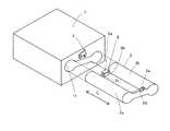
図1は、本発明の一実施形態による熱転写プリンタの全体構成を示した斜視図である。図2は、本発明の一実施形態による印字ヘッド部のクリーニング用部材の全体構成を説明するための斜視図である。図3〜図6は、図2に示した本発明の一実施形態による印字ヘッド部のクリーニング用部材の詳細構造を説明するための図である。図7は、本発明の一実施形態による印画時の状態を説明するための断面図である。図1〜図7を参照して、本発明の一実施形態による印字ヘッド部のクリーニング用部材の構造について説明する。 FIG. 1 is a perspective view showing the overall configuration of a thermal transfer printer according to an embodiment of the present invention. FIG. 2 is a perspective view for explaining the overall configuration of the print head cleaning member according to the embodiment of the present invention. 3 to 6 are views for explaining the detailed structure of the cleaning member for the print head unit according to the embodiment of the present invention shown in FIG. FIG. 7 is a cross-sectional view for explaining a state during printing according to an embodiment of the present invention. With reference to FIGS. 1-7, the structure of the cleaning member of the print head part by one Embodiment of this invention is demonstrated.
本発明の一実施形態による熱転写プリンタでは、図1に示すように、装置本体1の側部に設けられたインクカートリッジ挿入孔1aに、インクカートリッジ2が挿入される。また、装置本体1の側部には、インクカートリッジ2を挿入した状態で固定するための係合部材3が設けられている。また、図2に示すように、インクカートリッジ2は、インクリボン(インクシート)9(図7参照)が収納される一対のインクリボン収納部2aおよび2bと、一対のインクリボン収納部2aおよび2bを連結するための一対の連結部2cおよび2dと、連結部2dに設けられた係合部材3に係合する凹状の係合部2eとを含んでいる。 In the thermal transfer printer according to the embodiment of the present invention, as shown in FIG. 1, the
ここで、本実施形態では、インクカートリッジ2の挿入方向先端部側の連結部2cには、図2および図3に示すように、クリーニング用部品8を取り付けるための凹部2fが設けられている。この凹部2fは、その凹部2fに取り付けられたクリーニング用部品8がB方向にずれることがないようにB方向の長さを有する。つまり、凹部2fは、クリーニング用部品8の取付位置の位置決め部としても機能する。また、本実施形態では、使用済のインクカートリッジ2をクリーニング用部品8のガイド部として利用する。 Here, in the present embodiment, as shown in FIGS. 2 and 3, a
また、装置本体1の内部には、図7に示すように、印字を行うためのサーマルヘッド(印字ヘッド)4と、サーマルヘッド4に対向するように配置されたプラテンローラ5と、用紙10を搬送するための送りローラ6と、送りローラ6に対して所定の押圧力で押圧される押さえローラ7とが設けられている。また、サーマルヘッド4は、支持軸4aと、アーム部4bと、印字ヘッド部4cとを有している。また、サーマルヘッド4は、装置本体1に支持軸4aを中心として回動可能に取り付けられている。 In addition, as shown in FIG. 7, a thermal head (printing head) 4 for performing printing, a
また、本実施形態では、クリーニング部材は、使用済のインクカートリッジ2と、クリーニング用部品8とによって構成される。クリーニング用部品8は、フェルトなどからなるクリーニング部8aと、樹脂製の取付部8bとを有している。クリーニング部8aには、図3および図4に示すように、印字ヘッド部4cとの当接面8cのインクカートリッジ2の挿入方向の端部および挿入方向と直交する方向の端部に、面取り部8dおよび8eが設けられている。クリーニング部8aの当接面8cとは反対側の面は、両面テープなどに
より、樹脂製の取付部8bに取り付けられている。また、取付部8bは、図4に示すように、コの字形状を有するとともに、コの字形状の先端部に、インクカートリッジ2の凹部2fに係合可能で、かつ、弾性変形可能な一対のフック形状部8fが設けられている。この弾性変形可能な一対のフック形状部8fにより、クリーニング用部品8をインクカートリッジ2に対して脱着可能に取り付けることが可能になる。In this embodiment, the cleaning member includes the used
図8および図9は、本発明の一実施形態によるクリーニング部材を用いた印字ヘッド部のクリーニング動作を説明するための図である。次に、図2、図3、図5、図6、図8および図9を参照して、本発明の一実施形態による印字ヘッド部のクリーニング動作について説明する。本実施形態による印字ヘッド部4cのクリーニングを行う際には、まず、図2に示すように、使用済のインクカートリッジ2を装置本体1から矢印A方向に抜き取る。その後、図2および図3に示すように、クリーニング用部品8をインクカートリッジ2の凹部2fに取り付ける。これにより、図5、図6および図8に示した状態になる。そして、クリーニング用部品8を取り付けたインクカートリッジ2を装置本体1の側部1aから挿入することにより、図9に示すように、インクカートリッジ2をガイドとしてクリーニング部8aを印字ヘッド部4cに当接させる。そして、図9に示した状態で、図8のC方向へ往復移動させることによって、印字ヘッド部4cに付着した異物をクリーニング部8aにより拭き取る。このようにして、本実施形態によるクリーニング動作が行われる。 8 and 9 are diagrams for explaining the cleaning operation of the print head unit using the cleaning member according to the embodiment of the present invention. Next, with reference to FIG. 2, FIG. 3, FIG. 5, FIG. 6, FIG. 8, and FIG. When cleaning the
次に、図7を参照して、本発明の一実施形態による熱転写プリンタの印画動作を説明する。送りローラ6が図7の矢印F1方向に回転することによって、用紙10を用紙搬送方向(図7の矢印E1方向)に搬送する。このとき、インクカートリッジ2のインクリボン収納部2bから、インクリボン9が供給される。この用紙10およびインクリボン9を搬送しながら、印字ヘッド部4cが用紙10およびインクリボン9を介してプラテンローラ5に押圧されることによって、印画が行われる。 Next, the printing operation of the thermal transfer printer according to the embodiment of the present invention will be described with reference to FIG. As the
本実施形態では、上記のように、使用済インクカートリッジ2を、印字ヘッド部4cにクリーニング用部品8を当接させるためのガイド部として利用することによって、クリーニング用部品8にガイド部を設ける必要がないので、クリーニング用部品8の構造を簡素化することができるとともに、小型化を図ることができる。また、使用済のインクカートリッジ2をガイド部として利用することによって、使用済のインクカートリッジ2の再利用を図ることもできるとともに、ガイド部を別途設ける必要がない分、部品点数を削減することができる。 In the present embodiment, as described above, the used
また、本実施形態では、クリーニング用部品8を、使用済のインクカートリッジ2に取り付けるための樹脂製の取付部8bと、印字ヘッド部4cをクリーニングするためのクリーニング部8aとを含むように構成することによって、フェルトなどからなるクリーニング部8aとは別に樹脂製の取付部8bが設けられるので、その樹脂製の取付部8bにより、容易に、クリーニング部8aをインクカートリッジ2に取り付けることができる。 Further, in the present embodiment, the
また、本実施形態では、クリーニング部8aの当接面8cの少なくともインクカートリッジ2の挿入方向の端部に、面取り部8dを設けることによって、クリーニングを行う際にクリーニング用部品8を印字ヘッド部4cに円滑に当接させることができる。 In the present embodiment, the
また、本実施形態では、インクカートリッジ2に、クリーニング用部品8が取り付けられるとともに取付位置の位置決めとなる凹部2fを設けることによって、その凹部2fにより、クリーニング用部品8の取付位置がずれるのを抑制することができる。また、クリーニング用部品8を、インクカートリッジ2の凹部2fに脱着可能に構成することによって、消耗品であるクリーニング用部品8を交換することができる。 In the present embodiment, the
なお、今回開示された実施形態は、すべての点で例示であって制限的なものではないと考えられるべきである。本発明の範囲は、上記した実施形態の説明ではなく特許請求の範囲によって示され、さらに特許請求の範囲と均等の意味および範囲内でのすべての変更が含まれる。 The embodiment disclosed this time should be considered as illustrative in all points and not restrictive. The scope of the present invention is shown not by the above description of the embodiments but by the scope of claims for patent, and further includes all modifications within the meaning and scope equivalent to the scope of claims for patent.
たとえば、上記実施形態では、画像形成装置の一例としての熱転写プリンタの印字ヘッド部のクリーニング部材に適用した例を示したが、本発明はこれに限らず、印字を行うための印字ヘッド部を有する画像形成装置であれば、熱転写プリンタ以外の他の画像形成装置の印字ヘッド部のクリーニング部材にも適用可能である。 For example, in the above-described embodiment, an example in which the present invention is applied to a cleaning member of a print head portion of a thermal transfer printer as an example of an image forming apparatus has been described. However, the present invention is not limited thereto, and a print head portion for performing printing is provided. Any image forming apparatus can be applied to a cleaning member for a print head portion of an image forming apparatus other than the thermal transfer printer.
また、上記実施形態では、クリーニング用部品をインクカートリッジに脱着可能に取り付ける例を示したが、本発明はこれに限らず、両面テープ(粘着テープ)などにより、クリーニング用部品を脱着不可能にインクカートリッジに固着するようにしてもよい。 In the above embodiment, the cleaning part is detachably attached to the ink cartridge. However, the present invention is not limited to this, and the cleaning part is not removable with a double-sided tape (adhesive tape) or the like. You may make it adhere to a cartridge.
2 インクカートリッジ
2a、2b インクリボン収納部(インクシート収納部)
2c、2d 連結部
2f 凹部
4c 印字ヘッド部
8 クリーニング用部品
8a クリーニング部
8b 取付部2
2c,
Claims (5)
Translated fromJapanese前記クリーニング用部品は、
使用済のインクカートリッジに取り付けるための樹脂製の取付部と、
前記取付部に取り付けられ、前記印字ヘッド部に当接することにより前記印字ヘッド部をクリーニングするためのクリーニング部とを含み、
前記インクカートリッジを、前記印字ヘッド部に前記クリーニング用部品を当接させるためのガイド部として利用し、
前記クリーニング部の当接面の、少なくともインクカートリッジの挿入方向の端部には、面取り部が設けられ、
前記インクカートリッジは、一対のインクシート収納部と、前記一対のインクシート収納部を連結する一対の連結部と、前記一対の連結部のうち前記インクカートリッジの挿入方向先端部側の連結部に設けられ、前記クリーニング用部品が取り付けられるとともに取付位置の位置決めとなる凹部とを含み、
前記クリーニング用部品は、前記凹部に脱着可能に取り付けられる、印字ヘッドのクリーニング用部材。In the print head cleaning member provided with cleaning parts for cleaning the print head,
The cleaning parts are:
A resin mounting part for mounting on a used ink cartridge;
A cleaning part attached to the attachment part, for cleaning the print head part by contacting the print head part,
The ink cartridge is used as a guide part for bringing the cleaning component into contact with the print head part,
A chamfered portion is provided at least at the end of the contact surface of the cleaning portion in the insertion direction of the ink cartridge,
The ink cartridge is provided in a pair of ink sheet storage portions, a pair of connection portions that connect the pair of ink sheet storage portions, and a connection portion on the tip side in the insertion direction of the ink cartridge among the pair of connection portions. And includes a recess to which the cleaning component is attached and the attachment position is positioned,
The cleaning component is a print head cleaning member that is detachably attached to the recess.
前記インクカートリッジに取り付けられ、印字ヘッド部のクリーニングを行うためのクリーニング用部品とを備え、
前記インクカートリッジを、前記印字ヘッド部に前記クリーニング用部品を当接させるためのガイド部として利用する、印字ヘッド部のクリーニング部材。Used ink cartridges,
A cleaning component attached to the ink cartridge for cleaning the print head portion;
A cleaning member for a print head portion, wherein the ink cartridge is used as a guide portion for bringing the cleaning component into contact with the print head portion.
前記クリーニング用部品を前記インクカートリッジに取り付けるための樹脂製の取付部と、
前記取付部に取り付けられ、前記印字ヘッド部に当接することにより前記印字ヘッド部をクリーニングするためのクリーニング部とを含む、請求項2に記載の印字ヘッド部のクリーニング部材。The cleaning parts are:
A resin mounting portion for mounting the cleaning component to the ink cartridge;
The print head portion cleaning member according to claim 2, further comprising: a cleaning portion attached to the attachment portion and cleaning the print head portion by contacting the print head portion.
前記クリーニング用部品は、前記凹部に脱着可能に取り付けられる、請求項2〜4のいずれか1項に記載の印字ヘッド部のクリーニング部材。The ink cartridge is provided in a pair of ink sheet storage portions, a pair of connection portions that connect the pair of ink sheet storage portions, and a connection portion on the tip side in the insertion direction of the ink cartridge among the pair of connection portions. And includes a recess to which the cleaning component is attached and the attachment position is positioned,
The print head cleaning member according to claim 2, wherein the cleaning component is detachably attached to the recess.
Priority Applications (3)
| Application Number | Priority Date | Filing Date | Title |
|---|---|---|---|
| JP2005126122AJP2006297852A (en) | 2005-04-25 | 2005-04-25 | Cleaning member for printing head section |
| EP06252079.6AEP1719623B1 (en) | 2005-04-25 | 2006-04-13 | Print head cleaning member |
| US11/407,065US7703881B2 (en) | 2005-04-25 | 2006-04-20 | Print head cleaning member |
Applications Claiming Priority (1)
| Application Number | Priority Date | Filing Date | Title |
|---|---|---|---|
| JP2005126122AJP2006297852A (en) | 2005-04-25 | 2005-04-25 | Cleaning member for printing head section |
Publications (1)
| Publication Number | Publication Date |
|---|---|
| JP2006297852Atrue JP2006297852A (en) | 2006-11-02 |
Family
ID=36659907
Family Applications (1)
| Application Number | Title | Priority Date | Filing Date |
|---|---|---|---|
| JP2005126122APendingJP2006297852A (en) | 2005-04-25 | 2005-04-25 | Cleaning member for printing head section |
Country Status (3)
| Country | Link |
|---|---|
| US (1) | US7703881B2 (en) |
| EP (1) | EP1719623B1 (en) |
| JP (1) | JP2006297852A (en) |
Families Citing this family (2)
| Publication number | Priority date | Publication date | Assignee | Title |
|---|---|---|---|---|
| JP2007069363A (en) | 2005-09-05 | 2007-03-22 | Funai Electric Co Ltd | Image forming apparatus |
| MX355341B (en)* | 2010-11-15 | 2018-04-16 | Zih Corp | Media processing device and associated system. |
Family Cites Families (9)
| Publication number | Priority date | Publication date | Assignee | Title |
|---|---|---|---|---|
| JPS60155487A (en)* | 1984-01-25 | 1985-08-15 | Toshiba Corp | Image-forming device |
| JPS6131279A (en)* | 1984-07-24 | 1986-02-13 | Ricoh Co Ltd | Tape cassette |
| JPS61164878A (en)* | 1985-01-18 | 1986-07-25 | Nec Corp | Thermal transfer recorder |
| JPS63222878A (en)* | 1987-03-12 | 1988-09-16 | Matsushita Electric Ind Co Ltd | Ink sheet cassette for thermal transfer |
| US6000780A (en)* | 1994-04-08 | 1999-12-14 | Hewlett-Packard Company | Wiping system for inkjet printer |
| JPH106491A (en) | 1996-06-26 | 1998-01-13 | Seiko Instr Inc | Ink jet recorder and head gap holding mechanism used therefor |
| JP2000141672A (en) | 1998-11-06 | 2000-05-23 | Fine Technol Kk | Method for cleaning head wiper of ink-jet printer |
| US7344325B2 (en)* | 1999-01-25 | 2008-03-18 | Fargo Electronics, Inc. | Identification card printer having ribbon cartridge with cleaner roller |
| JP3970097B2 (en)* | 2002-06-07 | 2007-09-05 | キヤノン株式会社 | Recording device |
- 2005
- 2005-04-25JPJP2005126122Apatent/JP2006297852A/enactivePending
- 2006
- 2006-04-13EPEP06252079.6Apatent/EP1719623B1/ennot_activeCeased
- 2006-04-20USUS11/407,065patent/US7703881B2/ennot_activeExpired - Fee Related
Also Published As
| Publication number | Publication date |
|---|---|
| EP1719623A3 (en) | 2009-04-08 |
| US7703881B2 (en) | 2010-04-27 |
| US20060238562A1 (en) | 2006-10-26 |
| EP1719623B1 (en) | 2014-03-19 |
| EP1719623A2 (en) | 2006-11-08 |
Similar Documents
| Publication | Publication Date | Title |
|---|---|---|
| US7736076B2 (en) | Ribbon cassette and printer | |
| US7988268B2 (en) | Ink tube non-contact image forming apparatus | |
| JPH07117308A (en) | Inkjet recording device and information processing system | |
| JP4196176B2 (en) | Optical disc ejection device and ink jet recording apparatus equipped with the ejection device | |
| JP5538859B2 (en) | Recording device | |
| EP1231063A2 (en) | Cartridge, carriage, ink jet recording apparatus, and recording head | |
| US7808518B2 (en) | Ink sheet cartridge | |
| JP2011230416A (en) | Inkjet recorder | |
| JP2006159715A (en) | Cartridge fixing device | |
| JP2006297852A (en) | Cleaning member for printing head section | |
| JP2013233709A (en) | Inkjet recording apparatus | |
| JP3224133B2 (en) | Scanning image forming apparatus | |
| JP3632603B2 (en) | Inkjet printer | |
| JP2006315362A (en) | Ink sheet cartridge | |
| JPH11132788A (en) | Linear encoder support device and image recording device | |
| JP4018704B2 (en) | Ribbon cassette | |
| JP2010064826A (en) | Winding tube fixing apparatus and printer using the same | |
| JP2004264688A (en) | Image carrier drive mechanism | |
| JPH08300750A (en) | Printing device and printing cassette used therefor | |
| JP3331741B2 (en) | Ink jet recording device | |
| JP2007118436A (en) | Recording device | |
| JP4710641B2 (en) | Liquid ejecting apparatus and control method thereof | |
| JP2005314080A (en) | Disk, encoder and image forming apparatus | |
| JP2000015911A (en) | Ink ribbon cassette provided with a thin plate-like elastic member covering the exposed portion of the ink ribbon | |
| JPH04201567A (en) | Ink jet recording device |