JP2006290462A - Equipment for instant contact of at least two types of products - Google Patents
Equipment for instant contact of at least two types of productsDownload PDFInfo
- Publication number
- JP2006290462A JP2006290462AJP2006088814AJP2006088814AJP2006290462AJP 2006290462 AJP2006290462 AJP 2006290462AJP 2006088814 AJP2006088814 AJP 2006088814AJP 2006088814 AJP2006088814 AJP 2006088814AJP 2006290462 AJP2006290462 AJP 2006290462A
- Authority
- JP
- Japan
- Prior art keywords
- container
- intermediate member
- skirt
- sealing
- compartment
- Prior art date
- Legal status (The legal status is an assumption and is not a legal conclusion. Google has not performed a legal analysis and makes no representation as to the accuracy of the status listed.)
- Pending
Links
Images


Classifications
- B—PERFORMING OPERATIONS; TRANSPORTING
- B05—SPRAYING OR ATOMISING IN GENERAL; APPLYING FLUENT MATERIALS TO SURFACES, IN GENERAL
- B05B—SPRAYING APPARATUS; ATOMISING APPARATUS; NOZZLES
- B05B11/00—Single-unit hand-held apparatus in which flow of contents is produced by the muscular force of the operator at the moment of use
- B05B11/0005—Components or details
- B05B11/0078—Arrangements for separately storing several components
- B05B11/0081—Arrangements for separately storing several components and for mixing the components in a common container as a mixture ready for use before discharging the latter
- B—PERFORMING OPERATIONS; TRANSPORTING
- B05—SPRAYING OR ATOMISING IN GENERAL; APPLYING FLUENT MATERIALS TO SURFACES, IN GENERAL
- B05B—SPRAYING APPARATUS; ATOMISING APPARATUS; NOZZLES
- B05B11/00—Single-unit hand-held apparatus in which flow of contents is produced by the muscular force of the operator at the moment of use
- B05B11/01—Single-unit hand-held apparatus in which flow of contents is produced by the muscular force of the operator at the moment of use characterised by the means producing the flow
- B05B11/10—Pump arrangements for transferring the contents from the container to a pump chamber by a sucking effect and forcing the contents out through the dispensing nozzle
- B05B11/1042—Components or details
- B05B11/1043—Sealing or attachment arrangements between pump and container
- B05B11/1046—Sealing or attachment arrangements between pump and container the pump chamber being arranged substantially coaxially to the neck of the container
- B05B11/1047—Sealing or attachment arrangements between pump and container the pump chamber being arranged substantially coaxially to the neck of the container the pump being preassembled as an independent unit before being mounted on the container
- B—PERFORMING OPERATIONS; TRANSPORTING
- B65—CONVEYING; PACKING; STORING; HANDLING THIN OR FILAMENTARY MATERIAL
- B65D—CONTAINERS FOR STORAGE OR TRANSPORT OF ARTICLES OR MATERIALS, e.g. BAGS, BARRELS, BOTTLES, BOXES, CANS, CARTONS, CRATES, DRUMS, JARS, TANKS, HOPPERS, FORWARDING CONTAINERS; ACCESSORIES, CLOSURES, OR FITTINGS THEREFOR; PACKAGING ELEMENTS; PACKAGES
- B65D51/00—Closures not otherwise provided for
- B65D51/24—Closures not otherwise provided for combined or co-operating with auxiliary devices for non-closing purposes
- B65D51/28—Closures not otherwise provided for combined or co-operating with auxiliary devices for non-closing purposes with auxiliary containers for additional articles or materials
- B65D51/2807—Closures not otherwise provided for combined or co-operating with auxiliary devices for non-closing purposes with auxiliary containers for additional articles or materials the closure presenting means for placing the additional articles or materials in contact with the main contents by acting on a part of the closure without removing the closure, e.g. by pushing down, pulling up, rotating or turning a part of the closure, or upon initial opening of the container
- B65D51/2857—Closures not otherwise provided for combined or co-operating with auxiliary devices for non-closing purposes with auxiliary containers for additional articles or materials the closure presenting means for placing the additional articles or materials in contact with the main contents by acting on a part of the closure without removing the closure, e.g. by pushing down, pulling up, rotating or turning a part of the closure, or upon initial opening of the container the additional article or materials being released by displacing or removing an element enclosing it
- B65D51/2864—Closures not otherwise provided for combined or co-operating with auxiliary devices for non-closing purposes with auxiliary containers for additional articles or materials the closure presenting means for placing the additional articles or materials in contact with the main contents by acting on a part of the closure without removing the closure, e.g. by pushing down, pulling up, rotating or turning a part of the closure, or upon initial opening of the container the additional article or materials being released by displacing or removing an element enclosing it the element being a plug or like element closing a passage between the auxiliary container and the main container
Landscapes
- Engineering & Computer Science (AREA)
- Mechanical Engineering (AREA)
- Closures For Containers (AREA)
- Package Specialized In Special Use (AREA)
- Containers And Packaging Bodies Having A Special Means To Remove Contents (AREA)
Abstract
Translated fromJapaneseDescription
Translated fromJapanese本発明は、別個に収蔵された少なくとも2種類の製品、特に2種類の化粧品を即席接触させるための器具に関する。また本発明は、こうした2種類の製品を混ぜ合わせることによって得られる混合物を供出するためのシステムに関する。本発明は特に、ヘアトリートメント用化粧剤の即席調製および供出に役立つものである。 The present invention relates to a device for instant contact of at least two types of separately stored products, in particular two types of cosmetics. The invention also relates to a system for delivering a mixture obtained by mixing these two types of products. The present invention is particularly useful for the instant preparation and delivery of hair treatment cosmetics.
「化粧品(cosmetic product)」との用語は、1993年6月14日付けEC Council Directive 93/35/CEEにおいて規定されるような製品を意味するものである。 The term “cosmetic product” means a product as defined in the EC Council Directive 93/35 / CEE dated 14 June 1993.
ヘアカラーリングの分野では、多くの染色組成物が、2種類の製品(一般には着色剤および酸化剤)の即席混合によって調製されている。この製品は、安定性に関する理由から、染色組成物を使用するときまで互いに接触しないようにする必要がある。 In the field of hair coloring, many dyeing compositions are prepared by instant mixing of two products (generally colorants and oxidants). This product needs to be kept out of contact with each other until the dyeing composition is used for stability reasons.
ヘアカラーリングの分野では、近年になって、混合器具が提供されるようになった。これは、いくらか自動的な様式で、2種類の製品の個別パッケージングを、そして染色組成物を使用する際には、その即席混合を実現するものである。こうしたシステムは高価であり、しかも製造が面倒である。上記製品のそれぞれを収容する二つの分室間の防漏出性を実現するのは、特に、これら分室間に設けられる仕切りが、分室が連通状態とされるときに破られるよう構成されたフィルムの形態をとるものである場合には困難である。その上、充填されることになる製品と適合性のある素材を見つけるのは、こうした素材の少なくともいくつかのものが有する攻撃特性のために、しばしば困難になることがある。 In the field of hair coloring, mixing devices have recently been provided. This achieves the individual packaging of the two products in a somewhat automatic fashion, and the instant mixing when using the dye composition. Such systems are expensive and cumbersome to manufacture. The realization of leakage prevention between the two compartments containing each of the products mentioned above is particularly in the form of a film configured such that the partition provided between these compartments is broken when the compartments are brought into communication. It is difficult to take Moreover, finding materials that are compatible with the product to be filled can often be difficult due to the aggressive nature of at least some of these materials.
得られた製品混合物の供出に関して、さまざまな問題が生じる別の分野においては、特許文献1が、二つの隔離された分室を具備してなる、公知の、すぐに使用できる供給ボトルを開示している。こうした供給ボトルの本体部は標準的なものではなく、しかもネック(この上に乳頭を取り付けることができる)から、ある距離を置いて環状のくびれを有する。閉塞要素が、この環状くびれと係合するよう、そして第1の分室を閉塞するよう、上記本体部に取り付けられる。この閉塞要素は、第2の分室の底部を形成する。このタイプの供給ボトルが提起する問題は、二つの分室への充填が困難であるという事実に起因する。特許文献2は、先に説明したタイプの公知の器具を開示しているが、やはりこのものも、第2の分室の充填ならびに閉塞に関する問題をはらんでいる。 In another area where various problems arise with respect to the delivery of the resulting product mixture, U.S. Pat. No. 6,099,077 discloses a known ready-to-use supply bottle comprising two isolated compartments. Yes. The body of such a supply bottle is not standard and has an annular constriction at a distance from the neck (on which the teat can be mounted). A closure element is attached to the body portion to engage the annular constriction and to close the first compartment. This closure element forms the bottom of the second compartment. The problem raised by this type of supply bottle is due to the fact that it is difficult to fill the two compartments.
特許文献3もまた、2種類の製品を即席混合するための公知の器具を開示している。このものでは、第1の製品は容器内に収容され、かつ第2の製品は、この容器の閉塞要素のチャンバー内に分離状態で収容される。この2種類の製品の混合は、閉塞要素を容器に対してスライドさせるだけで行える。実際には、閉塞要素のチャンバーは、初めは、容器に取り付けられた閉塞部材の中間取り付け部材によって密閉されており、上記スライド動作がなされたとき、チャンバーが開放され、そして中間部材に形成された流路によってチャンバーと容器とが連通状態となり得る。製品は、この流路を経て、チャンバーから容器内へと、場合によっては重力作用で流れ込む。
こうしたタイプの器具は次のような問題を提起する。すなわち、製品の流動を可能にするよう形成された上記流路は、チャンバー内に貯蔵された製品が、速やかにそして完全に流れ出るのを妨げる。実際には、こうした流路は、チャンバーを密閉するよう構成された中間部材の閉塞要素を、容器のネックにおけるこの中間部材の取り付け手段に対して接続する素材のブリッジ同士の間に形成される。流路の数は素材ブリッジの数と等しく、チャンバーを出る製品の流れは、存在する流路の数と同数の細流へと分岐する。実際には、この流路が詰まってしまい、得られた混合物が使用者の意図したものと一致しなくなる恐れがある。こうした器具によって得られる混合物の信頼性ならびに再現性は保証されない。
したがって、本発明の目的の一つは、2種類の製品を別個に収蔵しかつそれを混合状態で供出するための器具であって、上記問題の全てをあるいはそのいくつかを解決する器具を提供することである。 Accordingly, one of the objects of the present invention is to provide an apparatus for separately storing two types of products and delivering them in a mixed state, and solving all or some of the above problems. It is to be.
この目的のために、本発明は、第1の分室および第2の分室それぞれに分離状態で収蔵された、少なくとも2種類の製品を即席接触させるための器具を提供し、
上記第1の分室は容器によって少なくとも部分的に形成され、
上記第2の分室は、上記容器に対して中間部材を介して接続された構造体によって少なくとも部分的に形成され、この構造体は上記容器から取り外し可能な閉塞要素を形成しており、
上記構造体は、操作行為がなされると、上記二つの分室が互いに隔離された第1の様態から、上記分室同士が互いに連通可能となる第2の様態へと、上記中間部材に対して動くよう構成されており、
上記中間部材は、上記容器に対して着脱可能であると共に、上記容器と連通状態となるよう構成された管路を具備してなり、
上記構造体は、その周囲に上記第2の分室が形成されるシーリング要素を具備してなり、
このシーリング要素は、上記操作行為がなされるまで、上記二つの分室を漏れが生じないよう互いに隔離する部分を具備してなる。For this purpose, the present invention provides an instrument for instant contact of at least two types of products stored separately in a first compartment and a second compartment,
The first compartment is at least partially formed by a container;
The second compartment is formed at least in part by a structure connected to the container via an intermediate member, the structure forming a closure element removable from the container;
When an operation is performed, the structure moves relative to the intermediate member from a first mode in which the two compartments are isolated from each other to a second mode in which the compartments can communicate with each other. It is configured as
The intermediate member is detachable with respect to the container, and includes a conduit configured to be in communication with the container.
The structure comprises a sealing element around which the second compartment is formed,
The sealing element comprises a portion that isolates the two compartments from each other so that no leakage occurs until the manipulation action is performed.
好ましくは、シーリング要素の上記部分は、漏れが生じないよう管路内に差し込まれる。 Preferably, said part of the sealing element is inserted into the conduit so that no leakage occurs.
有利なことを言えば、上記中間部材は、容器と係合するよう構成された第1の固定手段と、閉塞要素と係合するよう構成された第2の固定手段とを具備してなることができる。この場合、第1の固定手段は、容器外周部と協働して、中間部材を容器に対して軸方向に保持するよう構成されたスナップ式結合手段をなしていてもよい。任意選択で、この第1の固定手段はまた、容器外周部と係合した状態では、中間部材が容器に対して回転できないようにする手段を備えていてもよい。たとえば第2の固定手段は、閉塞要素の外側スカートに設けた相手方ネジ山と係合するよう構成されたネジ山を具備してなる。 Advantageously, the intermediate member comprises first fixing means configured to engage the container and second fixing means configured to engage the closure element. Can do. In this case, the first fixing means may be a snap-type coupling means configured to hold the intermediate member in the axial direction with respect to the container in cooperation with the container outer peripheral portion. Optionally, the first securing means may also comprise means for preventing the intermediate member from rotating relative to the container when engaged with the container periphery. For example, the second securing means comprises a thread configured to engage a counter thread provided on the outer skirt of the closure element.
特に、中間部材は、管路の周りに形成された鍔部に関して反対方向にそれぞれ延在する第1のスカートおよび第2のスカートを具備することができる。 In particular, the intermediate member may comprise a first skirt and a second skirt, each extending in opposite directions with respect to a buttock formed around the conduit.
この場合、第1のスカートは第1の固定手段を支持でき、そして第2のスカートが第2の固定手段を支持できる。 In this case, the first skirt can support the first fixing means and the second skirt can support the second fixing means.
有利なことを言えば、中間部材は、容器内に配されると共に、この容器に対して中間部材を、漏れが生じないように確実に取り付けることができるよう構成された第1のシーリングスカートを具備してなる。たとえば、この第1のシーリングスカートは、第1の様態においては、部分的に上記管路を形成することができ、しかもシーリング要素の上記部分と係合できる。 Advantageously, the intermediate member is arranged in a container and has a first sealing skirt configured to ensure that the intermediate member can be securely attached to the container without leaks. It has. For example, the first sealing skirt can partially form the conduit in the first embodiment and can engage the portion of the sealing element.
好ましくは、中間部材は、第2の分室を形成する筒状壁の内面と協働する第2のシーリングスカートを具備してなり、この第2のシーリングスカートは、シーリング要素よりも大きな内部断面積を具備しており、これによって第1の様態では、第2の分室が、この第2のシーリングスカートと、鍔部と、シーリング要素とから部分的に形成される。 Preferably, the intermediate member comprises a second sealing skirt cooperating with the inner surface of the cylindrical wall forming the second compartment, the second sealing skirt having a larger internal cross-sectional area than the sealing element. Thereby, in the first aspect, the second compartment is partly formed from this second sealing skirt, the collar and the sealing element.
第2のシーリングスカートは、第2の様態に対応する、中間部材に対する閉塞要素のポジションを識別するために上記筒状壁と係合するよう構成できる。特に、筒状壁は、第2の様態において、第2のシーリングスカートが具備する環状凸条に対して当接するよう構成された突出部を備えていてもよい。 The second sealing skirt can be configured to engage the cylindrical wall to identify the position of the closure element relative to the intermediate member, corresponding to the second aspect. In particular, in the second aspect, the cylindrical wall may include a protrusion configured to abut against an annular ridge provided in the second sealing skirt.
第1の実施形態では、容器はガラスから、中間部材は熱可塑性素材、好ましくはポリエチレン、特に高密度ポリエチレンから、閉塞要素は熱可塑性素材、好ましくはポリプロピレンから形成される。 In a first embodiment, the container is made of glass, the intermediate member is made of a thermoplastic material, preferably polyethylene, in particular high density polyethylene, and the closure element is made of a thermoplastic material, preferably polypropylene.
本発明はまた、本発明による器具をパッケージングするための方法を提供し、この方法は、
上記容器に第1の製品を充填し、
上記構造体におけるシーリング要素の周囲に、これとは別個に第2の製品を充填し、
密閉されたユニットを形成するよう上記構造体に上記中間部材を取り付け、
密閉されたユニットを容器に組み付けるものである。The present invention also provides a method for packaging a device according to the present invention, the method comprising:
Filling the container with the first product,
A second product is filled separately around the sealing element in the structure,
Attach the intermediate member to the structure to form a sealed unit,
A sealed unit is assembled to a container.
本発明による器具は有利なパッケージング方法を実現し、この方法では、第1の製品および第2の製品のパッケージングは、互いに独立した別個のパッケージングラインにおいて実施できる。 The device according to the invention provides an advantageous packaging method, in which the packaging of the first product and the second product can be carried out in separate packaging lines which are independent of each other.
有利なことを言えば、本発明の対象は収蔵供出器具であり、このものは、一方では、本発明による器具を、そして他方では、容器内で生成された製品混合物を供出するために、閉塞要素が中間部材から取り外された際に中間部材に取り付けられるよう構成された供出要素を具備してなる。 Advantageously, the subject of the invention is a storage and delivery device, which is occluded on the one hand for delivering the device according to the invention and on the other hand the product mixture produced in the container. A dispensing element configured to be attached to the intermediate member when the element is removed from the intermediate member.
特に、供出要素は外側囲壁を具備してなるものであってもよく、この外側囲壁に対してポンプが取り付けられ、このポンプの上には操作供出手段が配設される。とりわけ、この外側囲壁は、中間部材に対して供給要素を固定する、元に戻すことが可能な手段を備えることができる。 In particular, the delivery element may comprise an outer enclosure, to which a pump is attached, on which an operating delivery means is arranged. In particular, the outer enclosure can be provided with a reversible means for securing the supply element with respect to the intermediate member.
たとえば、供出要素は、管路内に差し込まれた浸液チューブを具備してなるものであってもよい。 For example, the delivery element may comprise an immersion tube inserted into the conduit.
概して、本発明の対象は、上記器具内に別個に貯蔵された2種類の製品を即席混合することによって得られる化粧剤を供出するためのユニットの用法である。 In general, the subject of the present invention is the use of a unit for delivering a cosmetic obtained by instant mixing of two different products stored separately in the appliance.
本発明は以下の説明および添付図面からより良く理解できるであろう。これらは参考のために提示したに過ぎず、決して本発明を限定するものではない。 The invention will be better understood from the following description and the accompanying drawings. These are provided for reference only and do not limit the invention in any way.
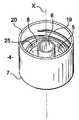
図1は本発明による器具1を示しており、この器具1は容器2を具備し、この容器2は、それ自体の閉塞要素4が上方に配設された中間部材3を備える。 FIG. 1 shows a
特に、容器2は透明なガラス製のものであり、10ないし100mLの間の、好ましくは約25mLの容積を有する。容器2には、好ましくは液体である第1の製品P1が入っている。容器2は、その底部から肩部にかけて僅かにテーパー形状をなしており、この肩部に中間部材3および閉塞要素4が設けられる。変形例においては、容器2には、底部ならびに肩部から離れた位置に、くびれを設けることができる。この場合、くびれは、肩部における容器の横断面が底部のレベルにおける横断面と一致するように、つまり前者が後者と重なり合うよう配置されることが好ましい。そうした容器には、パッケージングラインへの輸送が容易に行えるという利点がある。 In particular, the
閉塞要素4は、その底部7から突出するシーリング要素6の周囲にチャンバー5(図2参照)を形成する。シーリング要素6は、軸線Xに沿って、底部7に対して垂直に立設されている。 The
シーリング要素6は、中空あるいは中実スタッドの形態とすることができる。それは、チャンバー5を部分的に画定する壁を形成し、チャンバー5はシーリング要素6の周囲に形成される。 The sealing
チャンバー5は底部7によって部分的に形成される。チャンバー5は、内面についてはシーリング要素6によって、また外面については、やはり底部7から直立する筒状壁8によって形成される。この筒状壁8はシーリング要素6を取り囲んでいる。筒状壁8はまた、軸線Xに沿って、底部7に対して垂直に立設されている。チャンバー5は、シーリング要素6と筒状壁8との間に形成されるが、これらはそれぞれ、いかなる横断面を有していてもよい。 The
シーリング要素6は好ましくは中空チューブであり、しかもそれはたとえば円形外部横断面を有する。筒状壁8はたとえば、シーリング要素6のそれよりも大きな直径の、円形内部横断面を有し、この結果、筒状壁8とシーリング要素6とは、軸線Xを中心として、同心状に形成されている。チャンバー5はそれゆえ環状断面となっている。 The sealing
チャンバー5は1ないし20mLの、好ましくは約5mLの容積を有する。このチャンバー5は、第1の製品P1とは異なる第2の製品P2を収容するものとなる。好ましくは、第2の製品P2もまた液体である。とりわけ、製品P1およびP2の混合物は、安定したものではない。製品P1およびP2は、互いに分離された状態で貯蔵され、それゆえ混合物を使用するときまで混合されない。
軸線Xは縦方向軸線に対応し、図3、図4および図6の断面図は、それを通るよう描かれている。実際には、閉塞要素4が容器2を密閉するよう設けられるので、この閉塞要素4は、軸線Xが、容器2の対称縦方向軸線および/または回転軸線と重なり合うよう、この容器2に取り付けられる。 Axis X corresponds to the longitudinal axis, and the cross-sectional views of FIGS. 3, 4 and 6 are drawn through it. In practice, since the
チャンバー5は、器具1が密閉された状態にある第1の貯蔵様態では、容器2の内容物から隔離されるようになっている。このために、中間部材3は、第1の様態において、チャンバー5が閉塞されることを可能としている。閉塞要素4の中間部材3への取り付けが、元に戻せるようなものであるならば、使用者は、中間部材3を、チャンバー5がもはや密閉されていない、閉塞要素4に関する第2の様態とすることができる。閉塞要素4は容器2に対して分離可能に取り付けられる。 The
好ましくは、この第2の様態において、その時点で開放状態となっているチャンバー5は容器2の内容物と通じることが可能となる。縦方向軸線Xが平坦面に対して直立するように、容器2がこの平坦面に載せられたとき、第2の製品P2は重力によって容器2内に流れ込む。 Preferably, in this second mode, the
図3においては、中間部材3は容器2のネック9に取り付けられている。ネック9は容器2の開口部を形成しており、この開口部は特に軸線Xを横切るよう形成されている。 In FIG. 3, the
中間部材3は、容器2にこの中間部材3を取り付けるための手段を具備した第1のスカート10を備える。このために、容器2の外周部、特にそのネック9は、第1のスカート10の内面に設けた相手方凸条12と、スナップ結合によって係合するよう構成された、少なくとも一つの突出部11を具備してなる。この突出部11はたとえば環状のものであり、しかも相手方縁部12は、第1のスカート10の内面に等間隔で離間した不連続な弧の形態をとる。 The
この係合の目的は、中間部材3を容器2に対して軸方向に動かないようにすることである。好ましくは、このスナップ式結合は、通常の使用状況では、中間部材3から容器2を手では外せない状態とするよう設計される。 The purpose of this engagement is to prevent the
その上、容器2に対して中間部材3が回転できないようにするため、第1のスカート10はその内面に、ネック9の外周面の突出部と係合するよう構成された突出部を具備してなる。特に、ネック9は、第1のスカート10の内面に設けられた相手方溝14のいずれか一つと係合するよう構成された、少なくとも一つの縦方向リブ13を具備してなる。実際には、第1のスカート10の内面には、リブ13と係合するよう構成された、14で示すような連続した溝が存在する。この結果、両者を係合状態とするとき、それら個々のポジションの割り出しを必要とせずに、中間部材3を容器2に取り付けることができる。 In addition, in order to prevent the
特に、閉塞要素4が中間部材3に対して回転させられたとき、上記溝14に対して不可避的に加えられることになる力を分散させるために、ネック9は、直径方向に対向する第2のリブに加えて、第1のリブ13に対して90°の角度をなしてそれぞれ配された2組の二つの隣接リブ13を具備してなる。閉塞要素4と中間部材3とから形成されるユニットが容器2に組み付けられる以前において、溝14はまた、閉塞要素4の取り扱いを容易なものとし、この結果、特に、閉塞要素4を中間部材3に装着することができる。 In particular, the
中間部材3は、漏れが生じないよう上記容器に組み付けられる。このために、中間部材3は、そこから第1のスカート10が延在する鍔部15を具備してなり、この鍔部15は、ネック9によって形成される開口部のリムに対して着座するよう構成されている。特に、中間部材3は、第1のスカート10と同心であって、しかもネック9の内周面と液密接触をなすようこの鍔部15から延在する第1のシーリングスカート16を具備してなる。 The
容器2への中間部材3の組み付けを容易にするため、中間部材3は熱可塑性素材、たとえばポリエチレン、特に高密度ポリエチレンからなることが好ましい。これは射出成形によって得ることができる。 In order to facilitate the assembly of the
容器2への閉塞要素4の組み付けを容易にするため、この閉塞要素4は中間部材3の上に配設される。このために、中間部材3は、第1のスカート10とは反対の方向に鍔部15から延在する第2のスカート17を具備してなる。この第2のスカート17は、元に戻せるように閉塞要素4と係合するよう構成された固定手段を具備してなる。特に、第2のスカート17は、閉塞要素4の外側取り付けスカート20の相手方ネジ山19と係合するよう構成されたネジ山18を、その外周面に備える。 In order to facilitate the assembly of the
取り付けスカート20は筒状壁8を取り囲んでおり、この結果、第2のスカート17は、閉塞要素4が中間部材3の上に装着された際、取り付けスカート20と筒状壁8との間に位置するようになる。 The mounting
上記第1の様態(中間部材3がチャンバー5を密閉している)では、ネック9のリムに当接している面と対向する鍔部15の面24は、チャンバー5を環状に閉塞している。実際には、この第1の様態では、シーリング要素6は、第1のシーリングスカート16によって側方に形成された管路21内に、漏れが生じないよう部分的に差し込まれている。 In the first mode (the
開封時、管路21は、チャンバー5と容器2の内部との間が連通状態となるのを可能にし、これによって、その中にそれぞれ収蔵された製品が混じり合うことが可能になる。シーリング要素6と第1のシーリングスカート16との係合によって、管路21の液密閉塞が、したがって容器2の液密閉塞が確実になされる。 When opened, the
その上さらに、チャンバー5の液密閉塞を確実なものとするため、中間部材3は付加的に、第1の様態では、筒状壁8の内壁と液密状態で係合するよう構成された第2のシーリングスカート22を具備してなる。実際には、第2のシーリングスカート22は、その外周面に凸条23を備え、この凸条23は、筒状壁8と接触状態となり、かつ摩擦接触によって環状シールを形成するよう構成されている。 Furthermore, in order to ensure the liquid-tight blockage of the
それゆえ、チャンバー5の液密閉塞状態は、一方では、シーリング要素6と第1のシーリングスカート16との間の接触によって、そして他方では、凸条23と筒状壁8との間の接触によって確保される。この第1の様態では、製品P1およびP2は互いに分離されている。 Therefore, the liquid tight blockage of the
器具1の使用者が、これら2種類の製品を混合しようとする場合、使用者は、閉塞要素4を、管路21が開放される第2の様態となるように動かす。こうすることで閉塞要素4は、容器2と一体のままである中間部材3に対して、それを回して開けようとする操作により、軸線Xに沿ってスライドさせられる。閉塞要素4のこの動きによって、シーリング要素6と筒状壁8は、軸線Xに沿って同じ距離だけ必然的に移動する。使用者が、それを回して開けようとするとき、第2のシーリングスカート22と筒状壁8との間のシールが破られるので、この回して開けようとする行為によって、チャンバー5に減圧が生じることはない。 When the user of the
その上さらに、いったん第1のシーリングスカート16とシーリング要素6との間のシールが破られると、このシーリング要素6の周囲にそれを取り囲むよう蓄えられていた製品が、管路21を通る収束流となって流れ出る。管路21が、ネック9の内面に対して当接する第1のシーリングスカート16によって形成されるならば、管路21は、ネック9によって可能となる最大流量と実質的に等しい製品の流れをもたらす。 Furthermore, once the seal between the
加えて、チャンバー5を部分的に形成している鍔部15の表面24は、管路21に向う流れを集中させやすくするためにテーパー面となっている。 In addition, the
製品P2が容器2内に流入するのに要する時間は、この製品P2の性質および分量に依存するので、製品P2の全量が容器2内に確実に注ぎ込まれるよう、第2の様態において、十分な時間、閉塞要素4が中間部材3の上で保持される。その上さらに、器具1がこの第2の様態にあるときには、混合物が容器からこぼれることを心配せずに、混合物を均質にするために、ユニットを振り動かすことができるようになっている。このために、閉塞要素がこの第2の様態に留まるよう、それを最後まで回さないようにすることが使用者には求められる。 The time required for the product P2 to flow into the
この第2の様態を識別するために検出手段が設けられる。ゆえに、それを回して開けようとする操作によって、器具が、実質的に第2の様態に対応するものとなったとき、係合の保持ポイントが中間部材3と閉塞要素4との間にもたらされる。たとえば、図4に示すように、この保持ポイントは、筒状壁8の内面に設けられた突出部25が、第2のシーリングスカート22の外周面に設けられた凸条23に対して当接することによって、それを回して開けようとする操作中に得られる。特に、筒状壁8は四つの等間隔に離間した突出部を備える。初めの例では、使用者には、上記保持ポイントを超えて器具を回して開けないようにすること、そして製品の混合状態を改善するためにユニットを振り動かすことが求められる。 Detection means is provided to identify this second mode. Thus, the operation of attempting to rotate it open the engagement point between the
この第2の様態では、閉塞要素4は中間部材3の上に依然として載っているが、突出部25と凸条23との間の接触は液密なものではない。密閉されていないこの状態でさえ、器具1において推奨される使用および取り扱い状況では、製品の噴出あるいは漏出のリスクは存在しない。 In this second aspect, the
いったん混合がなされると、混合物を供出できるようにするため、使用者は、保持ポイントを超えてさらに、この回して開けようとする操作を続け、閉塞要素4を取り外すことになる。好ましくは、閉塞要素4は中間部材3よりもさらに剛性のある素材から形成される。たとえば、それは、中間部材3への良好な半径方向の嵌合状態が得られるよう、たとえばポリプロピレンのような熱可塑性素材からなる。閉塞要素4はたとえば射出成形によって得られる。好ましくは、扱い易さを向上させかつ閉塞要素を手で回すのを容易にするため、この閉塞要素の外面には隆起部が設けられる。 Once the mixing is done, the user will continue to try to open it further beyond the holding point to remove the
閉塞要素4を容器2から外したとき、中間部材3は、供出要素26(図6)を受けるためのサポートを形成するよう容器2に装着されたままである。 When the
供出要素26は、上記中間部材の第2のスカート17に設けられたネジ18に螺着するよう構成されたネジ付きスカート28を備えた外側囲壁27を具備してなる。供出要素26はポンプ体29を支持し、このポンプ体29の上にはプッシュボタン30が配置されている。プッシュボタン30はポンプ体29用の操作要素を形成する。プッシュボタン30は、それを通って製品混合物を吐出させることができる供出孔31を具備してなる。 The delivery element 26 comprises an outer surrounding
プッシュボタン30の操作は、縦方向軸線Xに沿って押し下げることによってなされる。ポンプ体29には、たとえば浸液チューブ32が組み付けられるが、この浸液チューブ32は管路21を通って容器2の内部に延びている。 The
好ましくは、供出要素26は液密状態で容器2に取り付けられる。特に、ポンプ体29を取り囲むカップ33は、外側囲壁27の内部に液密状態で保持される。その上さらに、外側囲壁27は、中間部材3の第2のシーリングスカート22の内面に対して液密状態で圧着するよう構成された、ポンプ体29を取り囲む内側筒状スカートを備える。 Preferably, the delivery element 26 is attached to the
供出要素26は取り外し可能に容器2に取り付けられる。それゆえ容器2が空になり、混合物の全量が供出されてしまうと、供出要素26は、たとえば1で指し示すような他の器具に付け替えるために取り外すことができる。 The delivery element 26 is removably attached to the
器具1の製造方法は簡単なものであり、しかも、常時、製品P1と製品P2との分離状態を確実なものとする。したがって、製品P2はチャンバー5内に収められ、閉塞要素4は底部7が平坦面に載るよう配置される。続いては、中間部材3が、チャンバー5を密閉するよう閉塞要素4にねじ込まれる。いったん、このチャンバー5が密閉されると、閉塞要素4と中間部材3とは、封がされたユニットを形成することになり、このユニットは漏出を心配することなく取り扱うことができる。続いては、第1の製品P1が容器2内に充填され、その後、上記の封がされたユニットが容器2のネック9に嵌着され、これによって容器2が密閉される。こうして本発明による器具1が完成する。完成した器具1は、その第1の様態にある。 The manufacturing method of the
好ましくは、上記器具1は、特にヘアトリートメント用の化粧剤を得るために組み合わせることができる2種類の製品を収蔵するのに使用される。 Preferably, the
本明細書を通じて、「あるものを備える」との表現は、特別な記述がある場合を除き、「少なくとも一つの、あるものを備える」と同義であると見なすべきである。 Throughout this specification, the expression “comprising something” should be considered synonymous with “comprising at least one thing” unless specifically stated otherwise.
1 器具
2 容器
3 中間部材
4 閉塞要素
5 チャンバー
6 シーリング要素
7 底部
8 筒状壁
9 ネック
10 第1のスカート
11 突出部
12 凸条
13 縦方向リブ
14 溝
15 鍔部
16 第1のシーリングスカート
17 第2のスカート
18,19 ネジ山
20 外側取り付けスカート
21 管路
22 第2のシーリングスカート
23 凸条
24 面
25 突出部
26 供出要素
27 外側囲壁
28 ネジ付きスカート
29 ポンプ体
30 プッシュボタン
31 供出孔
32 浸液チューブ
33 カップDESCRIPTION OF
Claims (14)
Translated fromJapanese前記第1の分室(2)は、容器によって少なくとも部分的に形成され、
前記第2の分室(5)は、前記容器に対して中間部材(3)を介して接続された構造体(4)によって少なくとも部分的に形成され、この構造体は前記容器から取り外し可能な閉塞要素を形成しており、
前記構造体は、操作行為がなされると、前記二つの分室が互いに隔離された第1の様態から、前記分室同士が互いに連通状態となることを可能にする第2の様態へと、前記中間部材に対して動くよう構成されており、
前記中間部材は、前記容器に対して着脱可能であり、かつ前記容器と連通状態となるよう構成された管路(21)を具備してなり、
前記構造体は、その周囲に前記第2の分室が形成されるシーリング要素(6)を具備してなり、
前記シーリング要素は、前記操作行為がなされるまで、前記二つの分室を、漏れが生じないよう互いに隔離する部分を具備してなることを特徴とする器具。A device (1) for bringing at least two types of products (P1, P2) into immediate contact with each other and stored separately in each of the first compartment and the second compartment,
Said first compartment (2) is at least partly formed by a container;
The second compartment (5) is at least partly formed by a structure (4) connected to the container via an intermediate member (3), the structure being a removable closure from the container. Forming elements,
When the operation is performed, the structure moves from the first mode in which the two compartments are isolated from each other to the second mode that allows the compartments to communicate with each other. Configured to move relative to the member,
The intermediate member comprises a pipe line (21) configured to be detachable from the container and to be in communication with the container,
The structure comprises a sealing element (6) around which the second compartment is formed,
The sealing element comprises a portion that separates the two compartments from each other so that no leakage occurs until the manipulation action is performed.
前記容器内に収容された製品混合物を供出するための供出要素(26)を具備してなり、この供出要素(26)は、前記閉塞要素が前記中間部材から取り外されたときに、前記中間部材に取り付けられるよう構成されたものであることを特徴とするユニット。A unit comprising the instrument according to any one of claims 1 to 12,
A dispensing element (26) for dispensing the product mixture contained in the container, the dispensing element (26) being arranged when the closure element is removed from the intermediate member; A unit characterized in that it is configured to be attached to.
Applications Claiming Priority (1)
| Application Number | Priority Date | Filing Date | Title |
|---|---|---|---|
| FR0550790AFR2883712B1 (en) | 2005-03-29 | 2005-03-29 | DEVICE FOR THE EXTENDED CONTACT WITH AT LEAST TWO PRODUCTS AND THEIR DISTRIBUTION |
Publications (1)
| Publication Number | Publication Date |
|---|---|
| JP2006290462Atrue JP2006290462A (en) | 2006-10-26 |
Family
ID=35447895
Family Applications (1)
| Application Number | Title | Priority Date | Filing Date |
|---|---|---|---|
| JP2006088814APendingJP2006290462A (en) | 2005-03-29 | 2006-03-28 | Equipment for instant contact of at least two types of products |
Country Status (3)
| Country | Link |
|---|---|
| EP (1) | EP1707495A1 (en) |
| JP (1) | JP2006290462A (en) |
| FR (1) | FR2883712B1 (en) |
Cited By (8)
| Publication number | Priority date | Publication date | Assignee | Title |
|---|---|---|---|---|
| WO2013119088A3 (en)* | 2012-02-09 | 2013-10-10 | 이수재 | Accommodating device for two types of material |
| WO2014137041A1 (en)* | 2013-03-05 | 2014-09-12 | 이수재 | Cap used by connecting to container neck |
| JP2018531187A (en)* | 2015-10-22 | 2018-10-25 | アールピーシー ブラムラゲ ゲーエムベーハー | Closure device for container |
| JP2020117256A (en)* | 2019-01-22 | 2020-08-06 | 株式会社三谷バルブ | Content discharge structure comprising valve holding housing set at mouth part of transparent container body, and pump type product including the content discharge structure |
| KR20200104101A (en)* | 2019-02-26 | 2020-09-03 | 코스맥스 주식회사 | Cosmetic case |
| JP2021070491A (en)* | 2019-10-31 | 2021-05-06 | 株式会社吉野工業所 | Spout cap |
| WO2022123753A1 (en)* | 2020-12-10 | 2022-06-16 | 株式会社資生堂 | Dropper container, liquid-containing dropper container, and method for producing liquid-containing dropper container |
| JP2023536545A (en)* | 2020-09-15 | 2023-08-25 | イーエルシー マネージメント エルエルシー | container closure system |
Families Citing this family (9)
| Publication number | Priority date | Publication date | Assignee | Title |
|---|---|---|---|---|
| US20080142032A1 (en)* | 2006-12-13 | 2008-06-19 | Marc Anthony Venture Corporation | Hair dye touch-up dispenser and method of using the same |
| EP2049409A1 (en)* | 2007-03-28 | 2009-04-22 | Bormioli Rocco & Figlio S.p.A. | A capsule with a reservoir for substances to be mixed with liquids at time of use |
| FR2924099A1 (en)* | 2007-11-26 | 2009-05-29 | Idenov Soc Par Actions Simplif | Liquid or powdery fluid product e.g. pharmaceutical product, diffusing closure, has orifice arranged opposite to inner seating face of ring and separated below face in top and bottom positions of tubular hollow part of slide, respectively |
| ATE548290T1 (en)* | 2008-09-10 | 2012-03-15 | Bormioli Rocco & Figlio Spa | SAFETY CAP WITH BREACHABLE RESERVOIR AND CUTTING DEVICE |
| EP2340212A1 (en)* | 2008-10-08 | 2011-07-06 | Friedrich Sanner GmbH & Co. KG | Closure for screwing on a container |
| CN110027796B (en)* | 2018-01-12 | 2025-02-25 | 福建奥正投资发展有限公司 | Outlet mismatched container closure device capable of rotating to displace piston, packaging container and application thereof |
| CN108082725B (en)* | 2018-01-30 | 2024-02-02 | 双峰格雷斯海姆医药玻璃(丹阳)有限公司 | Medicinal glass bottle for isolating medicines from solution |
| JP7391878B2 (en) | 2018-06-15 | 2023-12-05 | ベーリンガー インゲルハイム インターナショナル ゲゼルシャフト ミット ベシュレンクテル ハフツング | Systems, cartridges, and methods |
| JP7096432B2 (en)* | 2018-11-07 | 2022-07-05 | ロレアル | Equipment for packaging and distributing products with tilted elastically deformable teeth |
Citations (2)
| Publication number | Priority date | Publication date | Assignee | Title |
|---|---|---|---|---|
| JPH11208735A (en)* | 1998-01-22 | 1999-08-03 | Maeda Sangyo Kk | Two component mixing container unit and second component container for two component mixing container unit |
| JP2000072185A (en)* | 1998-08-28 | 2000-03-07 | Toto Ltd | Two-pack mixing container |
Family Cites Families (6)
| Publication number | Priority date | Publication date | Assignee | Title |
|---|---|---|---|---|
| US3651990A (en)* | 1969-10-23 | 1972-03-28 | Edward J Cernei | Container for keeping liquids in separate condition and commingling and dispensing the same |
| US4201316A (en)* | 1975-04-25 | 1980-05-06 | Colgate-Palmolive Company | Capsule having frangible wall portion |
| US6045254A (en)* | 1996-12-26 | 2000-04-04 | M.L.I.S. Projects Ltd. | Container having two or more compartments |
| DE29916436U1 (en) | 1999-09-18 | 2001-02-08 | Friedrich Sanner GmbH & Co KG Spritzgußwerk, 64625 Bensheim | Container closure with active ingredient chamber |
| US20030072850A1 (en)* | 2001-10-16 | 2003-04-17 | Burniski Edward William | Bottle cap drink mix reservoir |
| US20050279653A1 (en)* | 2002-07-04 | 2005-12-22 | Williams-Lucas Henry J C | Device for dispensing material into a container |
- 2005
- 2005-03-29FRFR0550790Apatent/FR2883712B1/ennot_activeExpired - Fee Related
- 2006
- 2006-03-13EPEP06111058Apatent/EP1707495A1/ennot_activeWithdrawn
- 2006-03-28JPJP2006088814Apatent/JP2006290462A/enactivePending
Patent Citations (2)
| Publication number | Priority date | Publication date | Assignee | Title |
|---|---|---|---|---|
| JPH11208735A (en)* | 1998-01-22 | 1999-08-03 | Maeda Sangyo Kk | Two component mixing container unit and second component container for two component mixing container unit |
| JP2000072185A (en)* | 1998-08-28 | 2000-03-07 | Toto Ltd | Two-pack mixing container |
Cited By (11)
| Publication number | Priority date | Publication date | Assignee | Title |
|---|---|---|---|---|
| WO2013119088A3 (en)* | 2012-02-09 | 2013-10-10 | 이수재 | Accommodating device for two types of material |
| WO2014137041A1 (en)* | 2013-03-05 | 2014-09-12 | 이수재 | Cap used by connecting to container neck |
| JP2018531187A (en)* | 2015-10-22 | 2018-10-25 | アールピーシー ブラムラゲ ゲーエムベーハー | Closure device for container |
| JP2020117256A (en)* | 2019-01-22 | 2020-08-06 | 株式会社三谷バルブ | Content discharge structure comprising valve holding housing set at mouth part of transparent container body, and pump type product including the content discharge structure |
| KR20200104101A (en)* | 2019-02-26 | 2020-09-03 | 코스맥스 주식회사 | Cosmetic case |
| KR102161515B1 (en) | 2019-02-26 | 2020-10-05 | 코스맥스 주식회사 | Cosmetic case |
| JP2021070491A (en)* | 2019-10-31 | 2021-05-06 | 株式会社吉野工業所 | Spout cap |
| JP7250660B2 (en) | 2019-10-31 | 2023-04-03 | 株式会社吉野工業所 | pouring cap |
| JP2023536545A (en)* | 2020-09-15 | 2023-08-25 | イーエルシー マネージメント エルエルシー | container closure system |
| JP7410353B2 (en) | 2020-09-15 | 2024-01-09 | イーエルシー マネージメント エルエルシー | container closure system |
| WO2022123753A1 (en)* | 2020-12-10 | 2022-06-16 | 株式会社資生堂 | Dropper container, liquid-containing dropper container, and method for producing liquid-containing dropper container |
Also Published As
| Publication number | Publication date |
|---|---|
| EP1707495A1 (en) | 2006-10-04 |
| FR2883712A1 (en) | 2006-10-06 |
| FR2883712B1 (en) | 2007-06-15 |
Similar Documents
| Publication | Publication Date | Title |
|---|---|---|
| JP2006290462A (en) | Equipment for instant contact of at least two types of products | |
| US7690534B2 (en) | Device for placing two products in contact | |
| US8136660B2 (en) | Multi compartment container system | |
| US5289950A (en) | Multiple chamber dispensing package with closure system | |
| JP3405952B2 (en) | Multi-component preservation and mixing function and metering device | |
| CN106573710B (en) | Cover with storage cavity | |
| US5564600A (en) | Multiple compartment dispenser for storing and blending the contents | |
| US20070221513A1 (en) | Dual containers having mechanism for mixing and separating contents of containers | |
| US7861854B2 (en) | Cartridge unit for a multi-compartment container assembly | |
| US8757448B2 (en) | System and method for liquid measuring dispenser | |
| CN114206158B (en) | Container system for mixing and dispensing | |
| US20130075287A1 (en) | Container having two or more compartments | |
| JP7410353B2 (en) | container closure system | |
| JP2005313936A (en) | Outlet plug | |
| WO2014084264A1 (en) | Refilling container stopper | |
| JP5009988B2 (en) | Insert for multi-component containers | |
| US4925068A (en) | Liquid dispenser | |
| US8430137B2 (en) | Refill cap cartridge | |
| JP6183846B2 (en) | Refill container stopper | |
| JPH1191789A (en) | Mixing and distributing container having cover cap | |
| US20150274399A1 (en) | Multi-chamber container | |
| GB2327408A (en) | Dual compartment dispensing apparatus | |
| WO2017174963A1 (en) | Container closure having means for introducing an additive into a liquid in the container | |
| JPH10316176A (en) | Two-liquid mixing container | |
| JPH09254989A (en) | Two-liquid mixing container |
Legal Events
| Date | Code | Title | Description |
|---|---|---|---|
| A621 | Written request for application examination | Free format text:JAPANESE INTERMEDIATE CODE: A621 Effective date:20081202 | |
| A977 | Report on retrieval | Free format text:JAPANESE INTERMEDIATE CODE: A971007 Effective date:20110523 | |
| A131 | Notification of reasons for refusal | Free format text:JAPANESE INTERMEDIATE CODE: A131 Effective date:20110531 | |
| A02 | Decision of refusal | Free format text:JAPANESE INTERMEDIATE CODE: A02 Effective date:20111101 |