JP2006287331A - Congestion control network relay device and congestion control network relay method - Google Patents
Congestion control network relay device and congestion control network relay methodDownload PDFInfo
- Publication number
- JP2006287331A JP2006287331AJP2005101162AJP2005101162AJP2006287331AJP 2006287331 AJP2006287331 AJP 2006287331AJP 2005101162 AJP2005101162 AJP 2005101162AJP 2005101162 AJP2005101162 AJP 2005101162AJP 2006287331 AJP2006287331 AJP 2006287331A
- Authority
- JP
- Japan
- Prior art keywords
- packet
- data
- received
- reception confirmation
- reception
- Prior art date
- Legal status (The legal status is an assumption and is not a legal conclusion. Google has not performed a legal analysis and makes no representation as to the accuracy of the status listed.)
- Withdrawn
Links
Images


Classifications
- H—ELECTRICITY
- H04—ELECTRIC COMMUNICATION TECHNIQUE
- H04L—TRANSMISSION OF DIGITAL INFORMATION, e.g. TELEGRAPHIC COMMUNICATION
- H04L1/00—Arrangements for detecting or preventing errors in the information received
- H04L1/12—Arrangements for detecting or preventing errors in the information received by using return channel
- H04L1/16—Arrangements for detecting or preventing errors in the information received by using return channel in which the return channel carries supervisory signals, e.g. repetition request signals
- H04L1/18—Automatic repetition systems, e.g. Van Duuren systems
- H04L1/1867—Arrangements specially adapted for the transmitter end
- H04L1/1874—Buffer management
- H—ELECTRICITY
- H04—ELECTRIC COMMUNICATION TECHNIQUE
- H04L—TRANSMISSION OF DIGITAL INFORMATION, e.g. TELEGRAPHIC COMMUNICATION
- H04L47/00—Traffic control in data switching networks
- H04L47/10—Flow control; Congestion control
- H—ELECTRICITY
- H04—ELECTRIC COMMUNICATION TECHNIQUE
- H04L—TRANSMISSION OF DIGITAL INFORMATION, e.g. TELEGRAPHIC COMMUNICATION
- H04L47/00—Traffic control in data switching networks
- H04L47/10—Flow control; Congestion control
- H04L47/12—Avoiding congestion; Recovering from congestion
- H—ELECTRICITY
- H04—ELECTRIC COMMUNICATION TECHNIQUE
- H04L—TRANSMISSION OF DIGITAL INFORMATION, e.g. TELEGRAPHIC COMMUNICATION
- H04L47/00—Traffic control in data switching networks
- H04L47/10—Flow control; Congestion control
- H04L47/32—Flow control; Congestion control by discarding or delaying data units, e.g. packets or frames
- H—ELECTRICITY
- H04—ELECTRIC COMMUNICATION TECHNIQUE
- H04L—TRANSMISSION OF DIGITAL INFORMATION, e.g. TELEGRAPHIC COMMUNICATION
- H04L67/00—Network arrangements or protocols for supporting network services or applications
- H04L67/2866—Architectures; Arrangements
- H04L67/2871—Implementation details of single intermediate entities
- H—ELECTRICITY
- H04—ELECTRIC COMMUNICATION TECHNIQUE
- H04L—TRANSMISSION OF DIGITAL INFORMATION, e.g. TELEGRAPHIC COMMUNICATION
- H04L67/00—Network arrangements or protocols for supporting network services or applications
- H04L67/50—Network services
- H04L67/56—Provisioning of proxy services
- H—ELECTRICITY
- H04—ELECTRIC COMMUNICATION TECHNIQUE
- H04L—TRANSMISSION OF DIGITAL INFORMATION, e.g. TELEGRAPHIC COMMUNICATION
- H04L67/00—Network arrangements or protocols for supporting network services or applications
- H04L67/50—Network services
- H04L67/56—Provisioning of proxy services
- H04L67/564—Enhancement of application control based on intercepted application data
- H—ELECTRICITY
- H04—ELECTRIC COMMUNICATION TECHNIQUE
- H04L—TRANSMISSION OF DIGITAL INFORMATION, e.g. TELEGRAPHIC COMMUNICATION
- H04L67/00—Network arrangements or protocols for supporting network services or applications
- H04L67/50—Network services
- H04L67/56—Provisioning of proxy services
- H04L67/565—Conversion or adaptation of application format or content
- H04L67/5651—Reducing the amount or size of exchanged application data
- H—ELECTRICITY
- H04—ELECTRIC COMMUNICATION TECHNIQUE
- H04L—TRANSMISSION OF DIGITAL INFORMATION, e.g. TELEGRAPHIC COMMUNICATION
- H04L69/00—Network arrangements, protocols or services independent of the application payload and not provided for in the other groups of this subclass
- H04L69/14—Multichannel or multilink protocols
- H—ELECTRICITY
- H04—ELECTRIC COMMUNICATION TECHNIQUE
- H04L—TRANSMISSION OF DIGITAL INFORMATION, e.g. TELEGRAPHIC COMMUNICATION
- H04L1/00—Arrangements for detecting or preventing errors in the information received
- H04L1/12—Arrangements for detecting or preventing errors in the information received by using return channel
- H04L1/16—Arrangements for detecting or preventing errors in the information received by using return channel in which the return channel carries supervisory signals, e.g. repetition request signals
- H04L1/18—Automatic repetition systems, e.g. Van Duuren systems
- H04L1/1829—Arrangements specially adapted for the receiver end
- H04L1/1858—Transmission or retransmission of more than one copy of acknowledgement message
- H—ELECTRICITY
- H04—ELECTRIC COMMUNICATION TECHNIQUE
- H04L—TRANSMISSION OF DIGITAL INFORMATION, e.g. TELEGRAPHIC COMMUNICATION
- H04L1/00—Arrangements for detecting or preventing errors in the information received
- H04L2001/0092—Error control systems characterised by the topology of the transmission link
- H04L2001/0096—Channel splitting in point-to-point links
Landscapes
- Engineering & Computer Science (AREA)
- Computer Networks & Wireless Communication (AREA)
- Signal Processing (AREA)
- Computer Security & Cryptography (AREA)
- Data Exchanges In Wide-Area Networks (AREA)
- Communication Control (AREA)
Abstract
Translated fromJapaneseDescription
Translated fromJapanese本発明はネットワークの輻輳を制御するための輻輳制御ネットワーク中継装置、および輻輳制御ネットワーク中継方法に関し、特に輻輳発生時のデータ再送を制御する輻輳制御ネットワーク中継装置、および輻輳制御ネットワーク中継方法に関する。 The present invention relates to a congestion control network relay device and a congestion control network relay method for controlling network congestion, and more particularly to a congestion control network relay device and a congestion control network relay method for controlling data retransmission when congestion occurs.
大規模なネットワークは、広帯域の伝送路と低帯域の伝送路とが混在することがある。例えば、光ファイバによる高速の伝送路と、無線通信による低速の伝送路とを含むネットワークも存在する。 In a large-scale network, a broadband transmission path and a low-band transmission path may be mixed. For example, there is a network including a high-speed transmission path using an optical fiber and a low-speed transmission path using wireless communication.
広帯域の伝送路と低帯域の伝送路とが混在する場合、広帯域の伝送路を介して伝送されたデータが低帯域の伝送路を通るとき輻輳が発生する場合がある。輻輳とは、ネットワークのトラフィックが増加して、有効な通信が困難になる状況である。 When a broadband transmission path and a low-band transmission path coexist, congestion may occur when data transmitted through the broadband transmission path passes through the low-band transmission path. Congestion is a situation where network traffic increases and effective communication becomes difficult.
ここで、通信されるパケットに優劣があれば、輻輳が発生した場合、優先度の高いパケットを優先的に伝送させ、優先度の低いパケットを廃棄する方式(帯域制御方式)を採ることができる。ただし、優先度の高いパケットが、そのパケットに割り当てられた帯域幅よりも多く送信された場合、優先度の高いパケットにおいても輻輳が発生することは避けられない。 Here, if the packets to be communicated are superior or inferior, when congestion occurs, it is possible to adopt a method (bandwidth control method) that preferentially transmits packets with high priority and discards packets with low priority. . However, when a packet having a high priority is transmitted more than the bandwidth allocated to the packet, congestion is unavoidable even in the packet having a high priority.
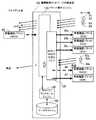
図23は、従来の輻輳制御例を示す図である。図23では、伝送されるパケットを、丸形の図形で示している。網掛けの丸が優先的に伝送すべきパケット(以下、優先パケットという)であり、白抜きの丸がその他のパケットである。 FIG. 23 is a diagram illustrating an example of conventional congestion control. In FIG. 23, the transmitted packet is indicated by a round figure. Shaded circles are packets to be transmitted with priority (hereinafter referred to as priority packets), and white circles are other packets.
第1の状態[ST1]は、輻輳発生状態を示す図である。帯域幅の太い伝送路901から帯域幅の細い伝送路902に大量のパケットが流されて、輻輳が発生している状態を示している。第1の状態では、輻輳制御を行っておらず、パケットの優先度に関わらず、伝送できないパケット(廃棄されるパケット)が発生する。 The first state [ST1] is a diagram showing a congestion occurrence state. A large amount of packets are flown from the transmission line 901 with a large bandwidth to the transmission line 902 with a narrow bandwidth, and congestion occurs. In the first state, congestion control is not performed, and packets that cannot be transmitted (discarded packets) occur regardless of packet priority.
第2の状態[ST2]は、帯域制御によって輻輳を回避した状態である。帯域制御を行うことで、優先パケットに対して所定の帯域幅を確保することができる。これにより、優先パケットは廃棄されずにすむ。 The second state [ST2] is a state where congestion is avoided by bandwidth control. By performing the bandwidth control, a predetermined bandwidth can be secured for the priority packet. As a result, priority packets need not be discarded.
なお、帯域制御以外にも輻輳を制御する技術は存在する。例えば、受信側のノードの受信バッファに受信する余地が無いことでデータの転送に失敗した場合、受信側のノードが行っている他の通信が完了するのを待ってからデータの再送を行う技術がある(特許文献1参照)。 In addition to bandwidth control, there is a technique for controlling congestion. For example, if data transfer fails because there is no room to receive in the reception buffer of the receiving side node, the data is retransmitted after waiting for completion of other communications performed by the receiving side node (See Patent Document 1).
また、データを中継するルータにおいて、輻輳によってバッファに保持できず廃棄されたパケットがある場合、廃棄されたパケットに続いて受信したパケットを順次廃棄する技術がある(特許文献2参照)。 In addition, in a router that relays data, there is a technique for sequentially discarding received packets following a discarded packet when there is a discarded packet that cannot be held in a buffer due to congestion (see Patent Document 2).
このように、輻輳が発生した場合、送信側ノードあるいはパケットを中継するノードにおいて、輻輳が発生したノードやネットワークへのデータ送信を停止し、輻輳状態を緩和させることができる。
しかし、特許文献1,2のように、輻輳状態が解消するまでパケットを廃棄すると、未受信の最初のパケット以降のすべてのパケットの再送処理等、余計なパケットが発生し、ネットワーク経路のリソース有効利用が阻害されてしまう。その結果として輻輳の悪化を促進したり、通信品質が悪化したりすることがある。この問題は、優先度に応じた帯域制御を行った場合にも同様に発生する。 However, as in
図24は、輻輳発生時の通信状況を示す図である。図24には、帯域制御によって確保された通信帯域よりも多くの優先パケットが伝送された場合を示している。
帯域制御によって優先パケット用に帯域を確保したとしても、確保された帯域幅を超える優先パケットが送られてきた場合には輻輳が発生し、一部の優先パケットが廃棄される。輻輳が発生しデータが廃棄されると、受信側の装置からは、廃棄されたデータの前までのデータの受信確認(ACK)パケットが繰り返し送信される。送信側の装置は、同じ内容のACKパケットを三回受け取ると、廃棄されたデータパケット以降のすべてのパケットを再送する。すると、実際のデータパケットよりも多くのパケットが伝送路901を流れることとなり、データ転送の実効値で見た場合の帯域幅は、輻輳によって狭められてしまう。FIG. 24 is a diagram illustrating a communication state when congestion occurs. FIG. 24 shows a case where more priority packets are transmitted than the communication band secured by the band control.
Even if a bandwidth is reserved for priority packets by bandwidth control, if a priority packet exceeding the reserved bandwidth is sent, congestion occurs and some priority packets are discarded. When congestion occurs and data is discarded, the receiving device repeatedly transmits data reception confirmation (ACK) packets before the discarded data. When the transmitting device receives the same ACK packet three times, it retransmits all packets after the discarded data packet. Then, more packets than the actual data packets flow through the transmission path 901, and the bandwidth when viewed in terms of the effective value of data transfer is narrowed due to congestion.
なお、TCP(Transmission Control Protocol)/IP(Internet Protocol)通信では、信頼性のある通信を行う為にパケットの受信確認を行っている。受信確認は、受信側が受信したパケットの受信確認パケットを送信側に送り返すことにより実現されている。この受信確認は、通常のACKを用いる方法の他に、S(Selective)ACK(RFC2018)を用いることがある。 In TCP (Transmission Control Protocol) / IP (Internet Protocol) communication, packet reception confirmation is performed in order to perform reliable communication. The reception confirmation is realized by sending back a reception confirmation packet of the packet received by the reception side to the transmission side. This reception confirmation may use S (Selective) ACK (RFC2018) in addition to a method using normal ACK.
ACKは、TCPヘッダフォーマットのフラグに含まれる情報であり、ACKフラグに「1」が立っていればヘッダ中の受信確認番号が有効となる。受信確認番号は、受信側で正しく受信した連続のパケットの最終パケットのシーケンス番号である。 ACK is information included in a TCP header format flag. If “1” is set in the ACK flag, the reception confirmation number in the header is valid. The reception confirmation number is the sequence number of the last packet of consecutive packets correctly received on the receiving side.
SACKは、TCPのヘッダに追加されたオプションフィールドに設定される情報である。SACKは、ACKで受信確認されたパケットの後で届かない(ロストした)パケットがあり、それ以降のパケットを受信した場合、どのパケットを受信したのかを個別に通知するために利用される。 SACK is information set in an option field added to the TCP header. The SACK is used to individually notify which packet has been received when there is a packet that has not been received (lost) after the packet confirmed to be received by the ACK, and subsequent packets are received.
SACKを用いれば、通信速度などの低下やパケットの無駄な重複再送を伴わずに、失われたパケットの再送が可能である。ただし、輻輳状態が酷くなるとSACKの特徴であるそれらのメリットが有効に機能せず、逆にTCP輻輳回避動作を遅らせて無駄な再送パケットが流れる結果となる。 By using SACK, lost packets can be retransmitted without a decrease in communication speed or the like and unnecessary redundant retransmission of packets. However, when the congestion state becomes severe, those merits that are the characteristics of SACK do not function effectively, and conversely, the TCP congestion avoidance operation is delayed, resulting in the flow of useless retransmission packets.
図25は、SACKを用いたデータ転送例を示す図である。ここで、送信側装置から100番〜102番のパケット910〜912が受信側装置に送られた際に、101番のパケット911が届かなかった(ロストした)ものとする。すると、受信側装置は、100番まで受信したことを示すACKパケット913に、SACKにより102番のパケット912を受信したことを示す情報を付加する。 FIG. 25 is a diagram illustrating an example of data transfer using SACK. Here, it is assumed that when the
送信側装置は、高速のデータ通信を前提としている場合、ACKパケット913を待つことなく、後続のパケットを順次送信する。従って、103番と104番のパケット914,915が順次送信される。すると、受信側装置は、101番のパケット911を受信していないため、100番まで受信したことを示すACKパケット916に、SACKにより102〜104番のパケットを受信したことを示す情報を付加する。 The transmission side apparatus sequentially transmits subsequent packets without waiting for the
その後、同様に、送信側装置から105番と106番のパケット917,918が順次送信されると、受信側装置から、102〜106番のパケットを受信したことを示す情報が付加された、100番まで受信したことを示すACKパケット919が送信される。 Thereafter, similarly, when the 105th and
送信側装置は、ACKパケット913,916,919を受信することで101番のパケット911が届いていないことを認識すると、101番のパケット920を再送する。その後、送信側装置から107番のパケット921が送られると、受信側装置から107番まで受信したことを示すACKの応答パケット922が返される。以後、送信側装置からは、108番のパケット923、109番のパケット924が順次送信される。 When the transmission side apparatus recognizes that the
このようにして、パケットのロストが発生しても、ロストしたパケットのみを再送することができ、無駄なパケットの再送を抑制することができる。
しかしながら、SACKは最大4つの情報しか1パケットで送ることはできないため、輻輳が発生し、ロストするパケットが頻発すると、とびとびで受信したすべてのパケットの情報を受信確認パケットに付加することができない。しかも、SACKは、ACKの代わりにはならない(SACKをもって受信確認としてはいけないと定義されている)。そのため、SACKによって受信側装置に届いていることが認識できたパケットであっても、そのパケットのACKパケットを受け取ることができなければ、いずれ再送する必要がある。In this way, even when a lost packet occurs, only the lost packet can be retransmitted, and unnecessary packet retransmission can be suppressed.
However, since SACK can send only a maximum of four pieces of information in one packet, if congestion occurs and lost packets occur frequently, it is not possible to add information of all packets received in a burst to the reception confirmation packet. Moreover, SACK does not replace ACK (it is defined that SACK should not be acknowledged). For this reason, even if a packet has been recognized as having arrived at the receiving device by SACK, if it cannot receive the ACK packet of that packet, it will need to be retransmitted.
このように、データパケットロストが多発する状況では、SACKを用いたとしても、ロストしたパケットのみの再送ではなく、既に渡されたパケットの重複再送が発生してしまう。 As described above, in a situation where data packet lost occurs frequently, even if SACK is used, not only the lost packet is retransmitted but also a duplicate retransmission of the already delivered packet occurs.
本発明はこのような点に鑑みてなされたものであり、受信側装置へ既に渡されたパケットの重複再送を防止することができる輻輳制御ネットワーク中継装置、および輻輳制御ネットワーク中継方法を提供することを目的とする。 The present invention has been made in view of the above points, and provides a congestion control network relay device and a congestion control network relay method capable of preventing duplicate retransmission of a packet already passed to a reception side device. With the goal.
本発明では上記課題を解決するために、図1に示すような複数の伝送路間のデータを中継する輻輳制御ネットワーク中継装置1が提供される。
受信確認パケット検出手段1aは、複数の伝送路2,3を経由して送受信されるパケットのうち、受信側装置が受信したデータパケット4a,4cの識別番号を送信側装置に対して応答する受信確認パケット5を検出する。受信パケット管理手段1bは、受信確認パケット検出手段1aで検出された受信確認パケット5に基づいて、受信側装置で受信が確認されたデータパケットの識別番号を受信確認情報記憶手段1cに登録する。受信済パケット判断手段1dは、送信側装置から送信されたデータパケットの識別番号と受信確認情報記憶手段1cに格納された識別番号とを比較し、送信側装置から送信されたデータパケット4d,4eが受信側装置で受信済みのデータパケットか否かを判断する。パケット転送手段1eは、受信済パケット判断手段1dで受信済みと判断された場合、送信側装置から送られたデータパケット4eを廃棄し、受信済パケット判断手段1dで未受信と判断された場合、送信側装置から送られたデータパケット4dを受信側装置に転送する。In order to solve the above-described problems, the present invention provides a congestion control
The reception confirmation packet detection means 1a receives the identification number of the
このような輻輳制御ネットワーク中継装置1によれば、受信確認パケット検出手段1aにより、複数の伝送路2,3を経由して送受信されるパケットのうち、受信側装置が受信したデータパケット4a,4cの識別番号を送信側装置に対して応答する受信確認パケット5が検出される。すると、受信パケット管理手段1bにより、受信確認パケット検出手段1aで検出された受信確認パケット5に基づいて、受信側装置で受信が確認されたデータパケットの識別番号が受信確認情報記憶手段1cに登録される。その後、受信済パケット判断手段1dにより、送信側装置から送信されたデータパケット4d,4eの識別番号と受信確認情報記憶手段1cに格納された識別番号とが比較され、送信側装置から送信されたデータパケット4d,4eが受信側装置で受信済みのデータパケットか否かが判断される。そして、パケット転送手段1eにより、受信済パケット判断手段1dで受信済みと判断された場合、送信側装置から送られたデータパケット4eが廃棄され、受信済パケット判断手段1dで未受信と判断された場合、送信側装置から送られたデータパケット4dが受信側装置に転送される。 According to such a congestion control
また、上記課題を解決するために、複数の伝送路間のデータを中継するための輻輳制御ネットワーク中継方法において、受信確認パケット検出手段が、前記複数の伝送路を経由して送受信されるパケットのうち、受信側装置が受信したデータパケットの識別番号を送信側装置に対して応答する受信確認パケットを検出し、受信パケット管理手段が、前記受信確認パケット検出手段で検出された前記受信確認パケットに基づいて、前記受信側装置で受信が確認されたデータパケットの識別番号を受信確認情報記憶手段に登録し、受信済パケット判断手段が、前記送信側装置から送信されたデータパケットの識別番号と前記受信確認情報記憶手段に格納された識別番号とを比較し、前記送信側装置から送信されたデータパケットが前記受信側装置で受信済みのデータパケットか否かを判断し、パケット転送手段が、前記受信済パケット判断手段で受信済みと判断された場合、前記送信側装置から送られたデータパケットを廃棄し、前記受信済パケット判断手段で未受信と判断された場合、前記送信側装置から送られたデータパケットを前記受信側装置に転送する、ことを特徴とする輻輳制御ネットワーク中継方法が提供される。 In order to solve the above-mentioned problem, in a congestion control network relay method for relaying data between a plurality of transmission paths, a reception confirmation packet detection unit is configured to receive packets transmitted and received via the plurality of transmission paths. Among them, a reception confirmation packet that responds to the transmission side device with the identification number of the data packet received by the reception side device is detected, and the reception packet management means detects the reception confirmation packet detected by the reception confirmation packet detection means Based on this, the identification number of the data packet confirmed to be received by the receiving side apparatus is registered in the reception confirmation information storage means, and the received packet judging means is configured to identify the identification number of the data packet transmitted from the transmitting side apparatus and the The identification number stored in the reception confirmation information storage means is compared, and the data packet transmitted from the transmission side device is the reception side device. It is determined whether or not the data packet has been received, and when the packet transfer means determines that the received packet is determined by the received packet determination means, the data packet sent from the transmission side device is discarded, and the received packet A congestion control network relay method is provided, in which when the determination means determines that the packet has not been received, the data packet sent from the transmission side device is transferred to the reception side device.
本発明では、既に受信側装置で受信済のデータパケットが再送された場合、そのデータパケットを廃棄するようにした。これにより、受信側装置との間の伝送路で輻輳が発生した場合に、受信側装置へ既に渡されたパケットが、受信側装置への伝送路に重複再送されることを防止できる。その結果、輻輳が発生した場合の通信効率を向上させることができる。 In the present invention, when a data packet that has already been received by the receiving apparatus is retransmitted, the data packet is discarded. As a result, when congestion occurs on the transmission path to the receiving side apparatus, it is possible to prevent a packet already passed to the receiving side apparatus from being repeatedly retransmitted to the transmission path to the receiving side apparatus. As a result, communication efficiency when congestion occurs can be improved.
以下、本発明の実施の形態を図面を参照して説明する。
図1は、本実施の形態の概略を示す図である。輻輳制御ネットワーク中継装置1は、複数の伝送路2,3間のデータを中継する装置である。なお、図1の例では、伝送路3は、伝送路2よりも通信速度が遅いものとする。また、伝送路2を介して送信側装置が接続されており、伝送路3を介して受信側装置が接続されているものとする。この輻輳制御ネットワーク中継装置1は、受信確認パケット検出手段1aと、受信パケット管理手段1b、受信確認情報記憶手段1c、受信済パケット判断手段1d、およびパケット転送手段1eを有している。Hereinafter, embodiments of the present invention will be described with reference to the drawings.
FIG. 1 is a diagram showing an outline of the present embodiment. The congestion control
受信確認パケット検出手段1aは、複数の伝送路2,3を経由して送受信されるパケットのうち、受信側装置が受信したデータパケット4a,4bの識別番号を送信側装置に対して応答するための受信確認パケット5を検出する。例えば、図1の例では、送信側装置が送信したデータパケット4a,4b,4cのうち、データパケット4a,4cが受信側装置で受信されている。すると、受信側装置からは、データパケット4aの識別番号(100)までの受信を確認する情報(ACK:100)と、データパケット4cの識別番号(102)が受信されたことを示す情報(SACK:102)とが含まれた受信確認パケット5が送信される。 The reception confirmation packet detection means 1a responds to the transmission side apparatus with the identification numbers of the
受信パケット管理手段1bは、受信確認パケット検出手段1aで検出された受信確認パケット5に基づいて、受信側装置で受信が確認されたデータパケットの識別番号を受信確認情報記憶手段1cに登録する。図1の例では、受信パケット管理手段1bは、識別番号(100)までの受信が確認されたことを示す情報(ACK:100)と、識別番号(102)のデータパケット4cが受信されたことを示す情報(SACK:102)とを、受信確認情報5aとして受信確認情報記憶手段1cに格納する。 Based on the reception confirmation packet 5 detected by the reception confirmation packet detection means 1a, the reception packet management means 1b registers the identification number of the data packet confirmed to be received by the reception side device in the reception confirmation information storage means 1c. In the example of FIG. 1, the received packet management means 1b receives the information (ACK: 100) indicating that the reception up to the identification number (100) has been confirmed and the
受信済パケット判断手段1dは、送信側装置から送信されたデータパケットの識別番号と受信確認情報記憶手段1cに格納された識別番号とを比較する。そして、受信済パケット判断手段1dは、送信側装置から送信されたデータパケット4d,4eが受信側装置で受信済みのデータパケットか否かを判断する。図1の例では、データパケット4dの識別番号が101であり、データパケット4eの識別番号は102である。すると、受信済パケット判断手段1cは、データパケット4eに関して受信済みと判断し、データパケット4dに関して、未受信と判断する。 The received
パケット転送手段1eは、受信済パケット判断手段1dで受信済みと判断された場合、送信側装置から送られたデータパケット4eを廃棄する。また、パケット転送手段1eは、受信済パケット判断手段1dで未受信と判断された場合、送信側装置から送られたデータパケット4dを受信側装置に転送する。 The
このような輻輳制御ネットワーク中継装置1によれば、例えば、送信側装置から送信されたデータパケット4a,4b,4c(再送パケットでは無いものとする)が伝送路2を介して入力されると、パケット転送手段1eにより、それらのデータパケット4a,4b,4cが伝送路3へ転送される。このとき、伝送路3で輻輳が発生し、データパケット4bが失われると、受信側装置からは、データパケット4a,4cの受信を示す受信確認パケット5が送信される。 According to such a congestion control
すると、受信確認パケット5が受信確認パケット検出手段1aで検出され、受信パケット管理手段1bによって、受信確認情報5aが受信確認情報記憶手段1cに格納される。なお、受信確認パケット5は、通常通りパケット転送手段1eによって送信側装置へ転送される。 Then, the reception confirmation packet 5 is detected by the reception confirmation packet detection means 1a, and the
その後、送信側装置では、データパケット4bのロストを認識し、データパケット4b以降の各データパケット4d,4eを再送する。再送されたデータパケット4d,4eが輻輳制御ネットワーク中継装置1に入力されると、受信済パケット判断手段1dによって、データパケット4dは未受信であり、データパケット4eは受信済みであることが判断される。すると、パケット転送手段1eは、データパケット4dを受信側装置へ転送し、データパケット4eを廃棄する。 Thereafter, the transmission side apparatus recognizes the lost data packet 4b and retransmits the
これにより、受信側装置との間の伝送路で輻輳が発生した場合に、受信側装置へ既に渡されたパケットが、受信側装置への伝送路に重複再送されることを防止できる。その結果、輻輳が発生した場合の通信効率を向上させることができる。すなわち、輻輳発生や輻輳の度合いを抑制し、輻輳によって発生する品質劣化を抑え、ネットワークリソースの有効利用を促進することができる。 As a result, when congestion occurs on the transmission path to the receiving side apparatus, it is possible to prevent a packet already passed to the receiving side apparatus from being repeatedly retransmitted to the transmission path to the receiving side apparatus. As a result, communication efficiency when congestion occurs can be improved. That is, it is possible to suppress the occurrence of congestion and the degree of congestion, suppress the quality deterioration caused by the congestion, and promote effective use of network resources.
ところで、図1に示した機能は、ネットワークを介して情報通信を行う分野全般に適用可能である。例えば、TCP/IP通信に、図1に示したような機能を適用できる。すなわち、現在のTCP/IP技術は、ブロードバンド環境をはじめとする高速・広帯域ネットワーク環境において、その能力を有効に利用する為に改良されている。しかし、無線経路などの帯域幅の狭い伝送路が存在する場合もある。例えば、有線のネットワークに、無線LAN(Local Area Network)が接続される場合もある。 By the way, the function shown in FIG. 1 can be applied to all fields in which information communication is performed via a network. For example, the function shown in FIG. 1 can be applied to TCP / IP communication. That is, the current TCP / IP technology has been improved in order to effectively use its capabilities in a high-speed / broadband network environment such as a broadband environment. However, there may be a transmission path with a narrow bandwidth such as a wireless path. For example, a wireless local area network (LAN) may be connected to a wired network.
広帯域向けのチューニングでは、データパケットをできるだけ連続して送信することが主眼となるため、輻輳の発生を送信側が認識したときには、輻輳でロストしたパケット以降のパケットも送信されている場合が多い。すると、輻輳の発生によりパケットの再送が生じると、輻輳状態が悪化し、結果的に帯域幅の狭い伝送路の有効利用が妨げられることとなる。そこで、本実施の形態に示す技術を適用し、大容量高速回線と低速回線の接続場所での輻輳制御を行うことで、輻輳の発生を抑制したり、輻輳状態を抑えたりする働きを行うことができる。 In tuning for a wide band, data packets are transmitted continuously as much as possible. Therefore, when the transmission side recognizes the occurrence of congestion, the packets after the packet lost due to congestion are often transmitted. Then, when packet retransmission occurs due to the occurrence of congestion, the congestion state deteriorates, and as a result, effective use of a transmission path with a narrow bandwidth is hindered. Therefore, by applying the technology shown in this embodiment and performing congestion control at the connection place of the high-capacity high-speed line and the low-speed line, the function of suppressing the occurrence of congestion or suppressing the congestion state is performed. Can do.
以下、本実施の形態の詳細を説明する。
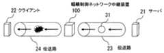
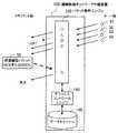
図2は、本実施の形態のシステム構成例を示す図である。輻輳制御ネットワーク中継装置100は、サーバ21とクライアント22とに対して、伝送路23,24を介して接続されている。サーバ21から送信されるパケット31は伝送路23を介して輻輳制御ネットワーク中継装置100に送られる。そして、パケット31は、輻輳制御ネットワーク中継装置100で中継され、伝送路24を介してクライアント22に送られる。Details of the present embodiment will be described below.
FIG. 2 is a diagram illustrating a system configuration example of the present embodiment. The congestion control
伝送路24は、伝送路23よりもデータの伝送速度が遅いものとする。例えば、伝送路23が高速のLANであり、伝送路24がLANよりも通信速度が低いWAN(Wide Area Network)である。 It is assumed that the
このようなネットワークでは、サーバ21から伝送路23経由で送信されたパケット31が、伝送路24上で輻輳を生じさせる場合がある。このように、輻輳制御ネットワーク中継装置100は、輻輳によるパケットロストが発生する可能性がある伝送路の入り口(パケット送信側)に設置される。 In such a network, the
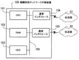
図3は、本実施の形態に用いる輻輳制御ネットワーク中継装置のハードウェア構成例を示す図である。輻輳制御ネットワーク中継装置100は、CPU(Central Processing Unit)101によって装置全体が制御されている。CPU101には、バス106を介してRAM(Random Access Memory)102、ハードディスクドライブ(HDD:Hard Disk Drive)103、および通信インタフェース104,105が接続されている。 FIG. 3 is a diagram illustrating a hardware configuration example of the congestion control network relay device used in the present embodiment. The entire congestion control
RAM102には、CPU101に実行させるOS(Operating System)のプログラムやアプリケーションプログラムの少なくとも一部が一時的に格納される。また、RAM102には、CPU101による処理に必要な各種データが格納される。HDD103には、OSやアプリケーションプログラムが格納される。 The
通信インタフェース104は、伝送路23に接続されている。通信インタフェース104は、伝送路23を介して、他のサーバ21との間でデータの送受信を行う。
通信インタフェース105は、伝送路24に接続されている。通信インタフェース105は、伝送路24を介して、他のクライアント22との間でデータの送受信を行う。The
The
以上のようなハードウェア構成によって、本実施の形態の処理機能を実現することができる。
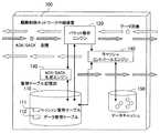
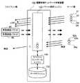
図4は、輻輳制御ネットワーク中継装置の機能を示すブロック図である。輻輳制御ネットワーク中継装置100には、管理テーブル記憶部110,パケット解析エンジン120、ACK/SACK生成エンジン130、キャッシュコントロールエンジン140、およびデータキャッシュ150を有している。With the hardware configuration as described above, the processing functions of the present embodiment can be realized.
FIG. 4 is a block diagram illustrating functions of the congestion control network relay device. The congestion control
管理テーブル記憶部110には、セッション管理テーブル111とデータ管理テーブル112とが格納されている。セッション管理テーブル111には、サーバ21とクライアント22間で確立されるセッションを管理するためのデータが登録される。データ管理テーブル112には、サーバ21とクライアント22間で送受信されるデータを管理するためのデータが登録される。 In the management
パケット解析エンジン120は、中継するパケットの内容を解析する。そして、パケット解析エンジン120は、セッション関連のパケット(SYN,FIN,RSETなど)を受信した場合、セッション管理テーブル111への追加・削除・変更を行う。 The
また、パケット解析エンジン120は、データパケットを受信した場合、セッション管理テーブル111とデータ管理テーブル112とを参照し、以下の処理を行う。パケット解析エンジン120は、データパケットを受信すると、まず、廃棄の可否チェック、キャッシュ要・不要のチェック、セッションテーブルの更新などを行う。その後、パケット解析エンジン120は、チェック結果に応じて、パケットの送出、キャッシュへの収納、キャッシュからデータパケットを出すようにキャッシュコントロールエンジン140への指示などの処理を行う。 Further, when receiving the data packet, the
さらに、パケット解析エンジン120は、ACK/SACKパケットを受信した場合、管理テーブル記憶部110で確認し、ACK/SACK変換の要否を判断する。変換の必要があれば、パケット解析エンジン120は、ACK/SACK生成エンジン130に依頼を行う。 Further, when receiving an ACK / SACK packet, the
ACK/SACK生成エンジン130は、ACKからSACKへの変換や、その逆の変換を行う。また、ACK/SACK生成エンジン130は、再送依頼などの処理を行う。
キャッシュコントロールエンジン140は、データパケットのキャッシュ関連処理を行う。具体的には、キャッシュコントロールエンジン140は、データキャッシュ150へのデータの保存、取り出し、ガベージコレクションなどの処理を行う。The ACK /
The
図5は、セッション管理テーブルのデータ構造例を示す図である。セッション管理テーブル111には、セッション毎のセッション管理情報111a,111b,111c,・・・が登録されている。セッション管理情報111a,111b,111c,・・・は、セッションの識別情報とセッション情報とに大別される。 FIG. 5 is a diagram illustrating an exemplary data structure of the session management table. In the session management table 111,
セッション管理情報111a,111b,111c,・・・には、セッションID(SessID)、送信元アドレス(ScrAddr)、送信元ポート(ScrPort)、宛先アドレス(DstAddr)、宛先ポート(DstPort)が含まれている。 The
セッションIDは、セッションの管理番号である。送信元アドレスは、セッションを用いてデータを送信する送信元装置(例えばサーバ21)のIPアドレスである。送信元ポートは、送信元装置においてセッションで関連づけられたアプリケーションのポート番号である。宛先元アドレスは、セッションを用いてデータを受信する宛先装置(例えばクライアント22)のIPアドレスである。宛先元ポートは、宛先装置においてセッションで関連づけられたアプリケーションのポート番号である。 The session ID is a session management number. The transmission source address is an IP address of a transmission source device (for example, the server 21) that transmits data using a session. The transmission source port is a port number of an application associated in a session in the transmission source device. The destination source address is an IP address of a destination device (for example, the client 22) that receives data using a session. The destination source port is a port number of an application associated with the session in the destination device.
セッション情報には、SACK利用フラグ(SACK)、データパケットの最終到着時刻(DataRcvTime)、ACK,SACKパケットの最終到着時刻(AckRcvTime)、シーケンス番号(SqNo)、ACK番号(ACK)、SACK状況(SACK)、現在の状況(Active, CloseWaitなど)(Status)、再送状態、キャッシュ状態、処理内容、セッション作成情報(SessInfo)、および再送管理情報が含まれている。 The session information includes a SACK usage flag (SACK), a data packet last arrival time (DataRcvTime), an ACK, a last arrival time (AckRcvTime) of a SACK packet, a sequence number (SqNo), an ACK number (ACK), and a SACK status (SACK). ), Current status (Active, CloseWait, etc.) (Status), retransmission status, cache status, processing content, session creation information (SessInfo), and retransmission management information.
データパケットの最終到着時刻は、下り方向に流されるデータパケット(例えば、サーバ21からクライアント22へのデータパケット)が最後に到着した時刻である。
ACK,SACKパケットの最終到着時刻は、上り方向に流されるACKパケットやSACKパケットが最後に到着した時刻である。The final arrival time of the data packet is the time when the data packet (for example, the data packet from the server 21 to the client 22) that flows in the downstream direction arrives last.
The final arrival time of the ACK and SACK packets is the time at which the ACK packet or SACK packet that is sent in the upstream direction arrives last.
シーケンス番号は、上り方向と下り方向とのそれぞれのパケットのシーケンス番号である。
ACK番号は、上り方向と下り方向とのそれぞれのACK番号(ACKによって確認応答がされたシーケンス番号)である。The sequence number is the sequence number of each packet in the uplink direction and the downlink direction.
The ACK number is an ACK number in each of the uplink direction and the downlink direction (sequence number that has been acknowledged by ACK).
SACK状況は、上り方向と下り方向とのそれぞれの、SACKによって通知されたシーケンス番号である。
現在の状況は、上り方向と下り方向との通信状況を表す状態情報である。状態情報としては、例えば、Active(通信中であることを示す)、CloseWait(通信を終了させる時の通信相手からの応答待ちであることを示す)などの情報が記録される。The SACK status is a sequence number notified by SACK in each of the uplink direction and the downlink direction.
The current status is status information indicating the communication status in the uplink direction and the downlink direction. As status information, for example, information such as Active (indicating that communication is in progress), CloseWait (indicating that a communication partner is waiting for a response when communication is terminated), and the like are recorded.
再送状態は、上り方向と下り方向との、パケット再送の発生状況を示す情報である。例えば、再送状態として、パケットの再送が行われたか否かに関する情報が格納される。また、再送状態として、単位時間当たりに送信されたデータパケットの総数と、再送されたデータパケット数とを示す情報を格納することもできる。 The retransmission status is information indicating the occurrence status of packet retransmission in the uplink direction and the downlink direction. For example, information regarding whether or not a packet has been retransmitted is stored as the retransmission state. Further, as the retransmission state, information indicating the total number of data packets transmitted per unit time and the number of retransmitted data packets can be stored.
キャッシュ状態は、上り方向と下り方向とのそれぞれのパケットに関し、キャッシュすべきか否かを示す情報である。
処理内容は、上り方向と下り方向とのそれぞれのパケットに関し、転送するパケットに対して実施する処理の内容が定義されている。例えば、キャッシュの開始条件、キャッシュされたパケットの廃棄条件等が定義されている。The cache state is information indicating whether or not to cache each packet in the upstream direction and the downstream direction.
The content of processing defines the content of processing to be performed on a packet to be transferred with respect to each packet in the uplink direction and the downlink direction. For example, a cache start condition, a cached packet discard condition, and the like are defined.
セッション作成情報は、上り方向と下り方向とに関し、セッションを開始時点から管理しているのか、途中から管理しているのかを示す情報である。すなわち、原則的にはセッションの開始時点から輻輳制御ネットワーク中継装置100でセッションが管理されるが、輻輳制御ネットワーク中継装置100の起動時に既に確立されているセッションがある場合、そのセッションの途中の状態からセッション管理が行われる。 The session creation information is information indicating whether the session is managed from the start time or from the middle with respect to the uplink direction and the downlink direction. That is, in principle, a session is managed by the congestion control
再送管理情報は、上り方向と下り方向とのパケットに関して、再送すべきか否かに関する情報である。
図6は、データ管理テーブルのデータ構造例を示す図である。データ管理テーブル112には、中継した個々のデータを管理するためのデータ管理情報112a,112b,112c,・・・が格納されている。具体的には、データ管理112a,112b,112c,・・・には、データ毎に、セッションID(SessID)、キャッシュでの位置情報、前のパケット、次のパケット、保存日時、及び状況の各情報が格納されている。The retransmission management information is information regarding whether or not to retransmit packets in the uplink and downlink directions.
FIG. 6 is a diagram illustrating an example of the data structure of the data management table. The data management table 112 stores
セッションIDは、セッションの管理番号である。キャッシュでの位置情報は、データキャッシュ150に格納された管理対象データの格納場所を特定する情報である。前のパケットは、同一セッションにおいて管理対象データの前に転送されたパケットに関する情報である。次のパケットは、同一セッションにおいて管理対象データの次に転送される予定のパケットに関する情報である。保存日時は、管理対象データがデータキャッシュ150に格納された日時を示す情報である。状況は、データを格納した際の状況に関する情報である。 The session ID is a session management number. The location information in the cache is information for specifying the storage location of the management target data stored in the
次に、以上のような構成の輻輳制御ネットワーク中継装置100における輻輳制御処理を具体的に説明する。なお、本実施の形態における輻輳制御処理は、重複再送制御処理、データキャッシュを用いた再送応答処理、部分データキャッシュ処理、および受信確認パケットの再送要求への変換処理からなる。 Next, the congestion control processing in the congestion control
まず、重複再送制御処理について説明する。
図7は、重複再送制御処理を示す図である。図7の例では、サーバ21から送られるデータパケット41〜47が、輻輳制御ネットワーク中継装置100で中継され、クライアント22に送信される場合を想定している。First, the duplicate retransmission control process will be described.
FIG. 7 is a diagram illustrating the duplicate retransmission control process. In the example of FIG. 7, it is assumed that
パケット解析エンジン120は、通過するトラフィックの受信確認パケット49a(ACKやSACK)の受信確認番号や受信範囲を記憶し、重複再送パケットの廃棄を行う。具体的には、パケット解析エンジン120は、通過するパケット41〜47に対する受信確認パケット49(ACKやSACK)に記述されている受信確認番号や受信済み範囲の情報を読み出し、セッション管理テーブル111に、セッション管理情報として格納する。同時に、パケット解析エンジン120は、クライアント22側から受信した受信確認パケット49をサーバ21側に転送する。 The
ここで、サーバ21側で輻輳の発生を認識するとパケットの再送が行われる。図7の例では、パケット42の再送パケット42a、パケット43の再送パケット43a、パケット46の再送パケット46aがサーバ21から送信されている。なお、一般に、パケットの再送を行う場合、サーバ21は、単位時間当たりのデータ量を少なくして、再度の輻輳の発生を防止する。 Here, when the occurrence of congestion is recognized on the server 21 side, the packet is retransmitted. In the example of FIG. 7, the
パケット解析エンジン120は、セッション管理テーブル111に格納されたセッション管理情報をもとに、重複送信されるデータパケットを検出する。重複送信されるデータパケットは、パケット解析エンジン120において廃棄される。図7の例では、受信確認パケット49によって、パケット43がクライアント22で受信されていることが判明しているものとする。この場合、パケット解析エンジン120は、パケット43の再送パケット43aを廃棄し、その他の再送パケット42a,46aは、クライアント22側の伝送路24に転送する。 The
その後、後続のパケット48がサーバ21側から送られると、パケット解析エンジン120は、そのパケット48をクライアント22側の伝送路24に転送する。
以下、重複再送制御のためにパケット解析エンジン120で実行する処理の手順を詳細に説明する。Thereafter, when the
Hereinafter, a procedure of processing executed by the
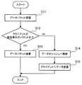
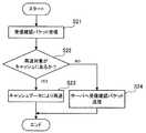
図8は、重複再送制御処理の手順を示すフローチャートである。以下、図8に示す処理をステップ番号に沿って説明する。
[ステップS11]パケット解析エンジン120は、サーバ21側の伝送路23を介してデータパケットを受信する。FIG. 8 is a flowchart showing the procedure of the duplicate retransmission control process. In the following, the process illustrated in FIG. 8 will be described in order of step number.
[Step S11] The
[ステップS12]パケット解析エンジン120は、クライアント22が受信済みのパケットか否かを判定する。具体的には、パケット解析エンジン120は、セッション管理テーブル111を参照し、受信したデータパケットに対応するセッションのセッション情報から、ACK番号やSACK状況に関する情報を抽出し、既にクライアント22で受信しているパケットのシーケンス番号を判断する。そして、パケット解析エンジン120は、受信したデータパケットのシーケンス番号に相当するパケットが、既にクライアント22で受信されているか否かを判断する。 [Step S12] The
クライアント22で受信済みのパケットの場合、処理がステップS13に進められる。クライアント22で未受信のパケットの場合、処理がステップS14に進められる。
[ステップS13]パケット解析エンジン120は、受信したデータパケットが、クライアント22で受信済みのパケットの場合、データパケットを廃棄する。その後、処理が終了する。If the packet has been received by the client 22, the process proceeds to step S13. If the packet has not been received by the client 22, the process proceeds to step S14.
[Step S13] If the received data packet is a packet that has already been received by the client 22, the
[ステップS14]パケット解析エンジン120は、受信したデータパケットが、クライアント22で未受信のパケットの場合、そのパケット内のデータをデータキャッシュ150へ格納する。 [Step S <b> 14] If the received data packet is a packet not received by the client 22, the
[ステップS15]パケット解析エンジン120は、クライアント22へデータを送信し、処理を終了する。
このように、パケット解析エンジン120は、クライアント22からの受信応答パケット(ACKやSACK)を受信すると、ACKで示される受信済みパケットのシーケンス番号や、SACKで示されるシーケンス番号の範囲をセッション管理テーブル111に記録するようにした。そして、パケット解析エンジン120は、セッション管理テーブル111を用いてクライアント22で受信したパケットのシーケンス番号を管理することで、既にクライアント22で受信済みのパケット(既に受信応答が返されているパケット)を輻輳制御ネットワーク中継装置100で廃棄することができる。[Step S15] The
As described above, when receiving the reception response packet (ACK or SACK) from the client 22, the
なお、パケット解析エンジン120は、ACK/SACK生成エンジン130に対して、クライアント22の代わりにACKやSACKの受信確認パケットの送信を依頼することができる。例えば、クライアント22からの受信確認パケットをパケット解析エンジン120では受信しているが、その受信確認パケットがサーバ21に到達する前にロストする場合もある。そこで、パケット解析エンジン120は、クライアント22から受信確認パケットで受信が確認されたパケットがサーバ21から再送された場合、そのパケットに応じたACKまたはSACKの送信をACK/SACK生成エンジン130に依頼する。すると、ACK/SACK生成エンジン130がACKまたはSACKの受信確認パケットを生成し、サーバ21に送信する。 The
なお、ACK/SACK生成エンジン130は、セッション管理テーブル111のセッション情報内のSACKフラグを参照することで、そのセッションでSACKが利用できるか否かを判断することができる。SACKが利用できない場合、ACK/SACK生成エンジン130は、ACKの受信確認パケットを生成する。 The ACK /
また、SACKが利用できる場合、ACK/SACK生成エンジン130は、SACKを利用すべきか否かを判断する。SACKを利用すべき場合とは、ロストしたパケットの後続のパケットがクライアント22で受信されている場合である。ACK/SACK生成エンジン130は、SACKを利用すべき場合は、SACKの情報を含むACKの受信確認パケットを生成する。SACKを利用する必要が無い場合は、ACKの受信確認パケットを生成する。 When SACK can be used, the ACK /
なお、パケット解析エンジン120は、受信側からのACKやSACKで確認できている以上のACKやSACKの送信を、ACK/SACK生成エンジン130に依頼することはない。 Note that the
次に、輻輳制御ネットワーク中継装置100によるデータキャッシュ処理について説明する。輻輳制御ネットワーク中継装置100は、通過するパケットをキャッシュすることで、送信元に代わって再送応答を行うことができる。 Next, data cache processing by the congestion control
図9は、データキャッシュを用いた再送応答処理を示す図である。輻輳制御ネットワーク中継装置100内のパケット解析エンジン120は、サーバ21からパケット51〜54を受信すると、そのパケット51〜54をクライアント22側に転送する。このとき、パケット解析エンジン120は、セッション管理テーブル111を参照し、受信済みのパケットか否かを判定する。受信済みのパケットであれば、パケット解析エンジン120は、受信したパケットを廃棄する。未受信のパケットであれば、パケット解析エンジン120は、キャッシュコントロールエンジン140を介して、そのパケット内のデータをデータキャッシュ150に格納し、受信したパケットをクライアント22に送信する。 FIG. 9 is a diagram illustrating retransmission response processing using a data cache. When the
ここで、パケット52がロストした場合を想定する。この場合、クライアント22からは、パケット51までのACKに、パケット53、54の受信を示すSACKを付加した受信確認パケット55が送信される。 Here, it is assumed that the
この受信確認パケット55を受信したパケット解析エンジン120は、キャッシュコントロールエンジン140を介して、パケット52のデータをデータキャッシュ150から取得する。そして、パケット解析エンジン120は、取得したデータを有するパケットをクライアント22に再送する。 The
その後、パケット解析エンジン120は、サーバ21からパケット52の再送があった場合は、その再送パケットを廃棄する。
なお、パケット解析エンジン120は、クライアント22側からのACKやSACKで確認できている以上のACKやSACKは、サーバ21に送信しない。すなわち、パケット解析エンジン120においてクライアント22に再送を行った場合でも、パケット解析エンジン120は、クライアント22からの再送されたパケットに応じた受信確認パケットの受信前に、再送されたパケットの受信確認パケットをサーバ21に出力することはない。Thereafter, when the
Note that the
なお、輻輳制御ネットワーク中継装置100がサーバ21からデータパケットを受信した際の処理は、図8に示したとおりである。以下、クライアント22からSACKの受信確認パケットを受信したときのパケット解析エンジン120のパケット再送処理の手順を説明する。 The processing when the congestion control
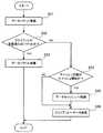
図10は、パケット再送処理の手順を示すフローチャートである。以下、図10に示す処理をステップ番号に沿って説明する。
[ステップS21]パケット解析エンジン120は、クライアント22からのACKまたはSACKの受信確認パケットを受信する。FIG. 10 is a flowchart showing the procedure of packet retransmission processing. In the following, the process illustrated in FIG. 10 will be described in order of step number.
[Step S21] The
[ステップS22]パケット解析エンジン120は、再送対象のパケットがデータキャッシュ150に格納されているか否かを判断する。具体的には、パケット解析エンジン120は、セッション管理テーブル111を参照し、受信確認パケットで未受信としていながら、既にクライアント22に対して送信しているパケットを再送対象とする。そして、パケット解析エンジン120は、再送対象のパケットがデータキャッシュ150に格納されているか否かをキャッシュコントロールエンジン140に問い合わせる。すると、キャッシュコントロールエンジン140は、再送対象のパケットのデータがデータキャッシュ150に格納されている場合、そのデータをパケット解析エンジン120に渡す。また、キャッシュコントロールエンジン140は、再送対象のパケットのデータがデータキャッシュ150に格納されていない場合、その旨をパケット解析エンジン120に通知する。 [Step S22] The
再送対象がデータキャッシュ150にある場合、処理がステップS23に進められる。再送対象がデータキャッシュ150に無い場合、処理がステップS24に進められる。
[ステップS23]パケット解析エンジン120は、キャッシュコントロールエンジン140から受け取ったデータから再送パケットを生成し、その再送パケットをクライアント22に対して送信する。その後、処理が終了する。If the retransmission target is in the
[Step S23] The
[ステップS24]パケット解析エンジン120は、ステップS21で受信した受信確認パケットを、サーバ21へ送信する。その後、処理が終了する。
このようにして、輻輳制御ネットワーク中継装置100によって、サーバ21に代わって、パケットの再送を行うことができる。[Step S24] The
In this way, the congestion control
なお、図9、図10に示した例は、常時データキャッシュを行うものであるが、必要に応じてキャッシュ処理の実施の有無を切り替えることができる。例えば、輻輳制御ネットワーク中継装置100は、SACK状況から、伝送路の品質を判断し、抜けが多くなってきたらデータキャッシュを開始する。 The examples shown in FIGS. 9 and 10 perform data caching at all times, but it is possible to switch whether or not to perform cache processing as necessary. For example, the congestion control
図11は、部分データキャッシュ処理を示す図である。輻輳制御ネットワーク中継装置100内のパケット解析エンジン120は、サーバ21からパケット61〜64を受信すると、そのパケット61〜64をクライアント22側に転送する。 FIG. 11 is a diagram showing the partial data cache processing. When the
このとき、パケット解析エンジン120は、セッション管理テーブル111のキャッシュ状態を参照し、キャッシュの要否を判断する。クライアント22側の伝送路24で輻輳が発生していなければ、キャッシュ状態においてキャッシュ停止と設定されている。 At this time, the
図11の例では、パケット61〜64を輻輳制御ネットワーク中継装置100が受信した時点では、輻輳が発生していないものとする。この場合、パケット61〜64のキャッシュは行われない。その後、パケット61〜64がクライアント22側の伝送路24を伝送中に輻輳が発生し、例えば、パケット62がロストしたものとする。 In the example of FIG. 11, it is assumed that congestion does not occur when the congestion control
この場合、クライアント22からは、パケット61までの受信を確認するACKの受信確認パケット65と、パケット61まで及びパケット63〜65の受信を確認するSACKの受信確認パケット66とが出力される。受信確認パケット65,66は、パケット解析エンジン120によってサーバ21へ転送される。 In this case, the client 22 outputs an ACK
このときパケット解析エンジン120は、受信確認パケット65,66を解析し、伝送路24での輻輳の発生を認識する。輻輳の発生を認識したパケット解析エンジン120は、セッション管理テーブル111にアクセスし、キャッシュ状態をキャッシュ開始に変更する。 At this time, the
その後、サーバ21から再送パケット62a,63a,64aが送信されると、パケット解析エンジン120は、クライアント22で受信できていないパケット62に対する再送パケット62aを、クライアント22側に再送する。なお、パケット解析エンジン120は、既に受信確認が行われている再送パケット63a,64aは廃棄する。また、パケット解析エンジン120は、キャッシュコントロールエンジン140を介して、再送パケット62a,63a,64aに含まれるデータをデータキャッシュ150に格納する。 Thereafter, when
このように、輻輳制御ネットワーク中継装置100は、SACK状況から伝送路の品質を判断し、抜けが多くなってきたら、データキャッシュ生成を開始することができる。また、輻輳制御ネットワーク中継装置100は、早めの再送要求をサーバ21に対して行い、キャッシュ構築を早めることもできる。 In this way, the congestion control
これにより、通信品質の良い状態(輻輳が発生していない状態)でのキャッシュの必要がなくなる。
図12は、伝送品質判断処理の手順を示すフローチャートである。以下、図12に示す処理をステップ番号に沿って説明する。This eliminates the need for a cache in a state with good communication quality (a state in which congestion has not occurred).
FIG. 12 is a flowchart illustrating a procedure of transmission quality determination processing. In the following, the process illustrated in FIG. 12 will be described in order of step number.
[ステップS31]パケット解析エンジン120は、クライアント22からACKまたはSACKの受信確認パケットを受信する。
[ステップS32]パケット解析エンジン120は、クライアント22側の伝送路24の通信品質を判断する。例えば、パケット解析エンジン120は、再送発生頻度が予め設定された閾値を超えているか否かにより通信品質を判断できる。[Step S31] The
[Step S32] The
[ステップS33]パケット解析エンジン120は、通信の品質が悪いと判断された場合、処理をステップS34に進め、通信の品質が良好と判断された場合、処理をステップS36に進める。 [Step S33] If the
[ステップS34]パケット解析エンジン120は、通信品質が悪化している場合、サーバ21からのパケットのキャッシュ処理を実行中か否かを判断する。キャッシュ処理を実行中であれば、処理がステップS38に進められる。キャッシュ処理を実行中でなければ、処理がステップS35に進められる。 [Step S34] When the communication quality is deteriorated, the
[ステップS35]パケット解析エンジン120は、セッション管理テーブル111のキャッシュ状態をキャッシュ開始に設定する。その後、処理がステップS38に進められる。 [Step S35] The
[ステップS36]パケット解析エンジン120は、通信品質が良好な場合、サーバ21からのパケットのキャッシュ処理を実行中か否かを判断する。キャッシュ処理を実行中であれば、処理がステップS37に進められる。キャッシュ処理を実行中でなければ、処理がステップS38に進められる。 [Step S36] When the communication quality is good, the
[ステップS37]パケット解析エンジン120は、セッション管理テーブル111のキャッシュ状態をキャッシュ停止に設定する。
[ステップS38]パケット解析エンジン120は、再送対象のパケットがデータキャッシュ150に格納されているか否かを判断する。再送対象がデータキャッシュ150にある場合、処理がステップS39に進められる。再送対象がデータキャッシュ150に無い場合、処理がステップS40に進められる。[Step S37] The
[Step S38] The
[ステップS39]パケット解析エンジン120は、キャッシュコントロールエンジン140から受け取ったデータから再送パケットを生成し、その再送パケットをクライアント22に対して送信する。その後、処理が終了する。 [Step S39] The
[ステップS40]パケット解析エンジン120は、ステップS31で受信した受信確認パケットを、サーバ21へ送信する。その後、処理が終了する。
このようにして、通信品質に応じて、データキャッシュの有無を切り替えることができる。[Step S <b> 40] The
In this way, the presence or absence of the data cache can be switched according to the communication quality.
図13は、部分データキャッシュの処理手順を示すフローチャートである。以下、図13に示す処理をステップ番号に沿って説明する。
[ステップS51]パケット解析エンジン120は、サーバ21側の伝送路23を介してデータパケットを受信する。FIG. 13 is a flowchart showing the processing procedure of the partial data cache. In the following, the process illustrated in FIG. 13 will be described in order of step number.
[Step S51] The
[ステップS52]パケット解析エンジン120は、クライアント22が受信済みのパケットか否かを判定する。クライアント22で受信済みのパケットの場合、処理がステップS53に進められる。クライアント22で未受信のパケットの場合、処理がステップS54に進められる。 [Step S52] The
[ステップS53]パケット解析エンジン120は、受信したデータパケットが、クライアント22で受信済みのパケットの場合、データパケットを廃棄する。その後、処理が終了する。 [Step S53] If the received data packet is a packet that has been received by the client 22, the
[ステップS54]パケット解析エンジン120は、セッション管理テーブル111のキャッシュ状態を参照し、キャッシュ開始と設定されているか否かを判定する。キャッシュ開始と設定されていれば、処理がステップS55に進められる。キャッシュ停止と設定されていれば、処理がステップS56に進められる。 [Step S54] The
[ステップS55]パケット解析エンジン120は、受信したデータパケットが、クライアント22で未受信のパケットの場合、そのパケット内のデータをデータキャッシュ150へ格納する。 [Step S55] If the received data packet is a packet not received by the client 22, the
[ステップS56]パケット解析エンジン120は、クライアント22へデータを送信し、処理を終了する。
このように、輻輳が発生した場合にのみキャッシュ処理を行うようにすることができる。これにより、無駄なデータのキャッシュを行わずに済み、輻輳制御ネットワーク中継装置100のHDD等の記憶媒体を有効利用できると共に、輻輳制御ネットワーク中継装置100の処理付加を軽減できる。[Step S56] The
In this way, cache processing can be performed only when congestion occurs. As a result, it is not necessary to cache useless data, the storage medium such as the HDD of the congestion control
次に、クライアント22から送られたSACKの受信確認パケットを再送要求(受信確認パケット×3)に変換する処理について説明する。輻輳制御ネットワーク中継装置100は、SACKを含む受信確認パケットを通常のACKの受信核にパケットに変換し、送信元に対して通常再送を要求することができる。例えば、輻輳制御ネットワーク中継装置100は、経路の通信状態を考慮して、SACKによる部分再送よりも、TCP輻輳制御を伴うACKによる再送が適していると判断した場合、受信側から送信されるSACKパケットを、再送を示すACKパケット(ACK×3)に変換して、サーバ21へ送信する。 Next, processing for converting the SACK reception confirmation packet sent from the client 22 into a retransmission request (reception confirmation packet × 3) will be described. The congestion control
図14は、受信確認パケットから再送要求への変換処理を示す図である。輻輳制御ネットワーク中継装置100にサーバ21側からパケット71〜78が送られると、パケット解析エンジン120を介して、そのパケット71〜78がクライアント22側に転送される。このとき、とびとびの複数のパケットがロストすると、クライアント22からは、SACKの情報を含む複数の受信確認パケット79,80が出力される。 FIG. 14 is a diagram illustrating a conversion process from a reception confirmation packet to a retransmission request. When
パケット解析エンジン120は、受信確認パケット79,80を解析し、クライアント22側の伝送路24での通信状態を判断する。そして、パケット解析エンジン120は、伝送路24でのパケットロストが多量であり、SACKによる部分再送よりも、TCP輻輳制御を伴うACKによる再送が適していると判断した場合、ACK/SACK生成エンジン130に再送要求の送信を依頼する。すると、ACK/SACK生成エンジン130は、サーバ21側に同じ内容の3つの受信確認パケット81,82,83を連続して送信する。 The
3つの受信確認パケット81,82,83がサーバ21に到達すると、サーバ21は、輻輳の発生を認識し、ACKによって受信が確認されたパケット以降のすべてのパケットを、単位時間当たりのデータ量を減らして再送する。 When the three
図15は、受信確認パケット変換処理の手順を示すフローチャートである。以下、図15に示す処理をステップ番号に沿って説明する。
[ステップS61]パケット解析エンジン120は、SACKを含む受信確認パケットを受信する。FIG. 15 is a flowchart showing the procedure of the reception confirmation packet conversion process. In the following, the process illustrated in FIG. 15 will be described in order of step number.
[Step S61] The
[ステップS62]パケット解析エンジン120は、クライアント22側の伝送路24の通信品質を判断する。例えば、パケット解析エンジン120は、再送発生頻度が予め設定された閾値を超えているか否かにより通信品質を判断できる。 [Step S62] The
[ステップS63]パケット解析エンジン120は、通信の品質が悪いと判断された場合、処理をステップS64に進め、通信の品質が良好と判断された場合、処理をステップS66に進める。 [Step S63] The
[ステップS64]パケット解析エンジン120は、通信品質が悪い場合、ステップS61で受信した受信確認パケットを廃棄する。
[ステップS65]パケット解析エンジン120は、ACK/SACK生成エンジン130に対して、ACKパケット×3の生成を依頼する。すると、ACK/SACK生成エンジン130は、ACKの受信確認パケットを3つ生成し、サーバ21に対して送信する。その後、処理が終了する。[Step S64] If the communication quality is poor, the
[Step S65] The
[ステップS66]パケット解析エンジン120は、通信品質が良好な場合、ステップS61で受信した受信確認パケットをサーバ21に送信する。その後、処理が終了する。
このようにして、SACKの受信確認パケットを、パケットの再送信を要求するパケット(ACKの受信確認パケット×3)に変換して、転送することができる。その結果、通信品質が劣悪であり、パケットのロストが頻発する場合には、サーバ21に対してパケットの再送信を促すことができる。このようなパケットの再送信を示すパケットを受け取ったサーバ21では、クライアント22までに劣悪な通信品質の伝送路が存在することを認識できる。その場合、サーバ21は、送信するパケットの単位時間当たりのデータ量を減らして、パケットの再送信を行うことができる。単位時間当たりのデータ量を減らすことで、劣悪な通信品質の伝送路でもパケットをロストすることなく、クライアント22に伝送させることができる。[Step S66] When the communication quality is good, the
In this manner, the SACK reception confirmation packet can be converted into a packet requesting retransmission of the packet (ACK reception confirmation packet × 3) and transferred. As a result, when the communication quality is poor and the packet is lost frequently, the server 21 can be urged to retransmit the packet. The server 21 that has received such a packet indicating retransmission of the packet can recognize that there is a transmission path with poor communication quality up to the client 22. In that case, the server 21 can retransmit the packet by reducing the amount of data per unit time of the packet to be transmitted. By reducing the amount of data per unit time, the packet can be transmitted to the client 22 without being lost even on a transmission path with poor communication quality.
なお、受信確認パケットの変換処理は、部分データキャッシュ処理と同時に行うこともできる。その場合、輻輳制御ネットワーク中継装置100は、SACK情報に基づいて、ロストパケットが多くなったと判断すると、それ以降のデータをキャッシュすると共に、報告されたSACK範囲が多くあり、キャッシュに存在しないものも多い場合は、再送要求(ACKパケット×3)を行って輻輳状態を解消させ、データキャッシュを早めに完了させる。 Note that the conversion processing of the reception confirmation packet can be performed simultaneously with the partial data cache processing. In that case, when the congestion control
図16は、受信確認パケット変換処理と部分データキャッシュ処理とを組み合わせた例を示す図である。輻輳制御ネットワーク中継装置100にサーバ21側からパケット91〜94が送られると、パケット解析エンジン120を介して、そのパケット91〜94がクライアント22側に転送される。このとき、その中のあるパケットがロストすると、クライアント22からは、SACKの情報を含む複数の受信確認パケット95が出力される。 FIG. 16 is a diagram illustrating an example in which the reception confirmation packet conversion process and the partial data cache process are combined. When
パケット解析エンジン120は、受信確認パケット95を解析し、クライアント22側の伝送路24での通信状態を判断する。そして、パケット解析エンジン120は、伝送路24でのパケットロストが多量であり、SACKによる部分再送よりも、TCP輻輳制御を伴うACKによる再送が適していると判断した場合、ACK/SACK生成エンジン130に再送要求の送信を依頼する。すると、ACK/SACK生成エンジン130は、サーバ21側に同じ内容の3つの受信確認パケット95a,95b,95cを連続して送信する。 The
3つの受信確認パケット95a,95b,95cがサーバ21に到達すると、サーバ21は、輻輳の発生を認識する。そして、サーバ21は、ACKによって受信が確認されたパケット以降のすべてのパケットの内容を、単位時間当たりのデータ量を減らした再送パケット92a,93a,94aを送信する。 When the three
パケット解析エンジン120は、再送パケット92a,93a,94aを受け取ると、クライアント22で受信できていないパケット92に対する再送パケット92aを、クライアント22側に再送する。なお、パケット解析エンジン120は、既に受信確認が行われている再送パケット93a,94aは廃棄する。また、パケット解析エンジン120は、キャッシュコントロールエンジン140を介して、再送パケット92a,93a,94aに含まれるデータをデータキャッシュ150に格納する。クライアント22で受信が確認されていないパケット92に対する再送パケット92aのみをクライアント22に送信する。 When the
そのとき、パケット解析エンジン120は、ACK/SACK生成エンジン130を介して、受信側からのACKやSACKで確認できているパケットの受信確認パケット96,97をサーバ21に対して送信することもできる。 At that time, the
[輻輳状態に応じた輻輳制御処理の組み合わせ例]
なお、図16に示したような処理の組み合わせ以外にも、以上説明した各処理(輻輳制御処理は、重複再送制御処理、データキャッシュを用いた再送応答処理、部分データキャッシュ処理、および受信確認パケットの変換処理)を組み合わせて実行することができる。例えば、目的(品質重視、速度重視など)輻輳状態や受信側状況、ネットワーク環境を判断して、各処理を組み合わせて輻輳制御を行う。そのような処理を実行するのかは、ユーザが輻輳制御ネットワーク中継装置100に対して予め設定する。[Combination example of congestion control processing according to the congestion state]
In addition to the combination of processes shown in FIG. 16, the above-described processes (congestion control process includes duplicate retransmission control process, retransmission response process using data cache, partial data cache process, and reception confirmation packet) Can be executed in combination. For example, the congestion state, the receiving side situation, and the network environment are judged (concentration on quality, importance on speed, etc.), and congestion control is performed by combining each processing. Whether or not to execute such processing is set in advance by the user in the congestion control
具体的には、輻輳状態に応じて輻輳制御の内容を切り替える場合、初期状態(輻輳が発生していない)では、輻輳制御は行わない。中期(輻輳の発生が確認された後)は、重複再送制御処理を開始する。末期(パケットロストが多発した場合)は、データキャッシュを用いた再送応答処理と、受信確認パケットの変換処理(早めの再送要求)とを組み合わせて実行する。 Specifically, when switching the content of the congestion control according to the congestion state, the congestion control is not performed in the initial state (no congestion has occurred). In the middle period (after the occurrence of congestion is confirmed), duplicate retransmission control processing is started. In the last stage (when packet loss occurs frequently), a retransmission response process using a data cache and a conversion process of an acknowledgment packet (early retransmission request) are executed in combination.
また、SACK状況に応じて輻輳制御の内容を切り替える場合、SACKを含む受信確認パケットがまばら(単位時間当たりの発生数が閾値未満)の場合、輻輳制御は行わない。SACKを含む受信確認パケットが多発(単位時間当たりの発生数が閾値以上)した場合、データキャッシュを用いた再送応答処理と、受信確認パケットの変換処理(早めの再送要求)とを組み合わせて実行する。 Also, when switching the content of congestion control according to the SACK status, if the reception confirmation packet including SACK is sparse (the number of occurrences per unit time is less than the threshold), the congestion control is not performed. When there are many reception confirmation packets including SACK (the number of occurrences per unit time is greater than or equal to the threshold), the retransmission response processing using the data cache and the conversion processing of the reception confirmation packet (early retransmission request) are executed in combination. .
[輻輳状態の判定方式の例]
輻輳状態の判定方式としては、次のような方法が考えられる。例えば、RTT(ラウンドトリップタイム)を用いる方法がある。RTTは、あるデータを送ってから、相手の確認応答が戻ってくるまでにかかる時間である。RTTを用いる方法では、送信したデータパケットに対するACKの応答時間(RTT)の閾値をユーザが予め設定し、パケット解析エンジン120は、RTTが閾値を超えた場合、輻輳状態にあると判断する。[Example of congestion status judgment method]
As a method for determining the congestion state, the following method can be considered. For example, there is a method using RTT (round trip time). RTT is the time taken from sending certain data until the other party's confirmation response is returned. In the method using RTT, a user sets a threshold value of an ACK response time (RTT) for a transmitted data packet in advance, and the
また、再送率で輻輳状態を判定することもできる。再送率は、単位時間当たりのデータパケットに対する再送要求数の比率である。再送率の閾値をユーザが予め設定し、パケット解析エンジン120は、再送率が閾値を超えた場合、輻輳状態にあると判断する。 Also, the congestion state can be determined by the retransmission rate. The retransmission rate is the ratio of the number of retransmission requests to the data packet per unit time. A user sets a threshold value for a retransmission rate in advance, and the
[SACK状況の判定例]
通過パケットに対する抜け(クライアント22で受信確認がされていないパケット)の比率の閾値をユーザが設定する。パケット解析エンジン120は、SACK情報に基づいて、通過パケットに対するロストしたパケットの比率を計算し、予め設定された閾値よりもパケットの抜けが多ければ、パケットのロストが多発していると判定する。[Judgment example of SACK status]
The user sets a threshold value for the ratio of missing packets (packets that have not been acknowledged by the client 22) to passing packets. The
なお、輻輳制御ネットワーク中継装置100は、セッション管理テーブル111のガベージコレクション機能を有している。また、キャッシュコントロールエンジン140は、データキャッシュ150からの再送確認済みのデータの削除機能を有している。 Note that the congestion control
さらに、キャッシュコントロールエンジン140は、データキャッシュ150から、途中で終了したセッションのデータを廃棄する機能も有している。例えば、キャッシュコントロールエンジン140は、データ通信が途絶えてから一定時間経過した場合、セッションが終了したものと判断する。また、キャッシュコントロールエンジン140は、同じクライアントから新たなセッションが開始された場合に、もとのセッションが終了したものと判断してもよい。 Further, the
[実施の形態の効果]
上記実施の形態に示すように、輻輳が発生した場合に無駄な再送パケットを輻輳制御ネットワーク中継装置100で廃棄することにより、クライアント22側の伝送路24の有効通信率を向上させることができる。ここで、有効通信率とは、送信されたパケットのうちの有効通信パケットの占める割合である。有効通信パケットとは、アプリケーションで有効に利用されたパケットである。再送などによる重複パケットや通信が最後まで完了せずに、やり取りされたにも関わらずアプリケーションで利用されなかったパケットは、無効通信パケットである。[Effect of the embodiment]
As shown in the above embodiment, when congestion occurs, useless retransmission packets are discarded by the congestion control
例えば、1セッションに10パケットのデータをやり取りする通信の場合、10パケットのみで通信が完了した場合には、有効利用率=100%=10(アプリで利用したパケット)/10(全パケット)となる。 For example, in the case of communication in which 10 packets of data are exchanged in one session, when communication is completed with only 10 packets, the effective utilization rate = 100% = 10 (packets used by the application) / 10 (all packets). Become.
5パケットの再送が発生し、合計15パケットやり取りした場合には、有効利用率=66.7%=10(アプリで利用したパケット)/15(全パケット)となる。
5パケット目でエラーなどにより通信が終了した場合には、有効利用率=0%=0(アプリで利用したパケット)/5(全パケット)となる。When retransmission of 5 packets occurs and a total of 15 packets are exchanged, the effective utilization rate = 66.7% = 10 (packets used by the application) / 15 (all packets).
When communication ends due to an error or the like at the fifth packet, the effective utilization rate = 0% = 0 (packets used by the application) / 5 (all packets).
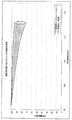
図17は、過負荷状態におけるリンクの有効利用率を示すグラフである。このグラフは、帯域幅100Mbpsの伝送路にその帯域幅を上回るパケットを印加した時に、その伝送路を流れるパケットの全通信パケット中の有効通信パケットの比率をグラフ化したものである。このグラフでは、横軸に印可付加(Mbps)を取り、縦軸に有効通信率(%)を取っている。 FIG. 17 is a graph showing an effective utilization rate of a link in an overload state. This graph is a graph of the ratio of effective communication packets to all communication packets of packets flowing through the transmission path when a packet exceeding the bandwidth is applied to the transmission path with a bandwidth of 100 Mbps. In this graph, the horizontal axis represents applied addition (Mbps), and the vertical axis represents effective communication rate (%).
このグラフには、本実施の形態による輻輳制御をおこなった場合と、輻輳制御を行わなかった場合とについて、単位時間あたりの総パケット数と、成功セッション数×1セッションでやり取りされるパケット数から計算をして作成している。グラフ中、丸印で示されているのが輻輳制御を行った場合の計算値であり、ばつ印で示されているのが輻輳制御を行わなかった場合の計算値である。 This graph shows the total number of packets per unit time and the number of packets exchanged in one session when the congestion control is performed according to this embodiment and when the congestion control is not performed. Created by calculation. In the graph, a circle indicates a calculated value when the congestion control is performed, and a bullet indicates a calculated value when the congestion control is not performed.
なお、本実施の形態を適用した場合のシミュレーションは、輻輳制御ネットワーク中継装置100において廃棄されるパケットを求め、有効通信比率を計算したものである。
このように、図17のグラフで示されるように、本実施の形態によれば重複パケットの通過を防ぐことができることにより、伝送路の有効利用が可能となる。しかも、伝送路が有効に利用されることで、輻輳発生頻度及び輻輳の度合いも低下する。Note that the simulation in the case of applying the present embodiment is a calculation of the effective communication ratio by obtaining packets discarded in the congestion control
Thus, as shown in the graph of FIG. 17, according to the present embodiment, it is possible to prevent the passage of duplicate packets, thereby enabling effective use of the transmission path. In addition, the frequency of congestion and the degree of congestion are reduced by effectively using the transmission path.
[輻輳制御ネットワーク中継装置を利用したネットワークシステム例]
以下、本実施の形態に係る輻輳制御ネットワーク中継装置を適用したネットワークシステムの構成例を説明する。なお、輻輳制御ネットワーク中継装置は基本的に、通信を行うサーバとクライアント間であればどこにでも設置できる。ただし、効果的な輻輳制御を行う場合は、輻輳によるパケットロストが発生する伝送路の入り口側に、輻輳制御ネットワーク中継装置を設置するのが望ましい。[Example of network system using congestion control network relay device]
Hereinafter, a configuration example of a network system to which the congestion control network relay device according to the present embodiment is applied will be described. Note that the congestion control network relay device can basically be installed anywhere between the server and the client for communication. However, when effective congestion control is performed, it is desirable to install a congestion control network relay device on the entrance side of the transmission path where packet loss due to congestion occurs.
図18は、輻輳制御ネットワーク中継装置の第1の設置例を示す図である。この例では、パケットの伝送方向毎に個別の伝送路が設けられ、復路(=クライアントからのACKが帰る経路)に輻輳制御ネットワーク中継装置100aが設置されている。 FIG. 18 is a diagram illustrating a first installation example of the congestion control network relay device. In this example, an individual transmission path is provided for each packet transmission direction, and the congestion control network relay device 100a is installed on the return path (= the path on which the ACK from the client returns).
サーバ21aからクライアント22aへ伝送させるデータパケット201は、伝送路23a,24aを介して送られる。ここで、伝送路24aは、伝送路23aよりも通信速度が遅い伝送路である。 A
クライアント22aからサーバ21aへ伝送させる受信確認パケット202は、伝送路24b,23bを介してサーバ21aに送られる。伝送路24bと伝送路23bとの間には、輻輳制御ネットワーク中継装置100aが配置されている。輻輳制御ネットワーク中継装置100aは、通常のパケット中継機能に加え、少なくとも、受信確認パケットの変換処理(早めの再送要求)の実施機能を備えている。 The reception confirmation packet 202 transmitted from the client 22a to the server 21a is sent to the server 21a via the transmission paths 24b and 23b. A congestion control network relay device 100a is arranged between the transmission line 24b and the transmission line 23b. The congestion control network relay device 100a has at least a function for performing a conversion process (early retransmission request) of the reception confirmation packet in addition to a normal packet relay function.
このようなネットワークシステムでは、サーバ21aから送信されたデータパケット201は、伝送路23aに出力され、伝送路24aに送られる。ここで、サーバ21aから送信したデータパケット201の量が過大であれば、伝送路24aで輻輳が発生する。 In such a network system, the
クライアント22aから受信確認パケット202が送信されると、その受信確認パケット202は、伝送路24bを介して輻輳制御ネットワーク中継装置100aに送られる。輻輳制御ネットワーク中継装置100aは、受信確認パケット202にも基づいて、伝送路24aでの通信品質を判断する。そして、輻輳制御ネットワーク中継装置100aは、伝送路24aの通信品質が所定値より悪ければ、サーバ21aに対して再送要求(ACK×3)を送信する。 When the reception confirmation packet 202 is transmitted from the client 22a, the reception confirmation packet 202 is sent to the congestion control network relay device 100a via the transmission path 24b. The congestion control network relay device 100a determines the communication quality on the transmission path 24a based also on the reception confirmation packet 202. If the communication quality of the transmission path 24a is worse than the predetermined value, the congestion control network relay device 100a transmits a retransmission request (ACK × 3) to the server 21a.
このようにして、サーバとクライアント間の通信において、往路と復路の経路が異なる場合、復路に輻輳制御ネットワーク中継装置100aを設置することで、早めの再送要求を行うことができる。 In this way, in the communication between the server and the client, when the forward path and the return path are different, it is possible to make an early retransmission request by installing the congestion control network relay device 100a on the return path.
図19は、輻輳制御ネットワーク中継装置の第2の設置例を示す図である。この例では、パケットの伝送方向毎に個別の伝送路が設けられ、それぞれの伝送路に輻輳制御ネットワーク中継装置100b,100cが設置されている。 FIG. 19 is a diagram illustrating a second installation example of the congestion control network relay device. In this example, an individual transmission path is provided for each packet transmission direction, and congestion control
サーバ21bからクライアント22bへ伝送させるデータパケット203は、伝送路23c,24cを介して送られる。伝送路23cと伝送路24cとの間には、輻輳制御ネットワーク中継装置100bが配置されている。ここで、伝送路24cは、伝送路23cよりも通信速度が遅い伝送路である。輻輳制御ネットワーク中継装置100bは、通常のパケット中継機能に加え、重複再送制御処理、データキャッシュを用いた再送応答処理(データキャッシュ処理部分)、および部分データキャッシュ処理(データキャッシュ処理部分)の各機能を有している。 The data packet 203 to be transmitted from the server 21b to the client 22b is sent via the transmission paths 23c and 24c. A congestion control
クライアント22bからサーバ21bへ伝送させる受信確認パケット204は、伝送路24d,23dを介してサーバ21bに送られる。伝送路24dと伝送路23dとの間には、輻輳制御ネットワーク中継装置100cが配置されている。また、輻輳制御ネットワーク中継装置100cは、輻輳制御ネットワーク中継装置100bに対して管理用ネットワークで接続されている。 The
輻輳制御ネットワーク中継装置100cは、通常のパケット中継機能に加え、データキャッシュを用いた再送応答処理(受信確認パケットに応じた再送処理部分)、部分データキャッシュ処理(通信品質判定部分)、および受信確認パケットの変換処理(早めの再送要求)の各機能を有している。 In addition to the normal packet relay function, the congestion control network relay device 100c includes a retransmission response process using a data cache (a retransmission process part corresponding to a reception confirmation packet), a partial data cache process (a communication quality determination part), and a reception confirmation. Each function of packet conversion processing (early retransmission request) is provided.
このようなネットワークシステムでは、輻輳制御ネットワーク中継装置100b,100c間で情報交換し連携して動作することで、各種輻輳制御が行われる。これにより、サーバ21bとクライアント22bとの間の通信で往路と復路の経路が異なる場合にも、任意の輻輳制御を実施することが可能となる。 In such a network system, various types of congestion control are performed by exchanging information between the congestion control
図20は、輻輳制御ネットワーク中継装置の第3の設置例を示す図である。この例では、輻輳制御ネットワーク中継装置100fには、LANのような高速の伝送路23gを介してクライアント22dが接続されている。同様に、輻輳制御ネットワーク中継装置100eには、LANのような高速の伝送路23fを介してサーバ21dが接続されている。そして、2つの輻輳制御ネットワーク中継装置100f,100e間は、伝送路23g,23fよりも通信速度が遅い伝送路24f(例えばWAN)で接続されている。 FIG. 20 is a diagram illustrating a third installation example of the congestion control network relay device. In this example, a
このように、通信経路上に伝送速度が遅い伝送路24fがある場合、その伝送路24fの両端に輻輳制御ネットワーク中継装置100f,100eを配置することで、両方向のデータ通信を効率よく行うことができる。 Thus, when there is a transmission path 24f with a low transmission speed on the communication path, data communication in both directions can be efficiently performed by arranging the congestion control
図21は、輻輳制御ネットワーク中継装置の第4の設置例を示す図である。この例では、サーバ21eと輻輳制御ネットワーク中継装置100gとの間が、高速の伝送路23hで接続されている。また、輻輳制御ネットワーク中継装置100gと複数のクライアント22e〜22hの間が、伝送路23hより低速の伝送路24g〜24jで接続されている。なお、輻輳制御ネットワーク中継装置100gには、伝送路23h,24g〜24jの数に応じた通信インタフェースを備えている。 FIG. 21 is a diagram illustrating a fourth installation example of the congestion control network relay device. In this example, the
このようなネットワークであれば、複数のクライアント22e〜22hとサーバ21eとの間の通信を効率よく行うことができる。
図22は、輻輳制御ネットワーク中継装置の第5の設置例を示す図である。この例では、3つの輻輳制御ネットワーク中継装置100h,100i,100jが互いに高速の伝送路23i,23j,23kで接続されている。また、輻輳制御ネットワーク中継装置100h,100i,100jには、それぞれ伝送路23i,23j,23kより低速でデータ通信が行われるネットワーク24k,24l,24mが接続されている。With such a network, communication between the plurality of clients 22e to 22h and the
FIG. 22 is a diagram illustrating a fifth installation example of the congestion control network relay device. In this example, three congestion control
このように、ネットワーク24k,24l,24mと高速の伝送路23i,23j,23kとの接続部分に輻輳制御ネットワーク中継装置100h,100i,100jを設置することで、多種多様なネットワーク24k,24l,24m間の通信を、効率よく行うことができる。 In this way, by installing the congestion control
[プログラムによる機能の実現]
上記の処理機能は、コンピュータによって実現することができる。その場合、輻輳制御ネットワーク中継装置が有すべき機能の処理内容を記述したプログラムが提供される。そのプログラムをコンピュータで実行することにより、上記処理機能がコンピュータ上で実現される。処理内容を記述したプログラムは、コンピュータで読み取り可能な記録媒体に記録しておくことができる。コンピュータで読み取り可能な記録媒体としては、磁気記録装置、光ディスク、光磁気記録媒体、半導体メモリなどがある。磁気記録装置には、ハードディスク装置(HDD)、フレキシブルディスク(FD)、磁気テープなどがある。光ディスクには、DVD(Digital Versatile Disc)、DVD−RAM(Random Access Memory)、CD−ROM(Compact Disc Read Only Memory)、CD−R(Recordable)/RW(ReWritable)などがある。光磁気記録媒体には、MO(Magneto-Optical disk)などがある。[Realization of functions by program]
The above processing functions can be realized by a computer. In that case, a program describing the processing contents of the functions that the congestion control network relay device should have is provided. By executing the program on a computer, the above processing functions are realized on the computer. The program describing the processing contents can be recorded on a computer-readable recording medium. Examples of the computer-readable recording medium include a magnetic recording device, an optical disk, a magneto-optical recording medium, and a semiconductor memory. Examples of the magnetic recording device include a hard disk device (HDD), a flexible disk (FD), and a magnetic tape. Examples of the optical disc include a DVD (Digital Versatile Disc), a DVD-RAM (Random Access Memory), a CD-ROM (Compact Disc Read Only Memory), and a CD-R (Recordable) / RW (ReWritable). Magneto-optical recording media include MO (Magneto-Optical disk).
プログラムを流通させる場合には、例えば、そのプログラムが記録されたDVD、CD−ROMなどの可搬型記録媒体が販売される。また、プログラムをサーバコンピュータの記憶装置に格納しておき、ネットワークを介して、サーバコンピュータから他のコンピュータにそのプログラムを転送することもできる。 When distributing the program, for example, a portable recording medium such as a DVD or a CD-ROM in which the program is recorded is sold. It is also possible to store the program in a storage device of a server computer and transfer the program from the server computer to another computer via a network.
プログラムを実行するコンピュータは、例えば、可搬型記録媒体に記録されたプログラムもしくはサーバコンピュータから転送されたプログラムを、自己の記憶装置に格納する。そして、コンピュータは、自己の記憶装置からプログラムを読み取り、プログラムに従った処理を実行する。なお、コンピュータは、可搬型記録媒体から直接プログラムを読み取り、そのプログラムに従った処理を実行することもできる。また、コンピュータは、サーバコンピュータからプログラムが転送される毎に、逐次、受け取ったプログラムに従った処理を実行することもできる。 The computer that executes the program stores, for example, the program recorded on the portable recording medium or the program transferred from the server computer in its own storage device. Then, the computer reads the program from its own storage device and executes processing according to the program. The computer can also read the program directly from the portable recording medium and execute processing according to the program. In addition, each time the program is transferred from the server computer, the computer can sequentially execute processing according to the received program.
なお、本発明は、上述の実施の形態にのみ限定されるものではなく、本発明の要旨を逸脱しない範囲内において種々の変更を加えることができる。
[実施の形態における技術的特徴のまとめ]
以上説明した実施の形態の主な技術的特徴は、以下の付記の通りである。The present invention is not limited to the above-described embodiment, and various modifications can be made without departing from the gist of the present invention.
[Summary of technical features in the embodiment]
The main technical features of the embodiment described above are as follows.
(付記1) 複数の伝送路間のデータを中継する輻輳制御ネットワーク中継装置において、
前記複数の伝送路を経由して送受信されるパケットのうち、受信側装置が受信したデータパケットの識別番号を送信側装置に対して応答する受信確認パケットを検出する受信確認パケット検出手段と、
前記受信確認パケット検出手段で検出された前記受信確認パケットに基づいて、前記受信側装置で受信が確認されたデータパケットの識別番号を受信確認情報記憶手段に登録する受信パケット管理手段と、
前記送信側装置から送信されたデータパケットの識別番号と前記受信確認情報記憶手段に格納された識別番号とを比較し、前記送信側装置から送信されたデータパケットが前記受信側装置で受信済みのデータパケットか否かを判断する受信済パケット判断手段と、
前記受信済パケット判断手段で受信済みと判断された場合、前記送信側装置から送られたデータパケットを廃棄し、前記受信済パケット判断手段で未受信と判断された場合、前記送信側装置から送られたデータパケットを前記受信側装置に転送するパケット転送手段と、
を有することを特徴とする輻輳制御ネットワーク中継装置。(Supplementary Note 1) In a congestion control network relay device that relays data between a plurality of transmission paths,
A reception confirmation packet detecting means for detecting a reception confirmation packet that responds to the transmission side device with an identification number of the data packet received by the reception side device among the packets transmitted and received via the plurality of transmission paths;
Based on the reception confirmation packet detected by the reception confirmation packet detection means, a reception packet management means for registering in the reception confirmation information storage means the identification number of the data packet confirmed to be received by the reception side device;
The identification number of the data packet transmitted from the transmission side device is compared with the identification number stored in the reception confirmation information storage means, and the data packet transmitted from the transmission side device has been received by the reception side device. A received packet judging means for judging whether or not the data packet;
When the received packet judging means judges that the data has been received, the data packet sent from the transmitting side apparatus is discarded. When the received packet judging means judges that the data has not been received, the data packet is sent from the transmitting side apparatus. Packet transfer means for transferring the received data packet to the receiving device;
A congestion control network relay device comprising:
(付記2) 前記送信側装置から送られたデータパケット内のデータをデータキャッシュにキャッシュするキャッシュ手段と、
前記受信確認パケット検出手段で前記受信確認パケットが検出されると、前記受信確認パケットに基づいて前記受信側装置に到達していないパケットを前記データキャッシュから取得し、前記受信側装置に対して送信する代理再送手段と、
をさらに有することを特徴とする付記1記載の輻輳制御ネットワーク中継装置。(Additional remark 2) The cache means which caches the data in the data packet sent from the said transmission side apparatus in a data cache,
When the reception confirmation packet is detected by the reception confirmation packet detection means, a packet that has not reached the reception side device is acquired from the data cache based on the reception confirmation packet, and transmitted to the reception side device Proxy resending means to
The congestion control network relay device according to
(付記3) 前記キャッシュ手段は、前記受信確認パケット検出手段で検出された前記受信確認パケットに基づいて前記受信側装置までの伝送路の品質を判定し、品質が所定値以下を判断した場合に前記データパケット内のデータのキャッシュを開始することを特徴とする付記2記載の輻輳制御ネットワーク中継装置。 (Supplementary Note 3) When the cache unit determines the quality of the transmission path to the reception side device based on the reception confirmation packet detected by the reception confirmation packet detection unit, and the quality is determined to be less than a predetermined value 3. The congestion control network relay device according to
(付記4) 前記受信確認パケット検出手段で検出された前記受信確認パケットに基づいて前記受信側装置までの伝送路の品質を判定し、品質が所定値以下を判断した場合、前記送信側装置に対して再送要求を送信する再送要求手段をさらに有することを特徴とする付記1記載の輻輳制御ネットワーク中継装置。 (Additional remark 4) When the quality of the transmission line to the said receiving side apparatus is determined based on the said receiving confirmation packet detected by the said receiving confirmation packet detection means, and quality is judged to be below a predetermined value, The congestion control network relay device according to
(付記5) 複数の伝送路間のデータを中継するための輻輳制御ネットワーク中継プログラムにおいて、
コンピュータを、
前記複数の伝送路を経由して送受信されるパケットのうち、受信側装置が受信したデータパケットの識別番号を送信側装置に対して応答する受信確認パケットを検出する受信確認パケット検出手段、
前記受信確認パケット検出手段で検出された前記受信確認パケットに基づいて、前記受信側装置で受信が確認されたデータパケットの識別番号を受信確認情報記憶手段に登録する受信パケット管理手段、
前記送信側装置から送信されたデータパケットの識別番号と前記受信確認情報記憶手段に格納された識別番号とを比較し、前記送信側装置から送信されたデータパケットが前記受信側装置で受信済みのデータパケットか否かを判断する受信済パケット判断手段、
前記受信済パケット判断手段で受信済みと判断された場合、前記送信側装置から送られたデータパケットを廃棄し、前記受信済パケット判断手段で未受信と判断された場合、前記送信側装置から送られたデータパケットを前記受信側装置に転送するパケット転送手段、
として機能させることを特徴とする輻輳制御ネットワーク中継プログラム。(Supplementary Note 5) In a congestion control network relay program for relaying data between a plurality of transmission paths,
Computer
A reception confirmation packet detecting means for detecting a reception confirmation packet that responds to the transmission side device with an identification number of the data packet received by the reception side device among the packets transmitted and received via the plurality of transmission paths;
Based on the reception confirmation packet detected by the reception confirmation packet detection means, a reception packet management means for registering in the reception confirmation information storage means the identification number of the data packet confirmed to be received by the reception side device;
The identification number of the data packet transmitted from the transmission side device is compared with the identification number stored in the reception confirmation information storage means, and the data packet transmitted from the transmission side device has been received by the reception side device. A received packet judging means for judging whether or not a data packet;
When the received packet judging means judges that the data has been received, the data packet sent from the transmitting side apparatus is discarded. When the received packet judging means judges that the data has not been received, the data packet is sent from the transmitting side apparatus. Packet transfer means for transferring the received data packet to the receiving side device,
A congestion control network relay program characterized in that it functions as:
(付記6) 複数の伝送路間のデータを中継するための輻輳制御ネットワーク中継方法において、
受信確認パケット検出手段が、前記複数の伝送路を経由して送受信されるパケットのうち、受信側装置が受信したデータパケットの識別番号を送信側装置に対して応答する受信確認パケットを検出し、
受信パケット管理手段が、前記受信確認パケット検出手段で検出された前記受信確認パケットに基づいて、前記受信側装置で受信が確認されたデータパケットの識別番号を受信確認情報記憶手段に登録し、
受信済パケット判断手段が、前記送信側装置から送信されたデータパケットの識別番号と前記受信確認情報記憶手段に格納された識別番号とを比較し、前記送信側装置から送信されたデータパケットが前記受信側装置で受信済みのデータパケットか否かを判断し、
パケット転送手段が、前記受信済パケット判断手段で受信済みと判断された場合、前記送信側装置から送られたデータパケットを廃棄し、前記受信済パケット判断手段で未受信と判断された場合、前記送信側装置から送られたデータパケットを前記受信側装置に転送する、
ことを特徴とする輻輳制御ネットワーク中継方法。(Supplementary Note 6) In a congestion control network relay method for relaying data between a plurality of transmission paths,
The reception confirmation packet detection means detects a reception confirmation packet that responds to the transmission side device with the identification number of the data packet received by the reception side device from among the packets transmitted and received via the plurality of transmission paths,
Based on the reception confirmation packet detected by the reception confirmation packet detection means, the reception packet management means registers the identification number of the data packet confirmed to be received by the reception side device in the reception confirmation information storage means,
The received packet determination means compares the identification number of the data packet transmitted from the transmission side device with the identification number stored in the reception confirmation information storage means, and the data packet transmitted from the transmission side device Determine whether the data packet has already been received by the receiving device,
If the packet transfer means determines that the received packet determination means has received the packet, discards the data packet sent from the transmitting device, and if the received packet determination means determines that the packet has not been received, Transferring the data packet sent from the transmitting device to the receiving device;
A congestion control network relay method characterized by the above.
1 輻輳制御ネットワーク中継装置
1a 受信確認パケット検出手段
1b 受信パケット管理手段
1c 受信確認情報記憶手段
1d 受信済パケット判断手段
1e パケット転送手段
2,3 伝送路
4a〜4e データパケット
5 受信確認パケット
5a 受信確認情報
DESCRIPTION OF
Claims (5)
Translated fromJapanese前記複数の伝送路を経由して送受信されるパケットのうち、受信側装置が受信したデータパケットの識別番号を送信側装置に対して応答する受信確認パケットを検出する受信確認パケット検出手段と、
前記受信確認パケット検出手段で検出された前記受信確認パケットに基づいて、前記受信側装置で受信が確認されたデータパケットの識別番号を受信確認情報記憶手段に登録する受信パケット管理手段と、
前記送信側装置から送信されたデータパケットの識別番号と前記受信確認情報記憶手段に格納された識別番号とを比較し、前記送信側装置から送信されたデータパケットが前記受信側装置で受信済みのデータパケットか否かを判断する受信済パケット判断手段と、
前記受信済パケット判断手段で受信済みと判断された場合、前記送信側装置から送られたデータパケットを廃棄し、前記受信済パケット判断手段で未受信と判断された場合、前記送信側装置から送られたデータパケットを前記受信側装置に転送するパケット転送手段と、
を有することを特徴とする輻輳制御ネットワーク中継装置。In a congestion control network relay device that relays data between multiple transmission paths,
A reception confirmation packet detecting means for detecting a reception confirmation packet that responds to the transmission side device with an identification number of the data packet received by the reception side device among the packets transmitted and received via the plurality of transmission paths;
Based on the reception confirmation packet detected by the reception confirmation packet detection means, a reception packet management means for registering in the reception confirmation information storage means the identification number of the data packet confirmed to be received by the reception side device;
The identification number of the data packet transmitted from the transmission side device is compared with the identification number stored in the reception confirmation information storage means, and the data packet transmitted from the transmission side device has been received by the reception side device. A received packet judging means for judging whether or not the data packet;
When the received packet judging means judges that the data has been received, the data packet sent from the transmitting side apparatus is discarded. When the received packet judging means judges that the data has not been received, the data packet is sent from the transmitting side apparatus. Packet transfer means for transferring the received data packet to the receiving device;
A congestion control network relay device comprising:
前記受信確認パケット検出手段で前記受信確認パケットが検出されると、前記受信確認パケットに基づいて前記受信側装置に到達していないパケットを前記データキャッシュから取得し、前記受信側装置に対して送信する代理再送手段と、
をさらに有することを特徴とする請求項1記載の輻輳制御ネットワーク中継装置。Cache means for caching data in a data packet sent from the transmission side device in a data cache;
When the reception confirmation packet is detected by the reception confirmation packet detection means, a packet that has not reached the reception side device is acquired from the data cache based on the reception confirmation packet, and transmitted to the reception side device Proxy resending means to
The congestion control network relay device according to claim 1, further comprising:
受信確認パケット検出手段が、前記複数の伝送路を経由して送受信されるパケットのうち、受信側装置が受信したデータパケットの識別番号を送信側装置に対して応答する受信確認パケットを検出し、
受信パケット管理手段が、前記受信確認パケット検出手段で検出された前記受信確認パケットに基づいて、前記受信側装置で受信が確認されたデータパケットの識別番号を受信確認情報記憶手段に登録し、
受信済パケット判断手段が、前記送信側装置から送信されたデータパケットの識別番号と前記受信確認情報記憶手段に格納された識別番号とを比較し、前記送信側装置から送信されたデータパケットが前記受信側装置で受信済みのデータパケットか否かを判断し、
パケット転送手段が、前記受信済パケット判断手段で受信済みと判断された場合、前記送信側装置から送られたデータパケットを廃棄し、前記受信済パケット判断手段で未受信と判断された場合、前記送信側装置から送られたデータパケットを前記受信側装置に転送する、
ことを特徴とする輻輳制御ネットワーク中継方法。In a congestion control network relay method for relaying data between a plurality of transmission paths,
The reception confirmation packet detection means detects a reception confirmation packet that responds to the transmission side device with the identification number of the data packet received by the reception side device from among the packets transmitted and received via the plurality of transmission paths,
Based on the reception confirmation packet detected by the reception confirmation packet detection means, the reception packet management means registers the identification number of the data packet confirmed to be received by the reception side device in the reception confirmation information storage means,
The received packet determination means compares the identification number of the data packet transmitted from the transmission side device with the identification number stored in the reception confirmation information storage means, and the data packet transmitted from the transmission side device Determine whether the data packet has already been received by the receiving device,
If the packet transfer means determines that the received packet determination means has received the packet, discards the data packet sent from the transmitting device, and if the received packet determination means determines that the packet has not been received, Transferring the data packet sent from the transmitting device to the receiving device;
A congestion control network relay method characterized by the above.
Priority Applications (2)
| Application Number | Priority Date | Filing Date | Title |
|---|---|---|---|
| JP2005101162AJP2006287331A (en) | 2005-03-31 | 2005-03-31 | Congestion control network relay device and congestion control network relay method |
| US11/196,377US20060221825A1 (en) | 2005-03-31 | 2005-08-03 | Congestion control network relay device and method |
Applications Claiming Priority (1)
| Application Number | Priority Date | Filing Date | Title |
|---|---|---|---|
| JP2005101162AJP2006287331A (en) | 2005-03-31 | 2005-03-31 | Congestion control network relay device and congestion control network relay method |
Publications (1)
| Publication Number | Publication Date |
|---|---|
| JP2006287331Atrue JP2006287331A (en) | 2006-10-19 |
Family
ID=37070285
Family Applications (1)
| Application Number | Title | Priority Date | Filing Date |
|---|---|---|---|
| JP2005101162AWithdrawnJP2006287331A (en) | 2005-03-31 | 2005-03-31 | Congestion control network relay device and congestion control network relay method |
Country Status (2)
| Country | Link |
|---|---|
| US (1) | US20060221825A1 (en) |
| JP (1) | JP2006287331A (en) |
Cited By (10)
| Publication number | Priority date | Publication date | Assignee | Title |
|---|---|---|---|---|
| JP2008219591A (en)* | 2007-03-06 | 2008-09-18 | Canon Inc | Message relay apparatus and method |
| JP2008244970A (en)* | 2007-03-28 | 2008-10-09 | Nec Corp | Priority control apparatus, SIP system, priority control program, and priority control method |
| WO2008149861A1 (en)* | 2007-06-08 | 2008-12-11 | Sanden Corporation | Communication apparatus connection device |
| JP2010056940A (en)* | 2008-08-28 | 2010-03-11 | Kyocera Corp | Radio communication device, and packet transmission method |
| WO2011121675A1 (en)* | 2010-03-31 | 2011-10-06 | 富士通株式会社 | Data communication apparatus and method |
| JP2013179486A (en)* | 2012-02-28 | 2013-09-09 | Nippon Telegr & Teleph Corp <Ntt> | Packet monitoring device, packet monitoring method, and packet monitoring system |
| JP2015108959A (en)* | 2013-12-04 | 2015-06-11 | Kddi株式会社 | Communication device, server device, and program for storing transferred content |
| JP2016533546A (en)* | 2013-09-20 | 2016-10-27 | オラクル・インターナショナル・コーポレイション | An approach for reliable messaging for intermediaries in network communication environments |
| JP2018019266A (en)* | 2016-07-28 | 2018-02-01 | 沖電気工業株式会社 | Relay device and communication system |
| JP2023139274A (en)* | 2017-09-18 | 2023-10-03 | インテル コーポレイション | Time-encoded data communication protocols, apparatus and methods for generating and receiving data signals |
Families Citing this family (34)
| Publication number | Priority date | Publication date | Assignee | Title |
|---|---|---|---|---|
| US8849752B2 (en)* | 2005-07-21 | 2014-09-30 | Google Inc. | Overloaded communication session |
| US7916642B2 (en)* | 2005-08-11 | 2011-03-29 | Starent Networks Llc | System and method for congestion control signaling |
| US7480656B2 (en) | 2006-03-20 | 2009-01-20 | Sony Computer Entertainment America Inc. | Active validation of network devices |
| US8771061B2 (en) | 2006-03-20 | 2014-07-08 | Sony Computer Entertainment America Llc | Invalidating network devices with illicit peripherals |
| US8622837B2 (en)* | 2006-03-20 | 2014-01-07 | Sony Computer Entertainment America Llc | Managing game metrics and authorizations |
| US8874114B2 (en)* | 2006-11-10 | 2014-10-28 | Mitsubishi Electric Corporation | Mobile communications system, mobile station and base station |
| CN101296020A (en)* | 2007-04-27 | 2008-10-29 | 北京三星通信技术研究有限公司 | Realization Method of Direct Message Forwarding in Partially Functional OFDMA Relay System |
| EP2159976A4 (en)* | 2007-05-21 | 2014-03-12 | Fujitsu Ltd | RELAY DEVICE AND RELAY METHOD |
| ATE473600T1 (en)* | 2007-05-25 | 2010-07-15 | Psytechnics Ltd | VIDEO QUALITY DETERMINATION |
| US9049015B2 (en)* | 2007-09-12 | 2015-06-02 | Cisco Technology, Inc. | Allowing TCP ACK to pass a gateway while queuing data for parsing |
| US8819512B1 (en) | 2008-01-19 | 2014-08-26 | Appex Networks Holding Limited | Method for detecting TCP packet losses and expediting packet retransmission |
| US8352594B2 (en)* | 2008-06-12 | 2013-01-08 | Panasonic Corporation | Network monitoring device, bus system monitoring device, method and program |
| US8134992B1 (en) | 2008-09-24 | 2012-03-13 | Qualcomm Atheros, Inc. | Message-based coexistence interface between wireless devices |
| EP2226977A1 (en) | 2009-03-03 | 2010-09-08 | Alcatel Lucent | Device and method for temporary storage of data packets |
| US8520694B1 (en)* | 2009-07-31 | 2013-08-27 | Sprint Spectrum L.P. | Mobile handset power conservation using connection-release buffering |
| US8249031B1 (en) | 2009-11-17 | 2012-08-21 | Qualcomm Atheros, Inc. | Aggregation coexistence mechanism for wireless devices |
| US8606184B1 (en) | 2009-12-08 | 2013-12-10 | Qualcomm Incorporated | Coexistence message processing mechanism for wireless devices |
| US8462622B2 (en)* | 2009-12-08 | 2013-06-11 | Qualcomm Incorporated | Detection of co-located interference in a multi-radio coexistence environment |
| US8520586B1 (en) | 2009-12-16 | 2013-08-27 | Qualcomm Incorporated | Discovery and connection coexistence mechanism for wireless devices |
| WO2011088899A1 (en) | 2010-01-22 | 2011-07-28 | Telefonaktiebolaget L M Ericsson (Publ) | Selective caching in a packet network and packet loss repair using selective caching |
| JP2011164755A (en)* | 2010-02-05 | 2011-08-25 | Fujitsu Ltd | Data conversion device, data conversion method, and program |
| US8234400B2 (en)* | 2010-03-16 | 2012-07-31 | Microsoft Corporation | Shaping virtual machine communication traffic |
| US9636589B2 (en) | 2010-11-02 | 2017-05-02 | Sony Interactive Entertainment America Llc | Detecting lag switch cheating in game |
| US9007978B2 (en)* | 2010-12-07 | 2015-04-14 | Alcatel Lucent | Method and apparatus for improved multicast service |
| US8811281B2 (en) | 2011-04-01 | 2014-08-19 | Cisco Technology, Inc. | Soft retention for call admission control in communication networks |
| US9215184B2 (en)* | 2011-10-17 | 2015-12-15 | Hewlett-Packard Development Company, L.P. | Methods of and apparatus for managing non-congestion-controlled message traffic in a datacenter |
| US9380005B2 (en)* | 2011-11-03 | 2016-06-28 | Cisco Technology, Inc. | Reliable transportation of a stream of packets using packet replication |
| US20130155938A1 (en)* | 2011-12-16 | 2013-06-20 | Belair Networks | Tcp-relay for wireless applications |
| JP6040663B2 (en)* | 2012-09-19 | 2016-12-07 | 富士通株式会社 | Communication control apparatus, radio communication system, and radio communication method |
| JP2016139903A (en)* | 2015-01-27 | 2016-08-04 | 富士通株式会社 | Communication device and data relay method of the same |
| JP6753397B2 (en)* | 2015-06-04 | 2020-09-09 | 日本電気株式会社 | Congestion control device, congestion control method and program |
| WO2018202282A1 (en)* | 2017-05-03 | 2018-11-08 | Huawei Technologies Co., Ltd. | Device and method for monitoring a tcp connection |
| US10749787B2 (en)* | 2019-01-03 | 2020-08-18 | Citrix Systems, Inc. | Method for optimal path selection for data traffic undergoing high processing or queuing delay |
| TWI707564B (en)* | 2019-11-01 | 2020-10-11 | 瑞昱半導體股份有限公司 | Wireless communication device and wireless communication method |
Family Cites Families (3)
| Publication number | Priority date | Publication date | Assignee | Title |
|---|---|---|---|---|
| US6134237A (en)* | 1997-09-30 | 2000-10-17 | Motorola, Inc. | Method and apparatus for tracking data packets in a packet data communication system |
| US6526022B1 (en)* | 1998-06-30 | 2003-02-25 | Sun Microsystems | Detecting congestion by comparing successive loss of packets in windows to provide congestion control in reliable multicast protocol |
| US20040267960A1 (en)* | 2003-06-25 | 2004-12-30 | International Business Machines Corporation | Force master capability during multicast transfers |
- 2005
- 2005-03-31JPJP2005101162Apatent/JP2006287331A/ennot_activeWithdrawn
- 2005-08-03USUS11/196,377patent/US20060221825A1/ennot_activeAbandoned
Cited By (14)
| Publication number | Priority date | Publication date | Assignee | Title |
|---|---|---|---|---|
| JP2008219591A (en)* | 2007-03-06 | 2008-09-18 | Canon Inc | Message relay apparatus and method |
| US8249085B2 (en) | 2007-03-06 | 2012-08-21 | Canon Kabushiki Kaisha | Relay apparatus and relay method |
| JP2008244970A (en)* | 2007-03-28 | 2008-10-09 | Nec Corp | Priority control apparatus, SIP system, priority control program, and priority control method |
| JP2008306551A (en)* | 2007-06-08 | 2008-12-18 | Sanden Corp | Connection device for communication equipment |
| WO2008149861A1 (en)* | 2007-06-08 | 2008-12-11 | Sanden Corporation | Communication apparatus connection device |
| JP2010056940A (en)* | 2008-08-28 | 2010-03-11 | Kyocera Corp | Radio communication device, and packet transmission method |
| WO2011121675A1 (en)* | 2010-03-31 | 2011-10-06 | 富士通株式会社 | Data communication apparatus and method |
| JP5500246B2 (en)* | 2010-03-31 | 2014-05-21 | 富士通株式会社 | Data communication apparatus and method |
| JP2013179486A (en)* | 2012-02-28 | 2013-09-09 | Nippon Telegr & Teleph Corp <Ntt> | Packet monitoring device, packet monitoring method, and packet monitoring system |
| JP2016533546A (en)* | 2013-09-20 | 2016-10-27 | オラクル・インターナショナル・コーポレイション | An approach for reliable messaging for intermediaries in network communication environments |
| US10397165B2 (en) | 2013-09-20 | 2019-08-27 | Oracle International Corporation | Techniques for reliable messaging for an intermediary in a network communication environment |
| JP2015108959A (en)* | 2013-12-04 | 2015-06-11 | Kddi株式会社 | Communication device, server device, and program for storing transferred content |
| JP2018019266A (en)* | 2016-07-28 | 2018-02-01 | 沖電気工業株式会社 | Relay device and communication system |
| JP2023139274A (en)* | 2017-09-18 | 2023-10-03 | インテル コーポレイション | Time-encoded data communication protocols, apparatus and methods for generating and receiving data signals |
Also Published As
| Publication number | Publication date |
|---|---|
| US20060221825A1 (en) | 2006-10-05 |
Similar Documents
| Publication | Publication Date | Title |
|---|---|---|
| JP2006287331A (en) | Congestion control network relay device and congestion control network relay method | |
| KR100592412B1 (en) | Access network device that manages queue considering real-time traffic characteristics and method of managing the queue | |
| JP3482091B2 (en) | Communication device | |
| US7698453B2 (en) | Early generation of acknowledgements for flow control | |
| JP5544430B2 (en) | Communication apparatus and communication system | |
| US20020054570A1 (en) | Data communication system, data communication method, and recording medium with data communication program recorded thereon | |
| US11088957B2 (en) | Handling of data packet transfer via a proxy | |
| US20050074007A1 (en) | Transaction boundary detection for reduction in timeout penalties | |
| KR20080033244A (en) | Packet forwarding scheduling system and method | |
| Zhang et al. | Congestion control and packet scheduling for multipath real time video streaming | |
| Liri et al. | Robustness of IoT application protocols to network impairments | |
| WO2013167065A2 (en) | Method of data retransmission in coordination service transmission and access network gateway thereof | |
| JP2020533923A (en) | Packet transmission methods, network components, and computer-readable storage media | |
| AU2766300A (en) | Method for improved transmission efficiency between data networks and wireless communications systems | |
| Hu et al. | Hierarchical cache design for enhancing TCP over heterogeneous networks with wired and wireless links | |
| Su et al. | ORIT: A transport layer protocol design for underwater DTN sensor networks | |
| WO2024113459A1 (en) | Double unidirectional optical gate system based data transmission methods and apparatuses, device and medium | |
| Wang et al. | Use of TCP decoupling in improving TCP performance over wireless networks | |
| JP2005520374A (en) | Changes to TCP / IP | |
| JP3893247B2 (en) | Data distribution management device | |
| JP4506430B2 (en) | Application monitor device | |
| EP2697950B1 (en) | Technique for managing communications at a router | |
| Chandra et al. | TCP performance for future IP-based wireless networks | |
| Mendes et al. | Some Analysis of a Cross-Layer Design for a Wireless TCP Network | |
| Bikram et al. | Multi-layer loss recovery in TCP over optical burst-switched networks |
Legal Events
| Date | Code | Title | Description |
|---|---|---|---|
| A300 | Application deemed to be withdrawn because no request for examination was validly filed | Free format text:JAPANESE INTERMEDIATE CODE: A300 Effective date:20080603 |