JP2006284431A - Secondary battery charge rate estimation device - Google Patents
Secondary battery charge rate estimation deviceDownload PDFInfo
- Publication number
- JP2006284431A JP2006284431AJP2005106166AJP2005106166AJP2006284431AJP 2006284431 AJP2006284431 AJP 2006284431AJP 2005106166 AJP2005106166 AJP 2005106166AJP 2005106166 AJP2005106166 AJP 2005106166AJP 2006284431 AJP2006284431 AJP 2006284431A
- Authority
- JP
- Japan
- Prior art keywords
- adjustment
- time constant
- charging rate
- circuit voltage
- open circuit
- Prior art date
- Legal status (The legal status is an assumption and is not a legal conclusion. Google has not performed a legal analysis and makes no representation as to the accuracy of the status listed.)
- Withdrawn
Links
Images


Classifications
- Y—GENERAL TAGGING OF NEW TECHNOLOGICAL DEVELOPMENTS; GENERAL TAGGING OF CROSS-SECTIONAL TECHNOLOGIES SPANNING OVER SEVERAL SECTIONS OF THE IPC; TECHNICAL SUBJECTS COVERED BY FORMER USPC CROSS-REFERENCE ART COLLECTIONS [XRACs] AND DIGESTS
- Y02—TECHNOLOGIES OR APPLICATIONS FOR MITIGATION OR ADAPTATION AGAINST CLIMATE CHANGE
- Y02E—REDUCTION OF GREENHOUSE GAS [GHG] EMISSIONS, RELATED TO ENERGY GENERATION, TRANSMISSION OR DISTRIBUTION
- Y02E60/00—Enabling technologies; Technologies with a potential or indirect contribution to GHG emissions mitigation
- Y02E60/10—Energy storage using batteries
Landscapes
- Secondary Cells (AREA)
- Tests Of Electric Status Of Batteries (AREA)
Abstract
Translated fromJapaneseDescription
Translated fromJapanese本発明は、二次電池の充電率SOC(充電状態ともいう)を推定する装置に関する。 The present invention relates to an apparatus for estimating a charging rate SOC (also referred to as a charged state) of a secondary battery.
下記特許文献1に記載のように、二次電池の充電率SOCと開路電圧V0(通電遮断時の端子電圧であり、起電力、開放電圧ともいう)の関係は、劣化の進行具合や温度等の使用条件によらず略一定であるという特性があるので、使用中の二次電池について開路電圧を求めることにより現在の充電率を正確に推定することができる。特許文献1においては、二次電池の電流Iと端子電圧Vから適応デジタルフィルタを用いて開路電圧V0を推定し、開路電圧V0から予め計測しておいたデータに基づき充電率SOCを求めている。As described in
上記のような適用デジタルフィルタを用いた二次電池の充電率推定装置においては、パラメータ演算の応答速度やローパスフィルタの時定数が一定であったため、充電率の変化に対する開路電圧の変化が小さい場合(充電率が大きい場合)には、パラメータの推定遅れが大きくなり、逆に充電率の変化に対する開路電圧の変化が大きい場合(充電率が小さい場合)にはノイズの影響を受け易く、パラメータの推定誤差が生じるという問題があった。
本発明は上記の問題を解決し、充電率を正確に推定することの出来る二次電池の充電率推定装置を提供することを目的とする。In the secondary battery charge rate estimation device using the applied digital filter as described above, since the response speed of the parameter calculation and the time constant of the low pass filter are constant, the change in the open circuit voltage with respect to the change in the charge rate is small. (When the charging rate is large), the parameter estimation delay becomes large. Conversely, when the change in the open circuit voltage with respect to the change in the charging rate is large (when the charging rate is small), it is easily affected by noise. There was a problem that an estimation error occurred.
An object of the present invention is to solve the above-described problems and provide a charging rate estimation device for a secondary battery that can accurately estimate a charging rate.
上記の目的を達成するため、本発明においては、充電率の変化に対する開路電圧の変化(△V0/△SOC)の大小若しくは満充電容量Qmaxの大小に基づいて、適用デジタルフィルタの調整ゲイン若しくはローパスフィルタの時定数の少なくとも一方を調整するように構成している。より具体的には、充電率変化量△SOCに対する開路電圧変化量△V0が大きな領域では、調整ゲインを小さくするか、ローパスフィルタの時定数を大きくするかの少なくとも一方を行う。逆に充電率変化量△SOCに対する開路電圧変化量△V0が小さな領域では、調整ゲインを大きくするか、ローパスフィルタの時定数を小さくするかの少なくとも一方を行う。In order to achieve the above object, in the present invention, the adjustment gain of the applied digital filter is based on the magnitude of the change in the open circuit voltage (ΔV0 / ΔSOC) or the magnitude of the full charge capacity Qmax with respect to the change in the charging rate. Alternatively, at least one of the time constants of the low-pass filter is adjusted. More specifically, in an area where the open circuit voltage change amount ΔV0 with respect to the charge rate change amount ΔSOC is large, at least one of decreasing the adjustment gain or increasing the time constant of the low-pass filter is performed. Conversely, in an area where the open circuit voltage change amount ΔV0 with respect to the charge rate change amount ΔSOC is small, at least one of increasing the adjustment gain and decreasing the time constant of the low-pass filter is performed.
充電率変化量△SOCに対する開路電圧変化量△V0が小さい領域では、調整ゲインを大きく、またはローパスフィルタの時定数を小さくすることにより、パラメータ推定速度が速くなる。そのため電圧が微小振幅であっても精度よく充電率を推定演算することができる(後記図12参照)。また、充電率変化量△SOCに対する開路電圧変化量△V0が大きい領域では、調整ゲインを小さく、またはローパスフィルタの時定数を大きくすることにより、信号に生じるノイズによる影響を受けることなく電池パラメータを推定できるため、充電率を正確に推定演算することができる(後記図13参照)。In a region where the open circuit voltage variation ΔV0 with respect to the charging rate variation ΔSOC is small, the parameter estimation speed is increased by increasing the adjustment gain or decreasing the time constant of the low-pass filter. Therefore, the charging rate can be estimated and calculated accurately even if the voltage has a small amplitude (see FIG. 12 described later). Further, in a region where the open circuit voltage change amount ΔV0 with respect to the charge rate change amount ΔSOC is large, the battery parameter is not affected by noise generated in the signal by decreasing the adjustment gain or increasing the time constant of the low-pass filter. Therefore, the charging rate can be accurately estimated and calculated (see FIG. 13 described later).
(実施例1)
図1は、本発明の一実施例の構成を示す機能ブロック図である。Example 1
FIG. 1 is a functional block diagram showing the configuration of an embodiment of the present invention.
本発明は図1に示すように、二次電池に充放電される電流を定期的に検出する電流計測手段1と、電池の端子電圧を定期的に検出する電圧計測手段2と、電流と電圧にローパスフィルタ処理を施す前処理フィルタ演算手段3と、前処理フィルタ演算手段3の出力を入力として、電池パラメータを推定する適応デジタルフィルタ演算手段4と、適応デジタルフィルタ演算手段4で同定された電池パラメータ(K,K・T2,T1)と前処理フィルタ演算手段3の出力とから開路電圧V0を推定する開路電圧演算手段5と、推定された開路電圧と予め取得した当該電池の充電率−開路電圧特性に基づいて充電率SOCを演算する充電率演算手段6と、計測された電流と演算された充電率から満充電容量を演算する満充電容量演算手段7と、演算された充電率や満充電容量に応じて前処理フィルタ演算手段3や適応デジタルフィルタ演算手段4の応答速度(調整ゲイン)や時定数を調整する調整手段8から構成されている。As shown in FIG. 1, the present invention includes a current measuring means 1 for periodically detecting a current charged / discharged to a secondary battery, a voltage measuring means 2 for periodically detecting a terminal voltage of the battery, a current and a voltage. The pre-processing filter calculation means 3 for applying low-pass filter processing to the input, the adaptive digital filter calculation means 4 for estimating the battery parameters using the output of the pre-processing filter calculation means 3 as input, and the battery identified by the adaptive digital filter calculation means 4 The open circuit voltage calculation means 5 for estimating the open circuit voltage V0 from the parameters (K, K · T2 , T1 ) and the output of the preprocessing filter calculation means 3, the estimated open circuit voltage and the charge of the battery acquired in advance. A charge rate calculation means 6 for calculating the charge rate SOC based on the rate-open circuit voltage characteristics, a full charge capacity calculation means 7 for calculating the full charge capacity from the measured current and the calculated charge rate, And a adjusting means 8 for adjusting the response speed (adjustment gain) and the time constant of the pre-processing
なお、図1の構成においては、充電率演算手段6と満充電容量演算手段7との両方の演算結果に応じて調整ゲインや時定数を調整するように構成した場合を例示したが、何れか一方のみを用いてもよい(詳細後述)。 In the configuration of FIG. 1, the case where the adjustment gain and the time constant are adjusted according to the calculation results of both the charging rate calculation means 6 and the full charge capacity calculation means 7 is exemplified. Only one of them may be used (details will be described later).
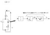
図2は、本発明の一実施例の具体的な構成図である。この実施例は、二次電池でモータ等の負荷を駆動したり、モータの回生で二次電池を充電したりするシステムにおいて、二次電池の充電率を推定演算する機能を設けた例を示す。
図2において、10は二次電池、20はモータ等の負荷、30は二次電池の充電率や満充電容量等を推定する電子制御ユニット(バッテリコントローラ)で、ブログラムを演算するCPUやプログラムや演算結果を記憶するROMやRAMから成るマイクロコンピュータと電子回路等で構成されている。40は電池から充放電される電流を検出する電流センサ、50は電池の端子電圧(単に電圧ともいう)を検出する電圧センサであり、それぞれ電子制御ユニット30に接続されている。上記の電子制御ユニット30は前記図1の前処理フィルタ演算手段3、適応デジタルフィルタ演算手段4、開路電圧演算手段5、充電率演算手段6、満充電容量演算手段7および調整手段8の部分に相当する。また、電流センサ40は電流計測手段1に、電圧センサ50は電圧計測手段2に、それぞれ相当する。FIG. 2 is a specific configuration diagram of an embodiment of the present invention. This embodiment shows an example in which a function for estimating and calculating a charging rate of a secondary battery is provided in a system in which a load such as a motor is driven by a secondary battery or a secondary battery is charged by regeneration of a motor. .
In FIG. 2, 10 is a secondary battery, 20 is a load of a motor, etc., 30 is an electronic control unit (battery controller) that estimates the charging rate, full charge capacity, etc. of the secondary battery. And a microcomputer composed of a ROM and a RAM for storing calculation results and an electronic circuit.
まず、上記の適応デジタルフィルタを用いた開路電圧および充電率の推定方法に関して説明する。
本実施例では、二次電池の電池モデルを下記(数6)式(=数1)のように定義し、(数6)式の電池モデル(連続時間系)を用いて、開路電圧V0を(数7)式(=数2)で近似することで、(数6)式を(数8)式(=数3)とし、(数8)式の両辺にローパスフィルタ処理を施すことによって得られる(数9)式に対して適応デジタルフィルタ演算を行い、A(s)とB(s)の係数パラメータ及び変数dを一括推定し、次いで(数7)式の代わりに(数6)式と等価な下記(数10)式(=数5)に、推定したA(s)とB(s)の係数パラメータを代入してGLPF(s)・V0を算出し、これを開路電圧V0の代用とする。そして公知の開路電圧V0と充電率SOCの関係から充電率を推定するように構成している。First, a method for estimating an open circuit voltage and a charging rate using the adaptive digital filter will be described.
In this embodiment, the battery model of the secondary battery is defined as shown in the following (formula 6) (equation 1), and the open circuit voltage V0 is obtained using the battery model (continuous time system) of the formula (6). Is approximated by Equation (7) (= Equation 2), Equation (6) is changed to Equation (8) (= Equation 3), and low-pass filter processing is performed on both sides of Equation (8). An adaptive digital filter operation is performed on the obtained (Equation 9), and coefficient parameters and variable d of A (s) and B (s) are collectively estimated, and then, instead of (Equation 7), (Equation 6) Substituting the estimated coefficient parameters of A (s) and B (s) into the following equation (equation 10) equivalent to the equation (= Equation 5) to calculate GLPF (s) · V0 , It is a substitute for voltageV 0. The charging rate is estimated from the relationship between the known open circuit voltage V0 and the charging rate SOC.

I:電流 V:電圧 V0:開路電圧
GLPF(s):ローパスフィルタの伝達特性(次数差はn+1以上)
図3は、上記の推定に用いる電池モデルを示す回路図である。図3において、モデルヘの入力は電流I[A](正値:充電、負値:放電)、出力は端子電圧V[V]、開路電圧V0[V](起電力または開放電圧とも言う)であり、R1は電荷移動抵抗、R2は純抵抗、C1は電気二重層容量である。本モデルは正極、負極を特に分離していないリダクションモデル(一次)であるが、実際の電池の充放電特性を比較的正確に示すことが可能である。
この電池モデルは(数11)式で表現できる。なお、sはラプラス演算子である。
I: current V: voltage V0 : open circuit voltage GLPF (s): transfer characteristic of low-pass filter (order difference is n + 1 or more)
FIG. 3 is a circuit diagram showing a battery model used for the above estimation. In FIG. 3, the input to the model is current I [A] (positive value: charge, negative value: discharge), and the output is terminal voltage V [V], open circuit voltage V0 [V] (also referred to as electromotive force or open voltage). R1 is a charge transfer resistance, R2 is a pure resistance, and C1 is an electric double layer capacitance. Although this model is a reduction model (primary) in which the positive electrode and the negative electrode are not particularly separated, it is possible to show the actual charge / discharge characteristics of the battery relatively accurately.
This battery model can be expressed by Equation (11). Note that s is a Laplace operator.
V2=s・GLPF(s)・V
I3=s2・GLPF(s)・I
I2=s・GLPF(s)・I
I1=GLPF(s)・I
上記のように、電池モデルの次数を1次に限定することで、前記(数6)式、(数8)式、(数9)式は、それぞれ(数12)式、(数15)式、(数19)式に対応することになる。
V2 = s · GLPF (s) · V
I3 = s2 · GLPF (s) · I
I2 = s · GLPF (s) · I
I1 = GLPF (s) · I
As described above, by limiting the order of the battery model to the first order, the above (Expression 6), (Expression 8), and (Expression 9) are expressed by (Expression 12) and (Expression 15), respectively. , (Expression 19).
(数19)式は、計測可能な値と未知パラメータの積和式になっているので、一般的な適応デジタルフィルタの標準形(数20)式と一致する。 Since (Equation 19) is a product-sum expression of a measurable value and an unknown parameter, it agrees with a standard form (Equation 20) of a general adaptive digital filter.
y=V2、ωT=[V3,I3,I2,I1]、θT=[−T1,K・T2,K,d]
である。
従って、電流Iと端子電圧Vにフィルタ処理を施した信号を、適応デジタルフィルタ演算に用いることで、未知パラメータベクトルθを推定することが出来る。
y = V2 , ωT = [V3 , I3 , I2 , I1 ], θT = [− T1 , K · T2 , K, d]
It is.
Therefore, the unknown parameter vector θ can be estimated by using a signal obtained by filtering the current I and the terminal voltage V in the adaptive digital filter calculation.
本実施例では、単純な「最小二乗法による適応デジタルフィルタ」の論理的な欠点、すなわち、一度推定値が収束すると、その後パラメータが変化しても再度正確な推定ができない点を改善した「両限トレースゲイン方式」を用いる。
上記(数20)式を前提に未知パラメータベクトルθを推定するための逐次推定アルゴリズムは下記(数21)式に示すようになる。ただし、k時点のパラメータ推定値をθ(k)とする。The present embodiment has improved the logical disadvantage of a simple “adaptive digital filter based on the least squares method”, that is, once the estimated value has converged, accurate estimation cannot be performed again even if the parameter changes thereafter. "Limit trace gain method" is used.
A sequential estimation algorithm for estimating the unknown parameter vector θ based on the above equation (20) is as shown in the following equation (21). However, the parameter estimated value at the time point k is assumed to be θ (k).
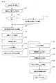
つぎに電子制御ユニット30のマイクロコンピュータが行う処理を図4に示すフローチャートを用いて説明する。なお、同図のルーチンは一定周期T0毎に実施され、I(k)は今回の値、I(k−1)は1回前の値を意味する。Next, processing performed by the microcomputer of the
図4において、ステップS10では、電流I(k)、端子電圧V(k)を計測する。
ステップS20では、二次電池の遮断リレーの判断を行う。バッテリーコントローラ30は二次電池の遮断リレーの制御も行っており、リレー遮断時(電流I=0)はステップS30へ進む。リレー締結時はステップS40へ進む。In FIG. 4, in step S10, current I (k) and terminal voltage V (k) are measured.
In step S20, the secondary battery cutoff relay is determined. The
ステップS30では、端子電圧V(k)を端子電圧初期値V_iniとして記憶する。
ステップS40では、端子電圧の差分値△V(k)を下式に基づき算出する。
△V(k)=V(k)−V_ini
これは、適応デジタルフィルタ内の推定パラメータの初期値を約0としているので、推定演算開始時に推定パラメータが発散しないように、入力を全て0とするためである。リレー遮断時はステップS30を通るので、I=0かつ△V(k)=0なので、推定パラメータは初期状態のままである。In step S30, the terminal voltage V (k) is stored as the terminal voltage initial value V_ini.
In step S40, a terminal voltage difference value ΔV (k) is calculated based on the following equation.
ΔV (k) = V (k) −V_ini
This is because the initial value of the estimation parameter in the adaptive digital filter is set to about 0, so that all the inputs are set to 0 so that the estimation parameter does not diverge when the estimation calculation starts. Since the process goes through step S30 when the relay is cut off, I = 0 and ΔV (k) = 0, so that the estimation parameters remain in the initial state.
ステップS50では、後述する充電率推定値の前回値SOC(k−1)、および満充電容量推定値の前回値Qmax(k−1)から、適応デジタルフィルタ(図1のデジタルフィルタ演算手段4)の調整ゲインλ3を設定する。
実際には、まずSOC(k−1)を入力とし、図5に示すマップに基づき第1調整ゲイン補正係数KSOCλを算出する。図5に示すマップは、充電率−開路電圧特性より予め充電率に対する開路電圧の変化率(△V0/△SOC)を算出し、変化率の大きい領域(△V0/△SOC=大)では補正係数KSOCλが小さく、また変化率の小さい領域(△V0/△SOC=小)では補正係数KSOCλが大きくなるように設定する。
つぎに、Qmax(k−1)を入力とし、図6に示すマップに基づき第2調整ゲイン補正係数KQλを算出する。図6に示すマップは、満充電容量が大きいほど(新品相当時=Qmax_new)補正係数KQλが大きくなるように、満充電容量が小さいほど(古い品相当時=Qmax_old)補正係数KQλが小さくなるように設定する。そして、予め設定した調整ゲイン基準値λ3_BASEと、上記の各補正係数(KSOCλとKQλ)から下記(数22)式に基づき最終調整ゲインλ3を演算する。In step S50, an adaptive digital filter (digital filter calculation means 4 in FIG. 1) is calculated from a previous value SOC (k−1) of a charge rate estimated value, which will be described later, and a previous value Qmax (k−1) of an estimated full charge capacity. ) Of3 ) is set.
Actually, first, SOC (k−1) is input, and the first adjustment gain correction coefficient KSOCλ is calculated based on the map shown in FIG. In the map shown in FIG. 5, the change rate (ΔV0 / ΔSOC) of the open circuit voltage with respect to the charge rate is calculated in advance from the charge rate-open circuit voltage characteristics, and the region where the change rate is large (ΔV0 / ΔSOC = high). Then, the correction coefficient KSOCλ is set to be small, and the correction coefficient KSOCλ is set to be large in a region where the rate of change is small (ΔV0 /ΔSOC = small).
Next, with Qmax (k−1) as an input, a second adjustment gain correction coefficient KQλ is calculated based on the map shown in FIG. Map shown in FIG. 6, the larger the full charge capacity as (new corresponding time= Q max_new) correction factorK q? Increases, as the full charge capacity is smaller (older goods corresponding time= Q max_old) correction factorK q? Is set to be small. Then, the calculation and adjustment gain reference value lambda3 _BASE set in advance, the final adjustment gain lambda3 based on the following equation (22) from the correction coefficient of the(K SOCramuda andK q?).
ステップS60では、ステップS50と同様に、充電率推定値の前回値SOC(k−1)、および満充電容量推定値の前回値Qmax(k−1)から、ローパスフィルタ(図1の前処理フィルタ演算手段3)の時定数pを設定する。実際には、まずSOC(k−1)を入力とし、図7に示すマップに基づき第1時定数補正係数KSOCPを算出する。図7に示すマップは、充電率に対する開路電圧の変化率が大きい領域では補正係数KSOCPが大きく、変化率の小さい領域では補正係数KSOCPが小さくなるように設定する。
つぎに、Qmax(k−1)を入力とし、図8に示すマップに基づき第2時定数補正係数KQPを算出する。図8に示すマップは、満充電容量が大きいほど(新品相当時)補正係数KQPが小さくなるように設定する。そして、予め設定した時定数pBASEと、各補正係数(KSOCPとKQP)から下記(数23)式に基づいて時定数pを演算する。In step S60, as in step S50, the low-pass filter (preprocessing in FIG. 1) is calculated from the previous value SOC (k−1) of the estimated charge rate value and the previous value Qmax (k−1) of the estimated full charge capacity value. The time constant p of the filter calculation means 3) is set. Actually, first, SOC (k−1) is input, and the first time constant correction coefficient KSOCP is calculated based on the map shown in FIG. Map shown in FIG. 7, the correction coefficient KSOCP the change rate is large area of the open circuit voltage is large, a small rate of change areas is set as the correction coefficient KSOCP smaller relative charging rate.
Next, with Qmax (k−1) as an input, a second time constant correction coefficient KQP is calculated based on the map shown in FIG. The map shown in FIG. 8 is set so that the correction coefficient KQP decreases as the full charge capacity increases (when it is equivalent to a newproduct ). Then, the time constant p is calculated from the preset time constant pBASE and each correction coefficient (KSOCP and KQP ) based on the following equation (23).
また、上記の例では、ステップS50とステップS60の両方を用いて調整ゲインλ3と時定数pの両方を調整する場合を例示したが、何れか一方のみを調整してもよい。例えば、ステップS60を削除して調整ゲインλ3のみを補正するか、あるいはステップS50を削除して時定数pのみを補正するようにしてもよい。Further, in the above example has illustrated the case of adjusting both the constant p when the adjustment gain lambda3 using both step S50 and step S60, may be adjusted either one. For example, correcting only adjustment gain lambda3 to delete the step S60, or may be corrected only time constant p remove the step S50.
次に、ステップS70では、電流I(k)と端子電圧差分値△V(k)に、ステップS60で設定した時定数pを用いて下記(数24)式に基づきローパスフィルタ、バンドパスフィルタの処理を施し、I1〜I3およびV1〜V3を算出する。Next, in step S70, the current I (k) and the terminal voltage difference value ΔV (k) are used for the low-pass filter and the band-pass filter based on the following equation (Equation 24) using the time constant p set in step S60. Processing is performed to calculate I1 to I3 and V1 to V3 .
ステップS80では、ステップS70で算出したI1〜I3、V2〜V3、およびステップS50で算出した調整ゲインλ3を前記(数21)式に代入し、パラメータ推定値θ(k)を算出する。
ただし、
y=V2、ωT[V3,I3,I2,I1]、θT=[−T1,K・T2,K,d]
である。
In step S80, I1 to I3 and V2 to V3 calculated in step S70 and the adjustment gain λ3 calculated in step S50 are substituted into the equation (21), and the parameter estimated value θ (k) is calculated. calculate.
However,
y = V2 , ωT [V3 , I3 , I2 , I1 ], θT = [− T1 , K · T2 , K, d]
It is.
ステップS90では、ステップS80で算出したパラメータ推定値θ(k)の中からT1、K・T2、Kと、(数24)式で算出したI1〜I2およびV1〜V2を下記(数25)式に代入し、開路電圧△V0を演算する。In step S90, T1 , K · T2 , K, and I1 to I2 and V1 to V2 calculated by the equation (24) are calculated from the parameter estimated values θ (k) calculated in step S80. Substituting into the following (Equation 25), the open circuit voltage ΔV0 is calculated.
ただし、ここで求まるのは推定演算開始時からの開路電圧推定値の変化分△V0(k)であるため、後段のステップS100で初期値を加算する。
However, since what is obtained here is the change ΔV0 (k) of the open circuit voltage estimated value from the start of the estimation calculation, the initial value is added in step S100 in the subsequent stage.
ステップS100では、ステップS90で算出した△V0(k)に開路電圧初期値すなわち端子電圧初期値V_iniを加算して、開路電圧推定値V0(k)を下式で算出する。
V0(k)=△V0(k)+V_ini
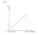
ステップS110では、図9に示す開路電圧と充電率の相関マップを用いて、ステップS100で算出したV0(k)から充電率SOC(k)を算出する。なお、図9のVLはSOC=0%に、VHはSOC=100%に相当する開路電圧である。In step S100, the open circuit voltage initial value, that is, the terminal voltage initial value V_ini, is added to ΔV0 (k) calculated in step S90, and the open circuit voltage estimated value V0 (k) is calculated by the following equation.
V0 (k) = ΔV0 (k) + V_ini
In step S110, the charge rate SOC (k) is calculated from V0 (k) calculated in step S100, using the correlation map between the open circuit voltage and the charge rate shown in FIG. In FIG. 9,VL is an open circuit voltage corresponding to SOC = 0%, andVH is an open circuit voltage corresponding to SOC = 100%.
ステップS120では、ステップS110で算出した充電率SOC(k)と電流I(k)から満充電容量Qmax(k)を演算する。その方法としては、例えば、下記(数26)式に示すように、電流I(k)を充電率推定値の微分値で除算して求めることが出来る。In step S120, the full charge capacity Qmax (k) is calculated from the charging rate SOC (k) and current I (k) calculated in step S110. As the method, for example, as shown in the following (Equation 26), the current I (k) can be obtained by dividing by the differential value of the estimated charge rate.
上記のようにして求めた充電率SOC(k)と満充電容量Qmax(k)の値は、次回の演算においてステップS50、S60の補正係数演算に用いられる。
The values of the charging rate SOC (k) and the full charge capacity Qmax (k) obtained as described above are used for the correction coefficient calculation in steps S50 and S60 in the next calculation.
なお、ステップS50、S60で用いる補正特性(図5〜図8)においては、△V0/△SOCや満充電容量に基づいて、調整ゲインや時定数を連続的に変更する場合を示しているが、段階的(ステップ的)に変更しても良い。In the correction characteristics (FIGS. 5 to 8) used in steps S50 and S60, the adjustment gain and the time constant are continuously changed based on ΔV0 / ΔSOC and the full charge capacity. However, it may be changed step by step.
次に、本発明の効果をシミュレーションにより説明する。
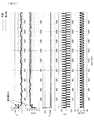
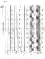
図10〜図13は、本発明の効果を説明するためのシミュレーション結果の一例を示す図であり、電流を定期的に(ステップ状に)±18A変化させ、端子電圧計測値に最大±0.01Vの白色ノイズを印加した状態において、時間t1に電池パラメータが0℃→25℃に変化した際の結果を示す。Next, the effect of the present invention will be described by simulation.
10 to 13 are diagrams showing an example of a simulation result for explaining the effect of the present invention, in which the current is changed periodically (stepwise) by ± 18 A, and the terminal voltage measurement value is ± 0. The result when the battery parameter changes from 0 ° C. to 25 ° C. at time t1 in a state where white noise of 01 V is applied is shown.
図10は、従来例1(λ3=0.01固定)で、充電率初期値=90%の場合、図11は従来例2(λ3=0.1固定)、充電率初期値=20%の場合である。FIG. 10 shows Conventional Example 1 (λ3 = 0.01 fixed) and the initial charging rate is 90%. FIG. 11 shows Conventional Example 2 (λ3 = 0.1 fixed) and Charging Rate Initial Value = 20. %.
図12、図13は本発明において、調整ゲイン基本値λ3_BASE=0.1とし、補正係数KSOCλをSOC=90%でKSOCλ=1.0、SOC=20%でKSOCλ=0.1とした結果であり、図12は充電率初期値=90%、図13は充電率初期値=20%の場合を示す。12 and 13, in the present invention, the adjustment gain basic value λ3 —BASE = 0.1, the correction coefficient K SOCλ is SOC = 90%, K SOCλ = 1.0, SOC = 20% and K SOCλ = 0.1. FIG. 12 shows the case where the charging rate initial value = 90%, and FIG. 13 shows the case where the charging rate initial value = 20%.
従来の充電率推定装置(例えば前記特許文献1)においては、電池の劣化による満充電容量の変化や現在の充電率によって電流に対する端子電圧の振幅が変化するにもかかわらず、適応デジタルフィルタの調整ゲイン(推定演算の応答速度を調整する定数)やローパスフィルタの時定数が一定であった。したがって、たとえば図9に示したような充電率−開路電圧特性を有する電池において、比較的低い充電率(SOC1)すなわち充電率の変化に対して開路電圧の変化が大きいときに最適になるようにゲインおよび時定数を調整してしまうと、充電率の高い(SOC2)すなわち充電率の変化に対して開路電圧の変化が小さい場合には、調整ゲインが小さすぎると共に時定数が大きすぎるため、パラメータ推定の遅れが大きくなってしまうという問題が生じる。また、比較的高い充電率(SOC2)すなわち充電率の変化に対して開路電圧の変化が小さいときに最適になるようにゲインおよび時定数を調整してしまうと、充電率の低い(SOC1)場合には調整ゲインが大きすぎると共に時定数が小さすぎるため、ノイズの影響により推定誤差が生じてしまう。 In the conventional charging rate estimation device (for example, Patent Document 1), the adjustment of the adaptive digital filter is performed despite the change of the full charge capacity due to the deterioration of the battery and the amplitude of the terminal voltage with respect to the current depending on the current charging rate. The gain (a constant for adjusting the response speed of the estimation calculation) and the time constant of the low-pass filter were constant. Therefore, for example, in a battery having a charging rate-open circuit voltage characteristic as shown in FIG. 9, it is optimal when the change in the open circuit voltage is large with respect to a relatively low charging rate (SOC1), that is, a change in the charging rate. If the gain and time constant are adjusted, if the charge rate is high (SOC2), that is, if the change in the open circuit voltage is small relative to the change in the charge rate, the adjustment gain is too small and the time constant is too large. There arises a problem that the estimation delay becomes large. Also, if the gain and time constant are adjusted so as to be optimal when the change in the open circuit voltage is small relative to the change in the charge rate, that is, the charge rate is low (SOC1) Since the adjustment gain is too large and the time constant is too small, an estimation error occurs due to the influence of noise.
したがって従来例においては、図10に示すように、調整ゲインを比較的低めに(λ3=0.01)に設定した場合には、充電率の高い(90%)すなわち開路電圧の変化に対する充電率の変化が緩やかな領域においては、電流に対する端子電圧Vの振幅が小さいため、各パラメータ推定値が真値へと到達する速度が遅くなってしまっている。また、図11に示すように調整ゲインを比較的高めに(λ3=0.1)に設定した場合には、充電率の低い(20%)すなわち開路電圧の変化に対する充電率の変化が急峻な領域においては、端子電圧に印加したノイズの影響により、パラメータ推定誤差(変動)が生じている。Therefore, in the conventional example, as shown in FIG. 10, when the adjustment gain is set relatively low (λ3 = 0.01), the charging rate is high (90%), that is, the charging with respect to the change in the open circuit voltage. In a region where the rate change is slow, the amplitude of the terminal voltage V with respect to the current is small, so that the speed at which each parameter estimated value reaches the true value is slow. Further, as shown in FIG. 11, when the adjustment gain is set to be relatively high (λ3 = 0.1), the charging rate is low (20%), that is, the change in the charging rate with respect to the change in the open circuit voltage is steep. In such a region, parameter estimation error (variation) occurs due to the effect of noise applied to the terminal voltage.
一方、本発明においては、図12に示すように図10と同条件においても調整ゲインが高め(λ3=0.1)に調整されるため、パラメータは速やかに真値へと到達している。また、図13に示すように図11と同条件においても調整ゲインが低め(λ3=0.01)に調整されるため、ノイズによる影響小さくすることができる。
このように、現在の充電率に基づいて調整ゲインを補正することにより、充電率によらず大きな遅れを生じることがなく、かつノイズによる推定誤差を生じることもなく、電池パラメータを精度よく推定することができる。なお、以上は充電率による効果を説明したが、満充電容量に関しても同様の効果を得ることが可能である。On the other hand, in the present invention, as shown in FIG. 12, since the adjustment gain is adjusted to be high (λ3 = 0.1) even under the same conditions as in FIG. 10, the parameter quickly reaches the true value. . Also, as shown in FIG. 13, even under the same conditions as in FIG. 11, the adjustment gain is adjusted to be lower (λ3 = 0.01), so that the influence of noise can be reduced.
In this way, by correcting the adjustment gain based on the current charging rate, the battery parameter is accurately estimated without causing a large delay regardless of the charging rate and without causing an estimation error due to noise. be able to. In addition, although the effect by a charging rate was demonstrated above, the same effect can be acquired also regarding full charge capacity.
以上、説明したように、本発明においては、充電率変化量△SOCに対して開路電圧変化量△V0が小さい場合には、調整ゲインを大きくするか、ローパスフィルタの時定数を小さくするかの少なくとも一方を行うことにより、パラメータ推定速度が速くなるため、電圧が微小振幅であっても精度よく充電率を推定演算することができる。また、充電率変化量△SOCに対して開路電圧変化量△V0が大きい場合には、調整ゲインを小さくするか、ローパスフィルタ時定数を大きくするかの少なくとも一方を行うことにより、信号に生じるノイズによる影響を受けることなく電池パラメータを推定できる。そのため、充電率を正確に推定演算することができる。As described above, in the present invention, when the open circuit voltage change amount ΔV0 is small with respect to the charge rate change amount ΔSOC, whether the adjustment gain is increased or the time constant of the low-pass filter is decreased. By performing at least one of the above, the parameter estimation speed is increased, so that the charging rate can be estimated and calculated accurately even if the voltage has a small amplitude. Further, when the open circuit voltage change amount ΔV0 is larger than the charge rate change amount ΔSOC, it is generated in the signal by performing at least one of decreasing the adjustment gain or increasing the low-pass filter time constant. Battery parameters can be estimated without being affected by noise. Therefore, it is possible to accurately estimate and calculate the charging rate.
また、満充電容量が大きい場合には、電流に対する開路電圧の変化量は小さくなるため、端子電圧の変化量(振幅)も小さくなる。この場合には、調整ゲインを大きくするか、ローパスフィルタ時定数を小さくするかの少なくとも一方を行うことにより、パラメータ推定速度が速くなるため、電圧が微小振幅であっても精度よく充電率を推定演算することができる。また、電池の劣化のため新品時に比較して満充電容量が小さくなった場合には、電流に対する開路電圧の変化量は大きくなるため、端子電圧の振幅も大きくなる。この場合には調整ゲインを小さくするか、ローパスフィルタ時定数を大きくするかの少なくとも一方を行うことにより、信号に生じるノイズによる影響を受けることなく電池パラメータを推定できるため、充電率を正確に推定演算することができる。 Further, when the full charge capacity is large, the amount of change in the open circuit voltage with respect to the current is small, so the amount of change (amplitude) of the terminal voltage is also small. In this case, increasing the adjustment gain or reducing the low-pass filter time constant will increase the parameter estimation speed, so the charge rate can be estimated accurately even if the voltage is very small. It can be calculated. In addition, when the full charge capacity becomes smaller than that of a new battery due to deterioration of the battery, the amount of change in the open circuit voltage with respect to the current increases, and the amplitude of the terminal voltage also increases. In this case, the battery parameter can be estimated without being affected by noise generated in the signal by reducing the adjustment gain or increasing the low-pass filter time constant, so the charging rate can be estimated accurately. It can be calculated.
1…電流計測手段 2…電圧計測手段
3…前処理フィルタ演算手段 4…適応デジタルフィルタ演算手段
5…開路電圧演算手段 6…充電率演算手段
7…満充電容量演算手段 8…調整手段
10…二次電池 20…負荷
30…電子制御ユニット 40…電流センサ
50…電圧センサDESCRIPTION OF
Claims (4)
Translated fromJapanese二次電池の端子電圧Vを検出する端子電圧検出手段と、
二次電池の電池モデルを下記(数1)式のように定義し、(数1)式の電池モデルを用いて、開路電圧V0を下記(数2)式で近似することで、(数1)式を(数3)式とし、(数3)式の両辺にローパスフィルタ処理を施すことによって得られる(数4)式に対して適応デジタルフィルタ演算を行い、A(s)とB(s)の係数パラメータ及び変数dを一括推定するパラメータ推定演算手段と、
前記電流Iおよび端子電圧Vの検出値と前記パラメータの推定値とを(数1)式と等価な下記(数5)式に代入して開路電圧V0を演算する開路電圧演算手段と、
前記開路電圧V0から充電率SOCを演算する充電率演算手段と、を有する二次電池の充電率推定装置において、
前記適応デジタルフィルタにおけるパラメータ推定演算の応答速度と前記ローパスフィルタの時定数とに対して、前記推定した充電率に基づいて求めた充電率に対する開路電圧の変化率(△V0/△SOC)が大きい領域では、パラメータ推定演算の応答速度を小さく調整する応答速度の調整と、ローパスフィルタの時定数を大きな値に調整する時定数の調整との少なくとも一方を行い、充電率に対する開路電圧の変化率(△V0/△SOC)が小さい領域では、パラメータ推定演算の応答速度を大きく調整する応答速度の調整と、ローパスフィルタの時定数を小さな値に調整する時定数の調整との少なくとも一方を行う適応デジタルフィルタ定数調整手段を有することを特徴とする二次電池の充電率推定装置。
I:電流 V:電圧 V0:開路電圧
GLPF(s):ローパスフィルタの伝達特性(次数差はn+1以上)Current detecting means for detecting the current I of the secondary battery;
A terminal voltage detecting means for detecting a terminal voltage V of the secondary battery;
By defining the battery model of the secondary battery as in the following (Equation 1), and approximating the open circuit voltage V0 by the following (Equation 2) using the battery model of (Equation 1), Formula (1) is changed to Formula (3), and adaptive digital filter operation is performed on Formula (4) obtained by performing low-pass filter processing on both sides of Formula (3), and A (s) and B ( parameter estimation calculation means for collectively estimating the coefficient parameter and variable d of s);
An open circuit voltage computing means for computing the open circuit voltage V0 by substituting the detected values of the current I and the terminal voltage V and the estimated values of the parameters into the following (Equation 5) equivalent to the (Equation 1):
In charging rate estimating device for a secondary battery with a charging rate calculating means for calculating a charging rate SOC from the open-circuit voltage V0,
With respect to the response speed of the parameter estimation calculation in the adaptive digital filter and the time constant of the low-pass filter, the change rate (ΔV0 / ΔSOC) of the open circuit voltage with respect to the charging rate obtained based on the estimated charging rate is In a large area, at least one of adjustment of the response speed for adjusting the response speed of the parameter estimation calculation to be small and adjustment of the time constant for adjusting the time constant of the low-pass filter to a large value is performed, and the rate of change of the open circuit voltage with respect to the charging rate In a region where (ΔV0 / ΔSOC) is small, at least one of adjustment of the response speed for largely adjusting the response speed of the parameter estimation calculation and adjustment of the time constant for adjusting the time constant of the low-pass filter to a small value is performed. An apparatus for estimating a charging rate of a secondary battery, comprising adaptive digital filter constant adjusting means.
I: current V: voltage V0 : open circuit voltage GLPF (s): transfer characteristic of low-pass filter (order difference is n + 1 or more)
前記適応デジタルフィルタ定数調整手段は、前記満充電容量が大きいほどパラメータ推定演算の応答速度を大きくする調整とローパスフィルタの時定数を小さくする調整との少なくとも一方を行い、前記満充電容量が小さいほどパラメータ推定演算の応答速度を小さくする調整と、ローパスフィルタの時定数を大きくする調整との少なくとも一方を行うことを特徴とする請求項1に記載の二次電池の充電率推定装置。A full charge capacity calculating means for calculating the full charge capacity of the secondary battery based on the current I obtained by the current detecting means and the charge rate obtained by the charge rate calculating means;
The adaptive digital filter constant adjusting means performs at least one of an adjustment for increasing a response speed of the parameter estimation calculation as the full charge capacity increases and an adjustment for reducing a time constant of the low-pass filter, and as the full charge capacity decreases. 2. The secondary battery charge rate estimation apparatus according to claim 1, wherein at least one of adjustment for decreasing a response speed of the parameter estimation calculation and adjustment for increasing a time constant of the low-pass filter is performed.
Priority Applications (1)
| Application Number | Priority Date | Filing Date | Title |
|---|---|---|---|
| JP2005106166AJP2006284431A (en) | 2005-04-01 | 2005-04-01 | Secondary battery charge rate estimation device |
Applications Claiming Priority (1)
| Application Number | Priority Date | Filing Date | Title |
|---|---|---|---|
| JP2005106166AJP2006284431A (en) | 2005-04-01 | 2005-04-01 | Secondary battery charge rate estimation device |
Publications (1)
| Publication Number | Publication Date |
|---|---|
| JP2006284431Atrue JP2006284431A (en) | 2006-10-19 |
Family
ID=37406507
Family Applications (1)
| Application Number | Title | Priority Date | Filing Date |
|---|---|---|---|
| JP2005106166AWithdrawnJP2006284431A (en) | 2005-04-01 | 2005-04-01 | Secondary battery charge rate estimation device |
Country Status (1)
| Country | Link |
|---|---|
| JP (1) | JP2006284431A (en) |
Cited By (17)
| Publication number | Priority date | Publication date | Assignee | Title |
|---|---|---|---|---|
| EP2618168A4 (en)* | 2010-09-16 | 2015-08-26 | Calsonic Kansei Corp | DEVICE FOR ESTIMATING PARAMETERS BY MEANS OF A FILTER |
| US20150340885A1 (en)* | 2014-05-20 | 2015-11-26 | Samsung Sdi Co., Ltd. | Battery charging method and battery management system therefor |
| US9272635B2 (en) | 2012-11-16 | 2016-03-01 | Toyota Jidosha Kabushiki Kaisha | Power storage system and method of calculating full charge capacity |
| JP2016537645A (en)* | 2013-09-18 | 2016-12-01 | ルノー エス.ア.エス. | Method for estimating degradation of storage battery cells over time |
| CN106707181A (en)* | 2016-12-05 | 2017-05-24 | 澳特卡新能源科技(上海)有限公司 | Cell parameter and charged state estimation method of lithium ion |
| WO2018029849A1 (en)* | 2016-08-12 | 2018-02-15 | 富士通株式会社 | Estimation device, estimation program, and charging control device |
| US10151802B2 (en) | 2016-11-01 | 2018-12-11 | Duracell U.S. Operations, Inc. | Reusable battery indicator with electrical lock and key |
| US10184988B2 (en) | 2012-12-27 | 2019-01-22 | Duracell U.S. Operations, Inc. | Remote sensing of remaining battery capacity using on-battery circuitry |
| US10297875B2 (en) | 2015-09-01 | 2019-05-21 | Duracell U.S. Operations, Inc. | Battery including an on-cell indicator |
| US10416309B2 (en) | 2013-06-21 | 2019-09-17 | Duracell U.S. Operations, Inc. | Systems and methods for remotely determining a battery characteristic |
| US10483634B2 (en) | 2016-11-01 | 2019-11-19 | Duracell U.S. Operations, Inc. | Positive battery terminal antenna ground plane |
| US10608293B2 (en) | 2016-11-01 | 2020-03-31 | Duracell U.S. Operations, Inc. | Dual sided reusable battery indicator |
| US10818979B2 (en) | 2016-11-01 | 2020-10-27 | Duracell U.S. Operations, Inc. | Single sided reusable battery indicator |
| US10916850B2 (en) | 2013-05-23 | 2021-02-09 | Duracell U.S. Operations, Inc. | Omni-directional antenna for a cylindrical body |
| US10964980B2 (en) | 2014-05-30 | 2021-03-30 | Duracell U.S. Operations, Inc. | Indicator circuit decoupled from a ground plane |
| US11024891B2 (en) | 2016-11-01 | 2021-06-01 | Duracell U.S. Operations, Inc. | Reusable battery indicator with lock and key mechanism |
| US11837754B2 (en) | 2020-12-30 | 2023-12-05 | Duracell U.S. Operations, Inc. | Magnetic battery cell connection mechanism |
- 2005
- 2005-04-01JPJP2005106166Apatent/JP2006284431A/ennot_activeWithdrawn
Cited By (28)
| Publication number | Priority date | Publication date | Assignee | Title |
|---|---|---|---|---|
| US9784794B2 (en) | 2010-09-16 | 2017-10-10 | Calsonic Kansei Corporation | Parameter estimation device using filter |
| EP2618168A4 (en)* | 2010-09-16 | 2015-08-26 | Calsonic Kansei Corp | DEVICE FOR ESTIMATING PARAMETERS BY MEANS OF A FILTER |
| US9272635B2 (en) | 2012-11-16 | 2016-03-01 | Toyota Jidosha Kabushiki Kaisha | Power storage system and method of calculating full charge capacity |
| US10184988B2 (en) | 2012-12-27 | 2019-01-22 | Duracell U.S. Operations, Inc. | Remote sensing of remaining battery capacity using on-battery circuitry |
| US10698032B2 (en) | 2012-12-27 | 2020-06-30 | Duracell U.S. Operations, Inc. | Remote sensing of remaining battery capacity using on-battery circuitry |
| US10916850B2 (en) | 2013-05-23 | 2021-02-09 | Duracell U.S. Operations, Inc. | Omni-directional antenna for a cylindrical body |
| US11740291B2 (en) | 2013-06-21 | 2023-08-29 | Duracell U.S. Operations, Inc. | Systems and methods for remotely determining a battery characteristic |
| US11307259B2 (en) | 2013-06-21 | 2022-04-19 | Duracell U.S. Operations, Inc. | Systems and methods for remotely determining a battery characteristic |
| US10859705B2 (en) | 2013-06-21 | 2020-12-08 | Duracell U.S. Operations, Inc. | Systems and methods for remotely determining a battery characteristic |
| US10416309B2 (en) | 2013-06-21 | 2019-09-17 | Duracell U.S. Operations, Inc. | Systems and methods for remotely determining a battery characteristic |
| JP2016537645A (en)* | 2013-09-18 | 2016-12-01 | ルノー エス.ア.エス. | Method for estimating degradation of storage battery cells over time |
| US9634497B2 (en)* | 2014-05-20 | 2017-04-25 | Samsung Sdi Co., Ltd. | Battery charging method and battery management system therefor |
| US20150340885A1 (en)* | 2014-05-20 | 2015-11-26 | Samsung Sdi Co., Ltd. | Battery charging method and battery management system therefor |
| US10964980B2 (en) | 2014-05-30 | 2021-03-30 | Duracell U.S. Operations, Inc. | Indicator circuit decoupled from a ground plane |
| US10297875B2 (en) | 2015-09-01 | 2019-05-21 | Duracell U.S. Operations, Inc. | Battery including an on-cell indicator |
| WO2018029849A1 (en)* | 2016-08-12 | 2018-02-15 | 富士通株式会社 | Estimation device, estimation program, and charging control device |
| US10818979B2 (en) | 2016-11-01 | 2020-10-27 | Duracell U.S. Operations, Inc. | Single sided reusable battery indicator |
| US10608293B2 (en) | 2016-11-01 | 2020-03-31 | Duracell U.S. Operations, Inc. | Dual sided reusable battery indicator |
| US10483634B2 (en) | 2016-11-01 | 2019-11-19 | Duracell U.S. Operations, Inc. | Positive battery terminal antenna ground plane |
| US10971769B2 (en) | 2016-11-01 | 2021-04-06 | Duracell U.S. Operations, Inc. | Reusable battery indicator with electrical lock and key |
| US11024892B2 (en) | 2016-11-01 | 2021-06-01 | Duracell U.S. Operations, Inc. | Dual sided reusable battery indicator |
| US11024891B2 (en) | 2016-11-01 | 2021-06-01 | Duracell U.S. Operations, Inc. | Reusable battery indicator with lock and key mechanism |
| US11031686B2 (en) | 2016-11-01 | 2021-06-08 | Duracell U.S. Operations, Inc. | Positive battery terminal antenna ground plane |
| US10151802B2 (en) | 2016-11-01 | 2018-12-11 | Duracell U.S. Operations, Inc. | Reusable battery indicator with electrical lock and key |
| US11664539B2 (en) | 2016-11-01 | 2023-05-30 | Duracell U.S. Operations, Inc. | Dual sided reusable battery indicator |
| US11696942B2 (en) | 2016-11-01 | 2023-07-11 | Duracell U.S. Operations, Inc. | Reusable battery indicator with electrical lock and key |
| CN106707181A (en)* | 2016-12-05 | 2017-05-24 | 澳特卡新能源科技(上海)有限公司 | Cell parameter and charged state estimation method of lithium ion |
| US11837754B2 (en) | 2020-12-30 | 2023-12-05 | Duracell U.S. Operations, Inc. | Magnetic battery cell connection mechanism |
Similar Documents
| Publication | Publication Date | Title |
|---|---|---|
| JP4830382B2 (en) | Secondary battery charge rate estimation device | |
| JP2006284431A (en) | Secondary battery charge rate estimation device | |
| JP4547908B2 (en) | Secondary battery input / output possible power estimation device | |
| JP3714321B2 (en) | Secondary battery charge rate estimation device | |
| JP3714333B2 (en) | Secondary battery input / output possible power estimation device | |
| JP4692246B2 (en) | Secondary battery input / output possible power estimation device | |
| JP5842421B2 (en) | Battery state estimation device | |
| US10473723B2 (en) | Parameter and state limiting in model based battery control | |
| JP6614176B2 (en) | Battery state estimation device | |
| JP2012057998A (en) | Charge rate calculation apparatus for secondary battery and charge rate calculation method | |
| JP5163542B2 (en) | Secondary battery input / output possible power estimation device | |
| JP4910300B2 (en) | Secondary battery full charge capacity estimation device | |
| JP2008164417A (en) | Secondary battery internal resistance estimation device | |
| JP3714246B2 (en) | Secondary battery charge rate estimation device | |
| JP3714314B2 (en) | Secondary battery charge rate estimation device | |
| JP4788307B2 (en) | Secondary battery input / output possible power estimation device | |
| JP2010203935A (en) | Device of estimating inputtable/outputtable power of secondary battery | |
| JP3852372B2 (en) | Secondary battery charge rate estimation device | |
| JP4923462B2 (en) | Secondary battery charge rate estimation device | |
| JP3714330B2 (en) | Secondary battery charge rate estimation device | |
| JP4103569B2 (en) | Secondary battery charge rate estimation device | |
| JP4720364B2 (en) | Secondary battery internal resistance estimation device | |
| JP3852371B2 (en) | Secondary battery charge rate estimation device | |
| JP4666149B2 (en) | Secondary battery input / output possible power estimation device | |
| JP3714284B2 (en) | Secondary battery charge rate estimation device |
Legal Events
| Date | Code | Title | Description |
|---|---|---|---|
| A621 | Written request for application examination | Free format text:JAPANESE INTERMEDIATE CODE: A621 Effective date:20080227 | |
| A761 | Written withdrawal of application | Free format text:JAPANESE INTERMEDIATE CODE: A761 Effective date:20090831 |