JP2006277727A - Layout processing method, information processing apparatus, and computer program - Google Patents
Layout processing method, information processing apparatus, and computer programDownload PDFInfo
- Publication number
- JP2006277727A JP2006277727AJP2006048014AJP2006048014AJP2006277727AJP 2006277727 AJP2006277727 AJP 2006277727AJP 2006048014 AJP2006048014 AJP 2006048014AJP 2006048014 AJP2006048014 AJP 2006048014AJP 2006277727 AJP2006277727 AJP 2006277727A
- Authority
- JP
- Japan
- Prior art keywords
- layout
- container
- data area
- size
- content
- Prior art date
- Legal status (The legal status is an assumption and is not a legal conclusion. Google has not performed a legal analysis and makes no representation as to the accuracy of the status listed.)
- Withdrawn
Links
Images


Classifications
- G—PHYSICS
- G06—COMPUTING OR CALCULATING; COUNTING
- G06T—IMAGE DATA PROCESSING OR GENERATION, IN GENERAL
- G06T11/00—2D [Two Dimensional] image generation
- G06T11/60—Editing figures and text; Combining figures or text
- G—PHYSICS
- G06—COMPUTING OR CALCULATING; COUNTING
- G06F—ELECTRIC DIGITAL DATA PROCESSING
- G06F40/00—Handling natural language data
- G06F40/10—Text processing
- G06F40/103—Formatting, i.e. changing of presentation of documents
Landscapes
- Engineering & Computer Science (AREA)
- Theoretical Computer Science (AREA)
- Physics & Mathematics (AREA)
- General Physics & Mathematics (AREA)
- Audiology, Speech & Language Pathology (AREA)
- Artificial Intelligence (AREA)
- Health & Medical Sciences (AREA)
- Computational Linguistics (AREA)
- General Health & Medical Sciences (AREA)
- General Engineering & Computer Science (AREA)
- Processing Or Creating Images (AREA)
- Editing Of Facsimile Originals (AREA)
- Document Processing Apparatus (AREA)
- User Interface Of Digital Computer (AREA)
Abstract
Translated fromJapaneseDescription
Translated fromJapanese本発明は、テキストやイメージで構成されたドキュメントの生成、編集、そして印刷のための技術に関するものであり、更に詳しくは、バリアブルデータドキュメントの生成、編集、そして印刷に好適なものである。 The present invention relates to a technique for generating, editing, and printing a document composed of text and images, and more particularly, suitable for generating, editing, and printing a variable data document.
近年、商品の多品種化で商品ライフが短くなっていること、インターネット利用の普及による消費者のカスタマイズサービス指向などの要因からCRM(Customer Relationship Management)、One-to-Oneマーケティングの必要性が注目されている。これらの手法は、顧客満足度を高め、顧客の開拓や囲い込みを目指すという目的に対して非常に効果的なものである。 In recent years, the need for CRM (Customer Relationship Management) and One-to-One marketing has attracted attention due to factors such as the shortening of product life due to the increase in product variety and the orientation of consumer customization services due to the widespread use of the Internet. Has been. These methods are very effective for the purpose of increasing customer satisfaction and aiming to develop and lock in customers.
One-to-Oneマーケティングはデータベース・マーケティングの一種で、顧客の年齢、性別、趣味、嗜好、購買履歴等の個人属性情報をデータベース化し、その内容を分析、顧客のニーズに合った提案を行うものである。One-to-Oneマーケティングの代表的な具体的手法としてバリアブルプリントが挙げられる。特に、最近ではDTP(デスクトップパブリッシング)技術の進展とデジタル印刷装置の普及に伴って、文書を顧客毎にカスタマイズして出力するバリアブルプリントシステムが開発されている。このようなバリアブルプリントシステムでは、顧客毎に異なる量のコンテンツが最適にレイアウトされたカスタマイズ文書を作成することが求められる。 One-to-One marketing is a type of database marketing that creates a database of personal attribute information such as customer age, gender, hobbies, preferences, purchase history, etc., analyzes the content, and makes proposals that meet customer needs It is. Variable print is a typical example of one-to-one marketing. In particular, recently, with the advancement of DTP (desktop publishing) technology and the spread of digital printing apparatuses, variable print systems that customize and output documents for each customer have been developed. In such a variable print system, it is required to create a customized document in which different amounts of content are optimally laid out for each customer.
一般に、バリアブルプリントシステムにおいてそのようなカスタマイズ文書を作成する際には、ドキュメント上にコンテナをレイアウトする。コンテナとはコンテンツ(描画内容)を描画するための部分領域(データ領域)であり、フィールド領域と呼ばれることもある。すなわち、ドキュメント上にこのようなコンテナをレイアウトし、データベースとレイアウトを関連付ける(データベースの各コンテンツと各コンテナとを関連付ける)といった作業により、カスタマイズ文書(ドキュメント)を作成する。本明細書ではこのようなドキュメントをバリアブルデータドキュメントという。 Generally, when creating such a customized document in the variable print system, a container is laid out on the document. A container is a partial area (data area) for drawing content (drawing contents) and is sometimes called a field area. That is, a customized document (document) is created by laying out such a container on a document and associating the database with the layout (associating each content of the database with each container). In this specification, such a document is referred to as a variable data document.
このようなバリアブルプリントシステムにおいて、レイアウトされた各コンテナには顧客によって異なるコンテンツを流し込むことが可能である。従って、コンテンツに流し込まれるデータのサイズは可変であり、これに対してコンテナのサイズが固定であると次のような課題が生じる。例えば、コンテナのサイズよりも大きなサイズのテキストデータが流し込まれた場合には全てのテキストをそのコンテナ内に表示出来なくなってしまう。あるいは、コンテナのサイズよりも大きなサイズのイメージデータが流し込まれた場合には、そのイメージの一部が欠落してしまう。このような問題をオーバーフローと呼ぶ。 In such a variable print system, different contents can be poured into each laid-out container depending on the customer. Therefore, the size of data to be flowed into the content is variable. On the other hand, if the size of the container is fixed, the following problem occurs. For example, when text data having a size larger than the size of the container is inserted, all text cannot be displayed in the container. Alternatively, when image data having a size larger than the size of the container is inserted, a part of the image is lost. Such a problem is called overflow.
なお、コンテンツがイメージデータの場合には、当該イメージを縮小してコンテナ内に描画することも考えられるが、イメージが極端に小さくなってしまうといった弊害が生じる可能性がある。また、固定サイズのコンテナ内に入りきらないテキストデータが挿入された場合に、テキストのフォントサイズを縮小し、当該コンテナ内に全てのテキストを表示可能にする技術も提案されている。しかしながら、このようにフォントサイズを調節する場合、フォントサイズが小さくなりすぎて、ドキュメント全体のバランスが崩れたり、読みにくくなるという課題が生じる。 If the content is image data, it may be possible to reduce the image and draw it in the container. However, there is a possibility that the image may become extremely small. In addition, a technique has been proposed in which, when text data that does not fit in a fixed-size container is inserted, the font size of the text is reduced and all text can be displayed in the container. However, when the font size is adjusted in this way, the font size becomes too small, resulting in a problem that the balance of the entire document is lost or difficult to read.
このような課題を解決するための自動レイアウトの技術として、ある文字領域のサイズが大きくなった場合に、隣接した領域との間隔を保つべく当該隣接する領域のサイズを小さくする技術が特許文献1の「レイアウトデザイン装置」に開示されている。
特許文献1に記載の技術には、テキストの入力に応じて文字領域が拡大されていくことが記載されている。しかしながら、文字領域のサイズが大きくなった場合、隣接した領域は間隔を保つべく縮小されてしまうため、入力されるテキスト量が増加するに従い、隣接した領域は縮小され続けてしまうといった問題点があった。 The technique described in
更に、特許文献1では、上述したようなデータベースと各レイアウト枠を関連付けてコンテンツデータを流し込むことで、顧客毎にカスタマイズした文書を作成するバリアブルプリントシステムについては考慮されていなかった。 Further,
また、バリアブルデータプリントを考慮したレイアウト方法として、固定のコンテナを作成し、そこにコンテンツデータを流し込んでいくものがある。しかし、固定サイズのコンテナを用いる場合、コンテナサイズより大きいサイズのコンテンツデータが流し込まれると、オーバーフローが生じるという問題が生じてしまう。また、そのような場合に、フォントサイズを縮小して無理に流し込もうとすると、フォントサイズが極端に小さくなってしまうといった問題が生じてしまう。また、流し込まれるコンテンツデータのサイズに応じてコンテナのサイズを拡大または縮小させることが考えられる。しかしながら、2つのコンテナが関連付けられた状態で、一方のコンテナサイズが拡大された場合、関連付けられているコンテナは一方のコンテナサイズの拡大に伴って縮小するしかなくなる。そのため、コンテナ間のサイズバランスを考慮したレイアウト処理を行うことができない。 In addition, as a layout method considering variable data printing, there is a method in which a fixed container is created and content data is poured therein. However, when a fixed-size container is used, there is a problem that overflow occurs when content data having a size larger than the container size is poured. In such a case, if the font size is reduced and forced to flow, there arises a problem that the font size becomes extremely small. Further, it is conceivable to increase or decrease the size of the container according to the size of the content data to be poured. However, when one container size is enlarged in a state where two containers are associated with each other, the associated container can only be reduced as the one container size increases. For this reason, it is not possible to perform layout processing in consideration of the size balance between containers.
そこで、関連付けられた複数のコンテナ間のサイズバランスを考慮したレイアウト方法が要求される。各コンテナに流し込まれるコンテンツデータのサイズに応じて各コンテナのサイズを変更する場合、各コンテナサイズの変化量を調整したレイアウト処理を行うことで関連付けられたコンテナのサイズバランスを考慮したレイアウト処理が可能なる。 Therefore, a layout method that takes into account the size balance among a plurality of associated containers is required. When changing the size of each container according to the size of content data flowing into each container, layout processing considering the size balance of the associated containers is possible by performing layout processing that adjusts the amount of change of each container size Become.
上述したOne-to-Oneマーケティングでは顧客のニーズに合わせてカタログやパンフレットを作成することが目的の一つとして挙げられる。このような場合、顧客ごとに異なるパンフレットやカタログを作成することが想定される。 One of the purposes of the above-mentioned one-to-one marketing is to create catalogs and pamphlets according to customer needs. In such a case, it is assumed that different pamphlets and catalogs are created for each customer.
しかしながら、多種多様なパンフレットやカタログを作成する場合、上述したコンテンツデータのサイズに応じてコンテナサイズの変化量を調整するレイアウト調整アルゴリズムのみでは、ユーザに最適なレイアウトを生成することができなくなる可能性が高くなる。 However, when creating a wide variety of brochures and catalogs, the layout adjustment algorithm that adjusts the change amount of the container size according to the size of the content data described above may not be able to generate a layout optimal for the user. Becomes higher.
また、上述したようなレイアウト調整アルゴリズムでは、データベースのデータのサイズに応じて自動的にレイアウト計算を行う際に、どのようにコンテナのサイズを変化させるかをユーザが設定することはできなかった。このため、作成するドキュメント内で、あるコンテナはデザインした時のサイズをなるべく維持し、あるコンテナはコンテンツの描画サイズを優先して変形させたいというように、ユーザの意図を柔軟に反映することができない。 Further, in the layout adjustment algorithm as described above, the user cannot set how to change the size of the container when the layout calculation is automatically performed according to the data size of the database. For this reason, in a document to be created, a user can flexibly reflect the user's intentions, such as maintaining a size as much as possible when designing a certain container and preferentially changing the drawing size of the content of a certain container. Can not.
本発明は上記の課題に鑑みてなされたものであり、上述するような多種多様なコンテンツデータを扱うバリアブルプリントにおいてもユーザが所望とする出力結果を得ることを可能とすることを目的の一つとする。例えば、複数のレイアウト調整アルゴリズムから適用すべきレイアウト調整アルゴリズムを用いてデータ領域のコンテンツデータを調整するレイアウト処理を実現する。 The present invention has been made in view of the above problems, and one of the objects is to make it possible to obtain an output result desired by a user even in variable printing that handles a variety of content data as described above. To do. For example, a layout process for adjusting content data in a data area is realized using a layout adjustment algorithm to be applied from a plurality of layout adjustment algorithms.
また、領域毎に任意のレイアウト調整アルゴリズムを設定可能とすることにより、ユーザの意図を柔軟に反映できるレイアウト処理を実現することを目的の一つとする。 Another object is to realize a layout process that can flexibly reflect the user's intention by making it possible to set an arbitrary layout adjustment algorithm for each area.
上記の課題を解決するための本発明の一態様によるレイアウト処理方法は、
データ領域を有するテンプレートのレイアウトを、該データ領域に描画されるコンテンツデータに応じて動的に変更するレイアウト処理方法であって、
複数のレイアウト調整アルゴリズムから、前記データ領域に適用すべきレイアウト調整アルゴリズムを選択する選択工程と、
データ領域へコンテンツデータを流し込むに際して、前記選択工程で選択したレイアウト調整アルゴリズムに従って前記データ領域のレイアウトを調整するレイアウト調整工程と、
前記レイアウト調整工程において調整されたデータ領域に前記コンテンツデータをレイアウトして出力する出力工程とを備える。A layout processing method according to an aspect of the present invention for solving the above problems is
A layout processing method for dynamically changing a layout of a template having a data area according to content data drawn in the data area,
A selection step of selecting a layout adjustment algorithm to be applied to the data area from a plurality of layout adjustment algorithms;
A layout adjustment step of adjusting the layout of the data region according to the layout adjustment algorithm selected in the selection step when flowing content data into the data region;
An output step of laying out and outputting the content data in the data area adjusted in the layout adjustment step.
また、本発明によれば、上記レイアウト処理方法を実行する情報処理装置が提供される。 In addition, according to the present invention, an information processing apparatus for executing the layout processing method is provided.
本発明によれば、複数のレイアウト調整アルゴリズムから適用すべきレイアウト調整アルゴリズムを用いてデータ領域のコンテンツデータが調整される。このため、多種多様なコンテンツデータを扱うバリアブルプリントにおいてもユーザが所望とする出力結果を得ることが可能となる。 According to the present invention, content data in a data area is adjusted using a layout adjustment algorithm to be applied from a plurality of layout adjustment algorithms. Therefore, it is possible to obtain an output result desired by the user even in variable printing that handles a wide variety of content data.
以下、添付の図面を参照して本発明の好適な実施形態を説明する。 Hereinafter, preferred embodiments of the present invention will be described with reference to the accompanying drawings.
<システム構成>
まず、図1Aおよび図1Bを参照して、本実施形態のバリアブルプリントシステムの構成を説明する。図1Aはバリアブルデータドキュメントを印刷するためのバリアブルプリントシステム100の構成例を示すブロック図である。また、図1Bは図1Aに示されたホストコンピュータ101の構成を更に詳細に示すブロック図である。本実施形態で説明されるバリアブルプリント処理は、レイアウト調整装置であるホストコンピュータ101(汎用コンピュータモジュールで構成される)によって実行される。システム100上で実施可能となるレイアウト編集アプリケーションプログラム121(本発明のレイアウト調整プログラム)はホストコンピュータ101において、そのソフトウェアの全体、あるいは一部分が実行される。特にレイアウト編集のための処理やバリアブルデータドキュメントの印刷のための処理はホストコンピュータ101で実行されるソフトウェアにより実現される。<System configuration>
First, the configuration of the variable print system of the present embodiment will be described with reference to FIGS. 1A and 1B. FIG. 1A is a block diagram illustrating a configuration example of a
レイアウト編集アプリケーションプログラム121はコンピュータの可読媒体に格納され、そのコンピュータの可読媒体からホストコンピュータ101のメモリ136にロードされ、実行される。そのようなソフトウェアやコンピュータプログラムを格納したコンピュータの可読媒体はコンピュータプログラム製品である。コンピュータにおいてそのコンピュータプログラム製品を使用することにより、ドキュメントのレイアウト編集やバリアブルプリントに好適な装置が提供されることになる。 The layout
図1Bに示されるように、ホストコンピュータ101には、入出力インターフェース143を介してキーボード132や、マウス133のようなポインティングデバイス等が入力装置として接続される。また、出力装置としてのディスプレイ装置144がビデオインターフェース137を介して接続される。更に、ローカルプリンタ145等を入出力インターフェース138を介して接続することも可能である。また、入出力インタフェース138はコンピュータモジュール101をネットワーク107へ接続する機能も有する。これにより、ネットワークを介してシステム100内の他のコンピュータ装置にホストコンピュータ101を接続することができる。ネットワーク107の典型的な例としては、ローカルエリアネットワーク(LAN)、あるいはワイドエリアネットワーク(WAN)が挙げられる。 As shown in FIG. 1B, a
また、図1Bに示すように、ホストコンピュータ101は少なくとも1つのプロセッサユニット135、例えば半導体のランダムアクセスメモリ(RAM)やリードオンリーメモリ(ROM)から構成されるメモリユニット136を含んでいる。格納デバイス139は、プログラム等を格納するコンピュータ可読媒体との間でデータのやり取りが可能なハードディスクドライブ140やフロッピー(登録商標)ディスクドライブ141を含む。なお、図1Bには示されていないが、磁気テープドライブ等も格納デバイス139として使用可能である。CD−ROMドライブ142は不揮発性のデータソースとして提供される(もちろん、CD−ROMによってコンピュータプログラムを提供してもよい)。 As shown in FIG. 1B, the
ホストコンピュータ101は、相互接続バス134を介して通信を行うコンピュータモジュール101のコンポーネント135〜143を利用する。この利用は、GNU/LINUXやマイクロソフトウインドウズ(登録商標)のようなオペレーティングシステムや、典型的にはオペレーティングシステムに従う形でなされる。或は、関連のある技術で知られているもので形成されたコンピュータシステムの常套的なオペレーションモードによる方法によって、上記利用はなされる。すなわち、上述した135〜143で示される各構成は、バス134を介して通信可能に接続されており、ホストコンピュータ101にインストールされたオペレーティングシステムにより利用される。 The
なお、図1Bに示したホストコンピュータ101の例としては、IBM互換PCやSUNのSparcstation、あるいはそれらを含んだコンピュータシステムが考えられる。 As an example of the
<レイアウト編集アプリケーションの概要>
本実施形態では、レイアウト編集アプリケーションプログラム121はハードディスクドライブ140に常駐し、プロセッサ135により実行や読み込みがコントロールされるものとする。レイアウト編集アプリケーション121のプログラムの媒介記憶装置とネットワーク107からフェッチされるデータはハードディスクドライブ140に呼応して半導体メモリ136を使用する。<Outline of layout editing application>
In this embodiment, it is assumed that the layout
一つの例では、レイアウト編集アプリケーション121のエンコードされたプログラムは、CD−ROMやフロッピー(登録商標)ディスク上に格納され、対応するドライブ142や141を通じて読み込まれ、ハードディスクドライブ140にインストールされる。あるいは、別の例として、レイアウト編集アプリケーションプログラム121はネットワーク107からホストコンピュータ101内に読み込まれて、ハードディスクドライB140にインストールされてもよい。さらにソフトウェアは、磁気テープまたはROMまたは集積回路、光磁気ディスク、または、ホストコンピュータ101とその他のデバイス間における赤外線等の無線通信、PCMCIAカードのようなコンピュータ可読カードからインストールされてもよい。或は、そのソフトウエアは、Eメール通信やWEBサイト上の記録情報を持つインターネットやイントラネットを含む他の適当なコンピュータからホストコンピュータ101内にロードされてもよい。これらは、コンピュータ可読媒体の例であり、他のコンピュータ可読媒体が使用されてもよいことは明らかである。 In one example, the encoded program of the
図1Aにおいて、本発明のレイアウト編集アプリケーション121はコンピュータにバリアブルプリント(バリアブルデータプリント(VDP)ともいう)を行わせるものである。レイアウト編集アプリケーション121は、2つのソフトウェアコンポーネント、すなわちレイアウトエンジン105とユーザインターフェース103、を含んでいる。レイアウトエンジン105は、部分領域であるコンテナ(矩形の範囲)に与えられたサイズや位置の制限にしたがって、データベース119に格納されているバリアブルデータから1レコードずつ読み込み、読み込んだデータとコンテナの制限とから、読み込んだデータが流し込まれるコンテナの大きさや位置等を計算するソフトウェアコンポーネントである。また、本実施例では、レイアウトエンジン105は、更に、コンテナに割り当てられたデータを描画し、バリアブルデータドキュメントのイメージを生成する処理も行う。ただし、本発明はこれに限るものではない。例えば、レイアウトエンジン105は各部分領域(コンテナ)のサイズと位置を決定するアプリケーションとして動作し、図示省略したプリンタドライバに描画情報を出力するようにしてもよい。この場合、プリンタドライバがバリアブルデータドキュメントのイメージ描画処理を行い、印刷データを生成することになる。ユーザインタフェース103は、ユーザによるコンテナのレイアウトや属性設定を可能とし、ユーザにドキュメントテンプレートを作成させる。また、ユーザインターフェース103はドキュメントテンプレート内の各コンテナとデータソースとを関連付けるメカニズムを提供する。ユーザインタフェース103とレイアウトエンジン105はコミュニケーションチャネル123を介して通信する。 In FIG. 1A, a
図1Cは本実施形態によるバリアブルデータプリントの概略を説明する図である。レイアウト編集アプリケーション121のユーザインターフェースモジュール103(以下、ユーザインタフェース103と記載する)により、ユーザからの操作指示に従いページ上に複数のコンテナ181〜183が配置される。そして、各コンテナに位置やサイズに関する制約条件を付与することによりドキュメントテンプレート180が生成される。また、ユーザインターフェース103はドキュメントテンプレート180とデータソース190(図1ではデータベース119)との関連付け、更に各コンテナとデータソース190内の各データフィールドとの関連付けを行う。各コンテナとデータソース190内の各データフィールドとの関連付けを示す関連付け情報は、ドキュメントテンプレート内に記述され、該ドキュメントテンプレートは、HDD140またはメモリ136に格納される。また、データソース190は、レコード単位で項目データ(バリアブルデータ)が記載されているファイルであり、HDD140に格納されている。レイアウトエンジン105は、ユーザからの印刷指示もしくはプレビュー指示に応じて、ドキュメントテンプレートの各コンテナ181〜183に、関連付け情報で関連付けられたバリアブルデータをデータソース190から読み込む。そして、読み込んだバリアブルデータをレコード単位で流し込み(例えば、データレコード1のデータフィールドA〜Cをコンテナ181〜183へ流し込む)、流し込まれたデータに応じて各コンテナのサイズ等を調整(レイアウト調整)する。なお、レイアウト調整の方法については後述する。プレビュー指示の場合は、レイアウト調整されたドキュメントイメージを生成し、ビデオディスプレイ144の画面上にプレビューとして表示するべく出力される。また印刷指示の場合は、レイアウトエンジン105もしくはプリンタドライバを用いて生成したドキュメントイメージを印刷データとしてプリントサーバ109へ出力する。データレコード1,2,3…を順次処理することにより、バリアブルデータプリントが実現されることになる。 FIG. 1C is a view for explaining the outline of variable data printing according to the present embodiment. A plurality of
ドキュメント生成のためのデータソース(190)は、例えば、データベースアプリケーションを動かしている他のコンピュータによって構成されたデータベースサーバ117上の一般的なデータベース119であってもよい。この場合、ホストコンピュータ101はネットワーク107を介してデータベースサーバ117と通信し、データソースを取得できる。また、レイアウト編集アプリケーション121によって生成された、バリアブルデータプリントのためのドキュメントテンプレート(180)は、ホストコンピュータ101或いは他のコンピュータで構成されるファイルサーバ115に保存される。図1Cで上述したように、レイアウト編集アプリケーション121のレイアウトエンジン105は、データとマージされたドキュメントテンプレートによって構成されたバリアブルデータドキュメントを生成する。これらのドキュメントは、ホストコンピュータ101のローカルファイルシステムに保存されるか、ファイルサーバ115に保存されるか、あるいはプリンタ113に送信されて印刷される。プリントサーバ109はネットワークと直接にはつながっていないプリンタにネットワーク機能を提供するためのコンピュータである。プリントサーバ109とプリンタ113は一般的な通信チャネル111を介して接続される。 The data source (190) for document generation may be, for example, a
<他のシステム構成例>
図2は、図1Aと類似のブロック図であるが、エンジンサーバ227が追加されている。エンジンサーバ227に格納されているレイアウトエンジン225は、レイアウトエンジン105の分離バージョンである。エンジンサーバ227には一般的なコンピュータが用いられる。レイアウトエンジン225は、印刷やその他の目的に応じてバリアブルデータドキュメントを生成するために、ファイルサーバ115に保存されたドキュメントテンプレートとデータベース119に保存されたデータとを結合する。そのようなオペレーションはユーザインタフェース103を介して要求される。<Other system configuration examples>
FIG. 2 is a block diagram similar to FIG. 1A, but with an
<レイアウト編集アプリケーションの説明>
以下、レイアウト編集アプリケーション121について説明する。<Description of layout editing application>
Hereinafter, the
[メインウインドウ]
ユーザインターフェース103は、操作時に図3に示されるようなアプリケーションウインドウ301によって形成されたユーザインターフェース画面をビデオディスプレイ144に表示させる。このウインドウ301は、メニューバー302、ツールバー303、ワークエリア306とオプションのパレット311を有する。メニューバー302とツールバー303は非表示にすることや、スクリーン上の色々な場所に移動することが可能である。また、ワークエリア306はマウス133の操作によってその場所を移動させることが可能である。また、パレット311はオプションであり、カーソル/ポインタデバイス313はマウス133が指し示す位置を表す。[Main window]
The
メニューバー302は、周知の技術として知られているように、メニューオプションの階層の下に拡張される多くのメニューアイテム304を持つ。 The
ツールバー303は、アプリケーションの特別なモードによって非表示状態にする、または表示状態にすることが可能な多くのツールボタンとウィジット305を持つ。 The
ルーラー308はオプションであり、ワークエリア内のポインタ、ページ、ライン、マージンガイド、コンテナまたはオブジェクトの位置を示すために使われる。
パレット311はバリアブルデータライブラリのような追加機能にアクセスするために使われる。パレット311は移動、リサイズ、クローズをするためのウインドウコントロール312を持つ。パレット311はオプションで、ワークエリアの前面に表示される、あるいはオブジェクトの背面に隠される。パレット311はアプリケーションウインドウ301の範囲内のみに表示されることを制限される、あるいはアプリケーションウインドウ301の外側にその一部或いは全体を表示することを許される。 The
ツールバー303には図4に示されるような、ユーザ選択可能な『ボタン』が配置されている。
(1)選択ツールボタン403:コンテナの辺を選択、移動、サイズ変更、リサイズそしてロック/ロック解除のために使われる。コンテナの選択は、コンテナの周りに選択ボックスをドラッグすることによりなされる。また、CTRLキーを押しながら、複数のコンテナについて選択操作をすることによって、複数のコンテナを選択可能である。
(2)テキストコンテナツールボタン404:スタティックあるいはバリアブルテキストを持つコンテナを作成するために使われる。
(3)イメージコンテナツールボタン405:スタティックあるいはバリアブルイメージを持つコンテナを作成するために使われる。
(4)リンクツールボタン406:コンテナ間に関連付けを行うリンクを作成するために使われ、リンクの距離をコントロールするためにも使われる。The
(1) Selection tool button 403: Used for selecting, moving, resizing, resizing, and locking / unlocking a container edge. Container selection is done by dragging a selection box around the container. A plurality of containers can be selected by performing a selection operation on the plurality of containers while pressing the CTRL key.
(2) Text container tool button 404: used to create a container having static or variable text.
(3) Image container tool button 405: used to create a container having a static or variable image.
(4) Link tool button 406: used to create a link for associating containers, and also used to control the distance of the link.
レイアウト編集アプリケーション121の図3に示したアプリケーションウインドウ301は、ページ内に各コンテナやリンクをレイアウトすることで、基本レイアウトを決定することができる。基本レイアウトとは、バリアブルデータプリントで基本となるレイアウトのことである。基本レイアウト内の各コンテナが固定コンテナである場合は、すべてのレコードの印刷結果のレイアウトは同じになる。また、基本レイアウト内の少なくとも1つのコンテナが後述する可変コンテナである場合は、レコード単位に読み込まれるデータの量やサイズにより各コンテナのサイズや位置が、後述する制約の範囲内で変動することになる。よって、レイアウト編集アプリケーション121で作成されるドキュメントテンプレートは、あくまで基本レイアウトを決定するものであり、可変コンテナが含まれる場合は、最終的な印刷物のレイアウトは読み込まれるデータによりレイアウト調整されることになる。 The
[ドキュメントテンプレート]
図3において、ワークエリア306はドキュメントテンプレート(180:基本レイアウト)のデザインを表示・編集するために使われる。また、ドキュメントテンプレートを単にテンプレートということもある。これはユーザがドキュメントテンプレートをデザインする過程において、印刷されるドキュメントの概観をユーザに提示することを可能とする。これにより、ユーザは、データソース(190)とマージされたドキュメントが、バリアブルデータの量・サイズに基づいてどのように変化するかを容易に理解できる。[Document Template]
In FIG. 3, a
また、データソースがドキュメントテンプレートに関連付けられていた場合は、現在のドキュメントのプレビューができるように、対応するバリアブルテキストやイメージがレイアウトされた各コンテナに表示される。 When the data source is associated with the document template, the corresponding variable text or image is displayed in each laid out container so that the current document can be previewed.
ドキュメントテンプレートにおけるドキュメント構造とバリアブルデータコンテナの描写をする視覚的な手がかり(コンテナの枠線、アンカー、スライダー、リンク等)は、ドキュメントテンプレート作成時には常に表示される。そして、バリアブルデータを流し込むプレビュー時には、視覚的な手がかりは、カーソルをコンテナ上に移動させたときや、コンテナを選択したときに表示される。 Visual cues (container borders, anchors, sliders, links, etc.) describing the document structure and variable data container in the document template are always displayed when the document template is created. When previewing the variable data, visual cues are displayed when the cursor is moved over the container or when a container is selected.
ワークエリア306はスクロールバー307とオプションのルーラー308とドキュメントテンプレート309を含む。ドキュメントテンプレート309はページが複数あることを示すことができる。また、ドキュメントテンプレート309は、図1Cのドキュメントテンプレート180を表示しているものである。 The
与えられたドキュメントテンプレートのページサイズは、周知の技術を用いて、ユーザによって指定される。例えばメニューの「ファイル」から「ページ設定」を選択することでページサイズを設定するダイアログを表示し、そこでユーザが指定したページサイズが反映されることになる。それぞれのドキュメントでの実際のページ数は、関連付けられたデータソース内のバリアブルデータによって変化する可能性が有る。これは、ドキュメントテンプレート内に可変表のようにバリアブルデータの量により大きさが変更されるフィールドが設定されている場合、1ページ内にフィットできないバリアブルデータが読み込まれると、追加のページが自動的に作成されるからである。 The page size of a given document template is specified by the user using well-known techniques. For example, by selecting “Page Setup” from “File” in the menu, a dialog for setting the page size is displayed, and the page size specified by the user is reflected there. The actual number of pages in each document can vary depending on the variable data in the associated data source. This is because, if a variable size is set in the document template, such as a variable table, when the variable data that cannot fit in one page is loaded, the additional page is automatically It is because it is created.
それぞれのページ内に示される境界線310は、ページ上の印刷可能なオブジェクトの最大幅を示す、任意のページマージンである。 The
図4は1ページのドキュメントテンプレート309上に表示され得るオブジェクトの例を示す図である。このようなオブジェクトとしては、コンテナ407、408と、任意に適用するアンカーアイコン409、固定されている辺411、414、固定されていない辺410、リンク412そしてスライダー413を持つ。アンカーアイコン409は、コンテナの矩形の角、辺、またはコンテナの中央に設定することが可能である。なお、本願で記述するオブジェクトとはドキュメントテンプレート上に表示され得るもの全てを指し、各オブジェクトを明確に区別する場合は、それぞれの名称で記述することにより明確にする。アンカーアイコン409が設定されると、設定された個所の位置が固定となる。つまり、図4の例では、アンカーアイコン409は、コンテナ407の左上の角に設定されている。そのため、コンテナ407はバリアブルデータが流し込まれ、バリアブルデータの画像サイズもしくはテキスト量が多い場合に、右方向及び下方向に拡大可能であることを示している。例えば、アンカーアイコン409がいずれか1つの辺に設定されている場合は、その辺が固定となり、その他の3辺の各方向に拡大可能である。また、アンカーアイコン409がコンテナの中央に設定されている場合は、コンテナの中央位置が固定となり、コンテナ矩形の中央位置が変わらないように、4方向に拡大可能である。リンク412についての詳細は後述するが、コンテナ407とコンテナ408が関連付けられていることを示している。そして、このリンク412に設定されている長さ(範囲指定可能)を保ちつつ、コンテナ408が右方向に移動可能であることが示されている(なお後述する可変サイズリンクの場合は、流し込まれるデータサイズによりリンクの長さが設定された範囲内で可変となる)。スライダー413は、設定されている辺と水平方向に移動可能であることを示している。 FIG. 4 is a diagram showing an example of objects that can be displayed on the
[コンテナ]
ここで、コンテナについて説明する。コンテナは、ドキュメントテンプレート内にバリアブルデータファイルから固定あるいは可変のテキスト/イメージが流し込まれ、描画されるスペース(これを部分領域またはデータ領域と呼ぶ)である。コンテナは、図4に示されるように他のコンテナやオブジェクトと共にレイアウトされる。ユーザインターフェース画面を介して、ユーザからの操作指示により、コンテナはマウス133の操作により移動、サイズ調整、再作成される。また、コンテナに流し込まれるデータをコンテンツまたはコンテンツデータ(バリアブルデータまたはフィールドデータ)と呼ぶ。[container]
Here, the container will be described. A container is a space (called a partial area or a data area) in which a fixed or variable text / image is poured from a variable data file into a document template and drawn. The container is laid out together with other containers and objects as shown in FIG. The container is moved, adjusted in size, and recreated by operating the
より正確にはコンテナは、設定の集まり、視覚的表現、そしてインタラクションと編集動作をもっている。下記は本実施形態によるコンテナの定義である。 More precisely, a container has a collection of settings, a visual representation, and interaction and editing operations. The following is a definition of a container according to this embodiment.
(1)コンテナは固定あるいは可変のコンテンツを持つ。可変コンテンツは、データソースから取得したデータがドキュメント毎、つまりレコード毎に異なる可能性があるという意味でダイナミック(動的)であるということができる。ただし、本実施形態の可変コンテンツは、アニメーション化されたもの、あるいは他の方法で時間的に変化するコンテンツは印刷には適していないため、ここでは意図していない。同様に、固定コンテンツはコンテナを使って生成される全てのドキュメントで、同じように表示される。しかしながら、固定コンテンツが可変コンテンツとリンクにより関連付けられている場合、可変コンテンツの影響を受けて、固定コンテンツはそれぞれのドキュメントで位置が異なる可能性がある。 (1) A container has fixed or variable contents. The variable content can be said to be dynamic in the sense that the data acquired from the data source may be different for each document, that is, for each record. However, the variable content of the present embodiment is not intended here because the animated content or the content that changes with time by another method is not suitable for printing. Similarly, fixed content is displayed in the same way for all documents generated using the container. However, when fixed content is associated with variable content by a link, the position of the fixed content may be different in each document due to the influence of the variable content.
(2)コンテナは、コンテンツに適用される背景色、ボーダー、フォント・スタイルのようなテキスト設定と同様の装飾機能を持っている。このような設定をコンテナ属性と呼ぶ。コンテナ属性は、各コンテナに設定可能であるが、あるコンテナと同じコンテナ属性であるという設定を行うことも可能である。 (2) The container has a decoration function similar to the text setting such as the background color, border, font style applied to the content. Such a setting is called a container attribute. The container attribute can be set for each container, but it is also possible to set the same container attribute as a certain container.
(3)コンテナはドキュメントを生成する際にデータソースからのデータとマージされる。装飾機能は、どんな固定コンテンツでもそうであるように、印刷された出力物において可視である。可変コンテンツはデータソースからの特定のデータの表示を提供する。コンテナのこの表現は例えば印刷されるか、ビデオディスプレイ144のスクリーン上に表示されるか、その両方が可能である。 (3) The container is merged with data from the data source when generating the document. The decoration function is visible in the printed output, as is any fixed content. Variable content provides an indication of specific data from a data source. This representation of the container can be printed or displayed on the screen of the
(4)コンテナは、図4に示されるように視覚的な手がかりとしてのユーザインターフェースを有している。例えばコンテナの編集そして表示設定のためのインタラクティブなグラフィカルユーザインターフェース(GUI)を持つ。GUIの各要素はビデオディスプレイ144のスクリーン上に表示されるが、ドキュメントとしては印刷されない。レイアウト編集アプリケーション121のユーザインターフェース103は、背景色やフォントのようなコンテナの装飾機能のいくつかを表示し、さらにコンテナの設定の編集や表示を可能にするための機能を有している。 (4) The container has a user interface as a visual clue as shown in FIG. For example, it has an interactive graphical user interface (GUI) for container editing and display settings. Each element of the GUI is displayed on the screen of the
[コンテナの制約]
コンテナはそれぞれのドキュメントで表示されるコンテンツをどのように結びつけるかの制御に関する制約がある。これらの制約(固定/可変コンテンツをコンテナと結びつけることを含む)は、ユーザが一つのドキュメントテンプレートから多数のドキュメントの世代をコントロールする主要な方法である。制約の一つの例は『このコンテナのコンテンツの高さは最大4インチです』である。また、別の制約の例は『コンテナのコンテンツの左エッジ(左辺)は、それぞれのドキュメントにおいて同じ水平位置で表示しなければならない』である。ここに記述される内容は、GUIを使ってこのような制約を表示、編集するためのいろいろな方法である。[Container constraints]
Containers have restrictions on controlling how the content displayed in each document is linked. These constraints (including linking fixed / variable content with containers) are the primary way for users to control multiple document generations from a single document template. One example of a constraint is “the content height of this container is a maximum of 4 inches”. Another example of the constraint is “the left edge (left side) of the contents of the container must be displayed at the same horizontal position in each document”. The contents described here are various methods for displaying and editing such constraints using a GUI.
イメージがページ上に定義された場所を持っているように、固定コンテンツの配置を指定するコンテンツプレイスホルダーは、デジタル印刷技術でよく知られている。コンテナは位置とサイズを持ち、それらは公知の技術で知られている手法で編集され、表示される。よって、以下の説明では、バリアブルデータ印刷に特化した方法における表示・編集に焦点を合わせる。 Content placeholders that specify the placement of fixed content so that the image has a defined location on the page are well known in digital printing technology. Containers have a position and a size, which are edited and displayed in a manner known in the art. Therefore, the following description focuses on display / editing in a method specialized for variable data printing.
コンテナを用いることにより、ユーザは、ドキュメントにおけるコンテンツのサイズ(描画サイズ)や位置を指定することが可能となる。いく種類ものドキュメントが一つのドキュメントテンプレートから生成されるので、コンテナに多数の可能性と制約を設定することになるが、これらの設定(指定)や表示のために所定のユーザインターフェースが利用される。 By using the container, the user can specify the size (drawing size) and position of the content in the document. Since many types of documents are generated from a single document template, many possibilities and restrictions are set in the container, and a predetermined user interface is used for setting (designating) and displaying these. .
1つのコンテナの辺は、関連付けられたコンテンツがドキュメント内で表示される仮想の境界線を定義する。したがって、コンテナの左辺を論じることは、関連付けられたコンテンツが、各ドキュメントにおいて、表示可能であるエリア内の最も左の辺を論じることと同じである。同様に、コンテナの高さを論じることは、生成されたドキュメントで関連付けられたコンテンツの高さの制約を論じることとして理解される。本明細書では、ユーザインターフェース103を参照してコンテナの辺あるいは大きさを論じるところで、この区別は明らかにされるであろう。 An edge of one container defines a virtual border where the associated content is displayed in the document. Thus, discussing the left side of the container is the same as discussing the leftmost side in the area where the associated content is displayable in each document. Similarly, discussing container height is understood as discussing content height constraints associated with the generated document. In the present specification, this distinction will be clarified when the sides or sizes of the container are discussed with reference to the
以下の記載において、コンテンツの表示を制限するために使われるある値を定義している用語『固定』は、全てのドキュメントで同じである。 In the following description, the term “fixed” that defines a value used to limit the display of content is the same for all documents.
(1)コンテナの幅が固定である場合、関連付けられたコンテンツに割り当てられる幅は、全てのドキュメントで同じになる。 (1) When the width of the container is fixed, the width assigned to the associated content is the same for all documents.
(2)コンテナの高さが固定である場合、関連付けられたコンテンツに割り当てられる高さは、全てのドキュメントで同じになる。 (2) If the height of the container is fixed, the height assigned to the associated content is the same for all documents.
(3)距離(リンクの長さ)が固定である場合、指定された距離は全てのドキュメントにおける制約となる。 (3) When the distance (link length) is fixed, the specified distance becomes a constraint in all documents.
(4)コンテナの左右辺が固定の場合、ページに関する辺の水平位置は全てのドキュメントで同じであることを意味している。ただし、コンテナの高さあるいは垂直方向の位置は、変化する可能性がある。例えば、コンテナの左辺が固定である場合、関連付けられたコンテンツの表示位置は、全てのドキュメントでその左辺の位置は同じ水平位置となる。しかし、そのコンテンツは、あるドキュメントではページの上の方に表示され、他のドキュメントではページの下の方に表示される可能性がある。 (4) When the left and right sides of the container are fixed, it means that the horizontal position of the side regarding the page is the same in all documents. However, the height or vertical position of the container may change. For example, when the left side of the container is fixed, the display position of the associated content is the same horizontal position in all documents. However, the content may be displayed at the top of the page in some documents and at the bottom of the page in other documents.
(5)コンテナの上下辺が固定の場合、ページにおける辺の垂直位置は全てのドキュメントで同じとなることを意味している。ただし、コンテナの幅あるいは水平位置はドキュメントによって変わる可能性がある。 (5) When the upper and lower sides of the container are fixed, it means that the vertical position of the side on the page is the same for all documents. However, the width or horizontal position of the container may vary from document to document.
(6)コンテナの垂直軸はコンテナの右辺と左辺に平行で、それらの中間に位置される仮想の垂直線である。もしコンテナの垂直軸が固定なら、当該コンテナの左右辺の水平位置の中央位置は、すべてのドキュメントで同じとなる。この制約において、コンテナの幅は変化する可能性がある。しかしながら、左右辺が垂直軸にもっとも遠いものからもっとも近いものまで、垂直軸は全てのドキュメントで同じ水平位置となる。なお、コンテナの高さと垂直位置はこの制約によって影響されない。 (6) The vertical axis of the container is a virtual vertical line that is parallel to the right side and the left side of the container and located between them. If the vertical axis of the container is fixed, the horizontal center position of the left and right sides of the container is the same for all documents. Under this constraint, the width of the container can change. However, the vertical axis is the same horizontal position in all documents, with the left and right sides being the furthest to the closest to the vertical axis. Note that the height and vertical position of the container are not affected by this restriction.
(7)同様に、もし水平軸が固定なら、コンテナの上辺と下辺の平均が同一の垂直方向位置に配置される。ただし、コンテナの幅と水平位置はこの制約によって影響されることはない。 (7) Similarly, if the horizontal axis is fixed, the average of the upper and lower sides of the container is placed at the same vertical position. However, the width and horizontal position of the container are not affected by this restriction.
(8)水平軸と垂直軸の両方が固定である場合、コンテナの中心位置が固定されていることを意味する。ただし、コンテナの幅・高さはこの制約によって影響されない。 (8) When both the horizontal axis and the vertical axis are fixed, it means that the center position of the container is fixed. However, the width and height of the container are not affected by this restriction.
(9)コンテナの角位置、コンテナの辺の中間位置、あるいはコンテナの中心位置が固定である場合、それぞれの位置はすべてのドキュメントで同じ場所となる。例えば、もしコンテナの左上角が固定なら、配置されたコンテナの左上位置が全てのドキュメントで同じになることを意味している。 (9) When the corner position of the container, the intermediate position of the container side, or the center position of the container is fixed, the respective positions are the same in all documents. For example, if the upper left corner of the container is fixed, it means that the upper left position of the arranged container is the same for all documents.
(10)垂直辺あるいは垂直軸は、ページの左辺もしくは右辺、あるいは左ページマージンもしくは右ページマージン、あるいは他の水平位置に関連付けされて固定することができる。同様に、水平辺あるいは水平軸はページの上辺もしくは下辺、あるいは上下ページマージン、あるいは他の垂直位置に関連付けされて固定することができる。 (10) The vertical side or the vertical axis can be fixed in association with the left or right side of the page, the left page margin or the right page margin, or another horizontal position. Similarly, the horizontal side or horizontal axis can be fixed in association with the top or bottom side of the page, the top and bottom page margins, or other vertical positions.
『固定』の反対は、コンテナの辺、軸、角、中間位置、あるいはドキュメント制約がドキュメント間(レコード間)で変化するかもしれないことを意味する『可変』である。例えば、ページ内では、バリアブルデータのサイズや量により、動的にレイアウトが変更されることを期待するが、特定のコンテナについては、大きさや位置を固定にしたり、また、ページの角のコンテナの四隅は固定にしたいということを所望する場合がある。そのため、本レイアウト編集アプリケーション121では、各コンテナ(部分領域)について、辺、軸、角、中間位置等を固定にするか、可変にするかを適宜設定できるようにした。これにより、ユーザはドキュメントテンプレート180の基本レイアウトを決定する場合に、ユーザが所望とするように基本レイアウトを作成することができる。 The opposite of “Fixed” is “Variable” which means that the sides, axes, corners, intermediate positions of the container, or document constraints may change between documents (between records). For example, in a page, it is expected that the layout will be changed dynamically depending on the size and amount of variable data, but for specific containers, the size and position may be fixed, or the corner of the page It may be desired that the four corners be fixed. For this reason, the
[コンテナ表示・編集]
−−新規コンテナの作成方法−−
コンテナは、テキストコンテナとイメージコンテナの2種類で記述される。テキストコンテナはテキストおよび埋め込みのイメージを持つ。イメージコンテナは、イメージだけを持つ。[Container display / edit]
-How to create a new container-
Containers are described in two types: text containers and image containers. A text container has text and an embedded image. An image container has only images.
図4で示されるように、新規のテキストコンテナあるいはイメージコンテナは、テキストコンテナツール404あるいはイメージコンテナツール405をマウス133でクリックし、ドキュメントテンプレート309上に四角形をドラッグすることによって、当該ドキュメントテンプレート309上に作成される。 As shown in FIG. 4, a new text container or image container is displayed on the
あるいは、コンテナは、適切なツール404、405をアクティブにした後に、ドキュメントテンプレート309上で単にクリックすることによって作成されるようにしてもよい。この場合、マウス133のクリック操作に応じてデフォルトサイズのコンテナがテンプレート上に挿入されるとともに、当該新規コンテナの寸法等を設定するためのダイアログボックスあるいは他のプロンプトが提供される。なお、コンテナのサイズは自動的に前もって定義されるようにしてもよいし、あるいは、計算されたスキーマによって作成・配置される、等、種々の方法が考えられる。ここで生成されたコンテナをマウス等の入力手段により選択し、右クリックでプロパティを指示する等の操作を行うことにより、コンテナのプロパティダイアログが表示され、コンテナの制約を設定することができる。コンテナのプロパティダイアログUI(部分領域設定手段に相当する)では、上述した各種の制約を設定することができる。また、コンテナのプロパティダイアログでは、コンテナのサイズ(幅、高さ)や位置を決定することができる。また、コンテナを可変サイズにする場合は、コンテナの基本パターン(基本サイズと基準位置)を設定し、更に、最大コンテナサイズ(幅、高さ)と最小コンテナサイズ(幅、高さ)を設定することが可能となっている。 Alternatively, the container may be created by simply clicking on the
[コンテナの表示方法]
図5の(A)〜(D)はコンテナの辺に関する表示ルールを例示している。[Container display method]
5A to 5D exemplify display rules related to the sides of the container.
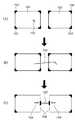
アプリケーション121は、コンテナの辺の状態を表現するために、実線(アイテム503)あるいは点線(504)を用いて辺を表すとともに、アンカー(辺の近くに描画された506、507、509によって示されるような線、形状、アイコン。)、ハンドル(移動、修正するために領域の辺上あるいは近傍に描画されたコントロール点、502)、スライダー(辺の両側に描画された短い並行線、図4の413)、拡縮アイコン(505)、色を用いる。 The
図5(A)〜(D)に示されるコンテナ表示方法のルールは以下の通りである。
(1)それぞれの辺を固定するために、実線で描画する。
(2)幅が固定の場合は、左と右の辺を実線で描画する。
(3)高さが固定の場合は、上と下の辺を実線で描画する。
(4)軸は描画しない。
(5)(1)〜(3)によって描画されていないそれぞれの辺の近くには拡縮アイコンが描画され、それらの辺を点線で描画する。
(6)垂直辺と水平辺、あるいは垂直軸と水平軸のそれぞれのペアで、もし両者が固定なら、それらの交差点にアンカーが描画される。
(7)それぞれの固定辺で、もし辺のどこにもアンカーが描画されていなければ、エッジの中央にスライダーが描画される。
(8)垂直及び水平辺、あるいは垂直及び水平軸のそれぞれのペアで、アンカーやスライダーが描画されていない場合、それらの交差点にハンドルが描画される。The rules for the container display method shown in FIGS. 5A to 5D are as follows.
(1) Draw with solid lines to fix each side.
(2) When the width is fixed, the left and right sides are drawn with solid lines.
(3) When the height is fixed, the upper and lower sides are drawn with solid lines.
(4) The axes are not drawn.
(5) An enlargement / reduction icon is drawn near each side not drawn by (1) to (3), and those sides are drawn by dotted lines.
(6) For each pair of vertical side and horizontal side, or vertical axis and horizontal axis, if both are fixed, an anchor is drawn at the intersection.
(7) For each fixed side, if no anchor is drawn anywhere on the side, a slider is drawn at the center of the edge.
(8) If anchors and sliders are not drawn on each pair of vertical and horizontal sides or vertical and horizontal axes, a handle is drawn at the intersection of them.
ルール(1)、(2)、(3)で定義された線は、前述したように固定あるいは制限されているため実線で描画される。ルール(5)のように、可変の辺は、点線で描画される。ルール(6)、(7)、(8)で定義された固定された点は、アンカーを表示し、いくつかの固定された辺はスライダーを表示し、他はハンドルを表示する。 The lines defined by the rules (1), (2), and (3) are drawn as solid lines because they are fixed or restricted as described above. As in rule (5), the variable side is drawn with a dotted line. Fixed points defined in rules (6), (7), and (8) display anchors, some fixed edges display sliders, and others display handles.
上記のルールは、ユーザにより後で設定された制約が優先される。つまり、後で別の制約が設定された場合、上記のルールが描画されるべき辺に影響すれば、実線や点線の描画内容が変更されることになる。 The above rules are given priority over constraints set later by the user. That is, when another constraint is set later, if the above rule affects the side to be drawn, the drawn content of the solid line or the dotted line is changed.
可変の辺が描画される場所は、コンテナのコンテンツに依存する。後に説明するように、ドキュメントテンプレートにコンテンツがマージされて、ユーザインターフェースで可視になることを意味する、『動的な校正処理』が使われる。なお、ユーザインターフェースにおける可変の辺の描画位置を別の手段を用いて決定してもよい。例えば、すべてのドキュメントで平均化されたサイズのコンテナ(平均化されたコンテンツエリア)を用いて可変の辺を描画する位置が決定されてもよい。 The location where the variable side is drawn depends on the content of the container. As will be explained later, “dynamic proofing” is used, which means that content is merged into a document template and made visible in the user interface. Note that the drawing position of the variable side in the user interface may be determined using another means. For example, a position where a variable side is drawn may be determined using a container (averaged content area) having an averaged size in all documents.
これらのコンテンツ表現は、コンテナの各辺の状態を表示するグラフィカルな手段を提供する。その表現の解釈は下記のとおりである。
(1)図4の410の辺のように、点線はコンテナのコンテンツに依存してドキュメント内の辺の位置が変化することを意味する。
(2)実線は、固定されている(辺414)、あるいはコンテナの幅・高さが固定されている(コンテナ408では4辺が実線であり、両方が固定されている)ために制限された辺であることを意味する。
(3)アンカーは辺および軸が交差した場所が固定されていることを意味する。それゆえ、アンカー点は、すべてのドキュメントの水平、垂直位置で現れることになる。アンカーは当然固定される。図4のアイコン409は、辺414の交差する位置が固定されていることを意味しているアンカーアイコンの例である。
(4)スライダーは関係付けられた辺の長さが固定されているが、並行移動する可能性があることを意味する。例えば、図4でスライダー413はコンテナ408に流し込まれたコンテンツデータが、ドキュメント内で特定のダイアグラムで表される位置の、左あるいは右に表示されるかもしれない。例えば、コンテナ408と関連付けられている(リンク設定されている)コンテナ407に流し込まれるデータの画像サイズもしくはテキスト量が少ない場合は、コンテナ407のサイズが小さくなる。そのため、コンテナ408は、左方向にスライド(並行移動)してレイアウトされて表示されることになる。また、コンテナ407のサイズが大きくなる場合は、逆にコンテナ408は右方向にスライドしてレイアウトされることになる。These content representations provide a graphical means for displaying the state of each side of the container. The interpretation of the expression is as follows.
(1) Like the
(2) The solid line is limited because it is fixed (side 414) or the width and height of the container are fixed (in
(3) The anchor means that the place where the side and the axis intersect is fixed. Therefore, the anchor point appears at the horizontal and vertical positions of all documents. The anchor is naturally fixed. The
(4) The slider has a fixed side length, which means that it may move in parallel. For example, in FIG. 4, the
これらのアイコン・辺のいくつかあるいは全ては、どのツール、どのコンテナを選択・ハイライトあるいはアクティブにするかによって、描画されたりされなかったりする。一般的に、コンテナの辺・アイコンはドキュメントテンプレートのデザインの手助けであるため、印刷物には描画されない。 Some or all of these icons / edges may or may not be drawn depending on which tool, which container is selected, highlighted or activated. In general, the sides and icons of a container are not drawn on a printed matter because they help to design a document template.
なお、前述したように、コンテナの幅・高さの基本値・最小値・最大値の基本パターンの設定は、副次的なダイアログウインドウに表示される。 As described above, the basic pattern setting of the basic value, minimum value, and maximum value of the width / height of the container is displayed in a secondary dialog window.
図5の(A)で、コンテナ501は、幅・高さの両方が固定されていない(可変である)。固定された辺503は実線で表現され、可変の辺504は点線で表現されている。拡縮アイコン505は、隣接する辺504が可変であることを示す。他の形態のインジケータを代わりにあるいは追加的に用いてもよい。 In FIG. 5A, the width and height of the
図5の(B)において、コンテナ501は幅・高さ両方が可変である。アンカーアイコン506が、交差している両方の辺503の角の位置が固定されていることを明示的に表すべく追加されている。 In FIG. 5B, the
図5の(C)において、コンテナ501は、コンテナの幅及び高さの両方が可変であり、任意のアンカーアイコン507で示されるような中心点の周りを平等に広がるという状態を示している。すなわち、コンテナ501はアンカーアイコン507を中心に拡大あるいは縮小が可能である。ここでの拡大/縮小は、アンカーアイコン507の位置が常にコンテナ501の中心点となるようにレイアウト調整される。 In FIG. 5C, the
図5の(D)において、コンテナ501は、上辺508が固定されているが、幅・高さの両方が可変である。上辺508の中心に位置付けられて示されるアンカーアイコン509は、固定されている。そしてコンテナ501の左辺・右辺は、アンカーアイコン509を通って垂直な中心軸(垂直軸)の周りを、拡大・縮小する。 In FIG. 5D, the
[リンク]
リンクは、コンテナとコンテナの関連を示している。関連とはコンテナ間の距離を示しており、リンクによって関連付けられたコンテナ同士は、互いのレイアウト変更の影響を受けてレイアウトを計算する。図4の412で示されているものがリンクであり、図4ではコンテナ407と408とを関連づけている。リンクの設定方法および、リンクで関連付けられたコンテナのレイアウト計算方法については、後述する。[Link]
The link indicates the relationship between containers. “Relation” indicates a distance between containers, and containers associated by a link are affected by each other's layout change and calculate a layout. What is indicated by 412 in FIG. 4 is a link. In FIG. 4,
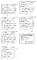
[リンクの設定方法]
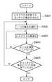
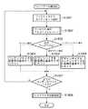
次に、コンテナ同士を関連付けるためのリンクの設定について説明する。図6はリンクの設定方法を示したフローチャートである。また図7の(A)〜(C)はリンク設定時のユーザインターフェース(UI)の遷移例を示している。図6,図7(A)〜(C)を用いてコンテナにリンクを設定する方法について説明する。なお、本願に記載されているフローチャートの各ステップの処理は、情報処理装置(ホストコンピュータ)が有するプロセッサ135によって実行されることとなる。[Link setting method]
Next, setting of a link for associating containers will be described. FIG. 6 is a flowchart showing a link setting method. 7A to 7C show transition examples of the user interface (UI) at the time of link setting. A method for setting a link in a container will be described with reference to FIGS. 6 and 7A to 7C. In addition, the process of each step of the flowchart described in this application will be performed by the
まず、ステップS601において、レイアウト編集アプリケーション121は、ユーザインターフェース画面のワークエリア306上に編集すべく選択されたドキュメントテンプレートを表示する。リンクを設定するためには、リンクを設定するためのコンテナ(最低2つ)がドキュメントテンプレート上に作成されている必要がある。図7(A)〜(C)では、ステップS601で2つのコンテナを作成してリンクを設定する場合のユーザインターフェースの遷移例を示している。 First, in step S601, the
次に、ステップS602において、レイアウト編集アプリケーション121は、前述したリンクツールが選択状態(図4のボタン406をクリックすることにより選択状態となる)になったかを判断する。リンクツールが選択上体でなければ、必要に応じて他の各種処理を実行し(ステップS609)、ステップS602に戻る。 Next, in step S602, the
図7の(A)において、コンテナ701と702はすべて固定されている辺で構成されているものとする。また、703と704は、図4の409と同じであり、アンカーを意味する。705はマウスポインタを意味している。さて、リンクツールが選択状態となっている間に、ユーザはリンクを設定する2つのコンテナのうちの一方(コンテナ701とする)をクリックして選択する。この操作に応じて、レイアウト編集アプリケーション121のユーザインターフェース103は第1のコンテナが指定されたことを認識し(ステップS603)、選択されたコンテナを特定する情報をメモリ136に保持する。また、以降のマウスカーソルの移動に応じた軌跡を画面に表示するようにする(ステップS604)。例えば、図7の(B)における線分706は、図7の(A)の状態におけるクリック位置と現在のマウスカーソルの位置とを結んだ線を示しており、このUIによりどの位置にリンクが設定されるのかをユーザに明示することができる。 In FIG. 7A, it is assumed that the
次に、ユーザは、図7の(B)で示されるように、もう一方のコンテナ(コンテナ702)までマウスポインタを移動してクリックする。この操作に応じて、ユーザインターフェース103は第2のコンテナが指定されたことを認識する(ステップS605)。そして、レイアウト編集アプリケーション121は、ステップS604で保持した第1のコンテナと、ステップS605で指定が認識された第2のコンテナとの間にリンクを設定する(ステップS606)。 Next, as shown in FIG. 7B, the user moves the mouse pointer to the other container (container 702) and clicks it. In response to this operation, the
こうして、ユーザにより選択された2つのコンテナ701,702の間にリンクが設定されると、リンクUI707が表示される(ステップS607)。更に、このリンク設定を受けて、コンテナの表示状態は図7の(C)の状態になる(ステップS608)。すなわち、リンクが設定されたことにより、コンテナのUIが自動的に変更される。ここでは、リンクによって関連付けられた辺が可変となり、点線で示される。図7の(C)において、708は点線で示されている辺であり、前述した通り可変の辺を示すものである。 Thus, when the link is set between the two
なお、図7の(C)のようなコンテナの辺の状態の変化は、リンクを設定したことによりコンテナの辺を可変にする必要が生じたことにより自動的に実行されたものである。これは、リンクを設定したにもかかわらず全ての辺が固定であるという矛盾の発生を防ぐことを目的としている。また、709は図5の(A)〜(D)の505と同じで、リンクを設定したことにより、コンテナが変化できる方向をユーザに視覚的に示したマークである。また、図7の(C)の例では、左のコンテナの右辺と右のコンテナの左辺が可変な状態へ変化したが、これは一例であり、たとえば、右コンテナが図4の413で示したスライダーを持つ設定に変化してもかまわない。 Note that the change in the state of the container side as shown in FIG. 7C is automatically executed when it is necessary to make the side of the container variable by setting the link. This is intended to prevent the occurrence of a contradiction that all sides are fixed despite the link being set. 709 is the same as 505 in FIGS. 5A to 5D, and is a mark that visually indicates to the user the direction in which the container can be changed by setting a link. In the example of FIG. 7C, the right side of the left container and the left side of the right container have changed to a variable state, but this is an example. For example, the right container is indicated by 413 in FIG. You can change the setting to have a slider.
<レイアウトエンジンによるレイアウト計算処理>
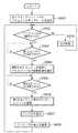
[レイアウト計算方法(全体フロー)]
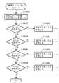
本実施形態のレイアウト編集アプリケーションは、レイアウトモードとプレビューモードに分けられる。レイアウトモードは、ユーザインターフェース103を用いてコンテナを作成し、そのコンテナ間に関連付け(リンク設定)を行ってレイアウトを作成するモードである。プレビューモードは、レイアウトエンジン105により、作成したレイアウトにデータソースの各レコードを挿入して、実際にレコードが挿入された後のレイアウト結果をプレビューするモードである。このプレビューモードにおいて、実際のレコードが有するコンテンツデータが挿入され、レイアウトを計算する。ただし、プレビューモードは、表示上でのレイアウト計算である。実際に印刷する場合においても、レイアウトエンジン105が各コンテナにデータを挿入してレイアウトを計算するが、その際の計算方法はプレビューモードと同じである。なお、コンテンツデータを流し込むべきコンテナに優先順位が設定されている場合は、該優先順位に従ってレイアウト計算を行うこととなる。優先順位に従うレイアウト計算の一例として、優先順位の高いコンテナに流し込まれるコンテンツデータは、できる限りオリジナルサイズ(元のデータサイズ)で表示することが考えられる。<Layout calculation processing by layout engine>
[Layout calculation method (overall flow)]
The layout editing application of this embodiment is divided into a layout mode and a preview mode. The layout mode is a mode in which containers are created using the
図8はレイアウト計算のフローを示している。まず、プレビューモードが選択される(ステップS801)。プレビューモードになったら、レイアウト編集アプリケーション121は、ユーザにプレビューするレコードをデータソースより選択させ、選択されたレコードの各フィールドデータを各コンテナに挿入するよう決定する(ステップS802)。各コンテナへのフィールドデータの挿入が決定されると、レイアウト編集アプリケーション121は、そのレコードをレイアウトするための計算を行い、必要に応じてレイアウト調整を行う(ステップS803)。ステップS803におけるレイアウト計算の詳細については後述する。そして、レイアウト編集アプリケーション121は、ステップS803で計算されたレイアウトを表示する(ステップS804)。レイアウト編集アプリケーション121は、他のレコードについてもプレビューを行うかどうかをユーザの指示により判断する(ステップS805)。ステップS805で、他のレコードについてプレビューを行う必要がないと判断した場合は、プレビューモードを終了する(ステップS807)。他のレコードについてプレビューを行うのであれば、レイアウト編集アプリケーション121は、他のレコードを選択して再度レイアウト計算を行い、プレビューを行う(ステップS806)。 FIG. 8 shows a flow of layout calculation. First, the preview mode is selected (step S801). In the preview mode, the
なお、プレビューモードでなく印刷時においては、印刷するレコード全てについて順にレイアウトの計算を行う。したがって、ステップS804は存在せず、ステップS805は印刷するレコードを全て処理したかの判断を行う。ステップS803でレイアウト計算された結果を、描画出力して出力し、プリンタドライバを用いて印刷データとして生成し、プリンタに印刷データが出力される。この場合、全てのレコード(印刷すべく指定された全レコード)について印刷データの出力が終了した時点で本処理を終了することになる。 Note that when printing is performed instead of the preview mode, the layout is calculated in order for all records to be printed. Accordingly, step S804 does not exist, and step S805 determines whether all records to be printed have been processed. The result of the layout calculation in step S803 is output by drawing and is generated as print data using a printer driver, and the print data is output to the printer. In this case, the process is terminated when the output of the print data is completed for all the records (all records designated to be printed).
[レイアウト計算方法(詳細)]
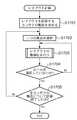
次に、上記ステップS803によるレイアウト計算の詳細について説明する。図9は本実施形態によるレイアウトの優先順位を設定しない場合のレイアウト計算の方法を示したフローチャートである。また、図10の(A)〜(C)はそのときのUI表示例を示した図である。図9はレイアウト計算の処理方法についてのみ説明するためのフローチャートであるため、バリアブルデータプリントの1レコードの印刷/プレビュー時のレイアウト計算方法に相当する。複数レコードの場合は、下記の処理が繰り返されることになる。[Layout Calculation Method (Details)]
Next, details of the layout calculation in step S803 will be described. FIG. 9 is a flowchart showing a layout calculation method when the layout priority is not set according to the present embodiment. 10A to 10C are diagrams showing examples of UI display at that time. FIG. 9 is a flowchart for explaining only the layout calculation processing method, and corresponds to the layout calculation method at the time of printing / previewing one record of variable data printing. In the case of multiple records, the following processing is repeated.
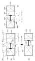
まず、レイアウト編集アプリケーション121は、レイアウトを計算するコンテナの集合を求める(ステップS901)。レイアウト計算は、関連付けられたコンテナを一つの集合として計算を行う。例えば図11を参照すると、ページ上に4つのコンテナがレイアウトされており、各コンテナに関連付けが設定されている。この場合、コンテナAとコンテナB、そしてコンテナCとコンテナDがリンクによって関連付けされている。したがって、コンテナA、Bが集合1、コンテナC、Dが集合2となる。すなわち、リンクによって接続されたコンテナ群を一つの集合として特定する。前述したように、1101はアンカー、1102は固定された辺、1103はコントローラー、1104は可変の辺の変化方向を示している矢印、1105は可変の辺、1106はリンク、そして1107はスライダーを示している。 First, the
次に、レイアウト編集アプリケーション121は、ステップS901で求めたコンテナの集合から、レイアウトを計算するために一つを選択する(ステップS902)。そして、選択したコンテナの集合について、レイアウトの計算を行う。まず、選択したコンテナの集合に含まれる可変要素である2つのコンテナ(A,B)について、流し込まれるデータの画像サイズもしくはテキスト量から各コンテナがなにも制約を受けない場合の大きさを計算する。具体的には、レイアウト編集アプリケーション121は、コンテナAが画像データ用コンテナであるか、テキスト用コンテナであるかを判断する。この判断は、前述したように、コンテナに対して設定されている属性により判断できる。次に、レイアウト編集アプリケーション121は、コンテナAに流し込まれるデータを読み込む。コンテナAが画像データ用コンテナである場合は、その画像データのサイズ(幅、高さのピクセル数、および解像度)がコンテナAの制約を受けない場合の大きさになる。また、コンテナAがテキスト用コンテナである場合は、そのテキストデータの文字数と、コンテナAのコンテナ属性で指定されている文字属性に基づいて、コンテナAに流し込まれるべきデータ量が計算できる。尚、文字属性とは、フォントタイプ、フォントサイズ、文字ピッチ、行ピッチなどである。ここで、テキスト用コンテナの場合は、コンテナAの縦横比の制約を考えないと決定できないため、制約を当てはめる。図11の例では、コンテナAは、左上および左下の角にアンカーが設定されているため、高さ(縦方向)が固定となる。よって、レイアウト編集アプリケーション121は、コンテナAの基本パターンとして設定されている幅(横方向)のコンテナAに、計算したデータ量(テキスト量)の文字を流し込めるか否かを判断する。すべて流し込めると判断された場合は、コンテナAは、基本パターンで設定されているサイズ(幅、高さ)に変更はない。また、すべて流し込めないと判断された場合はサイズ変更を行う。図11の例では、コンテナAは、アンカー設定により高さが固定であるため、横方向に伸びることになる。ここで、レイアウト編集アプリケーション121は、コンテナAの幅がどれだけになると、計算したデータ量の文字を流し込めるかを計算し、コンテナAのサイズを算出する。 Next, the
次に、レイアウト編集アプリケーション121は、レイアウトされるコンテナのサイズが、実際のコンテンツのサイズとできる限り差が少なくなるように、レイアウトの最適化を行う(ステップS903)。レイアウトの最適化は、動的にサイズを変化することが可能なように関連付けられたコンテナにおいて、それぞれに挿入されるコンテンツのサイズとレイアウトされるサイズとの差が、できる限り同じになるように行われる。レイアウト編集アプリケーション121は、ステップS902で算出したコンテナの集合のサイズ、つまりコンテナAとコンテナBとリンク1106(ここでは固定リンク)の合計サイズを求める。そして、この合計サイズと、基本レイアウトにおける当該コンテナの集合のサイズ(図11の例ではコンテナAとコンテナBのそれぞれのアンカーアイコンの距離に相当する)との差を求める。コンテナAやコンテナBの幅が大きくなると前ステップで計算されている場合は、差分値が発生する。レイアウト編集アプリケーション121は、この差分値をコンテナの集合の各要素に均等に分配することでレイアウト調整を行う。 Next, the
レイアウト編集アプリケーション121は、レイアウトの最適化を行い、ルールに違反していた場合は、再度ルールを違反しないように計算をする(ステップS904)。ここで記述したルールとは、レイアウト作成時にユーザによって設定される制限であり、コンテナのサイズの可変範囲や位置の制限、可変リンクの場合はリンクの長さの変化の制限などである。ルールを違反しないようにレイアウトが計算されたら、その集合のレイアウトは完成される。そして、ステップS902〜S904の処理をページ上のすべての集合について施し、レイアウト編集アプリケーション121は、ページ全体のレイアウトを計算する(ステップS905)。 The
図10の(A)〜(C)は優先順位の設定なしでのレイアウト時のUI例である。 10A to 10C are examples of UIs at the time of layout without setting priority.
図10の(A)は、あるレコードが挿入されレイアウトが決定されている状態を表している。1001と1002はアンカー、1003と1004は固定された辺、1005は可変の辺、1006は可変の辺の変化方向を示している矢印、1008はリンクをそれぞれ示している。この状態において、レコードを変更し、異なったサイズのコンテンツを挿入する。図10の(B)は図10の(A)の状態に新しいコンテンツのサイズを重ねて示している。1009はそれぞれのコンテナに挿入されるコンテンツサイズを表している。そして、レイアウト計算が行われる。図10の(C)はレイアウト計算された結果を示している。計算後の各コンテナのサイズは、実際挿入されるコンテンツのサイズと同等に差異があるように計算され、且つ前述したルールを違反しないように計算される。図10の(C)で示されるように、図10の(B)で示した挿入されるコンテンツサイズ(1009)と計算後のコンテンツサイズ(1010)は、双方において同等な差異がある。 FIG. 10A shows a state in which a certain record is inserted and a layout is determined. 1001 and 1002 are anchors, 1003 and 1004 are fixed sides, 1005 is a variable side, 1006 is an arrow indicating the change direction of the variable side, and 1008 is a link. In this state, the record is changed and contents of different sizes are inserted. FIG. 10B shows the size of the new content superimposed on the state of FIG.
図10の(A)〜(C)のような横方向のみのレイアウト計算の場合は同等の差異をもってレイアウト計算を行う処理だけで問題は生じない。しかしながら、図31のように縦方向および横方向を考慮したレイアウト計算を行わなければならない場合、同等の差異をもってレイアウト計算を行う処理だけでは対応できなくなる可能性がある。
横方向と縦方向の2次元的なレイアウトを扱う図31の場合、図9のレイアウト計算方法を用いて、まず横方向に調整を行い、後に縦方向に調整を行う。すなわち、コンテナ3101と3102の間で、上述した手順で設定値Dに収まるようレイアウト調整を行い、その後、コンテナ3102と3103の間で設定Gに収まるようレイアウト調整を行うこととなる。In the case of layout calculation only in the horizontal direction as shown in FIGS. 10A to 10C, there is no problem if only the layout calculation is performed with the same difference. However, when layout calculation in consideration of the vertical direction and the horizontal direction as shown in FIG. 31 must be performed, there is a possibility that it cannot be handled only by the process of performing the layout calculation with the same difference.
In the case of FIG. 31 that handles a two-dimensional layout in the horizontal direction and the vertical direction, the layout calculation method in FIG. 9 is used to make adjustments in the horizontal direction first and then make adjustments in the vertical direction. That is, the layout adjustment is performed between the
しかし、横方向に調整を行い、後に縦方向に調整を行うという調整方法では、ユーザが所望とする基本レイアウトからずれたレイアウト結果になることが想定される。 However, with the adjustment method in which adjustment is performed in the horizontal direction and then in the vertical direction, a layout result deviating from the basic layout desired by the user is assumed.
そのため、各コンテナについて、基本パターン(レイアウト設計時のコンテナサイズやコンテナの縦横比など)からなるべくずれないようにする。そのために、例えば、以下の方法が考えられる。基本パターンの幅とレイアウト調整後の幅の差の2乗と、基本パターンの高さとレイアウト調整後の高さの差の2乗との和を求め、これをすべてのコンテナについて算出する。そして、レイアウト編集アプリケーション121は、各コンテナの2乗の和(横方向+縦方向)の合計値が最小となるように、それぞれのコンテナの幅と高さを算出してレイアウト調整を行う。このように最小2乗法を用いてレイアウト調整を行うことにより、ユーザが当初設定した基本レイアウトから大きく外れることがなく、全体としてバランスのとれた最終レイアウトを決定することができる。 Therefore, for each container, the basic pattern (the container size at the time of layout design, the aspect ratio of the container, etc.) should be kept as small as possible. For this purpose, for example, the following method can be considered. The sum of the square of the difference between the width of the basic pattern and the width after layout adjustment and the square of the difference between the height of the basic pattern and the height after adjustment of the layout is calculated, and this is calculated for all containers. Then, the
なお、コンテナ間には後述する可変リンクが設定されているため、流し込まれるコンテンツデータのサイズに応じて後述するようにリンクサイズは変更する。本願記載のレイアウト編集アプリケーションはこのようなレイアウト調整ユニットを備えることにより、割り当てられたデータサイズに応じて複数の部分表示領域(コンテナ)の配置位置を調整することが可能となる。 Since a variable link described later is set between the containers, the link size is changed as described later according to the size of the content data to be inserted. By providing such a layout adjustment unit, the layout editing application described in the present application can adjust the arrangement positions of a plurality of partial display areas (containers) according to the allocated data size.
また、上記記載ではレイアウト調整アルゴリズムの一例として最小2乗法を用いることを挙げたが、3乗や4乗など所定の操作によりレイアウト調整アルゴリズムを切り替えることを可能にしても構わない。なお、具体的なレイアウト計算方法は、図32から図34を用いて後述する。 In the above description, the least square method is used as an example of the layout adjustment algorithm. However, the layout adjustment algorithm may be switched by a predetermined operation such as a third power or a fourth power. A specific layout calculation method will be described later with reference to FIGS.
[長さが可変のリンクの設定]
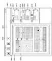
図12では可変リンクの設定のためのユーザインターフェースを表している。図4と同様にアプリケーションウインドウ301とツールバー303がある。図12の状態では、ドキュメントテンプレート309上にコンテナ1203とコンテナ1204が存在する。それぞれのコンテナはアンカーアイコン1201、アンカーアイコン1202と固定された辺1205、辺1206を含んで構成されている。コンテナ1203と1204の間には可変サイズのリンク1209があり、コンテナ1203とコンテナ1204を結んでいる。コンテナ1203とコンテナ1204の間にはリンクが設定されているのでそれぞれの右辺1207と左辺1208は点線で表現されている。このため各コンテナにインジケーター1210、インジケーター1211が表示され、それぞれ辺1207と辺1208が可変であることを示している。[Link settings with variable length]
FIG. 12 shows a user interface for setting a variable link. Similar to FIG. 4, there are an
また、図14は、リンク設定手段におけるユーザインタフェース画面であり、リンク1209の情報をセットするためのダイアログウインドウ1401の例である。このダイアログは、タイトルバー1402、ツールボタン1403、ダイアログウインドウの開閉を行うボタン1404、各種の情報をセットするエリア1409で構成されている。このダイアログウインドウではリンクタイプが可変長(1407)のリンクであるか、あるいは固定長(1406)のリンクであるかの択一的な選択を行える。リンクタイプが可変の場合にはリンクの長さの最小値(Min.Distance1410)、最大値(Max.Distance1412)、ならびに基準値(Distance1411)が設定できる。図14のダイアログ1401は、たとえば、図6,図7の(A)〜(C)で説明したリンクの設定操作によって2つのコンテナ間にリンクを設定した後に、この設定されたリンクをクリック等の操作によって選択したときに表示される。あるいは、リンクを設定した直後に、当該リンクに関するダイアログウインドウ1401が自動的に表示されるようにしてもよい。ここで各コンテナ間の距離の基準値1411は、データを流し込んだ際に各コンテナのサイズが変更されない場合に用いられるリンクの長さである。 FIG. 14 shows an example of a
図13は、本実施形態のユーザインターフェース103による可変リンクの設定手順を説明するフローチャートである。例えば図11のコンテナAとコンテナBの間に図6、図7の(A)〜(C)で説明した手順でリンクを張ると、まず固定サイズのリンクが張られる。そして、このリンクを選択して図13に示す処理を実行することにより、当該リンクを固定サイズのリンク1106(図11)の状態から可変サイズのリンク1209(図12)へと遷移させることができる。 FIG. 13 is a flowchart for explaining a variable link setting procedure by the
まず、マウスにより所望のリンク(たとえばリンク1106)を選択状態とし、リンクプロパティを表示させるための所定の操作が行われる。すると、レイアウト編集アプリケーション121のユーザインターフェース103は、リンクプロパティの表示指示の入力として認識する(ステップS1301)。リンクプロパティの表示指示を認識すると、選択状態のリンク(以下、対象リンクという)に対応したプロパティダイアログウインドウ1401(図14)が表示される。次に、ユーザインタフェース103は、リンクプロパティを表示する(ステップS1302)。なお、リンクの選択操作としては、コンテナの基本パターンの設定時と同様に、マウスの右クリックあるいはキーボードの特定のキーの操作等、いかなるものであってもよい。 First, a desired link (for example, link 1106) is selected with the mouse, and a predetermined operation for displaying link properties is performed. Then, the
ステップS1302で表示されるダイアログウインドウ1401には選択されたリンクの現在の状態が示される。本例では、リンク1106が選択されたので、この段階ではリンクサイズは固定であり、Link Type1405においては、固定長を示すFixed Length1406が選択されている。 A
このダイアログウインドウ1401においてリンクを固定サイズから可変サイズに変更するために、Link Type1405においてリンクサイズを可変に設定するためのFlexible Length1407を選択する。これによりLinkDistance1408内に配置されているMax. Distance1412、Min. Distance1410、Distance1411が有効になり、数値の設定が可能となる。ユーザは、リンクの可変サイズを設定するために、そのリンクの長さの最大値をMax.Distance1412に、最小値をMin. Distance1410に、現在の値をDistance1411に設定することになる。 In order to change the link from a fixed size to a variable size in this
設定を終えると、ユーザは一般的なダイアログウインドウ開閉ボタン1404によって当該設定の適用を指示する。ユーザインターフェース103はこの指示を検出すると、ステップS1303からステップS1304以降へ処理を進め、当該対象リンクに上記設定状態を反映させる。 When the setting is completed, the user instructs application of the setting using a general dialog window open /
すなわち、まず、ステップS1304において、レイアウト編集アプリケーション121は、対象リンクが固定サイズか可変サイズかを判定する。固定サイズが指定されていればステップS1308へ進み、対象リンクを「固定サイズ」に設定し、ステップS1307で対象リンクの表示状態を「固定リンク」を表す「実線」とする。 That is, first, in step S1304, the
一方、ステップS1304において、可変サイズが指定されていれば、ステップS1305へ進み、レイアウト編集アプリケーション121は、対象リンクを「可変サイズ」に設定する。そして、ステップS1306にて、上記ダイアログウインドウ1401によって設定された対象リンクの現在値(基準値)、最大値、最小値を登録する。その後、ステップS1307で対象リンクの表示状態を「可変リンク」を表す「点線」とする。この結果、図12のリンク1209に示すような状態にリンクのUI表示が変化する(ステップS1306)。以上のダイアログウインドウ701の設定情報はメモリに格納される。 On the other hand, if a variable size is specified in step S1304, the process advances to step S1305, and the
なお、Distance1411に設定される現在の値には、現在のレイアウトとして配置されているコンテナの間の距離がデフォルト値として自動的に入力されるようにしてもよい。 Note that the distance between containers arranged as the current layout may be automatically input as the default value for the current value set in
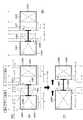
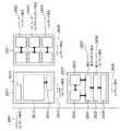
図15は固定サイズのリンクを使用した場合であり、図12に記載されている基本レイアウトにコンテンツを流し込んだレイアウト結果を示している。なお、図12のリンク1209は可変リンクとなっているが、固定リンクが設定されているものと想定する。レイアウト計算方法は前述したとおりに従って行われる。 FIG. 15 is a case where a fixed-size link is used, and shows a layout result in which content is flowed into the basic layout described in FIG. The
例えば図12においてコンテナ1203とコンテナ1204にそれぞれ違ったサイズのイメージデータ(1504および1505)が挿入された場合を考える。 For example, consider a case where image data (1504 and 1505) having different sizes are inserted into the
この場合、それぞれのコンテナはデータの大きさを最適とみなし、コンテナ1203は挿入されたイメージサイズになる枠1504(最適コンテナサイズ)に近づこうと右方向へサイズを変更しようとする。同様にコンテナ1204は挿入されたイメージサイズになる枠1505(最適コンテナサイズ)に近づこうと左方向へサイズを変更しようとする。 In this case, each container regards the data size as optimum, and the
しかしコンテナ1203とコンテナ1204はアンカー1201とアンカー1202によってそれぞれ左辺1212と右辺1213の移動ができず、上記のようにサイズを変更しようとすると両者の間隔を狭めるしかない。しかしながら、コンテナ間には固定サイズのリンク1503が設定されており、レイアウト計算時にその長さ維持されるため、コンテナ1203とコンテナ1204のサイズが変更されることになる。 However, the
その結果、コンテナ1203とコンテナ1204はデータの縦横比に合わせた最適なサイズを確保することが出来ず、最終的に図15に示すように、最適なサイズ(枠1504、枠1505)よりも小さくなってしまう。すなわちリンク1503のサイズが固定であるためコンテナ1501とコンテナ1502は最適サイズを達成できない(図15において、各コンテナ内の一点差線で示した範囲がデータの持つ縦横比である)。 As a result, the
一方、図16は図15と同様の状態でリンクを可変サイズにした場合を示している。この場合、上記の例でコンテナ1203とコンテナ1204の間には図示の通り可変サイズのリンク1209が設定されている。したがって、コンテナ1203とコンテナ1204のサイズが変更される際には、リンクサイズが縮まることでコンテナ1203とコンテナ1204のサイズを図15の例より大きくすることができる。この結果、挿入されるデータサイズに合わせた最適なサイズを達成できる、あるいはより挿入データサイズ(最適サイズ)に近いコンテナの枠を設定することが出来る。図16はこの結果を示しており、可変リンク1209はレイアウト計算の結果、可変リンク1603に示されるようなサイズ状態となる。なお、この場合コンテナ1203とコンテナ1204はそれぞれ最適なサイズ(データサイズに合った大きさ)になっている。 On the other hand, FIG. 16 shows a case where the link is made variable in the same state as FIG. In this case, a variable-
[複数種類のレイアウト計算方法を用いた自動レイアウト処理]
<全体フロー>
次に、本実施形態による、複数種類のレイアウト計算方法を用いた自動レイアウト処理について説明する。[Automatic layout processing using multiple types of layout calculation methods]
<Overall flow>
Next, automatic layout processing using a plurality of types of layout calculation methods according to the present embodiment will be described.
本実施形態では、複数のコンテナを有するドキュメントテンプレートのレイアウトを、これら複数のコンテナの各々に流し込まれるコンテンツデータに応じて動的に変更する自動レイアウト処理を説明する。図17は本実施形態による自動レイアウト処理の全体的な処理の流れを示すフローチャートである。まず、ステップS1701でレイアウトを計算するコンテナの集合を求める。ここで言うコンテナの集合とは、リンクで直接或いは間接に相互に結ばれているコンテナ全てを要素とする集合体のことであり、リンクセットともいい、前述したようにリンクにより関連付けられているコンテナ群を指す。このように、ステップS1701では、レイアウト全体に存在するリンクセットを見つける処理が行なわれる。 In the present embodiment, an automatic layout process will be described in which the layout of a document template having a plurality of containers is dynamically changed according to content data that is flowed into each of the plurality of containers. FIG. 17 is a flowchart showing the overall processing flow of the automatic layout processing according to this embodiment. First, in step S1701, a set of containers whose layout is calculated is obtained. The collection of containers referred to here is a collection of all containers directly or indirectly connected to each other by links, and is also called a link set. As described above, containers are linked by links. Refers to a group. As described above, in step S1701, processing for finding a link set existing in the entire layout is performed.
次に、ステップS1702ではステップS1701で求めたリンクセットから1つのリンクセットが選択される。そしてステップS1703において、ステップS1702で選択された1つのリンクセットに関してレイアウトの最適化を行う。ステップS1703におけるレイアウトの最適化とは、レイアウト計算を行うということに等しく、この処理については「レイアウトの最適化フロー」にて、図18を参照して詳細に説明する。 Next, in step S1702, one link set is selected from the link sets obtained in step S1701. In step S1703, the layout is optimized for one link set selected in step S1702. The layout optimization in step S1703 is equivalent to performing layout calculation, and this process will be described in detail in the “layout optimization flow” with reference to FIG.
次にステップS1704ではルールを違反していないかについてチェックを行っている。ここで言うルールとはオフセットルールのことであり、オフセットルールとはレイアウトの制約のことである。レイアウトの制約とは、コンテナや可変リンクの最大値・最小値、またページ枠の位置などを対象としたものであり、レイアウト計算を行う上で破ってはいけないルールである。言い換えると、レイアウト計算はオフセットルールを破らない範囲内で行われることになる。ステップS1704においてルールを違反していると判定された場合はステップS1703に戻り、再度レイアウトの最適化を行うこととなる。ルールを違反していないと判定された場合は、ステップS1704からステップS1705へ進む。ステップS1705では、ステップS1701で見つけた全てのリンクセットについて上記処理(レイアウトの最適化)を終了したかどうかについて判断される。未処理のリンクセットがあればステップS1702へ戻り、別のリンクセットを選択し、レイアウトの最適化を行っていく。もし全てのコンテナ集合について計算が終了した場合は、レイアウト全体フローを終了する。 Next, in step S1704, it is checked whether or not the rule is violated. The rule here is an offset rule, and the offset rule is a layout restriction. Layout restrictions are for the maximum and minimum values of containers and variable links, the position of page frames, and the like, and are rules that must not be broken when performing layout calculations. In other words, the layout calculation is performed within a range that does not violate the offset rule. If it is determined in step S1704 that the rule is violated, the process returns to step S1703 and the layout is optimized again. If it is determined that the rule is not violated, the process advances from step S1704 to step S1705. In step S1705, it is determined whether or not the above processing (layout optimization) has been completed for all link sets found in step S1701. If there is an unprocessed link set, the process returns to step S1702, and another link set is selected to optimize the layout. If the calculation is completed for all container sets, the entire layout flow is terminated.
こうしてレイアウト全体フローを完了すると、図8のステップS804で示したようにプレビューとして表示したり、プリント出力のためのデータとして外部へ出力したりすることになる。 When the entire layout flow is completed in this way, it is displayed as a preview as shown in step S804 in FIG. 8 or output to the outside as data for print output.
[レイアウト最適化フロー]
図18は本実施形態によるレイアウト最適化処理を説明するフローチャートである。以下、同図を参照して本実施形態の最適化レイアウト処理を説明する。[Layout optimization flow]
FIG. 18 is a flowchart for explaining layout optimization processing according to this embodiment. Hereinafter, the optimized layout processing of this embodiment will be described with reference to FIG.
まず、ステップS1801で、レイアウト編集アプリケーションはステップS1702で選択されたリンクセット(集合)からコンテナを1つ選択する。詳細には、マウス等を用いて選択されたコンテナを入出力インタフェース143を介して認識することにより、ドキュメントテンプレート上のどのコンテナが選択されたかを認識することが可能となる。なお、S1801により選択されたコンテナは一時的にメモリ136に保持されることとなる。 First, in step S1801, the layout editing application selects one container from the link set (set) selected in step S1702. Specifically, by recognizing a container selected using a mouse or the like via the input /
次にステップS1802において、レイアウト編集アプリケーション121は、S1801により選択されたコンテナに適用するレイアウト調整アルゴリズムを取得する。これは、メモリ136或いは格納デバイス139によって保持されているアルゴリズム情報をパース(解析)することにより取得される。レイアウト調整アルゴリズム情報は図25等により後述するユーザインターフェースを用いて設定され、例えば図30(後述)に示されるようにメモリ136或いは格納デバイス139に保持される。ここではそのようなレイアウト調整アルゴリズム情報を探索し、ステップS1801で選択したコンテナに対してレイアウト計算を行うために適用すべきレイアウト調整アルゴリズムとして決定する。なお、ステップS1802の処理については、「適用アルゴリズムのパースフロー」にて、図19を参照して詳細に説明する。 In step S1802, the
ステップS1803において、レイアウト編集アプリケーション121は、ステップS1802におけるレイアウト調整アルゴリズムの探索結果に応じて処理を分岐する。ステップS1801で選択されたコンテナに適用すべきレイアウト調整アルゴリズムが「コンテンツ優先」であると判定した場合、処理はステップS1803からステップS1804に進む。ステップS1804において、レイアウト調整アルゴリズムは、ステップS1801で選択されたコンテナに挿入されるコンテンツ(データベースからの挿入データ)のサイズがそのコンテナの計算用の基準サイズであると設定し、メモリ136に一時的に保持する。例えばイメージであれば、当該イメージデータが有するサイズを計算用の基準サイズとする。また、テキストデータの場合は、文字数と、該テキストデータを流し込むべきコンテナの属性(テキストデータを反映する際のフォントタイプ、フォントサイズなどの文字属性)に基づいて、計算用の基準サイズが決定される。 In step S1803, the
又、レイアウト編集アプリケーション121は、ステップS1801で選択したコンテナに対する適用レイアウト調整アルゴリズムが「コンテナ・コンテンツ優先」だと判定した場合は、処理をステップS1805に進める。ステップS1805では、ステップS1801で選択されたコンテナ自身がデザインされた時(基本レイアウト時)のコンテナサイズがコンテナの計算用の基準サイズとして設定される。そして、当該コンテナに挿入されるコンテンツ(データベースからの挿入データ)のサイズと共に、設定された計算用の基準サイズをメモリ136に一時的に保持する。 If the
又、レイアウト編集アプリケーション121は、ステップS1801で選択されたコンテナに対する適用レイアウト調整アルゴリズムが「基本デザイン優先」だと判定した場合、処理をステップS1806に進める。ステップS1806では、ステップS1801で選択されたコンテナのデザインサイズ(基本レイアウト時のコンテナサイズ)をそのコンテナの計算用の基準サイズとして設定し、メモリ136に一時的に保持する。なお、本願では計算用の基準サイズの変わりに目標形状ということもある。 If the
ステップS1804〜S1806の終了後、ステップS1807に進み、全てのコンテナの適用レイアウト調整アルゴリズムをパースしたかどうかがチェックされる。パースを行っていないコンテナがある場合は、ステップS1801へ戻り、当該リンクセットから別のコンテナが選択され、選択されたコンテナの適用レイアウト調整アルゴリズムがパースされる。リンクセット内の全てのコンテナについてパースが終了したと判定された場合はステップS1808に進み、レイアウト再計算処理が行われる。レイアウト再計算処理とは、適用されたレイアウト調整アルゴリズムに従ってそれぞれのリンクセット内のレイアウト計算を行う処理である。ステップS1808の処理については後の「レイアウト再計算処理フロー」にて詳しく説明をする。
図18の処理により、レイアウト編集アプリケーションは、複数のレイアウトアルゴリズムからコンテナに適用すべきアルゴリズムを選択して、コンテナ毎に選択されたアルゴリズムに従ってレイアウト調整を実行することが可能となる。After step S1804 to S1806, the process proceeds to step S1807, where it is checked whether the applied layout adjustment algorithm for all containers has been parsed. If there is a container that has not been parsed, the process returns to step S1801, another container is selected from the link set, and the applied layout adjustment algorithm of the selected container is parsed. If it is determined that the parsing has been completed for all containers in the link set, the process advances to step S1808 to perform layout recalculation processing. The layout recalculation process is a process of performing layout calculation in each link set according to the applied layout adjustment algorithm. The processing in step S1808 will be described in detail in the “layout recalculation processing flow” later.
With the processing in FIG. 18, the layout editing application can select an algorithm to be applied to a container from a plurality of layout algorithms and perform layout adjustment according to the algorithm selected for each container.
[適用レイアウト調整アルゴリズムのパースフロー]
図19は、ステップS1801で選択されたコンテナに対して、ステップS1802で行われる適用レイアウト調整アルゴリズムのパースを示すフローチャートである。まず、ステップS1901においてレイアウト編集アプリケーション121は、ドキュメント指定アルゴリズムをコンテナの適用レイアウト調整アルゴリズムに設定する。つまり、デフォルトの設定としてドキュメントに設定されているレイアウト調整アルゴリズムを、とりあえずそのコンテナの適用アルゴリズムとして設定する。例えば、図30のようなレイアウト調整アルゴリズム情報においては、ドキュメントの階層に設定されている「コンテンツ優先」というレイアウト調整アルゴリズムが設定されることになる。[Perspective flow of applied layout adjustment algorithm]
FIG. 19 is a flowchart showing the parsing of the applied layout adjustment algorithm performed in step S1802 for the container selected in step S1801. First, in step S1901, the
次に、ステップS1902において、レイアウト編集アプリケーション121は、コンテナに直接指定されているレイアウト調整アルゴリズムがあるかをチェックする。詳細には、メモリ136にコンテナ属性が保持されており、該メモリ136を参照することにより、直接指定されているレイアウト調整アルゴリズムがあるか否かを判定することが可能となる。 Next, in step S1902, the
レイアウト編集アプリケーション121が、S1902においてコンテナに直接指定されているレイアウト調整アルゴリズムがあると判定した場合、ステップS1903に進み、その指定アルゴリズムを当該コンテナに設定し、本パース処理を終了する。 If the
当該コンテナに直接指定されているレイアウト調整アルゴリズムがない場合は、処理はステップS1904に進む。ステップS1904では、レイアウト編集アプリケーション121は、当該コンテナを含むエリア(ある一定の範囲)に対してレイアウト調整アルゴリズムが指定されているかをチェックする。ここで言うエリアとは、ユーザが任意に選択した範囲や、図18で説明したリンクセット(集合)を指すことができる。レイアウト編集アプリケーション121が、エリアに指定されているレイアウト調整アルゴリズムがあると判定した場合、ステップS1905に進み、その指定アルゴリズムを該エリア内の当該コンテナに設定し、パース処理を終了する。なお、エリアに対してレイアウト調整アルゴリズムが指定されていた場合、これらの情報についてもメモリ136等に保持されているため、レイアウト編集アプリケーション121が、メモリ136を参照することにより、S1904は判定可能となる。 If there is no layout adjustment algorithm directly specified for the container, the process advances to step S1904. In step S1904, the
エリアに指定されているレイアウト調整アルゴリズムがない場合はステップS1906に進む。ステップS1906では、レイアウト編集アプリケーション121は、当該コンテナに流し込まれるコンテンツデータを含むレコードにおいて、使用するレイアウト調整アルゴリズムが指定されているかをチェックする。例えば、レコード1ではこのレイアウト調整アルゴリズム、レコード2ではこのレイアウト調整アルゴリズムというようにレコード単位でレイアウト計算に使用するレイアウト調整アルゴリズムを変更することが出来る。なお、レコード単位に使用するレイアウト調整アルゴリズムが指定されている場合、これらの情報についてもメモリ136等に保持されている。このため、レイアウト編集アプリケーション1212が、メモリ136を参照することにより、ステップS1906の判定が実行可能となる。 If there is no layout adjustment algorithm specified for the area, the process advances to step S1906. In step S1906, the
レコードに指定されているレイアウト調整アルゴリズムがあればステップS1907に進み、現在のレコードの指定アルゴリズムをコンテナに設定し、パース処理を終了する。 If there is a layout adjustment algorithm specified for the record, the process advances to step S1907 to set the algorithm for specifying the current record in the container, and the parsing process ends.
レコードに指定されているレイアウト調整アルゴリズムがない場合はステップS1908に進む。ステップS1908では、レイアウト編集アプリケーション121は、当該コンテナを含むページ内で使用されるレイアウト調整アルゴリズムが指定されているかをチェックする。ここで言うページ内とはページ上にある全てのコンテナに適用するための設定であり、ページ単位に異なるレイアウト調整アルゴリズムを指定することが出来る。なお、ページ単位に使用するレイアウト調整アルゴリズムが指定されている場合、これらの情報についてもメモリ136等に保持されているため、レイアウト編集アプリケーション1212が、メモリ136を参照することにより、S1906は判定可能となる。ページに指定されているレイアウト調整アルゴリズムがあればステップS1909に進み、現在のページの指定アルゴリズムをコンテナに設定し、パース処理を終了する。ステップS1908においてページに指定されているレイアウト調整アルゴリズムがないと判定された場合は、S1902、S1904、S1906、S1908の判定処理により、全てにおいてNoと判定されたこととなる。この場合、レイアウト編集アプリケーション121は、S1901により設定したドキュメント指定アルゴリズムをドキュメント内のコンテナに適用して、フローを終了する。 If there is no layout adjustment algorithm specified in the record, the process advances to step S1908. In step S1908, the
以上のパース処理により、図30に示す階層構造の、下位階層に設定された状態が優先的にコンテナに設定されていくことになる。 Through the above parsing process, the state set in the lower hierarchy of the hierarchical structure shown in FIG. 30 is preferentially set in the container.
[再計算処理フロー]
図20は本実施形態によるレイアウト再計算処理(ステップS1808)を示すフローチャートである。[Recalculation process flow]
FIG. 20 is a flowchart showing the layout recalculation process (step S1808) according to this embodiment.
まず、ステップS2001で、レイアウト編集アプリケーション121は、マークを選択する。マークとはコンテナ枠線のことで、コンテナのどの辺を動かすのかを決めるために選択する。なお、ここで選択される枠線は、コンテナの移動可能な辺である。 First, in step S2001, the
そして、ステップS2002において、レイアウト編集アプリケーション121は、テンションの計算を行う。テンションとは計算用の基準サイズと現在のコンテナサイズの差に対応する。なお、計算用の基準サイズと現在のコンテナサイズの差の計算方法はレイアウト調整アルゴリズム毎に異なる。レイアウト計算においては、この差を縮めていく(テンションを小さくしていく)ことによってレイアウトを決定していく。また、計算用の基準サイズは上述した通り、適用されるレイアウト調整アルゴリズムに応じて変わるものであり、メモリ136に一時的に保持されている。さらに、現在のコンテナサイズについても一時的にメモリ136に保持されているため、レイアウト編集アプリケーションはS2002において、メモリ136を参照することによりテンションの計算を行うことが可能となる。 In step S2002, the
ステップS2003では、レイアウト編集アプリケーション121は、ステップS2002で計算したテンションに基づいてマークを移動する。なお、移動した後の位置情報(座標値など)およびマークの移動処理が終了したことは、メモリ136に保持される。 In step S2003, the
ステップS2004において全てのマークを選択したかをチェックしている。全てのマークとは全てのコンテナのエッジ(枠)のことであり、リンクセット内における全コンテナのテンション計算を行い、マークの移動が行われたか否かについてチェックする。S2003により、マークの移動処理が行われたものについては、移動処理終了であることがメモリ136に保持されているため、レイアウト編集アプリケーションがメモリ136を参照することにより判定可能である。なお、未選択のマークが存在するならば、ステップS2001に進み、未選択のマークを選択してステップS2002以降の処理を繰り返す。全てのマークを選択し終わっていた場合はフローを終了する。 In step S2004, it is checked whether all the marks have been selected. All marks are edges (frames) of all containers, and the tension of all containers in the link set is calculated to check whether or not the marks have been moved. With respect to those for which the mark movement processing has been performed in S2003, the fact that the movement processing has been completed is held in the memory 136, so that the layout editing application can determine by referring to the memory 136. If there is an unselected mark, the process proceeds to step S2001 to select an unselected mark and repeat the processing from step S2002. If all the marks have been selected, the flow ends.
[各種レイアウト調整アルゴリズムの計算方法]
次に、ステップS2002,S2003で実行されるいくつかのレイアウト調整アルゴリズムの計算方法の一例を説明する。なお、以下では一方向(横方向)にコンテナをレイアウト調整しているが、縦方向にレイアウト調整する場合も同様である。また2方向(縦横方向)にコンテナをレイアウト調整する処理に拡張できることが明らかであり、一つのアルゴリズム計算方法としては上述した最小2乗法を用いるものが挙げられる。また、コンテナのレイアウトを調整するためのレイアウト調整アルゴリズムは本実施形態で示されたものに限られるものではない。[Calculation methods for various layout adjustment algorithms]
Next, an example of several layout adjustment algorithm calculation methods executed in steps S2002 and S2003 will be described. In the following, the layout of the container is adjusted in one direction (horizontal direction), but the same applies to the layout adjustment in the vertical direction. In addition, it is clear that the process can be extended to a process for adjusting the layout of the container in two directions (vertical and horizontal directions), and one algorithm calculation method includes a method using the least square method described above. Further, the layout adjustment algorithm for adjusting the layout of the container is not limited to that shown in the present embodiment.
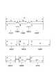
図21の(A)〜(C)はコンテンツ優先のレイアウト調整アルゴリズムを説明する図である。図21の(A)に示されるように、コンテナ2101とコンテナ2102が存在し、それらはリンク2103によって関連付けされている。それぞれのコンテナにはデータベースから挿入されるデータ(コンテンツ)が存在し、コンテナ2101にはコンテンツ2104、コンテナ2102にはコンテンツ2105が挿入されている。現在の各コンテナの幅サイズ(コンテンツ2104およびコンテンツ2105を挿入する前のコンテナの幅サイズ)はコンテナ2101が5、コンテナ2102が7、各コンテンツサイズの幅サイズはコンテンツ2104が8、コンテンツ2105が4である。 21A to 21C are diagrams for explaining a content-priority layout adjustment algorithm. As shown in FIG. 21A, there are a
コンテンツ優先のレイアウト調整アルゴリズムではこれらの情報を元に、レイアウト計算を行う。コンテンツ優先のレイアウト調整アルゴリズムでは上述した通りコンテンツサイズを計算用の基準サイズとみなし、コンテナサイズをレイアウト調整していく。レイアウト計算では現在のコンテナサイズ(コンテナ2101、コンテナ2102)と計算用の基準サイズ(コンテンツ2104、コンテンツ2105)との差(テンション)を縮めるよう現在のコンテナをレイアウト調整する。そして、このレイアウト調整によって、計算用の基準サイズに近づけようとする。 The content-priority layout adjustment algorithm performs layout calculation based on this information. In the content priority layout adjustment algorithm, as described above, the content size is regarded as a reference size for calculation, and the container size is adjusted for layout. In the layout calculation, the layout of the current container is adjusted so as to reduce the difference (tension) between the current container size (
図21の(B)はテンションの計算処理を図示している。図21の(B)に示されるように、コンテナ2101のテンションT1は8−5=3、コンテナ2102のテンションT2は7−4=3である。よってこのリンクセットのテンションの合計は6である。FIG. 21B illustrates a tension calculation process. As shown in FIG. 21B, the tension T1 of the container 2101 is 8−5 = 3, and the tension T2 of the container 2102 is 7−4 = 3. Therefore, the total tension of this link set is 6.
このテンションを減らすようにマークの移動を行った結果が図21の(C)に示されている。ここではコンテナ2101のサイズは8、コンテナ2102のサイズは4となっており、ともに計算用の基準サイズ(コンテンツ2104のサイズ8とコンテンツ2105のサイズ4)を達成している。つまりレイアウト計算によるレイアウト結果のテンションは0となる。よって、コンテンツ優先のレイアウト調整アルゴリズムを使用した場合、コンテンツの大きさが優先され、コンテナサイズが決まることになる。 The result of moving the mark so as to reduce the tension is shown in FIG. Here, the size of the
図22の(A)〜(C)はコンテナ・コンテンツ優先のレイアウト調整アルゴリズムを説明する図である。なお、デザインとはユーザがレイアウト作成モードにおいてコンテナやリンクを作成していたときの状態(基本レイアウト)のことを指す。デザインサイズとはそれらのオブジェクトを作成したとき(デザイン時)のサイズである。 22A to 22C are diagrams for explaining a container / content priority layout adjustment algorithm. The design refers to a state (basic layout) when the user has created a container or a link in the layout creation mode. The design size is the size when those objects are created (design time).
図22の(A)に示されるように、コンテナ2201とコンテナ2202が存在し、それらはリンク2203によって関連付けされている。それぞれのコンテナにはデータベースから挿入されるデータ(コンテンツ)が存在し、コンテナ2201にはコンテンツ2204、コンテナ2202にはコンテンツ2205が挿入されている。現在の各コンテナの幅サイズ(コンテンツ2204およびコンテンツ2205が流し込まれる前のサイズ)はコンテナ2201が5、コンテナ2202が7であり、各コンテンツサイズの幅サイズはコンテンツ2204が8、コンテンツ2205が4である。また、デザイン時のコンテナサイズ2206と2207が存在する。 As shown in FIG. 22A, a
つまり、図22の(A)の例では、ユーザは基本レイアウトとしてコンテナ2201およびコンテナ2202の幅サイズが6として設定されている。そして、例えば最初のレコードにおけるコンテンツデータを流し込んだ結果、レイアウト計算が行われコンテナサイズが現在のサイズ(コンテナ2101が5、コンテナ2202が7)に変更されている。 In other words, in the example of FIG. 22A, the user sets the width size of the
この状態で、次にコンテナ・コンテンツ優先のレイアウト調整アルゴリズムを用いてレイアウト計算を実行するレコードを流し込もうとしている状態が図22の(A)である。 In this state, FIG. 22A shows a state where a record for executing layout calculation using the container / content priority layout adjustment algorithm is to be inserted next.
コンテナ・コンテンツ優先のレイアウト調整アルゴリズムではコンテンツサイズおよび現在のコンテナサイズおよびデザイン時(基本レイアウト時)のコンテナサイズを考慮してレイアウト計算を行う。コンテナ・コンテンツ優先のレイアウト調整アルゴリズムでは上述した通りコンテンツサイズに加え、デザインサイズを加えたものを計算用の基準サイズとみなし、コンテナサイズをレイアウト調整していく。つまり、レイアウト計算では、現在のコンテナサイズ(コンテナ2201、コンテナ2202)とコンテンツサイズ(コンテンツ2204、コンテンツ2205)との差(テンション)、そして現在のコンテナサイズ(コンテナ2201、コンテナ2202)とデザインサイズ(コンテンツ2206、コンテンツ2207)との差を縮めるよう現在のコンテナをレイアウト調整させることによって、計算用の基準サイズに近づけようとする。 The layout adjustment algorithm prioritizing container / content performs layout calculation in consideration of the content size, the current container size, and the container size at the time of design (basic layout). In the container / content priority layout adjustment algorithm, as described above, the design size is added to the content size as a reference size for calculation, and the container size is adjusted. That is, in the layout calculation, the difference (tension) between the current container size (
図22の(B)はテンションの計算処理を図示している。各コンテナのテンションは次のとおりである。 FIG. 22B illustrates a tension calculation process. The tension of each container is as follows.
コンテナ2201に関しては、コンテンツサイズと現在のコンテナサイズとのテンション(T1)が|8−5|=3、デザインサイズと現在のコンテナサイズとのテンション(T3)が|5−6|=1となる。また、コンテナ2202に関しては、コンテンツサイズと現在のコンテナサイズのテンション(T2)が|4−7|=3、デザインサイズと現在のコンテナサイズとのテンション(T4)が|6−7|=1となる。よってこのリンクセットのテンションの合計は3+1+3+1=8である。Regarding the
このテンションを減らすようにマークの移動を行った結果が図22の(C)に示した状態である。 The result of moving the mark so as to reduce this tension is the state shown in FIG.
ここではコンテナ2201のサイズは7、コンテナ2202のサイズは5となっている。よってレイアウト結果時のテンションは、コンテナ2201に関しては、コンテンツサイズとのテンション(T1)が|8−7|=1、デザインサイズとのテンション(T3)が|6−7|=1となる。また、コンテナ2202に関しては、コンテンツサイズとのテンション(T2)が|4−5|=1、デザインサイズとのテンション(T4)が|6−5|=1となる。よってこのリンクセットのテンションの合計は1+1+1+1=4である。この場合、テンション0の状態を達成できなかったが、これ以上、テンションが減らす計算方法がないため、レイアウト計算は終了される。Here, the size of the
このように、コンテンツサイズ、デザインサイズは一般的に異なるサイズであり、コンテンツサイズおよびデザインサイズの両者を満足させるためにコンテナをレイアウト調整させる際は、概してテンションが0にならない。従って、テンションが最小となるようにマークを移動し、それをレイアウト結果とする。よって、コンテナ・コンテンツ優先のレイアウト調整アルゴリズムを使用した場合、コンテンツの大きさとデザイン時のコンテナサイズの双方を吟味したレイアウト結果を得ることが出来る。 As described above, the content size and the design size are generally different sizes, and when the container is laid out to satisfy both the content size and the design size, the tension is generally not zero. Therefore, the mark is moved so that the tension is minimized, and this is used as the layout result. Therefore, when the layout adjustment algorithm prioritizing container / content is used, a layout result can be obtained by examining both the size of the content and the container size at the time of design.
図23の(A)〜(C)は基本デザイン優先のレイアウト調整アルゴリズムを説明する図である。本実施形態において、基本デザイン優先とは、デザイン時のサイズのみを計算用の基準サイズとしてレイアウト計算する方法である。 (A) to (C) of FIG. 23 are diagrams for explaining a layout adjustment algorithm giving priority to basic design. In the present embodiment, the basic design priority is a method of performing layout calculation using only a design size as a reference size for calculation.
図23の(A)に示されるように、コンテナ2301とコンテナ2302が存在し、それらはリンク2303によって関連付けされている。それぞれのコンテナにはデータベースから挿入されるデータ(コンテンツ)が存在し、コンテナ2301にはコンテンツ2304、コンテナ2302にはコンテンツ2305が挿入されている。現在の各コンテナの幅サイズ(コンテンツ2304およびコンテンツ2305が流し込まれる前の各コンテナの幅サイズ)はコンテナ2301が5、コンテナ2302が7、各コンテンツサイズの幅サイズはコンテンツ2304が8、コンテンツ2305が4である。また、デザイン時(基本レイアウト)のコンテナサイズ2306と2307が存在する。なお、デザイン時のコンテナサイズ2306および307は6である。 As shown in FIG. 23A, a
基本デザイン優先のレイアウト調整アルゴリズムではこれらのうち、現在のコンテナサイズとデザインサイズの情報を元に、コンテナのレイアウト調整を行う。よってレイアウト計算では現在のコンテナサイズ(コンテナ2301、コンテナ2302)と計算用の基準サイズ(デザインサイズ2306、デザインサイズ2307)との差(テンション)を縮めるよう現在のコンテナをレイアウト調整させることによって、計算用の基準サイズに近づけようとする。 Among these, the basic design priority layout adjustment algorithm performs container layout adjustment based on the current container size and design size information. Therefore, the layout calculation is performed by adjusting the layout of the current container so as to reduce the difference (tension) between the current container size (
図23の(B)はテンションの計算を行う状態を図示している。現在、各コンテナのテンションはコンテナ2311の計算用の基準サイズとのテンション(T3)が6−5=1となる。そしてコンテナ2312の場合は、計算用の基準サイズとのテンション(T4)が7−6=1となる。よってこのリンクセットのテンションの合計は1+1=2である。FIG. 23B illustrates a state in which tension is calculated. At present, the tension (T3 ) between the container 2311 and the reference size for calculation of the container 2311 is 6-5 = 1. In the case of the container 2312, the tension (T4 ) with the reference size for calculation is 7−6 = 1. Therefore, the total tension of this link set is 1 + 1 = 2.
図23の(C)は、上記のテンションを減らすようにマークの移動を行った結果を説明しており、コンテナ2301,2302、コンテンツ2304,2305の調整後の状態が示されている。ここではコンテナ2301のサイズは6、コンテナ2302のサイズは6となっている。よってレイアウト結果時のテンションは、コンテナ2301は計算用の基準サイズとのテンションが6−6=0、そしてコンテナ2302は計算用の基準サイズとのテンションが6−6=0となる。よってこのリンクセットのテンションの合計は0+0=0である。つまりこのレイアウト結果では計算用の基準サイズが達成されている。 FIG. 23C illustrates the result of moving the mark so as to reduce the tension, and shows the state after adjustment of the
なお、基本デザイン優先のレイアウト調整アルゴリズムを使用した場合は、コンテンツの大きさに関わらず、ユーザのデザイン時の大きさが優先され、コンテナサイズが決まることになる。 When the layout adjustment algorithm with basic design priority is used, the size at the time of user design is given priority regardless of the size of the content, and the container size is determined.
しかし、このレイアウト調整アルゴリズムはコンテンツの大きさとは全く関わりがないため、レイアウト計算における可変要素がなくなってしまう。つまり、コンテナは常にデザイン時の大きさになってしまう。よって基本デザイン優先のレイアウト調整アルゴリズムはリンクセット内で他のレイアウト調整アルゴリズムと共に用いられることにより効果を発揮する。 However, since this layout adjustment algorithm has nothing to do with the size of the content, there are no variable elements in the layout calculation. In other words, the container will always be the size of the design. Therefore, the layout adjustment algorithm giving priority to the basic design is effective when used together with other layout adjustment algorithms in the link set.
図24の(A)〜(C)は基本デザイン優先のレイアウト調整アルゴリズムとコンテンツ優先のレイアウト調整アルゴリズムが1つのリンクセット内で別々のコンテナに設定されている場合のレイアウト計算処理について説明する図である。 FIGS. 24A to 24C are diagrams for explaining layout calculation processing in a case where the basic design priority layout adjustment algorithm and the content priority layout adjustment algorithm are set in different containers within one link set. is there.
図24の(A)に示されるように、コンテナ2401とコンテナ2402が存在し、それらはリンク2403によって関連付けされている。又、コンテナ2401には基本デザイン優先が、コンテナ2402にはコンテンツ優先がそれぞれ設定されている。それぞれのコンテナにはデータベースから挿入されるデータ(コンテンツ)が存在し、コンテナ2401にはコンテンツ2404、コンテナ2402にはコンテンツ2405が挿入されている。現在の各コンテナの幅サイズはコンテナ2401が|a−b|=5、コンテナ2402が|e−h|=7、各コンテンツサイズの幅サイズはコンテンツ2404が|a−d|=8、コンテンツ2405が|g−h|=4である。また、デザイン時のコンテナサイズ2406と2407が存在する。なお、デザイン時のコンテナサイズは2406および2407ともに6である。 As shown in FIG. 24A, there are a
図24の(B)に示されるように、コンテナ2401に設定されているレイアウト調整アルゴリズムは基本デザイン優先である。そのため、レイアウト計算では現在のコンテナサイズ(コンテナ2401)とデザインサイズ(デザインサイズ2406)との差(テンションT1)が使用される。またコンテナ2402にはコンテンツ優先のレイアウト調整アルゴリズムが設定されているため、現在のコンテナサイズ(コンテナ2402)とコンテンツサイズ(コンテンツ2405)との差(テンションT2)が使用される。これらのテンションを小さくさせ、現在のコンテナをレイアウト調整させることによって、計算用の基準サイズに近づけようとする。As shown in FIG. 24B, the layout adjustment algorithm set in the
図24の(B)において、コンテナ2401のテンションはコンテナ2401のデザインサイズ(6)と現在のコンテナサイズ(5)とのテンションT1=|b−c|=1となる。また、コンテナ2402のテンションは、現在のコンテナサイズ(7)とコンテンツサイズ(4)とのテンションT2=|e−g|=3となる。よってこのリンクセットのテンションの合計はT1+T2=|b−c|+|e−g|=4である。In FIG. 24B, the tension of the
図24の(C)は、上記のテンションを減らすようにマークの移動を行った結果を示している。ここではコンテナ2401のサイズは|a−b|=7、コンテナ2402のサイズは|e−h|=5となっている。よってレイアウト結果において、コンテナ2401のテンションはデザインサイズ(6)と現在のコンテナサイズ(7)のテンションT1=|b−c|=1となる。また、コンテナ2402のテンションは現在のコンテナサイズ(5)とコンテンツサイズ(4)とのテンションT2=|e−g|=1となる。よってこのリンクセットのテンションの合計はT1+T2=2である。この場合、テンション0の状態を達成できなかったが、これ以上、テンションが減らないため、レイアウト計算は終了される。こうして、図24の(C)におけるコンテナ2401のサイズ(7)はデザイン時のサイズ(6)に、図24の(C)におけるコンテナ2402のサイズ(5)は挿入されたコンテンツのサイズ(4)にそれぞれ近づいてレイアウトされた。FIG. 24C shows the result of moving the mark so as to reduce the tension. Here, the size of the
このように、基本デザイン優先のレイアウト調整アルゴリズムはその他のレイアウト調整アルゴリズムと共用した場合に効果を発揮する。また各コンテナに様々なレイアウト調整アルゴリズムが適用できることで、ユーザの求める多様なレイアウトのニーズに応えることができる。なお、上記では基本デザイン優先とコンテンツ優先の組み合わせを説明したが、他の組み合わせも可能であることはいうまでもない。また、リンクセットに3つ以上のコンテナが存在する場合も、上記2つのコンテナの場合の計算処理に準じて行えばよい。 As described above, the layout adjustment algorithm giving priority to the basic design is effective when shared with other layout adjustment algorithms. In addition, since various layout adjustment algorithms can be applied to each container, it is possible to meet various layout needs of users. In the above description, the combination of the basic design priority and the content priority is described, but it goes without saying that other combinations are possible. Also, when there are three or more containers in the link set, the calculation may be performed in accordance with the calculation process in the case of the two containers.
続いて、各レイアウトアルゴリズムの計算方法について説明する。なお、これのレイアウトアルゴリズムは可変コンテナに対して設定される。固定コンテナは、どのようなレイアウトアルゴリズムが適用されてもコンテナサイズの変更が一切生じないため、本願のレイアウトアルゴリズムを適用してもレイアウト変更処理が実行されない。なお、固定コンテナのレイアウト位置は、可変コンテナとリンクで接続された場合、変更される可能性が生じる。 Subsequently, a calculation method of each layout algorithm will be described. This layout algorithm is set for variable containers. The fixed container does not change the container size at all even if any layout algorithm is applied, so the layout changing process is not executed even if the layout algorithm of the present application is applied. Note that the layout position of the fixed container may be changed when connected to the variable container by a link.
[第1レイアウトアルゴリズム(コンテンツサイズを考慮)]
図32を用いて、第1レイアウトアルゴリズムを説明する。なお、第1レイアウトアルゴリズムは、コンテンツサイズを計算用の基準サイズとして計算するため、「コンテンツ優先レイアウトのアルゴリズム」とする。図32において、3201〜3203は、デザイン時(コンテナ等を含むテンプレート作成時)の基本コンテナである。3205〜3207は、各コンテナに挿入されるコンテンツである。また、3204は、各コンテナを関連付けるリンクであり、図32のリンクは、固定リンクとする。また、3208〜3210は、第1レイアウトアルゴリズム(コンテンツ優先レイアウトのアルゴリズム)を適用した結果を示す。[First layout algorithm (considering content size)]
The first layout algorithm will be described with reference to FIG. The first layout algorithm is referred to as “content priority layout algorithm” because the content size is calculated as a reference size for calculation. 32,
3201〜3203で示すコンテナA、B、Cは固定リンク3204にて関連付けられている。各コンテナおよびリンクの水平方向のサイズは図示した通りであり、水平方向に合計57というサイズを持っている。このレイアウトでは、コンテナAの左辺とコンテナCの右辺の位置が固定になるように設定されているとする。そのため、水平方向の合計57という値は固定である。このレイアウトに3205〜3207で示したコンテンツA'、B'、C'が各コンテナへ挿入されると、テンション(レイアウトの負荷)が発生する。 Containers A, B, and C indicated by 3201 to 2033 are associated by a fixed
それぞれのコンテンツは実サイズを持っている。仮に、各コンテンツの実サイズは図示した通りとする(A'は17、B'は13、C'は27)。なお、コンテンツがテキストの場合、計算用の基準サイズは、データの流し込み先であるコンテナに設定されたフォントサイズや縦横サイズの可変/固定、最大値/最小値等に基づいて決定される。また、コンテンツがイメージの場合、当該イメージデータのサイズ(縦横画素数)が実サイズである。このコンテンツをコンテナに挿入した後にすべてのコンテンツを実サイズでレイアウトするためには、17+5+13+7+27=69の水平サイズが必要になるが、このレイアウトは水平サイズが57で固定になっている。したがって69−57=12がこのレイアウトにかかるテンションということになる。 Each content has a real size. Assume that the actual size of each content is as illustrated (A 'is 17, B' is 13, C 'is 27). When the content is text, the reference size for calculation is determined based on the font size, variable / fixed vertical / horizontal size, maximum value / minimum value, and the like set in the container into which the data is inserted. When the content is an image, the size (number of vertical and horizontal pixels) of the image data is the actual size. In order to lay out all the contents at the actual size after inserting the contents into the container, a horizontal size of 17 + 5 + 13 + 7 + 27 = 69 is required, but this layout has a fixed horizontal size of 57. Therefore, 69−57 = 12 is the tension applied to this layout.
次に、上記テンションを各コンテナに分配する。本願のレイアウトアルゴリズムでは、このテンションが各コンテナにおいてつり合うように計算するものであり、そのときに用いる手法の一例が最小2乗法である。まず、第1レイアウトアルゴリズムにおける各コンテナのテンションTの計算方法は、
T=|レイアウト結果のサイズ−コンテンツサイズ| …(1)
となる。
なお、テンションの値は必ずしも正になるとは限らないので、絶対値を用いる必要がある。Next, the tension is distributed to each container. In the layout algorithm of the present application, the tension is calculated so as to be balanced in each container, and an example of a method used at that time is the least square method. First, the calculation method of the tension T of each container in the first layout algorithm is as follows:
T = | size of layout result−content size | (1)
It becomes.
Since the tension value is not necessarily positive, it is necessary to use an absolute value.
そして、(1)式を用いて各コンテナにて算出されたTの合計が現在対象としている集合の合計テンションとなる。ここで、図32を用いて説明する。
各コンテナの計算後のサイズをa、b、cとすると、各コンテナにて発生するテンションを適切に分配するためには、
t=(a−17)2+(b−13)2+(c−27)2 …(2)
という計算処理を行うことが望ましい。なお、tは、各コンテナにおけるテンションがつり合う値を算出するための変数である。この変数tが最小値となった場合が、各コンテナのテンションがつり合っている状態である。Then, the total of T calculated in each container using the equation (1) is the total tension of the set currently targeted. Here, it demonstrates using FIG.
Assuming that the calculated sizes of each container are a, b, and c, in order to properly distribute the tension generated in each container,
t = (a−17)2 + (b−13)2 + (c−27)2 (2)
It is desirable to perform the calculation process. Note that t is a variable for calculating a value that balances the tension in each container. When the variable t becomes the minimum value, the tension of each container is balanced.
図32のレイアウトは、単純なレイアウトであり、かつ、優先度の設定はされていないため、式(2)を用いなくとも変数tが最小になるのは、
|a−17|=|b−13|=|c−27| …(3)
と表すことができる。
さらに、計算後のレイアウトのサイズより、
a+5+b+7+c=57 …(4)
と表すことができるThe layout of FIG. 32 is a simple layout, and since the priority is not set, the variable t is minimized even without using Equation (2).
| A−17 | = | b−13 | = | c−27 | (3)
It can be expressed as.
Furthermore, from the calculated layout size,
a + 5 + b + 7 + c = 57 (4)
It can be expressed as
(3)および(4)により、各コンテナの計算後のサイズが求められる。ここでは、a=13,b=9,c=23と算出された。よって、コンテンツと計算結果の差分を算出すると、各コンテナの差分は4となる。つまり、各コンテナにかかるテンションは4であり、計算後の各コンテナ(3208〜3210)A”、B”、C”のサイズは図示したとおりになる。 From (3) and (4), the calculated size of each container is obtained. Here, a = 13, b = 9, and c = 23 were calculated. Therefore, when the difference between the content and the calculation result is calculated, the difference between the containers is 4. That is, the tension applied to each container is 4, and the size of each container (3208 to 3210) A ″, B ″, C ″ after calculation is as illustrated.
しかし、図32の場合、式(3)、(4)により算出しているため、式(2)に記載した最小2乗法を用いなくてもレイアウト結果を算出することができる。これは図32のレイアウトが単純なレイアウトであることに起因する。つまり、生成されたテンプレートによっては、式(2)の最小2乗法を使うことが望ましい。その例を図33を用いて説明する。 However, in the case of FIG. 32, since the calculation is performed using the equations (3) and (4), the layout result can be calculated without using the least square method described in the equation (2). This is because the layout of FIG. 32 is a simple layout. That is, depending on the generated template, it is desirable to use the least square method of Equation (2). An example of this will be described with reference to FIG.
図33のようなレイアウトにおいて、最小2乗法を用いた算出方法および結果と上述した最小2乗法を用いない場合の算出方法および結果を記述する。なお、図33では、仮にコンテナAに対してサイズ15、コンテナBに対してサイズ25、コンテナCに対してサイズ5のコンテンツが入力されるとする。現状のコンテナサイズは、コンテナAおよびBのサイズが10、コンテナCのサイズが9とする。本説明では、第1レイアウトアルゴリズムを対象としているので計算用の基準サイズはコンテンツサイズとなる。また、3301から3302の距離を23とする。なお、図33では、コンテナAの左辺とコンテナBの右辺の位置が固定となるように設定されていると仮定するため、3301から3302の距離は固定となる。各コンテナを関連付ける固定リンク3307のサイズは1とする。 In the layout as shown in FIG. 33, the calculation method and result using the least square method and the calculation method and result when the above least square method is not used will be described. In FIG. 33, it is assumed that content of
(1)最小2乗法を用いない場合
最小2乗法を用いない場合、各コンテナについてレイアウト算出結果のコンテナサイズが、計算用の基準サイズより大きくなるか否かを判別する。図33の場合、各コンテナのレイアウト位置と制約条件(3301と3302が固定)、さらにコンテンツサイズを考慮する必要がある。コンテナAは、左辺が固定であり、右辺が可変であるため右方向へのサイズ変更および移動が可能である。さらに、コンテナA3303およびコンテナB3304に挿入されるコンテンツサイズの合計値(=35)が上述した制約条件(3301〜3302の距離=23)よりも大きくなる。つまり、コンテナAおよびBに流し込まれた各コンテンツデータは、縮小しなければならないと判断できる。よって、レイアウト計算後のコンテナAのサイズaは、計算用の基準サイズ(=15)よりも小さくなると判別できる。同様にコンテナBについても解析することにより、コンテナBも、計算用の基準サイズ(=25)より小さくなると判別できる。(1) When the least square method is not used When the least square method is not used, it is determined whether or not the container size of the layout calculation result for each container is larger than the reference size for calculation. In the case of FIG. 33, it is necessary to consider the layout position of each container, the constraint condition (3301 and 3302 are fixed), and the content size. Since container A has a fixed left side and a variable right side, it can be resized and moved in the right direction. Furthermore, the total value (= 35) of the content sizes inserted into the
一方、コンテナCは、現状のレイアウト位置や制約条件、コンテンツサイズからだけでは、レイアウト計算後のコンテナサイズが予測できない。よって、図33のレイアウトでは、コンテナCの計算後のサイズが計算用の基準サイズ(コンテンツCのサイズ=5)よりも大きくなる場合と、小さくなる場合について、レイアウト計算を行う必要がある。 On the other hand, for container C, the container size after layout calculation cannot be predicted only from the current layout position, constraint conditions, and content size. Therefore, in the layout of FIG. 33, it is necessary to perform layout calculation when the size of the container C after calculation is larger or smaller than the calculation reference size (content C size = 5).
まず、コンテナCの計算結果のサイズが計算用の基準サイズよりも大きくなる場合(c>5)を想定する。また、各コンテナのテンションの計算式は、|レイアウト結果−計算用の基準サイズ|を用いる。なお、各コンテナのレイアウト結果の値を、それぞれa、b、cとする。さらに、図33では、3306が軸となっている。よって、図33のレイアウトの場合、本レイアウトエンジンは、軸3306を境にして左側にあるコンテナA及びコンテナCにて発生するテンションと右側にあるコンテナBにて発生するテンションが等しくなった時点の情報に基づいてレイアウト結果を算出する。以上を踏まえて計算式を作成すると、次のようになる。
|a−15|+|c−5|=|b−25|(条件:c>5) …(5)First, it is assumed that the size of the calculation result of the container C is larger than the reference size for calculation (c> 5). In addition, | layout result−reference size for calculation | is used for the calculation formula of the tension of each container. Note that the values of the layout results for each container are a, b, and c, respectively. Further, in FIG. 33, 3306 is an axis. Therefore, in the case of the layout of FIG. 33, the layout engine at the time when the tension generated in the container A and the container C on the left side and the tension generated in the container B on the right side are equal to each other with the
| A-15 | + | c-5 | = | b-25 | (condition: c> 5) (5)
図33のレイアウトでは、コンテナAのレイアウト結果のサイズと1つの固定リンクの和が、コンテナCのレイアウト結果のサイズと2つの固定リンクのサイズと等しくなる。さらに、3301から3302の距離は固定である。以上を踏まえた結果、
a+1=1+c+1 …(6)
1+a+1+b+1=23 …(7)
という制約条件が発生する。In the layout of FIG. 33, the size of the layout result of container A and the sum of one fixed link are equal to the size of the layout result of container C and the size of two fixed links. Further, the distance between 3301 and 3302 is fixed. As a result of the above,
a + 1 = 1 + c + 1 (6)
1 + a + 1 + b + 1 = 23 (7)
The constraint condition occurs.
上記条件を踏まえて、(5)を計算処理すると、
15−a+c−5=25−b
15−a+(a−1)−5=25−(−a+20)
a=4
となる。Based on the above conditions, if (5) is calculated,
15-a + c-5 = 25-b
15−a + (a−1) −5 = 25 − (− a + 20)
a = 4
It becomes.
さらに、算出結果と式(6)、(7)を用いると、b=16、c=3と算出される。しかし、式(5)の条件は、c>5となっている。つまり、算出結果c(=3)が式(5)の条件を満たしていないため、式(5)は破綻している。 Further, using the calculation results and the equations (6) and (7), b = 16 and c = 3 are calculated. However, the condition of equation (5) is c> 5. That is, since the calculation result c (= 3) does not satisfy the condition of Expression (5), Expression (5) is broken.
続いて、まず、コンテナCの計算結果のサイズが計算用の基準サイズよりも小さくなる場合を想定する。この場合も、軸3306を境にして左側と右側にて発生するテンションを等しくする必要があるため、式(5)を用いることが可能であるが、条件が異なる。その式を(8)に示す。
|a−15|+|c−5|=|b−25|(条件:c<5) …(8)
ここで式(6)、(7)を踏まえて、(8)を計算処理すると、
15−a+5−c=25−b
15−a+5−(a−1)=25−(−a+20)
a=5.3
となる。Subsequently, a case is assumed where the size of the calculation result of the container C is smaller than the reference size for calculation. Also in this case, since it is necessary to make the tension generated on the left side and the right side with the
| A-15 | + | c-5 | = | b-25 | (condition: c <5) (8)
Here, based on the equations (6) and (7), if (8) is calculated,
15-a + 5-c = 25-b
15-a + 5- (a-1) = 25-(-a + 20)
a = 5.3
It becomes.
さらに、算出結果と式(6)、(7)を用いると、b=14.6・・・・、c=4.3・・・と算出される。この場合、式(8)の条件(c<5)を満たしているため、式(8)により算出された値がレイアウト結果となる。なお、本願では、小数点第1位以下を切り捨てた値をレイアウト結果とするが、これに限られる必要はない。 Further, using the calculation results and the expressions (6) and (7), b = 14.6..., C = 4.3. In this case, since the condition (c <5) of Expression (8) is satisfied, the value calculated by Expression (8) becomes the layout result. In the present application, a value obtained by discarding the first decimal place is used as the layout result. However, the layout result is not limited to this.
(2)最小2乗法を用いた場合
続いて、最小2乗法を用いた場合について説明する。最小2乗法を用いた場合も図33を用いて説明するが、基本的な条件は同じである。まず、最小2乗法にてレイアウト計算を行うための計算式を作成する。
t=(a−15)2+(b−25)2+(c−5)2 …(9)
さらに、式(6)、(7)を用いて(9)を変形すると、
t=(a−15)2+{(−a+20)−25}2+{(a−1)−5}2 …(10)
となる。(2) When the least square method is used Next, the case where the least square method is used will be described. Although the case of using the least square method will be described with reference to FIG. 33, the basic conditions are the same. First, a calculation formula for performing layout calculation by the least square method is created.
t = (a−15)2 + (b−25)2 + (c−5)2 (9)
Furthermore, when (9) is transformed using equations (6) and (7),
t = (a-15)2 + {(− a + 20) −25}2 + {(a−1) −5}2 (10)
It becomes.
本レイアウトアルゴリズムでは、変数tを最小にすることを目的としている。式(10)は、aについての2次関数であり、傾きが正の2次関数における最小値は、頂点の値である。つまり、傾きが0の線が式(10)と接する値に該当する。よって、傾きを0として、式(10)をaにて微分すると、
0=2(a−15)−2(−a−5)+2(a−6)
という計算式が成立する。この計算式を解くとa=5.3と算出される。さらに、算出結果aを式(6)、(7)に代入するとb=4.3、c=14.7と算出される。The purpose of this layout algorithm is to minimize the variable t. Expression (10) is a quadratic function for a, and the minimum value in the quadratic function having a positive slope is the value of the vertex. That is, a line with a slope of 0 corresponds to a value in contact with Equation (10). Therefore, when the slope is set to 0 and the equation (10) is differentiated by a,
0 = 2 (a-15) -2 (-a-5) +2 (a-6)
The following formula is established. When this calculation formula is solved, a = 5.3 is calculated. Further, when the calculation result a is substituted into the expressions (6) and (7), b = 4.3 and c = 14.7 are calculated.
つまり、最小2乗法を用いて算出したレイアウト結果も最小2乗法を用いずに算出したレイアウト結果も同じとなる。しかし、最小2乗法を用いない場合、場合分けをして計算処理をするため、レイアウト計算に関する処理の負担が増加する。一方、最小2乗法を用いた場合は、場合分けの必要がないため容易にレイアウト結果を算出することが可能となる。このように、図33のような複雑なレイアウトについてレイアウト結果を算出する場合に、最小2乗法を用いる意義がある。また、図33では、軸3306が1つであったため、2つの場合分けでレイアウト結果を算出することができたが、軸が増加するに従い、場合分けの条件が増加するため、最小2乗法の有効性が増す。 That is, the layout result calculated using the least square method is the same as the layout result calculated without using the least square method. However, when the least squares method is not used, calculation processing is performed by dividing the case, so that the processing load related to layout calculation increases. On the other hand, when the least square method is used, layout results can be easily calculated because there is no need to distinguish between cases. As described above, it is meaningful to use the least square method when calculating the layout result for a complicated layout as shown in FIG. In FIG. 33, since there is one
また、コンテンツ優先レイアウトのアルゴリズムを用いることにより、出来るだけ各コンテナサイズをコンテンツサイズに近づくようにレイアウト処理を実行する。このため、コンテンツ優先レイアウトのアルゴリズムは、コンテンツの実サイズを用いてレイアウト処理を行いたい場合に効果を発揮する。 Further, by using the content priority layout algorithm, the layout processing is executed so that each container size is as close to the content size as possible. For this reason, the content priority layout algorithm is effective when it is desired to perform layout processing using the actual size of the content.
[第2レイアウトアルゴリズム(基本コンテナサイズとコンテンツサイズを考慮)]
続いて、図34を用いて、第2レイアウトアルゴリズムについて説明する。なお、初期条件は図32と同様である。3401〜3403は、デザイン時のコンテナである。3405〜3407は、各コンテナに挿入されるコンテンツである。3404は、各コンテナを関連付けるリンクであり、固定リンクとする。また、3408〜3410は、第2レイアウトアルゴリズムを図34に適用することによって算出されるレイアウト計算結果である。また、第2レイアウトアルゴリズムは、基本コンテナサイズとコンテンツサイズを考慮しているため、「コンテナ・コンテンツ優先レイアウトアルゴリズム」とする。[Second layout algorithm (considering basic container size and content size)]
Subsequently, the second layout algorithm will be described with reference to FIG. The initial conditions are the same as in FIG.
まず、第2レイアウトアルゴリズムにおける計算用の基準サイズは、各コンテナのサイズと各コンテナに入力されるコンテンツサイズの和を2で除算した値である。
よって、コンテナAにおける計算用の基準サイズは「16」、コンテナBにおける計算用の基準サイズは「11.5」、コンテナCにおける計算用の基準サイズは「23.5」となる。First, the reference size for calculation in the second layout algorithm is a value obtained by dividing by 2 the sum of the size of each container and the content size input to each container.
Therefore, the reference size for calculation in container A is “16”, the reference size for calculation in container B is “11.5”, and the reference size for calculation in container C is “23.5”.
各コンテナのテンションTの計算方法は、
T=|レイアウト結果のサイズ−{(コンテンツサイズ+基本コンテナサイズ)/2}|
…(11)
である。
そして、(11)式を用いて各コンテナにて算出されたTの合計が現在対象としている集合の合計テンションとなる。ここで、図34を用いて説明する。The calculation method of the tension T of each container is
T = | size of layout result − {(content size + basic container size) / 2} |
... (11)
It is.
Then, the total of T calculated in each container using the equation (11) is the total tension of the currently targeted set. Here, it demonstrates using FIG.
各コンテナの計算後のサイズをa、b、cとすると、各コンテナにて発生するテンションを適切に分配するためには、
t=(a−16)2+(b−11.5)2+(c−23.5)2 …(12)
を用いて計算処理することが望ましい。
図34のレイアウトは、単純なレイアウトであり、かつ、優先度が設定されていないため、変数tが最小になるのは、
|a−16|=|b−11.5|=|c−23.5| …(13)
と表すことができる。
さらに、計算後のレイアウトのサイズより、
a+5+b+7+c=57 …(14)
と表すことができる。Assuming that the calculated sizes of each container are a, b, and c, in order to properly distribute the tension generated in each container,
t = (a-16)2 + (b-11.5)2 + (c-23.5)2 (12)
It is desirable to calculate using
The layout of FIG. 34 is a simple layout, and since the priority is not set, the variable t is minimized.
| A-16 | = | b-11.5 | = | c-23.5 | (13)
It can be expressed as.
Furthermore, from the calculated layout size,
a + 5 + b + 7 + c = 57 (14)
It can be expressed as.
(13)および(14)により、コンテンツおよび基本コンテナを考慮した場合における各コンテナの計算後のサイズが求められ、a=14、b=9.5、C=16.5と算出される。よって、計算後の各コンテナ(3408〜3410)A”、B”、C”の各サイズは図示したとおりになる。 From (13) and (14), the calculated size of each container when the content and the basic container are taken into consideration is obtained, and a = 14, b = 9.5, and C = 16.5. Therefore, the respective sizes of the containers (3408 to 3410) A ″, B ″, and C ″ after calculation are as illustrated.
第1レイアウトアルゴリズムと同様に図34のようなレイアウトの場合、最小2乗法を用いなくてもレイアウト結果を算出することは可能である。しかし、図33のようなレイアウトに対して第2レイアウトアルゴリズムを適用する場合、やはり最小2乗法を用いることが望ましい。 Similar to the first layout algorithm, in the case of the layout as shown in FIG. 34, it is possible to calculate the layout result without using the least square method. However, when the second layout algorithm is applied to the layout as shown in FIG. 33, it is desirable to use the least square method.
なお、最小2乗法を用いた計算方法は、計算用の基準サイズに{(コンテンツサイズ+基本コンテナサイズ)/2}の計算結果を代入して、コンテンツ優先レイアウトのアルゴリズムと同様に処理すればよいため、詳細な説明は省略する。 The calculation method using the least square method may be processed in the same manner as the content priority layout algorithm by substituting the calculation result of {(content size + basic container size) / 2} into the reference size for calculation. Therefore, detailed description is omitted.
この第2レイアウトアルゴリズムを用いることにより、基本コンテナサイズおよびコンテンツサイズの両者を考慮したレイアウト結果を算出できるため、テンプレートの作成者の意図およびコンテンツ作成者の意図を反映することができる。 By using this second layout algorithm, it is possible to calculate a layout result considering both the basic container size and the content size, so that the intention of the template creator and the intention of the content creator can be reflected.
[第3レイアウトアルゴリズム(デザイン時のコンテナサイズを考慮)]
本願では、上述した第1、第2レイアウトアルゴリズムの他に第3レイアウトアルゴリズムがある。この第3レイアウトアルゴリズムは、第3レイアウトアルゴリズムが設定されたコンテナとリンクにて関連付けられているコンテナに第1または第2レイアウトアルゴリズムが設定されていた場合、各コンテナに流し込まれたコンテンツサイズがデザイン時の基本コンテナサイズに近づくようにレイアウト変更を実行する。そのため、第3レイアウトアルゴリズムは、基本デザイン優先レイアウトアルゴリズムとする。第3レイアウトアルゴリズムが、1つの集合に含まれる全てのコンテナに対して設定されている場合、各コンテナに流し込まれるコンテンツサイズは基本コンテナサイズに一致するようにサイズ変更が行われる。つまり、第1レイアウトアルゴリズムや第2レイアウトアルゴリズムのような計算処理を行わなくてもレイアウト結果を算出することは可能である。しかし、1つの集合の中に第3レイアウトアルゴリズムと他のレイアウトアルゴリズムが設定された場合には、計算処理が必要となる。この計算処理について図33を用いて説明する。[Third layout algorithm (considering container size during design)]
In the present application, there is a third layout algorithm in addition to the first and second layout algorithms described above. In the third layout algorithm, when the first or second layout algorithm is set in a container that is linked with a container in which the third layout algorithm is set, the content size poured into each container is designed. Change the layout so that it approaches the current basic container size. Therefore, the third layout algorithm is a basic design priority layout algorithm. When the third layout algorithm is set for all containers included in one set, the size is changed so that the content size to be poured into each container matches the basic container size. That is, the layout result can be calculated without performing a calculation process such as the first layout algorithm or the second layout algorithm. However, when the third layout algorithm and another layout algorithm are set in one set, calculation processing is required. This calculation process will be described with reference to FIG.
図33の初期条件は上述しているので省略する。ここでは、コンテナA、Bに対して第1レイアウトアルゴリズムが設定されており、コンテナCに対して第3レイアウトアルゴリズムが設定されているとする。なお、最小2乗法を用いた場合の有効性は既に上述してある。よって、その有効性を生かすために、本説明でも最小2乗法を用いた場合に絞って説明する。 The initial conditions in FIG. 33 have been described above, and will be omitted. Here, it is assumed that the first layout algorithm is set for the containers A and B, and the third layout algorithm is set for the container C. The effectiveness when the least square method is used has already been described above. Therefore, in order to make use of the effectiveness, this description will focus on the case where the least square method is used.
コンテナA、Bの計算用の基準サイズは各コンテナに流し込まれるコンテンツサイズとなる(コンテナAの計算用の基準サイズは15、コンテナBの計算用の基準サイズは25)。一方、コンテナCには、第3レイアウトアルゴリズムが設定されているため、計算用の基準サイズは基本コンテナサイズとなる(コンテナCの計算用の基準サイズは9)。その結果、各コンテナのテンションがつり合うように分配するための変数tを算出する式は次のように記載される。
t=(a−15)2+(b−25)2+(c−9)2 …(15)The reference size for calculation of containers A and B is the content size that is poured into each container (the reference size for calculation of container A is 15, and the reference size for calculation of container B is 25). On the other hand, since the third layout algorithm is set for the container C, the reference size for calculation is the basic container size (the reference size for calculation of the container C is 9). As a result, an equation for calculating the variable t for distributing the containers so that the tensions of the containers are balanced is described as follows.
t = (a−15)2 + (b−25)2 + (c−9)2 (15)
式(15)に対して、式(6)、(7)を代入すると
t=(a−15)+{(−a+20)−25}2+{(a−1)−9}2 …(16)
(16)を式(10)と同様の理由により、aにて微分すると、
0=2(a−15)−2(−a−5)+2(a−10)
a=7.5 …(26)
さらに、算出結果と(6)、(7)を用いることにより、b=12.5、c=6.5と算出される。When Expressions (6) and (7) are substituted into Expression (15), t = (a−15) + {(− a + 20) −25}2 + {(a−1) −9}2 (16) )
When (16) is differentiated by a for the same reason as equation (10),
0 = 2 (a-15) -2 (-a-5) +2 (a-10)
a = 7.5 (26)
Furthermore, b = 12.5 and c = 6.5 are calculated by using the calculation results and (6) and (7).
よって、1つの集合において、例えばコンテンツ優先レイアウトのアルゴリズムと基本デザイン優先レイアウトのアルゴリズムを適用することで、コンテナ毎にコンテンツサイズまたは基本コンテナサイズに近づくようにレイアウト結果を算出することができる。つまり、コンテナ毎にテンプレート作成者またはコンテンツサイズ作成者の意図を反映したレイアウト結果を算出することが可能となる。 Therefore, by applying, for example, the content priority layout algorithm and the basic design priority layout algorithm in one set, the layout result can be calculated so as to approach the content size or the basic container size for each container. That is, a layout result reflecting the intention of the template creator or content size creator can be calculated for each container.
このように基本デザイン優先レイアウトのアルゴリズムは1つの集合において他のレイアウトアルゴリズムと組み合わせて用いることにより、その効果を発揮する。 As described above, the basic design priority layout algorithm exhibits its effect when used in combination with other layout algorithms in one set.
[UI設定例(その1)]
図25の(A)〜(G)は、上述したような各種のレイアウト調整アルゴリズムを設定するためのユーザインターフェース(UI)例を示す図である。[UI setting example (1)]
25A to 25G are diagrams showing user interface (UI) examples for setting various layout adjustment algorithms as described above.
まず、ユーザの所定の操作により、レイアウト調整アルゴリズムを適用する範囲を指定するためのダイアログ2500が表示される。ダイアログ2500において選択されたものにより、ダイアログ2501〜2541の対応するダイアログが表示されることとなる。 First, a
図25の(A)では、図25の(F)のダイアログ2500において「ドキュメント」が選択された場合、ドキュメント毎に適用するレイアウト調整アルゴリズムを選択するためにダイアログ2501が表示される。ユーザはダイアログ2501を用いてドキュメント内のコンテナに対するレイアウト調整アルゴリズムを選択することができる。ダイアログ2501にはコンテンツ優先のレイアウト2502、コンテナ・コンテンツ優先のレイアウト2503、基本デザイン優先2504のオプションが存在し、ユーザはいずれかのオプションを選択する。ダイアログ2501には、図25の(B)〜(E)に示される「指定なし」のオプションが存在しないが、これはドキュメントのデフォルト値として使用すべきレイアウト調整アルゴリズムを決定しおく必要があるためである。ただしこれは以下に説明するように、適用ポリシーによって決まることであり、ここでは便宜上指定なしのオプションを選択肢から外している。ダイアログ2501において選択されたレイアウト調整アルゴリズムはドキュメント全体に影響するものであるが、実際のレイアウト計算時にドキュメント内の全てのコンテナに適用されるかは、適用ポリシーによって決まる。適用ポリシーについては後述の「適用ポリシー順序」において詳しく説明する。 In FIG. 25A, when “document” is selected in the
図25の(B)では、ダイアログ2500において「ページ」が選択された場合、アルゴリズムを適用すべきページやページの範囲を指定するためのページ設定画面を表示する。そのページ設定画面にて、ページやページ範囲を設定すると、ページ毎に適用するレイアウト調整アルゴリズムを選択するためにダイアログ2511が表示される。 In FIG. 25B, when “page” is selected in the
ユーザはダイアログ2511を用いてページ内のコンテナに対するレイアウト調整アルゴリズムの選択が可能である。
ダイアログ2511には指定なし2512、コンテンツ優先のレイアウト2513、コンテナ・コンテンツ優先のレイアウト2514、基本デザイン優先2515のオプションが存在し、ユーザはいずれかのオプションを選択することができる。
ダイアログ2511で選択されたレイアウト調整アルゴリズムは、当該設定ダイアログを開いたときに指定されていたページに対して影響する。図25の(B)では指定なしが選択されている。The user can use the
The
The layout adjustment algorithm selected in the
なお、実際のレイアウト計算時にページ内の全てのコンテナに当該ダイアログ2511の設定が適用されるかは、後述の適用ポリシーによって決まる。 Whether or not the setting of the
図25の(C)では、ダイアログ2500において「エリア」が選択された場合、エリア毎に適用するレイアウト調整アルゴリズムを選択するためにダイアログ2521が表示される。なお、エリアに対してレイアウト調整アルゴリズムを選択する場合には、ダイアログ2500にて、エリアを選択した後に表示されるドキュメントテンプレート上でエリアの指定を行わなければならない。 In FIG. 25C, when “area” is selected in the
ユーザはダイアログ2521を用いてエリア内のコンテナに対するレイアウト調整アルゴリズムを選択することができる。ダイアログ2521には指定なし2522、コンテンツ優先のレイアウト2523、コンテナ・コンテンツ優先のレイアウト2524、基本デザイン優先2525のオプションが存在し、ユーザはいずれかのオプションを選択することができる。 The user can use the
ダイアログ2521で選択されたレイアウト調整アルゴリズムは、当該設定ダイアログを開いたときに指定されていた領域内のコンテナに影響するものである。図25の(C)では指定なしが選択されている。なお、実際のレイアウト計算時にエリア内の全てのコンテナに当該ダイアログ2521の設定が適用されるかは、後述の適用ポリシーによって決まる。 The layout adjustment algorithm selected in the
図25の(D)では、ダイアログ2500において「レコード」が選択された場合、レコードを選択するためのレコード選択画面が表示される。そのレコード選択画面にて指定されたレコード毎に適用するレイアウト調整アルゴリズムを選択するためにダイアログ2531が表示される。ユーザはダイアログ2531を用いてレコード内のコンテナに対するレイアウト調整アルゴリズムを選択することができる。ダイアログ2531には指定なし2532、コンテンツ優先のレイアウト2533、コンテナ・コンテンツ優先のレイアウト2534、基本デザイン優先2535のオプションが存在し、ユーザはいずれかのオプションを選択できる。ダイアログ2531で選択されたレイアウト調整アルゴリズムは当該設定ダイアログを開いたときに指定されていたレコード内の全コンテナに影響するものである。 In FIG. 25D, when “record” is selected in the
図25の(D)では指定なしが選択されている。なお、実際のレイアウト計算時にレコードに関係する全てのコンテナに適用されるかは、適用ポリシーによって決まる。 In (D) of FIG. 25, “no designation” is selected. Whether to apply to all the containers related to the record at the time of actual layout calculation depends on the application policy.
図25の(E)では、ダイアログ2500において「コンテナ」が選択された場合、コンテナを選択するためのコンテナ選択画面が表示される。そのコンテナ選択画面にて選択されたコンテナ毎に適用するレイアウト調整アルゴリズムを選択するためにダイアログ2541が表示される。ユーザはダイアログ2541を用いて任意のコンテナに対するレイアウト調整アルゴリズムを選択することができる。ダイアログ2541には指定なし2542、コンテンツ優先のレイアウト2543、コンテナ・コンテンツ優先のレイアウト2544、基本デザイン優先2545のオプションが存在し、ユーザはいずれかのオプションを選択できる。ここで選択されたレイアウト調整アルゴリズムは設定ダイアログを開いたときに指定されていたコンテナに影響するものである。 In FIG. 25E, when “container” is selected in the
図25の(E)では指定なしが選択されている。実際のレイアウト計算時において、指定されたレイアウト調整アルゴリズムが当該コンテナに適用されるかは、後述の適用ポリシーによって決まる。なお、ダイアログ2500において「コンテナ群」が選択された場合、コンテナ群を選択するためのコンテナ群選択画面が表示される。そのコンテナ群選択画面にて選択されたコンテナ群毎に適用するレイアウト調整アルゴリズムを選択するために、図25の(G)のダイアログ2551が表示される。なお、ダイアログ2551についての選択処理等は上記と同等であるため詳細な説明は省略する。また、コンテナ群とは、本願におけるリンクにて関連付けられた集合を指す。 In FIG. 25E, no designation is selected. Whether the designated layout adjustment algorithm is applied to the container at the time of actual layout calculation is determined by an application policy described later. When “container group” is selected in the
以上のように、図25の(A)〜(E)(G)(*1)で指定されたレイアウト調整アルゴリズムは、ドキュメント、ページ、エリア、レコード、コンテナ等の各範囲に設定されたレイアウト調整アルゴリズムを示すレイアウト調整アルゴリズム情報としてメモリ136、格納デバイス139等により保持される。そのため、レイアウト編集アプリケーションはメモリ136または格納デバイス139を参照することにより図19のフローチャートにおける判断処理を実行することができる。 As described above, the layout adjustment algorithm specified by (A) to (E) (G) (* 1) in FIG. 25 is the layout adjustment set for each range of document, page, area, record, container, and the like. The layout adjustment algorithm information indicating the algorithm is held by the memory 136, the
以上のような図25の(A)〜(G)(*1)のUIによってレイアウト調整アルゴリズムを設定すると、図30に示すような階層構造で設定されたレイアウト調整アルゴリズムがメモリ136または格納デバイス139に格納されることになる。 When the layout adjustment algorithm is set by the UI shown in FIGS. 25A to 25G (* 1) as described above, the layout adjustment algorithm set in the hierarchical structure as shown in FIG. 30 is stored in the memory 136 or the
[適用ポリシー]
適用ポリシーは適用レイアウト調整アルゴリズムのパースフロー(図19)で説明したように、ドキュメントの設定、ページの設定、レコードの設定、エリアの設定、コンテナの設定の順番で適用されていく。つまり、レイアウト調整アルゴリズムを適用する単位の小さいもの程、優先順位が高く設定されており、優先してレイアウト計算に使用される。また、図30の階層構造でいえば、階層の低い程、設定内容の優先順位が高く、優先してレイアウト計算に使用されることになる。Application policy
The application policy is applied in the order of document setting, page setting, record setting, area setting, and container setting as described in the parsing flow of the applied layout adjustment algorithm (FIG. 19). That is, the smaller the unit to which the layout adjustment algorithm is applied, the higher the priority is set, and the higher priority is used for layout calculation. Further, in the hierarchical structure of FIG. 30, the lower the hierarchy, the higher the priority order of setting contents, and the higher priority is used for layout calculation.
図26ではあるドキュメントにおいて、各単位で設定されたレイアウト調整アルゴリズムにより、最終的に各コンテナの設定がどのようになるのかを示している。
この設定内容は図30の階層構造から得られるものである。図30に示すように、このドキュメントには「コンテンツ優先」が設定されている。よってこのドキュメント内の全てのコンテナは「コンテンツ優先」のレイアウト調整アルゴリズムがデフォルトとして設定される。FIG. 26 shows how each container is finally set by a layout adjustment algorithm set for each unit in a document.
This setting content is obtained from the hierarchical structure of FIG. As shown in FIG. 30, “content priority” is set for this document. Therefore, the layout adjustment algorithm of “content priority” is set as a default for all containers in this document.
次にページ単位では、図30を参照することにより第1ページ2611に「コンテナ・コンテンツ優先」が、第2ページ2621と第3ページ2631には「コンテンツ優先」が設定されていることが分かる。第1ページ2611にはこれ以上に細かい単位でのレイアウト計算設定がないので、第1ページ内の全てのコンテナ(コンテナ2612、コンテナ2613、コンテナ2614)の適用レイアウト調整アルゴリズムは「コンテンツ優先」となる。 Next, in the page unit, it can be seen that “container content priority” is set for the
第2ページ2621内では、複数のレコードについてレイアウト調整アルゴリズムの設定がなされている。なお、第2ページでは1つのページ内に複数のレコードのコンテンツデータを流し込むマルチレコード機能が採用されている。つまり、第2ページにおけるリンクセット2622には1レコード目、リンクセット2623には2レコード目、リンクセット2624には3レコード目のコンテンツデータが流し込まれることとなる。 In the
そして、第1レコードおよび第3レコードが流し込まれるリンクセット2622および2624には「コンテンツ優先」が、リンクセット2623には「コンテナ・コンテンツ優先」が設定されている。 Then, “content priority” is set in the link sets 2622 and 2624 into which the first record and the third record are inserted, and “container / content priority” is set in the
第2ページ2621では、レコード単位よりも細かい単位での設定が存在しない。従って、リンクセット2623内の全コンテナに「コンテナ・コンテンツ優先」が適用されることとなるが、リンクセット2622,2624内の全コンテナには「コンテンツ優先」が適用される。 In the
次に第3ページ2631にはユーザが指定した選択エリア2637が存在し、その選択エリア2637には「基本デザイン優先」が指定されている。さらに、選択エリア内のコンテナ2635には直接、選択エリア2637とは別のレイアウト調整アルゴリズム(「コンテンツ優先」)が指定されている。よって、選択エリア2637内のコンテナ2634、コンテナ2636には「基本デザイン優先」が、コンテナ2635には「コンテンツ優先」が適用されることになる。又、第3ページ2631に存在する選択エリア2637外のコンテナ2632、コンテナ2633には、当該ページに設定された「コンテンツ優先(2639)」が適用されることになる。 Next, the third page 2631 has a
以上の説明からも分かるように、図30において下流において設定されたレイアウト調整アルゴリズムが優先的に適用されることとなる。 As can be understood from the above description, the layout adjustment algorithm set downstream in FIG. 30 is preferentially applied.
[UI設定例(その2)]
図27はレイアウト調整アルゴリズムを設定するための別のユーザインターフェース例を示す図である。例えば、図30に示すようなアルゴリズム情報に基づいて各コンテナに設定されているレイアウト調整アルゴリズムが取得され、図27に示すように複数種類の網掛けを用いることにより各コンテナに設定されているレイアウト調整アルゴリズムが明示される。このようなUIによれば、各コンテナに設定されたレイアウト調整アルゴリズムが一目瞭然であり、また、各コンテナへのレイアウト調整アルゴリズムの指定を容易に行える。[UI setting example (2)]
FIG. 27 is a diagram showing another user interface example for setting the layout adjustment algorithm. For example, the layout adjustment algorithm set in each container is acquired based on the algorithm information as shown in FIG. 30, and the layout set in each container by using a plurality of types of shading as shown in FIG. The adjustment algorithm is specified. According to such a UI, the layout adjustment algorithm set for each container is obvious, and the layout adjustment algorithm can be easily specified for each container.
タイトルバー2802とツールバー2803を持つ典型的なウィンドウ2801において、メインウィンドウ2804にはあるページ2805とそこにレイアウトされたコンテナが表示されている。またページ内のマージンエリア2806の線も表示されている。そしてパレット2811が存在し、パレット2811を用いてメインウィンドウ上のコンテナのレイアウト調整アルゴリズムを指定することが出来る。例えば、コンテンツ優先のレイアウト調整アルゴリズムをコンテナBに適用したい場合は、マーク2812をコンテナB内へドラッグアンドドロップする操作を行う。同様に、コンテナ・コンテンツ優先のレイアウト調整アルゴリズムの場合はマーク2814を、基本デザイン優先のレイアウト調整アルゴリズムの場合はマーク2818を用いる。各コンテナの表示では、設定されているレイアウト調整アルゴリズムの種類に応じてコンテナの網掛けの種類を異ならせているので、各コンテナがどのレイアウト調整アルゴリズムを使用するかを一目で判断できる。 In a
もちろん、エリアを指定してレイアウト調整アルゴリズムを設定することもできる。例えば、コンテナC,D,Eのみが内包される矩形をマウス操作によりUI上で描画することで、コンテナC,D,Eが選択状態となる。そして、選択状態となった複数のコンテナのいずれかへ所望のレイアウト調整アルゴリズムに対応するマーク(2812,2814,2818)をドラッグアンドドロップする。このような操作により選択エリア内の全コンテナに一括してレイアウト調整アルゴリズムを設定できる。なお、エリアの指定により図30の階層構造におけるエリアの部分が、変更後の構造に応じて変更されることになる。また、あるエリアに属するコンテナについてレイアウト調整アルゴリズムの指定を行ったり、あるエリアに属するコンテナを別のエリアに属するようにエリア指定を行うと、当該コンテナが属していたエリアのくくりは解除されるものとする。 Of course, the layout adjustment algorithm can also be set by designating an area. For example, by drawing a rectangle containing only containers C, D, and E on the UI by operating the mouse, the containers C, D, and E are selected. Then, a mark (2812, 2814, 2818) corresponding to a desired layout adjustment algorithm is dragged and dropped to any one of the plurality of containers in the selected state. By such an operation, the layout adjustment algorithm can be set for all containers in the selected area at once. Note that, by designating the area, the area portion in the hierarchical structure of FIG. 30 is changed according to the changed structure. In addition, if a layout adjustment algorithm is specified for a container belonging to a certain area, or if an area is specified so that a container belonging to a certain area belongs to a different area, the division of the area to which the container belongs is canceled. And
また、図27のUIにおいて、コンテンツ優先のレイアウト調整アルゴリズムが指定されたコンテナはリストボックス2813内にリスト表示される。また、コンテナ・コンテンツ優先のレイアウト調整アルゴリズムが指定されたコンテナはリストボックス2817内にリスト表示され、基本デザイン優先のレイアウト調整アルゴリズムが指定されたコンテナはリストボックス2819内にリスト表示されている。また、コンテナ・コンテンツ優先のレイアウト調整アルゴリズムにはデザインパワー2815とコンテンツパワー2816を入力するエディットボックスが存在するが、これについては後述の「アルゴリズム優先度」にて詳しく説明する。ユーザはこのような画面を見ながら、各コンテナに対してレイアウト調整アルゴリズムを簡便に決めていくことが出来る。 In addition, in the UI of FIG. 27, containers for which a content-priority layout adjustment algorithm is specified are displayed in a
図28は図27のUIを表示するための処理を示すフローチャートである。まずステップS2701においてレイアウト編集アプリケーション121は、ユーザからのレイアウト調整アルゴリズム設定画面の表示指示を認識して、図27に示すようなレイアウト調整アルゴリズム設定画面を表示する。 FIG. 28 is a flowchart showing a process for displaying the UI of FIG. First, in step S2701, the
次にレイアウト編集アプリケーション121は、各コンテナに設定されているレイアウト調整アルゴリズムを検索する(S2702)。詳細には、図30のような階層情報がメモリ136等に保持されているため、レイアウト編集アプリケーション121がメモリ136を参照することによりS2702の処理を実現することが可能となる。 Next, the
ステップS2703では、レイアウト編集アプリケーション121は、各コンテナについて設定されているレイアウト調整アルゴリズムに基づいて、各コンテナの網掛け、各リスト2813,2817,2819への表示を行う。こうして図27に示すようなインターフェース表示が完成する。また、図27のUIを用いて各コンテナ毎に設定されたレイアウト調整アルゴリズムの情報は、アルゴリズム情報としてメモリ136、格納デバイス139等により保持される。 In step S2703, the
[アルゴリズム優先度]
コンテナ・コンテンツ優先のレイアウト調整アルゴリズムは、現在のコンテナサイズとコンテンツサイズとの差に加え、現在のコンテナサイズとデザイン時のコンテナサイズ(デザインサイズ)からのテンションを小さくしていくことでレイアウト結果を導き出す。よってそれぞれのテンションに重み値を設定することで、コンテンツサイズとデザインサイズのどちらにより近くレイアウトするかを決めることが出来る。[Algorithm priority]
In addition to the difference between the current container size and the content size, the layout adjustment algorithm that prioritizes container content will reduce the tension from the current container size and the design container size (design size). derive. Therefore, by setting a weight value for each tension, it is possible to determine whether the layout should be closer to the content size or the design size.
図29の(A)〜(D)ではコンテナ2901およびコンテナ2902に対してコンテナ・コンテンツ優先のレイアウト調整アルゴリズムが適用される場合において、優先度が設定されることによりどのようにレイアウト計算されるのかについて説明している。 In (A) to (D) of FIG. 29, how layout is calculated by setting the priority when the container / content priority layout adjustment algorithm is applied to the
図29の(A)に示されるように、コンテナ2901とコンテナ2902が存在し、それらはリンク2903によって関連付けされている。それぞれのコンテナにはデータベースから挿入されるデータ(コンテンツ)が存在し、コンテナ2901にはコンテンツ2904、コンテナ2902にはコンテンツ2905が挿入されている。 As shown in FIG. 29A, there are a
現在の各コンテナの幅サイズはコンテナ2901が|a−b|=7、コンテナ2902が|e−h|=6、各コンテンツサイズの幅サイズはコンテンツ2904が|a−d|=8、コンテンツ2905が|g−h|=5である。また、デザイン時のコンテナサイズ2906と2907が存在する。 The current width size of each container is | a−b | = 7 for the
コンテナ2901および2902には「コンテナ・コンテンツ優先」が設定されている。そのため、レイアウト計算では現在のコンテナサイズ(コンテナ2901)とデザインサイズ(デザインサイズ2906)との差(テンションT1)と、現在のコンテナサイズ(コンテナ2901)とコンテンツサイズ(コンテンツ2904)との差(テンションT3)が使用される。In the
またコンテナ2902には「コンテナ・コンテンツ優先」が設定されているため、現在のコンテナサイズ(コンテナ2902)とコンテンツサイズ(コンテンツ2905)との差(テンションT2)と、現在のコンテナサイズ(2902)とコンテンツサイズ(コンテンツ2905)との差(テンションT4)が使用される。これらのテンションの合計を小さくさせ、現在のコンテナをレイアウト調整させることによって、計算用の基準サイズに近づけようとする。Since “container / content priority” is set in the
図29の(B)はテンションの計算を行う状態を図示しているものである。コンテナ2901のテンションには、現在のコンテナサイズ(7)とコンテンツサイズ(8)とのテンションT1=|b−d|=1と、現在のコンテナサイズ(7)とデザインサイズ(5)とのテンションT3=|b−c|=2が存在する。FIG. 29B illustrates a state in which tension is calculated. The tension of the
また、コンテナ2902には、現在のコンテナサイズ(6)とコンテンツサイズ(5)とのテンションT2=|e−g|=1と、デザインサイズ(8)と現在のコンテナサイズ(6)のテンションT4=|f−e|=2が存在する。The
ここで、図29の(D)に示すように、プロパティ2931とプロパティ2934において、それぞれコンテナA、コンテナBに設定しているコンテナ・コンテンツ優先のレイアウト調整アルゴリズムにおける、デザインパワーとコンテンツパワーを設定できる。ここで言うパワーとは重み値と同等の意味であり、あるサイズに近づこうとする力である。例えばデザインサイズに近づこうとする力、あるいはコンテンツサイズに近づこうとする力を指す。ここでは通常のパワー(重み値)を100%としてあり、それよりも値が大きければパワーが強くなる、つまりそのサイズに近づこうとする力が増す。逆にそれよりも小さい場合パワーは弱くなる、つまりそのサイズに近づこうとする力が弱まることになる。これをレイアウト計算の中ではテンションに相乗することで実現している。つまり、このパワーの値(重み値)をベースにテンションの比重を変化させて、コンテナのレイアウト調整を実行する。 Here, as shown in FIG. 29D, in the
各プロパティ内では、コンテナAではデザインパワー2932は100%、コンテンツパワー2933は50%、コンテナBでも同様にデザインパワー2935は100%、コンテンツパワー2936は50%が設定されている。つまり、図29の(A)〜(D)のリンクセットにおいては、コンテナサイズを基本レイアウト作成時のデザインサイズに近づこうする力が、コンテンツサイズに近づけようとする力よりも2倍強いこととなる。 Within each property, the
よってこのリンクセットのテンションの合計は、
1/2×(T1+T2)+T3+T4
=1/2×(|b−d|+|e−g|)+|b−c|+|f−e|
=1/2×2+2+2
=5
である。So the total tension of this linkset is
1/2 × (T1 + T2 ) + T3 + T4
= 1/2 × (| b−d | + | e−g |) + | b−c | + | f−e |
= 1/2 × 2 + 2 + 2
= 5
It is.
図29の(C)は、このようにして計算されるテンションを減らすようにマークの移動を行った結果を示している。図29の(C)では、コンテナ2901のサイズは|a−b|=6、コンテナ2902のサイズは|e−h|=7となっている。よってレイアウト結果時のテンションは、
1/2×(T1+T2)+T3+T4
=1/2×(|b−d|+|e−g|)+|b−c|+|f−e|
=1/2×4+1+1
=4
となる。この場合、テンション0の状態を達成できていないが、これ以上、テンションが減らなかったため、レイアウト計算を終了する。FIG. 29C shows the result of moving the mark so as to reduce the tension calculated in this way. In FIG. 29C, the size of the
1/2 × (T1 + T2 ) + T3 + T4
= 1/2 × (| b−d | + | e−g |) + | b−c | + | f−e |
= 1/2 × 4 + 1 + 1
= 4
It becomes. In this case, the state of tension 0 has not been achieved, but since the tension has not decreased any more, the layout calculation is terminated.
以上のように、上記の例では、コンテナA、コンテナBにおいてコンテンツサイズよりもデザインサイズにやや近い形でレイアウトされた。このようにレイアウト調整アルゴリズムに優先度(パワーまたは重み値ともいう)が適用できることで、ユーザの求める多様なレイアウトのニーズに応えることができる。 As described above, in the above example, the containers A and B are laid out in a form that is slightly closer to the design size than the content size. Since priority (also referred to as power or weight value) can be applied to the layout adjustment algorithm in this way, it is possible to meet various layout needs required by users.
以上説明したように、上記実施形態によれば、自動レイアウトシステムにおいて、各コンテナに様々なレイアウト計算方法のレイアウト調整アルゴリズムの設定が可能になる。このため、複数のコンテナが関連付けられており、相互に影響を与えながらレイアウトを変化させるような場合においても、それぞれのコンテナに対してユーザが所望とするレイアウト調整アルゴリズムによるサイズ計算を行うことにより、ユーザが意図した様々なレイアウトを作成することが可能になる。さらに、設定したレイアウト調整アルゴリズムを視覚的に示すことが可能になるため、ユーザは自動レイアウトした後のレイアウト結果を予測しやすくなる。 As described above, according to the embodiment, in the automatic layout system, it is possible to set layout adjustment algorithms for various layout calculation methods for each container. For this reason, a plurality of containers are associated with each other, and even when the layout is changed while affecting each other, by performing size calculation by the layout adjustment algorithm desired by the user for each container, Various layouts intended by the user can be created. Further, since the set layout adjustment algorithm can be visually shown, the user can easily predict the layout result after the automatic layout.
また、上記実施形態において、複数種類の計算方法アルゴリズムのそれぞれは、データ領域と目標形状との差異が小さくなるようにデータ領域をレイアウト調整するものであり、差異の算出過程が各レイアウト調整アルゴリズムで異なるものである。これにより、柔軟にユーザの意図を反映したレイアウト調整を可能としている。また、関連付けられた複数のコンテナについてレイアウト調整を行う場合にも、各レイアウト調整アルゴリズムを適用して得られた差異(テンション)の合計を小さくするようにコンテナをレイアウト調整すればよい。そのため、複数コンテナ間のネゴシエーション処理への適用が容易である。 Further, in the above embodiment, each of the plurality of types of calculation method algorithms adjusts the data area so that the difference between the data area and the target shape is small, and the calculation process of the difference is performed by each layout adjustment algorithm. Is different. Thereby, layout adjustment reflecting the user's intention flexibly is possible. Also, when layout adjustment is performed for a plurality of associated containers, the layout of the containers may be adjusted so as to reduce the total difference (tension) obtained by applying each layout adjustment algorithm. Therefore, it can be easily applied to the negotiation process between a plurality of containers.
なお、本発明は、上記形態の機能を実現するソフトウェアのプログラムコードを記憶した記憶媒体(又は記録媒体)を、システム又は装置に供給し、そのシステム又は装置のコンピュータ(又はCPUやMPU)が記憶媒体に格納されたプログラムコードを読み出して実行することによっても達成されることは云うまでもない。 In the present invention, a storage medium (or recording medium) storing software program codes for realizing the functions of the above embodiments is supplied to a system or apparatus, and the computer (or CPU or MPU) of the system or apparatus stores the storage medium. Needless to say, this can also be achieved by reading and executing the program code stored in the medium.
この場合、記憶媒体から読み出されたプログラムコード自体が上記実施の形態の機能を実現することになり、そのプログラムコードを記憶した記憶媒体は本発明を構成することになる。また、コンピュータが読み出したプログラムコードを実行することにより、上記実施の形態の機能が実現されるだけでなく、そのプログラムコードの指示に基づき、コンピュータ上で稼働しているオペレーティングシステム(OS)などが実際の処理の一部又は全部を行い、その処理によって上記実施の形態の機能が実現される場合も含まれることは云うまでもない。 In this case, the program code itself read from the storage medium realizes the functions of the above embodiments, and the storage medium storing the program code constitutes the present invention. Further, by executing the program code read by the computer, not only the functions of the above embodiments are realized, but also an operating system (OS) running on the computer based on the instruction of the program code. It goes without saying that a case where the function of the above-described embodiment is realized by performing part or all of the actual processing and the processing is included.
さらに、記憶媒体から読み出されたプログラムコードが、コンピュータに挿入された機能拡張カードやコンピュータに接続された機能拡張ユニットに備わる記憶媒体に書込まれた後、そのプログラムコードの指示に基づき、その機能拡張カードや機能拡張ユニットに備わるCPU等が実際の処理の一部又は全部を行い、その処理によって前述した実施形態の機能が実現される場合も含まれることは云うまでもない。
また、本発明は、上記実施の形態の機能を実現するソフトウェアのプログラムコードがネットワークを介して配信されることにより、システム又は装置のハードディスクやメモリ等の記憶手段又はCD−RW、CD−R等の記憶媒体に格納され、そのシステム又は装置のコンピュータ(又はCPUやMPU)が当該記憶手段や当該記憶媒体に格納されたプログラムコードを読み出して実行することによっても、達成されることは云うまでもない。Furthermore, after the program code read from the storage medium is written to the storage medium provided in the function expansion card inserted into the computer or the function expansion unit connected to the computer, the program code is read based on the instruction of the program code. It goes without saying that the case where the CPU of the function expansion card or the function expansion unit performs part or all of the actual processing and the functions of the above-described embodiments are realized by the processing.
In addition, the present invention distributes the program code of software that implements the functions of the above-described embodiments via a network, so that storage means such as a hard disk or memory of a system or apparatus, CD-RW, CD-R, etc. Needless to say, this can also be achieved by the computer (or CPU or MPU) of the system or apparatus reading and executing the program code stored in the storage means or the storage medium. Absent.
Claims (26)
Translated fromJapanese複数のレイアウト調整アルゴリズムから、前記データ領域に適用すべきレイアウト調整アルゴリズムを選択する選択工程と、
データ領域へコンテンツデータを流し込むに際して、前記選択工程で選択したレイアウト調整アルゴリズムに従って前記データ領域のレイアウトを調整するレイアウト調整工程と、
前記レイアウト調整工程において調整されたデータ領域に前記コンテンツデータをレイアウトして出力する出力工程とを備えることを特徴とするレイアウト処理方法。A layout processing method for dynamically changing a layout of a template having a data area according to content data drawn in the data area,
A selection step of selecting a layout adjustment algorithm to be applied to the data area from a plurality of layout adjustment algorithms;
A layout adjustment step of adjusting the layout of the data region according to the layout adjustment algorithm selected in the selection step when flowing content data into the data region;
A layout processing method comprising: an output step of laying out and outputting the content data in the data area adjusted in the layout adjustment step.
前記差異の算出過程がレイアウト調整アルゴリズム毎に異なることを特徴とする請求項1に記載のレイアウト処理方法。Each of the plurality of layout adjustment algorithms adjusts the layout of the data area so that the difference between the data area and the target shape is small,
The layout processing method according to claim 1, wherein the difference calculation process is different for each layout adjustment algorithm.
前記関連付けられた複数のデータ領域の各々について、前記選択工程で選択されたレイアウト調整アルゴリズムに従って前記差異を算出し、それら算出された差異の合計が最小となるように、該関連付けられた複数のデータ領域の各々のレイアウトを調整することを特徴とする請求項2に記載のレイアウト処理方法。In the layout adjustment step, when adjusting the layout of each of a plurality of data areas associated with a link,
For each of the plurality of associated data areas, the difference is calculated according to the layout adjustment algorithm selected in the selection step, and the plurality of associated data is set so that the total of the calculated differences is minimized. The layout processing method according to claim 2, wherein the layout of each region is adjusted.
データ領域に描画されるコンテンツデータに従ったコンテンツ形状を前記目標形状として前記差異を算出する第1アルゴリズムと、
前記レイアウトの設計時におけるデータ領域の形状であるレイアウト形状とを前記目標形状として前記差異を算出する第2アルゴリズムと、
データ領域と前記コンテンツ形状との差異である第1差異と、データ領域と前記レイアウト形状との差異である第2差異との合計を、前記データ領域と目標形状との差異とする第3アルゴリズムのうちの少なくとも2つを含むことを特徴とする請求項2に記載のレイアウト処理方法。The plurality of layout adjustment algorithms include:
A first algorithm for calculating the difference using a content shape according to content data drawn in a data area as the target shape;
A second algorithm for calculating the difference using a layout shape which is a shape of a data area at the time of designing the layout as the target shape;
According to the third algorithm, the sum of the first difference that is the difference between the data area and the content shape and the second difference that is the difference between the data area and the layout shape is the difference between the data area and the target shape. The layout processing method according to claim 2, comprising at least two of them.
前記データ領域と前記コンテンツ形状との差異である第1の差異と、該データ領域と前記レイアウト形状との差異である第2の差異との合計を目標形状との差異とすることを特徴とする請求項4に記載のレイアウト処理方法。In the layout adjustment step, when the layout of the data area is adjusted by the third algorithm,
The sum of a first difference that is a difference between the data area and the content shape and a second difference that is a difference between the data area and the layout shape is defined as a difference from the target shape. The layout processing method according to claim 4.
前記提示工程により提示された前記ユーザインターフェースを介した入力に応じて、前記データ領域に対して設定されたレイアウト調整アルゴリズムを前記保持手段に保持することを特徴とする請求項1に記載のレイアウト処理方法。A presentation step of presenting a user interface for setting a layout adjustment algorithm in the data area;
The layout processing according to claim 1, wherein a layout adjustment algorithm set for the data area is held in the holding unit in response to an input via the user interface presented in the presentation step. Method.
前記レイアウト調整アルゴリズムは前記予め定められた範囲の各々を単位として設定され、前記予め定められた範囲には、ドキュメント、該ドキュメントを構成するページ、該ページに含まれるエリア、データ領域が含まれることを特徴とする請求項7に記載のレイアウト処理方法。The user interface can specify a layout adjustment algorithm in units of a predetermined range,
The layout adjustment algorithm is set in units of each of the predetermined ranges, and the predetermined range includes a document, a page constituting the document, an area included in the page, and a data area. The layout processing method according to claim 7.
複数のレイアウト調整アルゴリズムから、前記データ領域に適用すべきレイアウト調整アルゴリズムを選択する選択手段と、
データ領域へコンテンツデータを流し込むに際して、前記選択手段で選択したレイアウト調整アルゴリズムに従って前記データ領域のレイアウトを調整するレイアウト調整手段と、
前記レイアウト調整手段において調整されたデータ領域に前記コンテンツデータをレイアウトして出力する出力手段とを備えることを特徴とする情報処理装置。An information processing apparatus that dynamically changes a layout of a template having a data area according to content data drawn in the data area,
Selecting means for selecting a layout adjustment algorithm to be applied to the data area from a plurality of layout adjustment algorithms;
Layout adjustment means for adjusting the layout of the data area according to the layout adjustment algorithm selected by the selection means when flowing content data into the data area;
An information processing apparatus comprising: output means for laying out and outputting the content data in the data area adjusted by the layout adjusting means.
前記差異の算出過程がレイアウト調整アルゴリズム毎に異なることを特徴とする請求項13に記載の情報処理装置。Each of the plurality of layout adjustment algorithms adjusts the layout of the data area so that the difference between the data area and the target shape is small,
14. The information processing apparatus according to claim 13, wherein the difference calculation process is different for each layout adjustment algorithm.
前記関連付けられた複数のデータ領域の各々について、前記選択手段で選択されたレイアウト調整アルゴリズムに従って前記差異を算出し、それら算出された差異の合計が最小となるように、該関連付けられた複数のデータ領域の各々のレイアウトを調整することを特徴とする請求項14に記載の情報処理装置。The layout adjusting means adjusts the layout of each of a plurality of data areas associated by a link.
For each of the plurality of associated data areas, the difference is calculated according to the layout adjustment algorithm selected by the selection means, and the plurality of associated data is set so that the sum of the calculated differences is minimized. The information processing apparatus according to claim 14, wherein the layout of each region is adjusted.
データ領域に描画されるコンテンツデータに従ったコンテンツ形状を前記目標形状として前記差異を算出する第1アルゴリズムと、
前記レイアウトの設計時におけるデータ領域の形状であるレイアウト形状とを前記目標形状として前記差異を算出する第2アルゴリズムと、
データ領域と前記コンテンツ形状との差異である第1差異と、データ領域と前記レイアウト形状との差異である第2差異との合計を、前記データ領域と目標形状との差異とする第3アルゴリズムのうちの少なくとも2つを含むことを特徴とする請求項14に記載の情報処理装置。The plurality of layout adjustment algorithms include:
A first algorithm for calculating the difference using a content shape according to content data drawn in a data area as the target shape;
A second algorithm for calculating the difference using a layout shape which is a shape of a data area at the time of designing the layout as the target shape;
According to the third algorithm, the sum of the first difference that is the difference between the data area and the content shape and the second difference that is the difference between the data area and the layout shape is the difference between the data area and the target shape. The information processing apparatus according to claim 14, comprising at least two of them.
前記データ領域と前記コンテンツ形状との差異である第1の差異と、該データ領域と前記レイアウト形状との差異である第2の差異との合計を目標形状との差異とすることを特徴とする請求項16に記載の情報処理装置。The layout adjusting means adjusts the layout of the data area by the third algorithm.
The sum of a first difference that is a difference between the data area and the content shape and a second difference that is a difference between the data area and the layout shape is defined as a difference from the target shape. The information processing apparatus according to claim 16.
前記提示手段により提示された前記ユーザインターフェースを介した入力に応じて、前記データ領域に対して設定されたレイアウト調整アルゴリズムを前記保持手段に保持することを特徴とする請求項13に記載の情報処理装置。A presentation means for presenting a user interface for setting a layout adjustment algorithm in the data area;
14. The information processing according to claim 13, wherein a layout adjustment algorithm set for the data area is held in the holding unit in response to an input through the user interface presented by the presenting unit. apparatus.
前記レイアウト調整アルゴリズムは予め定められた範囲の各々を単位として設定され、前記予め定められた範囲には、ドキュメント、該ドキュメントを構成するページ、該ページに含まれるエリア、データ領域が含まれることを特徴とする請求項19に記載の情報処理装置。The user interface can specify a layout adjustment algorithm in units of a predetermined range,
The layout adjustment algorithm is set in units of each predetermined range, and the predetermined range includes a document, a page constituting the document, an area included in the page, and a data region. The information processing apparatus according to claim 19, characterized in that:
Priority Applications (2)
| Application Number | Priority Date | Filing Date | Title |
|---|---|---|---|
| JP2006048014AJP2006277727A (en) | 2005-03-04 | 2006-02-24 | Layout processing method, information processing apparatus, and computer program |
| US11/366,441US20060203294A1 (en) | 2005-03-04 | 2006-03-03 | Layout processing method, information processing apparatus, and computer program |
Applications Claiming Priority (2)
| Application Number | Priority Date | Filing Date | Title |
|---|---|---|---|
| JP2005061063 | 2005-03-04 | ||
| JP2006048014AJP2006277727A (en) | 2005-03-04 | 2006-02-24 | Layout processing method, information processing apparatus, and computer program |
Publications (2)
| Publication Number | Publication Date |
|---|---|
| JP2006277727Atrue JP2006277727A (en) | 2006-10-12 |
| JP2006277727A5 JP2006277727A5 (en) | 2009-04-09 |
Family
ID=36970524
Family Applications (1)
| Application Number | Title | Priority Date | Filing Date |
|---|---|---|---|
| JP2006048014AWithdrawnJP2006277727A (en) | 2005-03-04 | 2006-02-24 | Layout processing method, information processing apparatus, and computer program |
Country Status (2)
| Country | Link |
|---|---|
| US (1) | US20060203294A1 (en) |
| JP (1) | JP2006277727A (en) |
Cited By (6)
| Publication number | Priority date | Publication date | Assignee | Title |
|---|---|---|---|---|
| JP2009077145A (en)* | 2007-09-20 | 2009-04-09 | Canon Inc | Image processing apparatus, image processing method, program thereof, and storage medium |
| US8498673B2 (en) | 2009-07-23 | 2013-07-30 | Nec Corporation | Software output destination handling terminal, system, method, and program for the same |
| JP2014519673A (en)* | 2011-06-15 | 2014-08-14 | マイクロソフト コーポレーション | Techniques for generating custom objects that represent content files |
| US10096452B2 (en) | 2015-12-10 | 2018-10-09 | Nuflare Technology, Inc. | Data processing method, charged particle beam writing method, and charged particle beam writing apparatus |
| US10331335B2 (en) | 2010-12-23 | 2019-06-25 | Microsoft Technology Licensing, Llc | Techniques for electronic aggregation of information |
| US10515139B2 (en) | 2011-03-28 | 2019-12-24 | Microsoft Technology Licensing, Llc | Techniques for electronic aggregation of information |
Families Citing this family (25)
| Publication number | Priority date | Publication date | Assignee | Title |
|---|---|---|---|---|
| JP4047308B2 (en)* | 2004-08-06 | 2008-02-13 | キヤノン株式会社 | Layout processing method, information processing apparatus, and computer program |
| US7581169B2 (en) | 2005-01-14 | 2009-08-25 | Nicholas James Thomson | Method and apparatus for form automatic layout |
| JP4732029B2 (en)* | 2005-06-29 | 2011-07-27 | キヤノン株式会社 | Layout determining method, information processing apparatus, and layout determining program |
| US7984383B2 (en)* | 2006-04-28 | 2011-07-19 | Business Objects Software, Ltd. | Apparatus and method for using a panel layout to consolidate dynamic and interactive graphics representative of input and output data |
| JP2007334510A (en)* | 2006-06-13 | 2007-12-27 | Canon Inc | Automatic layout system and method |
| JP5084363B2 (en)* | 2007-06-18 | 2012-11-28 | キヤノン株式会社 | Information processing apparatus, print control method, and computer program |
| US8417728B1 (en)* | 2007-08-03 | 2013-04-09 | Adobe Systems Incorporated | User interfaces, methods, and systems for developing computer applications using artwork |
| US8365092B2 (en)* | 2008-07-03 | 2013-01-29 | Ebay Inc. | On-demand loading of media in a multi-media presentation |
| US8893015B2 (en) | 2008-07-03 | 2014-11-18 | Ebay Inc. | Multi-directional and variable speed navigation of collage multi-media |
| US10282391B2 (en) | 2008-07-03 | 2019-05-07 | Ebay Inc. | Position editing tool of collage multi-media |
| US8365082B2 (en)* | 2008-10-23 | 2013-01-29 | Savnor Technologies Llc | Universal content referencing, packaging, distribution system, and a tool for customizing web content |
| JP5347607B2 (en)* | 2009-03-16 | 2013-11-20 | 富士ゼロックス株式会社 | Document processing apparatus, image forming apparatus, and program |
| US20120102386A1 (en)* | 2010-10-20 | 2012-04-26 | Microsoft Corporation | Customization of Display Templates |
| US9588953B2 (en)* | 2011-10-25 | 2017-03-07 | Microsoft Technology Licensing, Llc | Drag and drop always sum formulas |
| US10789412B2 (en)* | 2012-02-20 | 2020-09-29 | Wix.Com Ltd. | System and method for extended dynamic layout |
| US9704189B2 (en)* | 2012-09-05 | 2017-07-11 | Rakuten Kobo, Inc. | System and method for a graphical user interface having recommendations |
| US10360297B2 (en) | 2013-06-14 | 2019-07-23 | Microsoft Technology Licensing, Llc | Simplified data input in electronic documents |
| CN103455290A (en)* | 2013-09-06 | 2013-12-18 | 苏州百慧华业精密仪器有限公司 | Visio document-based general report template print method |
| US10699334B1 (en) | 2014-10-20 | 2020-06-30 | United Services Automobile Association | Systems and methods for integrating, aggregating and utilizing data from a plurality of data sources |
| US10832453B2 (en)* | 2017-03-24 | 2020-11-10 | Pti Marketing Technologies Inc. | Systems and methods for clipping images |
| CN111752649B (en)* | 2019-03-29 | 2023-12-22 | 珠海金山办公软件有限公司 | Layout adjustment method and device for graphics in page, electronic equipment and storage medium |
| US11295075B2 (en)* | 2019-12-31 | 2022-04-05 | Microsoft Technology Licensing, Llc | Automatic generation of alternative content layouts |
| CN113296768B (en)* | 2020-08-28 | 2024-08-06 | 阿里巴巴集团控股有限公司 | User interface generation method and device and merchant shop interface generation method |
| CN112114786B (en)* | 2020-09-23 | 2024-05-14 | 统信软件技术有限公司 | Implementation method of editor, computing device and readable storage medium |
| CN113569531B (en)* | 2021-08-13 | 2023-10-20 | 北京字节跳动网络技术有限公司 | Content typesetting method and device, computer equipment and storage medium |
Family Cites Families (14)
| Publication number | Priority date | Publication date | Assignee | Title |
|---|---|---|---|---|
| US5845303A (en)* | 1994-12-06 | 1998-12-01 | Netpodium, Inc. | Document processing using frame-based templates with hierarchical tagging |
| US5953733A (en)* | 1995-06-22 | 1999-09-14 | Cybergraphic Systems Ltd. | Electronic publishing system |
| US5956737A (en)* | 1996-09-09 | 1999-09-21 | Design Intelligence, Inc. | Design engine for fitting content to a medium |
| US7725812B1 (en)* | 2000-03-31 | 2010-05-25 | Avid Technology, Inc. | Authoring system for combining temporal and nontemporal digital media |
| US6915484B1 (en)* | 2000-08-09 | 2005-07-05 | Adobe Systems Incorporated | Text reflow in a structured document |
| US7568155B1 (en)* | 2000-08-10 | 2009-07-28 | Oracle International Corporation | Visual configurator |
| US7487444B2 (en)* | 2002-03-19 | 2009-02-03 | Aol Llc | Reformatting columns of content for display |
| US7322007B2 (en)* | 2003-05-30 | 2008-01-22 | Vistaprint Technologies Limited | Electronic document modification |
| US7339598B2 (en)* | 2003-07-11 | 2008-03-04 | Vistaprint Technologies Limited | System and method for automated product design |
| JP4413629B2 (en)* | 2004-01-09 | 2010-02-10 | パイオニア株式会社 | Information display method, information display device, and information distribution display system |
| JP4165888B2 (en)* | 2004-01-30 | 2008-10-15 | キヤノン株式会社 | Layout control method, layout control apparatus, and layout control program |
| JP4332480B2 (en)* | 2004-08-31 | 2009-09-16 | キヤノン株式会社 | Layout adjusting method, apparatus and program |
| JP4111519B2 (en)* | 2004-08-31 | 2008-07-02 | キヤノン株式会社 | Layout processing method, information processing apparatus, and computer program |
| US7676743B2 (en)* | 2004-11-30 | 2010-03-09 | Adobe Systems, Incorporated | Applying type fitting across grouped text frames in a page layout application |
- 2006
- 2006-02-24JPJP2006048014Apatent/JP2006277727A/ennot_activeWithdrawn
- 2006-03-03USUS11/366,441patent/US20060203294A1/ennot_activeAbandoned
Cited By (6)
| Publication number | Priority date | Publication date | Assignee | Title |
|---|---|---|---|---|
| JP2009077145A (en)* | 2007-09-20 | 2009-04-09 | Canon Inc | Image processing apparatus, image processing method, program thereof, and storage medium |
| US8498673B2 (en) | 2009-07-23 | 2013-07-30 | Nec Corporation | Software output destination handling terminal, system, method, and program for the same |
| US10331335B2 (en) | 2010-12-23 | 2019-06-25 | Microsoft Technology Licensing, Llc | Techniques for electronic aggregation of information |
| US10515139B2 (en) | 2011-03-28 | 2019-12-24 | Microsoft Technology Licensing, Llc | Techniques for electronic aggregation of information |
| JP2014519673A (en)* | 2011-06-15 | 2014-08-14 | マイクロソフト コーポレーション | Techniques for generating custom objects that represent content files |
| US10096452B2 (en) | 2015-12-10 | 2018-10-09 | Nuflare Technology, Inc. | Data processing method, charged particle beam writing method, and charged particle beam writing apparatus |
Also Published As
| Publication number | Publication date |
|---|---|
| US20060203294A1 (en) | 2006-09-14 |
Similar Documents
| Publication | Publication Date | Title |
|---|---|---|
| JP2006277727A (en) | Layout processing method, information processing apparatus, and computer program | |
| JP4250540B2 (en) | Layout adjustment method and apparatus, and layout adjustment program | |
| JP4144883B2 (en) | Information processing apparatus, control method therefor, and program | |
| JP4241410B2 (en) | Layout adjustment method and apparatus, and layout adjustment program | |
| JP4047308B2 (en) | Layout processing method, information processing apparatus, and computer program | |
| JP4332480B2 (en) | Layout adjusting method, apparatus and program | |
| JP4298642B2 (en) | Layout processing method, layout processing apparatus, and layout processing program | |
| US7831909B2 (en) | Information processing apparatus, control method therefor, and program with display based on change amount of field areas | |
| JP4208858B2 (en) | Layout processing method, layout processing apparatus, and layout processing program | |
| JP4110105B2 (en) | Document processing apparatus, document processing method, and document processing program | |
| JP4059504B2 (en) | Document processing apparatus, document processing method, and document processing program | |
| JP4262164B2 (en) | Information processing apparatus, control method therefor, and program | |
| JP4510653B2 (en) | Layout determining method, apparatus and program | |
| CN100389384C (en) | Layout processing method, information processing apparatus | |
| JP4111519B2 (en) | Layout processing method, information processing apparatus, and computer program | |
| JP4194501B2 (en) | Document processing method, document processing apparatus, and document processing program | |
| JP2006221582A (en) | Information processing apparatus, control method therefor, and program | |
| JP4250577B2 (en) | Information processing apparatus, information processing method, and program | |
| JP4743909B2 (en) | Information processing method and apparatus, and computer program | |
| JP4241551B2 (en) | Information processing apparatus, information processing method, and program | |
| JP2007122487A (en) | Automatic layout system | |
| JP2008102869A (en) | Layout processing method and apparatus | |
| JP2007048198A (en) | Automatic layout system |
Legal Events
| Date | Code | Title | Description |
|---|---|---|---|
| A521 | Request for written amendment filed | Free format text:JAPANESE INTERMEDIATE CODE: A523 Effective date:20090224 | |
| A621 | Written request for application examination | Free format text:JAPANESE INTERMEDIATE CODE: A621 Effective date:20090224 | |
| A761 | Written withdrawal of application | Free format text:JAPANESE INTERMEDIATE CODE: A761 Effective date:20100204 |