JP2006265357A - Method for adhering elastic member with metal and power transmission device - Google Patents
Method for adhering elastic member with metal and power transmission deviceDownload PDFInfo
- Publication number
- JP2006265357A JP2006265357AJP2005084692AJP2005084692AJP2006265357AJP 2006265357 AJP2006265357 AJP 2006265357AJP 2005084692 AJP2005084692 AJP 2005084692AJP 2005084692 AJP2005084692 AJP 2005084692AJP 2006265357 AJP2006265357 AJP 2006265357A
- Authority
- JP
- Japan
- Prior art keywords
- elastic member
- hub
- pulley
- metal
- vulcanized
- Prior art date
- Legal status (The legal status is an assumption and is not a legal conclusion. Google has not performed a legal analysis and makes no representation as to the accuracy of the status listed.)
- Pending
Links
Images


Classifications
- F—MECHANICAL ENGINEERING; LIGHTING; HEATING; WEAPONS; BLASTING
- F16—ENGINEERING ELEMENTS AND UNITS; GENERAL MEASURES FOR PRODUCING AND MAINTAINING EFFECTIVE FUNCTIONING OF MACHINES OR INSTALLATIONS; THERMAL INSULATION IN GENERAL
- F16D—COUPLINGS FOR TRANSMITTING ROTATION; CLUTCHES; BRAKES
- F16D3/00—Yielding couplings, i.e. with means permitting movement between the connected parts during the drive
- F16D3/50—Yielding couplings, i.e. with means permitting movement between the connected parts during the drive with the coupling parts connected by one or more intermediate members
- F16D3/56—Yielding couplings, i.e. with means permitting movement between the connected parts during the drive with the coupling parts connected by one or more intermediate members comprising elastic metal lamellae, elastic rods, or the like, e.g. arranged radially or parallel to the axis, the members being shear-loaded collectively by the total load
- F16D3/58—Yielding couplings, i.e. with means permitting movement between the connected parts during the drive with the coupling parts connected by one or more intermediate members comprising elastic metal lamellae, elastic rods, or the like, e.g. arranged radially or parallel to the axis, the members being shear-loaded collectively by the total load the intermediate members being made of rubber or like material
- C—CHEMISTRY; METALLURGY
- C08—ORGANIC MACROMOLECULAR COMPOUNDS; THEIR PREPARATION OR CHEMICAL WORKING-UP; COMPOSITIONS BASED THEREON
- C08J—WORKING-UP; GENERAL PROCESSES OF COMPOUNDING; AFTER-TREATMENT NOT COVERED BY SUBCLASSES C08B, C08C, C08F, C08G or C08H
- C08J5/00—Manufacture of articles or shaped materials containing macromolecular substances
- C08J5/12—Bonding of a preformed macromolecular material to the same or other solid material such as metal, glass, leather, e.g. using adhesives
- C08J5/124—Bonding of a preformed macromolecular material to the same or other solid material such as metal, glass, leather, e.g. using adhesives using adhesives based on a macromolecular component
- C08J5/128—Adhesives without diluent
- F—MECHANICAL ENGINEERING; LIGHTING; HEATING; WEAPONS; BLASTING
- F16—ENGINEERING ELEMENTS AND UNITS; GENERAL MEASURES FOR PRODUCING AND MAINTAINING EFFECTIVE FUNCTIONING OF MACHINES OR INSTALLATIONS; THERMAL INSULATION IN GENERAL
- F16D—COUPLINGS FOR TRANSMITTING ROTATION; CLUTCHES; BRAKES
- F16D27/00—Magnetically- or electrically- actuated clutches; Control or electric circuits therefor
- F16D27/10—Magnetically- or electrically- actuated clutches; Control or electric circuits therefor with an electromagnet not rotating with a clutching member, i.e. without collecting rings
- F16D27/108—Magnetically- or electrically- actuated clutches; Control or electric circuits therefor with an electromagnet not rotating with a clutching member, i.e. without collecting rings with axially movable clutching members
- F16D27/112—Magnetically- or electrically- actuated clutches; Control or electric circuits therefor with an electromagnet not rotating with a clutching member, i.e. without collecting rings with axially movable clutching members with flat friction surfaces, e.g. discs
- F—MECHANICAL ENGINEERING; LIGHTING; HEATING; WEAPONS; BLASTING
- F16—ENGINEERING ELEMENTS AND UNITS; GENERAL MEASURES FOR PRODUCING AND MAINTAINING EFFECTIVE FUNCTIONING OF MACHINES OR INSTALLATIONS; THERMAL INSULATION IN GENERAL
- F16D—COUPLINGS FOR TRANSMITTING ROTATION; CLUTCHES; BRAKES
- F16D27/00—Magnetically- or electrically- actuated clutches; Control or electric circuits therefor
- F16D27/14—Details
- C—CHEMISTRY; METALLURGY
- C08—ORGANIC MACROMOLECULAR COMPOUNDS; THEIR PREPARATION OR CHEMICAL WORKING-UP; COMPOSITIONS BASED THEREON
- C08J—WORKING-UP; GENERAL PROCESSES OF COMPOUNDING; AFTER-TREATMENT NOT COVERED BY SUBCLASSES C08B, C08C, C08F, C08G or C08H
- C08J2323/00—Characterised by the use of homopolymers or copolymers of unsaturated aliphatic hydrocarbons having only one carbon-to-carbon double bond; Derivatives of such polymers
- C08J2323/02—Characterised by the use of homopolymers or copolymers of unsaturated aliphatic hydrocarbons having only one carbon-to-carbon double bond; Derivatives of such polymers not modified by chemical after treatment
- C08J2323/16—Ethene-propene or ethene-propene-diene copolymers
- F—MECHANICAL ENGINEERING; LIGHTING; HEATING; WEAPONS; BLASTING
- F16—ENGINEERING ELEMENTS AND UNITS; GENERAL MEASURES FOR PRODUCING AND MAINTAINING EFFECTIVE FUNCTIONING OF MACHINES OR INSTALLATIONS; THERMAL INSULATION IN GENERAL
- F16H—GEARING
- F16H55/00—Elements with teeth or friction surfaces for conveying motion; Worms, pulleys or sheaves for gearing mechanisms
- F16H55/32—Friction members
- F16H55/36—Pulleys
Landscapes
- Engineering & Computer Science (AREA)
- General Engineering & Computer Science (AREA)
- Mechanical Engineering (AREA)
- Chemical & Material Sciences (AREA)
- Manufacturing & Machinery (AREA)
- Materials Engineering (AREA)
- Health & Medical Sciences (AREA)
- Chemical Kinetics & Catalysis (AREA)
- Medicinal Chemistry (AREA)
- Polymers & Plastics (AREA)
- Organic Chemistry (AREA)
- Physics & Mathematics (AREA)
- Electromagnetism (AREA)
- Pulleys (AREA)
- Manufacture Of Macromolecular Shaped Articles (AREA)
- Adhesives Or Adhesive Processes (AREA)
Abstract
Description
Translated fromJapanese本発明は、過酸化物加硫系のエチレン・プロピレン・ジエン共重合体の弾性部材(EPDM)もしくは過酸化物加硫系のアクリル・エチレン共重合体の弾性部材(AEM)と金属との接着方法、およびそれを用いた動力伝達装置に関するものである。 The present invention relates to the adhesion between a peroxide vulcanized ethylene / propylene / diene copolymer elastic member (EPDM) or a peroxide vulcanized acrylic / ethylene copolymer elastic member (AEM) and a metal. The present invention relates to a method and a power transmission device using the method.
従来、エンジンなどの駆動源の回転動力を、受動側のコンプレッサなどの回転機器に伝達するプーリ装置や電磁クラッチなどの動力伝達装置がある。このような動力伝達装置は、駆動源から回転動力を受けて回転するプーリと、このプーリと同軸状に配置されともに、回転機器の回転軸に連結されてその回転軸と一体に回転するハブとからなる。 2. Description of the Related Art Conventionally, there are power transmission devices such as a pulley device and an electromagnetic clutch that transmit rotational power of a driving source such as an engine to a rotary device such as a passive compressor. Such a power transmission device includes a pulley that rotates by receiving rotational power from a drive source, and a hub that is coaxially disposed with the pulley and that is coupled to a rotating shaft of a rotating device and rotates integrally with the rotating shaft. Consists of.
ハブは、プーリのフロント側端面と係合される外周部に結合させた弾性部材よりなるハブ側係合部を有し、プーリは、フロント側端面の前記外周部に対応する位置に形成したプーリ側係合部を有し、ハブ側係合部とプーリ側係合部とを係合させることにより、ハブとプーリとのトルク伝達構造を形成している動力伝達装置があり、下記特許文献1にはこのような動力伝達装置の一例が示されている。 The hub has a hub side engaging portion made of an elastic member coupled to an outer peripheral portion engaged with the front side end surface of the pulley, and the pulley is a pulley formed at a position corresponding to the outer peripheral portion of the front side end surface. There is a power transmission device that has a side engagement portion and forms a torque transmission structure between the hub and the pulley by engaging the hub side engagement portion and the pulley side engagement portion. Shows an example of such a power transmission device.
従来、このような動力伝達装置の弾性部材には塩素化ブチルゴムなどの合成ゴムが使われている。また図8は、その塩素化ブチルゴムと金属(ハブ)との従来の接着方法を示す断面模式図であり、金属−フェノールを主成分として接着剤(F)−ハロゲン化物を主成分とした接着剤(H)−塩素化ブチルゴムを順に積層し、加硫接着などの手段で接着している。
しかしながら、上記のように動力伝達装置の弾性部材に塩素化ブチルゴムを用いた場合、ゴムと金属との接着は強固であるが、塩素化ブチルゴムが耐摩耗性に劣るという問題点がある。耐摩耗性に優れた弾性部材としては、過酸化物加硫のエチレン・プロピレン・ジエン共重合体の弾性部材(以下、EPDMと略す)やアクリル・エチレン共重合体の弾性部材(以下、AEMと略す)が知られている。しかしながら、過酸化物加硫のEPDMやAEMは、従来用いているハロゲン化物を主成分とした接着剤(H)とは接着せず、従来、金属との有効な接着方法が無いという問題点がある。 However, when chlorinated butyl rubber is used for the elastic member of the power transmission device as described above, the adhesion between the rubber and the metal is strong, but there is a problem that the chlorinated butyl rubber is inferior in wear resistance. Examples of elastic members having excellent wear resistance include peroxide-vulcanized ethylene / propylene / diene copolymer elastic members (hereinafter abbreviated as EPDM) and acrylic / ethylene copolymer elastic members (hereinafter referred to as AEM). (Abbreviated) is known. However, the peroxide-vulcanized EPDM and AEM do not adhere to the conventionally used halide (H) as a main component, and there is a problem that there is no effective adhesion method to metal. is there.
発明者らは、フッ素ゴム用に提案されているシリコン化合物(例えば、シラン)系接着剤をEPDMやAEMへ適用すると、良好な接着が得られることを見出した。通常、このシラン系接着剤は、本接着剤のみで接着に供する。ところが、このシラン系接着剤のみ用いた接着物で塩水噴霧試験を実施したところ、比較的短時間で接着力の急激な低下するという問題点が解った(図5のグラフ参照)。 The inventors have found that when a silicon compound (for example, silane) -based adhesive proposed for fluororubber is applied to EPDM or AEM, good adhesion can be obtained. Usually, this silane-based adhesive is used for bonding only with the present adhesive. However, when a salt spray test was carried out with an adhesive using only this silane-based adhesive, the problem of a sharp drop in adhesive strength was found in a relatively short time (see the graph in FIG. 5).
本発明は、上記従来技術の問題点に鑑みて成されたものであり、その目的は、過酸化物加硫のEPDMやAEMを金属と強固に接着する接着方法を提供することにあり、他の目的として、EPDMやAEMを弾性部材として用いて、耐摩耗性を向上させた動力伝達装置を提供することにある。 The present invention has been made in view of the above-mentioned problems of the prior art, and an object thereof is to provide an adhesion method for firmly bonding a peroxide vulcanized EPDM or AEM to a metal. An object of the present invention is to provide a power transmission device having improved wear resistance by using EPDM or AEM as an elastic member.
本発明は上記目的を達成するために、請求項1ないし請求項7に記載の技術的手段を採用する。すなわち、請求項1に記載の発明では、過酸化物加硫系のエチレン・プロピレン・ジエン共重合体の弾性部材(EPDM)もしくは過酸化物加硫系のアクリル・エチレン共重合体の弾性部材(AEM)と金属との接着方法であり、
少なくともフェノール樹脂系加硫接着剤(F)とシリコン化合物系加硫接着剤(C)とを用いて加硫接着していることを特徴としている。In order to achieve the above object, the present invention employs technical means described in claims 1 to 7. That is, in the invention described in claim 1, a peroxide vulcanized ethylene / propylene / diene copolymer elastic member (EPDM) or a peroxide vulcanized acrylic / ethylene copolymer elastic member (EPDM) AEM) and metal bonding method,
It is characterized by being vulcanized and bonded using at least a phenol resin vulcanized adhesive (F) and a silicon compound vulcanized adhesive (C).
シリコン化合物系加硫接着剤(C)のみでは塩水噴霧によって接着力が低下してしまう原因として、シリコン化合物系加硫接着剤(C)はその構成上水を通し易く、膜厚を大きくとることができないため金属との接着部に水が入り易く、その水によって接着剤との界面が加水分解して剥がれ易くなるということが解った。 The silicon compound vulcanized adhesive (C) alone can cause adhesive strength to be reduced by spraying with salt water, and the silicon compound vulcanized adhesive (C) is easy to pass water due to its structure and has a large film thickness. Therefore, it was found that water easily enters the bonded portion with the metal, and the interface with the adhesive is easily hydrolyzed and peeled off by the water.
発明者らは、このような接着力低下のメカニズムを改善する検討の中で、金属との接着部に水を通しにくくするという考えより、シリコン化合物系加硫接着剤(C)より水を通しにくく、膜厚も大きくとることのできるフェノール樹脂系加硫接着剤(F)を用いることで金属との接着力低下を防ぐようにしたものである。
この請求項1に記載の発明によれば、フェノール樹脂系加硫接着剤(F)とシリコン化合物系加硫接着剤(C)との2層構造とすることにより、過酸化物加硫のEPDMやAEMと金属とを強固に接着することができる。また、金属に接着して用いる弾性部材として、ゴム材質の選択範囲を拡げることができる。In the study of improving such a mechanism for reducing the adhesive strength, the inventors let water pass through the silicon compound-based vulcanized adhesive (C) from the idea of making it difficult for water to pass through the bonded portion with the metal. By using a phenolic resin vulcanized adhesive (F) that is difficult and has a large film thickness, a decrease in adhesive strength with metal is prevented.
According to the first aspect of the invention, the two-layer structure of the phenol resin-based vulcanized adhesive (F) and the silicon compound-based vulcanized adhesive (C) allows the peroxide vulcanized EPDM. Or AEM and metal can be firmly bonded. Moreover, the selection range of a rubber material can be expanded as an elastic member used by adhering to a metal.
また、請求項2に記載の発明では、請求項1に記載の弾性部材と金属との接着方法において、金属−フェノール樹脂系加硫接着剤(F)−シリコン化合物系加硫接着剤(C)−過酸化物加硫系のエチレン・プロピレン・ジエン共重合体の弾性部材(EPDM)もしくは過酸化物加硫系のアクリル・エチレン共重合体の弾性部材(AEM)の順に積層して接着していることを特徴としている。 Moreover, in invention of
この請求項2に記載の発明によれば、シリコン化合物系加硫接着剤(C)と金属との間にフェノール樹脂系加硫接着剤(F)の層を形成することにより金属との接着部に水を通しにくくすることができ、過酸化物加硫のEPDMやAEMと金属とを強固に接着することができる。 According to the second aspect of the present invention, an adhesive portion with a metal is formed by forming a layer of a phenol resin-based vulcanized adhesive (F) between the silicon compound-based vulcanized adhesive (C) and the metal. It is possible to make it difficult for water to pass through, and it is possible to firmly bond the peroxide vulcanized EPDM or AEM and the metal.
また、請求項3に記載の発明では、請求項1または請求項2のいずれか1項に記載の弾性部材と金属との接着方法において、フェノール樹脂系加硫接着剤(F)およびシリコン化合物系加硫接着剤(C)の厚さを、それぞれ3〜15μmとしたことを特徴としている。この請求項3に記載の発明によれば、本領域において良好な接着力を得ることができる。 Further, in the invention according to
また、請求項4に記載の発明では、請求項1ないし請求項3のいずれか1項に記載の弾性部材と金属との接着方法において、金属の表面粗さを、Rz3〜12.5としたことを特徴としている。この請求項4に記載の発明によれば、本領域において良好な接着力を得ることができる。 Further, in the invention described in
また、請求項5に記載の発明では、駆動源の回転動力を受動側の回転機器(7)に伝達する動力伝達装置であり、
駆動源から回転動力を受けて回転するプーリ(1)と、
プーリ(1)と同軸状に配置されともに、回転機器(7)の回転軸(3)に連結されて回転軸(3)と一体に回転するハブ(2)とからなり、
ハブ(2)は、プーリ(1)のフロント側端面と係合される外周部(23)の内周面側または外周面側、あるいは内外周面側に結合させた弾性部材よりなるハブ側係合部(24)を有し、
プーリ(1)は、ハブ(2)の外周部(23)に対応するフロント側端面に形成したプーリ側係合部(12)を有し、
ハブ側係合部(24)とプーリ側係合部(12)とを係合させることにより、ハブ(2)とプーリ(1)とのトルク伝達構造を形成している動力伝達装置において、
ハブ側係合部(24)に過酸化物加硫系のエチレン・プロピレン・ジエン共重合体の弾性部材(EPDM)もしくは過酸化物加硫系のアクリル・エチレン共重合体の弾性部材(AEM)を用いるとともに、
金属製のハブ(2)とハブ側係合部(24)とを請求項1ないし請求項4のいずれか1項に記載の弾性部材と金属との接着方法を用いて接着したことを特徴としている。Moreover, in invention of
A pulley (1) that receives rotational power from a drive source and rotates;
A hub (2) that is coaxially arranged with the pulley (1) and is connected to the rotating shaft (3) of the rotating device (7) and rotates integrally with the rotating shaft (3),
The hub (2) is a hub side member made of an elastic member coupled to the inner peripheral surface side or the outer peripheral surface side of the outer peripheral portion (23) engaged with the front side end surface of the pulley (1) or the inner peripheral surface side. Having a joint (24),
The pulley (1) has a pulley side engaging portion (12) formed on the front side end surface corresponding to the outer peripheral portion (23) of the hub (2),
In the power transmission device that forms a torque transmission structure between the hub (2) and the pulley (1) by engaging the hub side engagement portion (24) and the pulley side engagement portion (12),
Peroxide vulcanized ethylene / propylene / diene copolymer elastic member (EPDM) or peroxide vulcanized acrylic / ethylene copolymer elastic member (AEM) at the hub side engaging portion (24) And using
The metal hub (2) and the hub side engaging portion (24) are bonded together using the elastic member and metal bonding method according to any one of claims 1 to 4. Yes.
この請求項5に記載の発明によれば、耐磨耗性の優れた動力伝達装置とすることができる。 According to this invention of
また、請求項6に記載の発明では、駆動源の回転動力を受動側の回転機器(7)に伝達する動力伝達装置であり、
駆動源から回転動力を受けて回転するプーリ(1)と、
プーリ(1)と同軸状に配置されるともに、回転機器(7)の回転軸(3)に連結されて回転軸(3)と一体に回転するハブ(2)とからなり、
ハブ(2)は、回転軸(3)に連結されるインナーハブ(21)と、
プーリ(1)のフロント側端面と係合されるアウターハブ(23)と、
両側ハブ(21、23)の間に介在して両者と結合されたトルク伝達用弾性部材(22)と、
アウターハブ(23)に形成されたハブ側係合部(24)とからなり、
プーリ(1)は、フロント側端面のアウターハブ(23)に対応する位置に形成したプーリ側係合部(12)を有し、
ハブ側係合部(24)とプーリ側係合部(12)とを係合させることにより、ハブ(2)とプーリ(1)とのトルク伝達構造を形成している動力伝達装置において、
トルク伝達用弾性部材(22)に過酸化物加硫系のエチレン・プロピレン・ジエン共重合体の弾性部材(EPDM)もしくは過酸化物加硫系のアクリル・エチレン共重合体の弾性部材(AEM)を用いるとともに、
金属製の両側ハブ(21、23)とトルク伝達用弾性部材(22)とを請求項1ないし請求項4のいずれか1項に記載の弾性部材と金属との接着方法を用いて接着したことを特徴としている。Moreover, in invention of
A pulley (1) that receives rotational power from a drive source and rotates;
The hub (2) is arranged coaxially with the pulley (1) and is connected to the rotating shaft (3) of the rotating device (7) and rotates integrally with the rotating shaft (3).
The hub (2) includes an inner hub (21) connected to the rotation shaft (3),
An outer hub (23) engaged with the front end surface of the pulley (1);
An elastic member (22) for torque transmission interposed between both hubs (21, 23) and coupled to both;
A hub side engaging portion (24) formed on the outer hub (23),
The pulley (1) has a pulley side engaging portion (12) formed at a position corresponding to the outer hub (23) of the front side end surface,
In the power transmission device that forms a torque transmission structure between the hub (2) and the pulley (1) by engaging the hub side engagement portion (24) and the pulley side engagement portion (12),
Peroxide vulcanized ethylene / propylene / diene copolymer elastic member (EPDM) or peroxide vulcanized acrylic / ethylene copolymer elastic member (AEM) for torque transmission elastic member (22) And using
The metal side hubs (21, 23) and the torque transmitting elastic member (22) are bonded together using the elastic member and metal bonding method according to any one of claims 1 to 4. It is characterized by.
また、請求項7に記載の発明では、駆動源の回転動力を受動側の回転機器(7)に伝達する動力伝達装置であり、
駆動源から回転動力を受けて回転するプーリ(1)と、
プーリ(1)と同軸状に配置されるともに、回転機器(7)の回転軸(3)に連結されて回転軸(3)と一体に回転するハブ(2)とからなり、
プーリ(1)は、通電によって電磁力を発生する電磁コイル(30)を有し、
ハブ(2)は、回転軸(3)に連結されるインナーハブ(60)と、
電磁コイル(30)の発生する電磁力によりプーリ(1)に吸着されてプーリ(1)の回転動力を受けるアーマチュア(50)と、
インナーハブ(60)と連結されてアーマチュア(5)をプーリ(1)から乖離する方向のバネ力を発生する円板状のバネ板部材(61)とからなり、
アーマチュア(50)とバネ板部材(61)との間を弾性部材(63)により直接連結した動力伝達装置において、
弾性部材(63)に過酸化物加硫系のエチレン・プロピレン・ジエン共重合体の弾性部材(EPDM)もしくは過酸化物加硫系のアクリル・エチレン共重合体の弾性部材(AEM)を用いるとともに、
金属製のアーマチュア(50)およびバネ板部材(61)と弾性部材(63)とを請求項1ないし請求項4のいずれか1項に記載の弾性部材と金属との接着方法を用いて接着したことを特徴としている。Moreover, in invention of
A pulley (1) that receives rotational power from a drive source and rotates;
The hub (2) is arranged coaxially with the pulley (1) and is connected to the rotating shaft (3) of the rotating device (7) and rotates integrally with the rotating shaft (3).
The pulley (1) has an electromagnetic coil (30) that generates an electromagnetic force when energized,
The hub (2) includes an inner hub (60) connected to the rotating shaft (3),
An armature (50) that is attracted to the pulley (1) by electromagnetic force generated by the electromagnetic coil (30) and receives the rotational power of the pulley (1);
A disc-shaped spring plate member (61) that is connected to the inner hub (60) and generates a spring force in a direction separating the armature (5) from the pulley (1);
In the power transmission device in which the armature (50) and the spring plate member (61) are directly connected by the elastic member (63),
As the elastic member (63), a peroxide vulcanized ethylene / propylene / diene copolymer elastic member (EPDM) or a peroxide vulcanized acrylic / ethylene copolymer elastic member (AEM) is used. ,
The metal armature (50), the spring plate member (61), and the elastic member (63) are bonded using the elastic member and metal bonding method according to any one of claims 1 to 4. It is characterized by that.
これらの請求項6および請求項7に記載の発明によれば、耐久性の優れた動力伝達装置とすることができる。ちなみに、上記各手段の括弧内の符号は、後述する実施形態に記載の具体的手段との対応関係を示す一例である。 According to the inventions of these sixth and seventh aspects, a power transmission device having excellent durability can be obtained. Incidentally, the reference numerals in parentheses of the above means are examples showing the correspondence with the specific means described in the embodiments described later.
(第1実施形態)
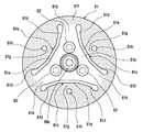
以下、本発明の実施の形態である動力伝達装置について、添付した図面を用いて詳細に説明する。図1は本発明の第1実施形態における動力伝達装置の正面図であり、図2は図1の動力伝達装置の縦断面図、図3は図1・図2に示す動力伝達装置のハブ2の斜視図である。(First embodiment)
Hereinafter, a power transmission device according to an embodiment of the present invention will be described in detail with reference to the accompanying drawings. 1 is a front view of a power transmission device according to a first embodiment of the present invention, FIG. 2 is a longitudinal sectional view of the power transmission device of FIG. 1, and FIG. 3 is a
本動力伝達装置は、車両用空調装置のコンプレッサなど、エンジンやモータなどの駆動源からの回転動力を受けて回転する回転機器7に組み付けられて好適なものである。本動力伝達装置は、駆動源から駆動を得る駆動側回転部材としてのプーリ1と、コンプレッサ7のシャフト(回転軸)3に固定された従動側回転部材としてのハブ2との間で回転動力(回転トルク)を伝達するものである。このプーリ1とハブ2とは、同軸上に設けられている。 This power transmission device is preferably assembled to a
プーリ1は、コンプレッサ7のハウジング4の一端側に設けられた円筒部4aに軸受装置としてのベアリング5を介して回転可能に装着されている。このプーリ1は、好適には熱可塑性の合成樹脂で成型されるが、鉄などの金属材で形成されても良い。プーリ1が樹脂製の場合、通常はプーリ1とベアリング5とはインサート成形により一体化している。 The pulley 1 is rotatably mounted on a
プーリ1の外周面には図示しないベルトが巻き掛けられ、エンジンやモータなどの外部からの動力によって回転する。ベアリング5は、円筒部4aに嵌合しており、円筒部4aの外周面に形成された溝に嵌め込まれた留め輪としてのスナップリング5aによって、軸方向の移動が阻止されている。またハウジング4とシャフト3とは軸封装置としてのシャフトシール6aによって密封されており、冷媒やオイルなどが漏れるのを防止している。 A belt (not shown) is wound around the outer peripheral surface of the pulley 1 and is rotated by external power such as an engine or a motor. The
コンプレッサ7のシャフト3の先端部31はハウジング4から突出していて、その先端部31の外周面にはネジ部が形成されており、円筒状のハブ2が螺合によって先端部31に固定されている。なお、シャフト3へのハブ2の固定は、スプライン係合、ボルトによる取り付けなど、他の固定方法を適宜採用することができる。また、符号8はワッシャである。 The
ハブ2は、インナーハブ21、トルク伝達用弾性部材としてのダンパーゴム22およびアウターハブ23に加えてハブ側係合部24とより構成されている。インナーハブ21は、シャフト3の先端部31に螺合される円筒部21aと、フロント側(図2の左側)に突出し、その外周面がダンパーゴム22に接合される円筒状のフランジ部21cと、円筒部21aとフランジ部21cとをつなぐ円盤状の中間部21bとより成る。 The
円筒部21aの内周面には、ネジ部が形成されている。インナーハブ21は、鉄などの金属材により形成される。アウターハブ23は、円筒状をしていて、インナーハブ21と同様に鉄などの金属材により形成されている。トルク伝達用弾性部材である環状のダンパーゴム22は、EPDM・AEM・塩素化ブチルのゴム材の弾性部材で形成され、インナーハブ21とアウターハブ23間に介在して保持され、インナーハブ21のフランジ部21cの外周面、およびアウターハブ23の内周面に接着の手段によって接合されている。 A screw portion is formed on the inner peripheral surface of the
このダンパーゴム22は、トルク伝達用弾性体として機能するだけでなく、トルクダンパとしても機能する。アウターハブ23のリア側(図2の右側、図3の上側)の内周面23aには第1のハブ側係合部24aが、またその外周面23bには第2のハブ側係合部24bが、アウターハブ23の略全周に渡って設けられている。 The
第1・第2のハブ側係合部24a・24bは、EPDMやAEMのゴム材の弾性材から形成され、その外形形状は、インボリュートスプラインやトロコイドなどの凹凸形状をしている。これら第1・第2のハブ側係合部24a・24bは、アウターハブ23のそれぞれの周面に接着により接合されている。なお、先のダンパーゴム22と両ハブ21・23との接着方法、およびハブ側係合部24とアウターハブ23との接着方法は、本発明の要部であるため、後で詳しく説明する。 The first and second hub
なお、ハブ側係合部24は、アウターハブ23の内周面23aかまたは外周面23bの一方に設けるようにしても良いし、または、図2に示されるように、第1・第2のハブ側係合部24a・24bおよびダンバーゴム22とを一体化して、第1・第2のハブ側係合部24a・24bがアウターハブ23のリア側の部分を包み込むようにしても良い。また、ダンバーゴム22が無く、過大な負荷トルクが生じた際に優先的に破損するトルクリミッタ部を有するハブ2であっても良い。 The hub
一方、プーリ1においても、フロント側の面にハブ側係合部24を受け入れるための環状の凹部11が形成されている。この環状凹部11の内側の面11aと外側の面11bとに、外形形状がインボリュートスプラインやトロコイドなどの凹凸形状をした第1と第2のプーリ側係合部12a・12bが形成されている。 On the other hand, in the pulley 1, an
なお、第1と第2のプーリ側係合部12a・12bも、EPDMやAEMのゴム材の弾性材で形成して、環状凹部11の内側の面11aや外側の面11bに接着するようにしても良いし、環状凹部11の内側の面11aか、外側の面11bかの一方にプーリ側係合部12を形成するようにしても良い。 The first and second pulley
こうして、ハブ側係合部24をプーリ1の環状の凹部11(プーリ側係合部12)に嵌め込むことによって、第1のハブ側係合部24aと第1のプーリ側係合部12aとが噛合し、また第2のハブ側係合部24bと第2のプーリ側係合部12bとが噛合することによって、ハブ2とプーリ1とが連結される。 Thus, by fitting the hub
なお、上述の説明においては、ハブ側係合部24およびアウターハブ23とが、その全周が連続した円環状に形成されるものとしたが、図1や、図3のハブ2の斜視図に示されるように、ハブ側係合部24およびアウターハブ23のリア側部分とが、周方向に適宜の間隔を開けて複数のスリット25が形成されるようにしても良い。 In the above description, the hub-
ハブ側係合部24およびアウターハブ23のリア側部分とを、このように複数分割形状とすることにより、例えば金属製のプーリ1よりも比較的に強度が劣る樹脂などの材料からなるプーリ1において、プーリ1の凹部11の底面に径方向に強度補強部位としてのリブ11cなどが設けられているプーリ構造においても(図1参照)、このリブ11cをスリット25に対応させることによって、プーリ1とハブ2との干渉の心配もなく、安価で小型軽量の動力伝達装置を得るようにしても良い。 By making the hub
次に、本実施形態での特徴と、その効果について述べる。図4は、本発明の一実施形態における弾性部材と金属との接着方法を示す断面模式図である。まず、EPDM(過酸化物加硫系のエチレン・プロピレン・ジエン共重合体の弾性部材)もしくはAEM(過酸化物加硫系のアクリル・エチレン共重合体の弾性部材)と金属との接着方法において、少なくともフェノール樹脂系加硫接着剤Fとシリコン化合物系加硫接着剤Cとを用いて加硫接着している。 Next, features and effects of this embodiment will be described. FIG. 4 is a schematic cross-sectional view showing a method for bonding an elastic member and a metal in one embodiment of the present invention. First, EPDM (peroxide vulcanized ethylene / propylene / diene copolymer elastic member) or AEM (peroxide vulcanized acrylic / ethylene copolymer elastic member) and metal bonding method These are vulcanized and bonded using at least a phenol resin vulcanized adhesive F and a silicon compound vulcanized adhesive C.
フェノール樹脂系加硫接着剤Fの具体例としては、例えばロード社製のケムロック205やケムロック200など、シリコン化合物系加硫接着剤Cの具体例としては、例えばロード社製のケムロック608やAP133などが挙げられる。そして図5は、塩水噴霧時間に対する接着強度変化率を表したグラフである。 Specific examples of the phenol resin-based vulcanized adhesive F include, for example, Chemlock 205 and
これによれば、グラフからも解るように、フェノール樹脂系加硫接着剤Fとシリコン化合物系加硫接着剤Cとの2層構造とすることにより、過酸化物加硫のEPDMやAEMと金属とを強固に接着することができる。また、金属に接着して用いる弾性部材として、ゴム材質の選択範囲を拡げることができる。 According to this, as can be seen from the graph, by using a two-layer structure of phenol resin vulcanized adhesive F and silicon compound vulcanized adhesive C, peroxide vulcanized EPDM, AEM and metal Can be firmly bonded. Moreover, the selection range of a rubber material can be expanded as an elastic member used by adhering to a metal.
また、金属−フェノール樹脂系加硫接着剤F−シリコン化合物系加硫接着剤C−EPDMもしくはAEMの順に積層して接着している。これによれば、シリコン化合物系加硫接着剤Cと金属との間にフェノール樹脂系加硫接着剤Fの層を形成することにより金属との接着部に水を通しにくくすることができ、過酸化物加硫のEPDMやAEMと金属とを強固に接着することができる。 Further, the metal-phenolic resin-based vulcanized adhesive F-silicon compound-based vulcanized adhesive C-EPDM or AEM is laminated and bonded in this order. According to this, by forming a layer of the phenol resin vulcanized adhesive F between the silicon compound vulcanized adhesive C and the metal, it is possible to make it difficult for water to pass through the bonded portion with the metal. Oxide vulcanized EPDM and AEM can be firmly bonded to metal.
また、フェノール樹脂系加硫接着剤Fおよびシリコン化合物系加硫接着剤Cの厚さを、それぞれ3〜15μmとしている。また、金属の表面粗さを、Rz3〜12.5としている。これらによれば、いずれも本領域において良好な接着力を得ることができる。 The thicknesses of the phenol resin vulcanized adhesive F and the silicon compound vulcanized adhesive C are 3 to 15 μm, respectively. Moreover, the surface roughness of the metal is set to Rz3 to 12.5. According to these, all can obtain a good adhesive force in this region.
また、ハブ側係合部24にEPDMもしくはAEMの弾性部材を用いるとともに、金属製のハブ2とハブ側係合部24とを上記した弾性部材と金属との接着方法を用いて接着している。これによれば、耐磨耗性の優れた動力伝達装置とすることができる。また、ダンバーゴム22にもEPDMもしくはAEMを用いるとともに、金属製の両側ハブ21・23とダンバーゴム22とを上記した弾性部材と金属との接着方法を用いて接着している。これによっても、耐久性の優れた動力伝達装置とすることができる。 In addition, an EPDM or AEM elastic member is used for the hub-
なお、ハブ側係合部24にEPDMもしくはAEMを用いた動力伝達装置において、補機の共振とゴムの共振が近い場合にはダンバーゴム22に塩素化ブチルを用いると良く、補機の共振とゴムの共振がやや離れている場合にはダンバーゴム22にAEMを用いると良く、補機の共振とゴムの共振がかなり低い場合にはダンバーゴム22にEPDMを用いると良い。 In the power transmission device using EPDM or AEM for the hub-
(第2実施形態)
図6は、本発明の第2実施形態における電磁クラッチ100を示す縦断面図であり、図7は、図6に示すバネ板部材61の正面図であり、接着範囲をハッチングで示している。本実施形態は、車両空調用冷凍サイクルのコンプレッサ7に装着される電磁クラッチ100に本発明を適用した例を示す。(Second Embodiment)
FIG. 6 is a longitudinal sectional view showing the
電磁クラッチ100は、ステータ20内に収容された電磁コイル30と、図示しない車両エンジンによって回転駆動される駆動側回転部材としてのロータ40と、電磁コイル30の発生する電磁力によってロータ40に吸着されるアーマチュア50と、このアーマチュア50に連結され、アーマチュア50と一体に回転する従動側回転部材としてのハブ6とを備えている。このハブ6は、コンプレッサ7のシャフト3に連結され、コンプレッサ7に回転動力を伝えるものである。 The
ステータ20は、鉄などの磁性体で断面コ字形に形成され、このステータ20内に電磁コイル30が収容されている。そして、電磁コイル30は、エポキシなどの絶縁樹脂部材によってステータ20内に電気絶縁してモールド固定されている。なお、ステータ20は、リング状の支持部材9を介してコンプレッサ7のハウジング4に固定されている。 The
ロータ40は、その外周部に図示しない多段式のVベルトが掛け渡されるプーリ41aを有し、Vベルトを介して伝達されたエンジンの回転動力によって回転する。ロータ40は、鉄などの磁性体で形成されており、ステータ20と微小隙間を介在して収容する断面コ字形に形成されている。また、ロータ40は、その内周にベアリング5を備え、このベアリング5によってロータ40は、コンプレッサハウジング4の円筒ボス部4aの外周面上に回転自在に支持される。 The
アーマチュア50は、ロータ40の摩擦面に所定の微小間隙(例えば0.5mm程度)を隔てて対向配置されるもので、鉄などの磁性体でリング状に形成されている。本例のアーマチュア50は、図示しないが内側リング部と外側リング部との間に磁気遮断用の溝部を形成している。この溝部を円周方向に複数に分割して、溝部相互間のブリッジ部(連結部)により内側リング部と外側リング部とを一体に連結している。 The
次に、ハブ6の詳細について説明すると、鉄系金属にて円筒状に形成されたインナーハブ60を有し、このインナーハブ60の円筒部内周面にはスプライン嵌合部60aが形成され、このスプライン嵌合部60aにてシャフト3と回転方向にて一体に嵌合される。また、インナーハブ60円筒部の軸方向の一端部(図6の左端部)から半径方向の外方へ延びる取り付けフランジ部60bを、円周方向の3箇所に一体形成している。 Next, the details of the
この3箇所の取り付けフランジ部60bには、バネ板部材61の内周部の従動側連結部61a(図7)が3本のリベット62により連結されている。このバネ板部材61は、鉄系の金属バネ材により構成され、その全体形状は図7に示すように円板状に形成されている。 The three
また、インナーハブ60の円筒部の軸方向の一端部(図6の左端部)から半径方向の内方へリング状に突出するリング部60cが形成され、このリング部60cがボルト10によりシャフト3の先端面に締め付け固定される。これにより、ハブ6をシャフト3に一体に連結することができる。 In addition, a
バネ板部材61は、図7に示すように、内周部の従動側連結部61a、より具体的には上記リベット62による連結部と、外周リング部61fとの間に半径方向延びる板バネ部61bが3箇所形成されている。従って、板バネ部61bの長手方向が半径方向に向くようになっている。 As shown in FIG. 7, the
この板バネ部61bの形成のために、板バネ部61bの円周方向の両側を区画する切欠き溝61cが形成してある。ここで、切欠き溝61cは湾曲形状であり、隣接する板バネ部61bの円周方向の片側に位置する溝部61dと、この溝部61d同士をつなぐ中間溝部61eとを有し、中間溝部61eが最も内周側に位置することにより湾曲形状をなしている。 In order to form the
上記した3箇所の板バネ部61bの外周側の先端部は外周リング部61fに一体に連結されている。従って、バネ板部材61は、その内周部の従動側連結部61aから外周リング部61fに至る部分までが1つの円板形状として一体に繋がっている。 The distal end portions on the outer peripheral side of the three
ところで、本実施形態では、切欠き溝61cの中間溝部61eがアーマチュア50の内周面より更に内側へ位置するように切欠き溝61cの湾曲形状を設定している。これにより、3個の板バネ部61b相互の中間部に、外周リング部61fの面積を拡大する幅広部61gを形成することができ、且つ、この幅広部61gの最内周部はアーマチュア50の内周面より内側まで延ばすことができる。 By the way, in this embodiment, the curve shape of the
次に、バネ板部材61とアーマチュア50は略同一の外径となっており、バネ板部材61とアーマチュア50との間には、これらを直接連結する弾性部材63が配置されている。この弾性部材63は、ゴム系弾性材からなるもので、図6に示すように、アーマチュア50のリング形状に対応したリング状の板形状である。この弾性部材63は、所定の成形型内にて加硫接着(焼付接着)方法によってバネ板部材61とアーマチュア50の双方に一体に接着(固着)されている。 Next, the
より具体的に弾性部材63は、アーマチュア50に対しては内側リングおよび外側リングに全面的に接着されるが、バネ板部材61に対しては、切欠き溝61cよりも外周寄りの部分すなわち、図7の細点部に示す如く外周リング部61f・幅広部61gの部分のみに弾性部材63が焼付接着される。 More specifically, the
従って、バネ板部材61のうち、アーマチュア50の内側リングの内周面より外周側に位置する部分であっても、従動側連結部61a・板バネ部61bの部分には弾性部材63を焼付接着しない。これは、板バネ部61bの弾性変形が弾性部材63の接着により阻害されることを防止するためである。 Therefore, even in the portion of the
なお、焼付接着の工程において、従動側連結部61a・板バネ部61bへの接着材の塗布をマスキングするなどの方法を採用することにより、従動側連結部61a・板バネ部61bへの弾性部材63の接着を容易に阻止することができる。 また、弾性部材63に用いるゴム材質としては、車両の使用環境温度の広範な変化(−30°C〜120°C)に対してトルク伝達およびトルク変動吸収(振動減衰)の面で優れた特性を発揮するものが好ましい。 In addition, by adopting a method such as masking the application of the adhesive material to the driven
具体的には、過酸化物加硫系のエチレン・プロピレン・ジエン共重合体の弾性部材(EPDM)もしくは過酸化物加硫系のアクリル・エチレン共重合体の弾性部材(AEM)を用いている。また、その接着にはフェノール樹脂系加硫接着剤とシリコン化合物系加硫接着剤との2層構造(フェノール樹脂系加硫接着剤が金属側)として加硫接着を行っている。 Specifically, a peroxide vulcanized ethylene / propylene / diene copolymer elastic member (EPDM) or a peroxide vulcanized acrylic / ethylene copolymer elastic member (AEM) is used. . Further, for the adhesion, vulcanization adhesion is performed as a two-layer structure of a phenol resin vulcanization adhesive and a silicon compound vulcanization adhesive (the phenol resin vulcanization adhesive is on the metal side).
なお、バネ板部材61の3個の穴61hは、上記加硫接着の工程を実施する際に、図示しないピンを挿入してアーマチュア50に押し当てて、アーマチュア50を型内の所定位置に保持するためのものである。同様に、アーマチュア50の3箇所の穴51は、上記加硫接着の工程を実施する際に、図示しないピンを挿入してバネ板部材61に押し当てて、バネ板部材61を型内の所定位置に保持するためのものである。 The three
また、本実施形態では弾性部材63にアーマチュア50の内周面および外周面をそれぞれ被覆する薄膜状の被覆部63a・63bを一体に設けているので、この薄膜状の被覆部63a・63bに表面処理層と同等の表面保護作用を兼務させることができる。そのため、アーマチュア50への表面処理工程を不要とすることができる。 In the present embodiment, since the
次に、上記構成において本実施形態の作動を説明すると、電磁コイル30の通電停止時(クラッチオフ時)には、バネ板部材61の板バネ部61bのバネ力によってアーマチュア50がロータ40の摩擦面より所定間隔離れた位置に保持されている。このため、図示しない車両エンジンからの回転動力はVベルトを介してロータ40に伝達されるだけで、アーマチュア50およびハブ6へは伝達されない。従って、ロータ40のみがベアリング5上で空転するだけであり、コンプレッサ7は停止している。 Next, the operation of the present embodiment in the above configuration will be described. When the energization of the
一方、電磁コイル30が通電されると、電磁コイル30の発生する電磁力によってアーマチュア50がバネ板部材61の板バネ部61bのバネ力に抗してロータ40に吸引され、アーマチュア50がロータ40に吸着される。すると、ロータ40の回転がアーマチュア50・弾性部材63・バネ板部材61およびインナーハブ60を介してコンプレッサ7のシャフト3に伝達され、コンプレッサ7が作動する。また、電磁コイル30への通電が遮断されると、電磁力の消滅によりアーマチュア50がバネ板部材61の板バネ部61bのバネ力により元の乖離位置に復帰し、コンプレッサ7が停止状態に戻る。 On the other hand, when the
ところで、アーマチュア50とバネ板部材61の外周リング部61fとの間に弾性部材63を介在し、接着しているので、上記のクラッチオン時に、アーマチュア50がロータ40に吸着される過程において、アーマチュア50がロータ40の摩擦面に吸着されるときの衝撃・振動を弾性部材63の振動減衰作用により緩和できる。同様に、コンプレッサ7の駆動トルク変動に起因する捩じれ共振も弾性部材63の振動減衰作用により緩和できる。これらの弾性部材63の振動減衰作用により、電磁クラッチ100およびコンプレッサ7の作動騒音を効果的に低減できる。 Incidentally, since the
しかも、クラッチオフ時のアーマチュア50の軸方向復帰動作はバネ板部材61の板バネ部61bのバネ力により行うことができるから、弾性部材63にアーマチュア50の軸方向復帰動作のためのバネ作用を兼務させる必要がない。そのため、弾性部材63の形状をアーマチュア50とバネ板部材61の外周リング部61fの半径方向に沿った薄い板状の形状にすることができ、弾性部材63の軸方向寸法(板厚)は例えば2mm程度にすることができ、従来の円筒状弾性部材の軸方向寸法(通常、10mm程度)に比して大幅に小さくできる。 In addition, since the return operation of the
さらに、何らかの原因でコンプレッサ7のロック現象が発生した際には、コンプレッサ7のシャフト3に連結されたハブ6およびアーマチュア50が回転不能となり、そのため、ロータ40がアーマチュア50に対して滑りながら回転することになる。その結果、ロータ40とアーマチュア50との間の摩擦面が発熱し、弾性部材63の温度が上昇する。 Further, when the lock phenomenon of the
そして、弾性部材63の材質で決まる溶断温度まで温度が上昇すれば、弾性部材63が溶断して、アーマチュア50とバネ板部材61との連結状態が遮断される。従って、これ以後、ロータ40にアーマチュア50が吸着されたままとなり、ロータ40がアーマチュア50と一体に回転するとともに、アーマチュア50とバネ板部材61との間のトルク伝達が遮断されるので、コンプレッサ7のロック現象による過負荷状態が解除される。よって、この過負荷状態の長時間継続によるベルト切れや異常な温度上昇といった不具合の発生を未然に抑制できる。 When the temperature rises to the fusing temperature determined by the material of the
また、バネ板部材61の内周部の従動側連結部61aと外周リング部61fとの間に、複数の板バネ部61bを半径方向へ延びるように形成している。このため、複数の板バネ部61b相互の中間部に、外周リング部61fの面積を拡大する幅広部61gを形成することができる。 Further, a plurality of
これにより、バネ板部材61と弾性部材63との接着面積を拡大して、この両部材61・63間の接合強度を増加でき、クラッチのねじり耐久性を向上できる。なお、このねじり耐久性は、アーマチュア50とハブ6(バネ板部材61)との間にコンプレッサ最大トルクの印加と解放を所定の時間間隔で繰り返し、弾性部材63が破断してトルク伝達が不能となるまでのコンプレッサ最大トルクの印加回数で評価することができる。 As a result, the bonding area between the
なお、上記実施形態においては、アーマチュア50の内側リング部5と外側リング部との間を、円弧状の複数の磁気遮断溝相互間のブリッジ部(連結部)により一体に連結する構成として、アーマチュア50の全体を一体部品としているが、アーマチュア50の内側リング部と外側リング部とをそれぞれ別体で形成するとともに、内側リング部と外側リング部との間に磁気遮断溝を配置し、内側リング部と外側リング部とを弾性部材63を介してバネ板部材61に一体に接着する構成としても良い。 In the above-described embodiment, the
次に、本実施形態での特徴と、その効果について述べると、弾性部材63に過酸化物加硫系のエチレン・プロピレン・ジエン共重合体の弾性部材(EPDM)もしくは過酸化物加硫系のアクリル・エチレン共重合体の弾性部材(AEM)を用いるとともに、金属製のアーマチュア50およびバネ板部材61と弾性部材63とを、前述した第1実施形態と同様の弾性部材と金属との接着方法を用いて接着している。これによれば、耐久性の優れた動力伝達装置とすることができる。 Next, the characteristics and effects of this embodiment will be described. The
尚、本実施形態における過酸化物加硫系のエチレン・プロピレン・ジエン共重合体の弾性部材(EPDM)および過酸化物加硫系のアクリル・エチレン共重合体の弾性部材(AEM)は、有機過酸化物(例えば、日本油脂のパーヘキサ25Bなど)を用いた非硫黄架橋を施したエチレン・プロピレン・ジエン共重合体の弾性部材(EPDM)およびアクリル・エチレン共重合体の弾性部材(AEM)のことである。また、本明細書においては、「過酸化物加硫系」と「過酸化物架橋系」を同義の語句として用いている。 In this embodiment, the peroxide vulcanized ethylene / propylene / diene copolymer elastic member (EPDM) and the peroxide vulcanized acrylic / ethylene copolymer elastic member (AEM) are organic. Non-sulfur cross-linked ethylene / propylene / diene copolymer elastic member (EPDM) and acrylic / ethylene copolymer elastic member (AEM) using a peroxide (for example, Perhexa 25B of NOF) That is. In the present specification, “peroxide vulcanization system” and “peroxide crosslinking system” are used as synonymous terms.
(その他の実施形態)
上述の実施形態では、本発明の弾性部材と金属との接着方法を動力伝達装置に適用しているが、本発明は上述した実施形態に限定されるものではなく、防振装置の金属部材と防振ゴムとの接着などに適用しても良く、特に高温に晒される部位の接着に適している。また、金属表面への処理として亜リン酸塩処理を用いても良い。また、上述の実施形態では、シリコン化合物系接着剤として、シラン系の接着剤を用いたが、本発明はこれに限定されるものではなく、シリコン系化合物であればどのようなものであっても良い。(Other embodiments)
In the above-described embodiment, the elastic member and metal bonding method of the present invention is applied to the power transmission device, but the present invention is not limited to the above-described embodiment, It may be applied to adhesion with vibration-proof rubber, and is particularly suitable for adhesion to a portion exposed to high temperature. Moreover, you may use a phosphite process as a process to a metal surface. In the above-described embodiment, a silane-based adhesive is used as the silicon compound-based adhesive. However, the present invention is not limited to this, and any silicon-based compound can be used. Also good.
1…プーリ
2…ハブ
3…シャフト(回転軸)
7…コンプレッサ(回転機器)
12…プーリ側係合部
21…インナーハブ
22…ダンバーゴム(トルク伝達用弾性部材)
23…アウターハブ、ハブの外周部
24…ハブ側係合部
30…電磁コイル
50…アーマチュア
60…インナーハブ
61…バネ板部材
63…弾性部材
C…シリコン化合物系加硫接着剤
F…フェノール樹脂系加硫接着剤
AEM…アクリル・エチレン共重合体の弾性部材
EPDM…エチレン・プロピレン・ジエン共重合体の弾性部材1 ...
7 ... Compressor (Rotating equipment)
12 ... Pulley
DESCRIPTION OF
Claims (7)
Translated fromJapanese少なくともフェノール樹脂系加硫接着剤(F)とシリコン化合物系加硫接着剤(C)とを用いて加硫接着していることを特徴とする弾性部材と金属との接着方法。It is a method of bonding a metal vulcanized with a peroxide vulcanized ethylene / propylene / diene copolymer elastic member (EPDM) or a peroxide vulcanized acrylic / ethylene copolymer elastic member (AEM).
A method of adhering an elastic member and a metal, characterized in that at least a phenol resin vulcanized adhesive (F) and a silicon compound vulcanized adhesive (C) are vulcanized and bonded.
駆動源から回転動力を受けて回転するプーリ(1)と、
前記プーリ(1)と同軸状に配置されともに、前記回転機器(7)の回転軸(3)に連結されて前記回転軸(3)と一体に回転するハブ(2)とからなり、
前記ハブ(2)は、前記プーリ(1)のフロント側端面と係合される外周部(23)の内周面側または外周面側、あるいは内外周面側に結合させた弾性部材よりなるハブ側係合部(24)を有し、
前記プーリ(1)は、前記ハブ(2)の前記外周部(23)に対応する前記フロント側端面に形成したプーリ側係合部(12)を有し、
前記ハブ側係合部(24)と前記プーリ側係合部(12)とを係合させることにより、前記ハブ(2)と前記プーリ(1)とのトルク伝達構造を形成している動力伝達装置において、
前記ハブ側係合部(24)に過酸化物加硫系のエチレン・プロピレン・ジエン共重合体の弾性部材(EPDM)もしくは過酸化物加硫系のアクリル・エチレン共重合体の弾性部材(AEM)を用いるとともに、
金属製の前記ハブ(2)と前記ハブ側係合部(24)とを請求項1ないし請求項4のいずれか1項に記載の弾性部材と金属との接着方法を用いて接着したことを特徴とする動力伝達装置。A power transmission device for transmitting the rotational power of the drive source to the rotary device (7) on the passive side;
A pulley (1) that receives rotational power from a drive source and rotates;
A hub (2) that is coaxially arranged with the pulley (1) and is connected to the rotating shaft (3) of the rotating device (7) and rotates integrally with the rotating shaft (3),
The hub (2) is a hub made of an elastic member coupled to the inner peripheral surface side or outer peripheral surface side of the outer peripheral portion (23) engaged with the front side end surface of the pulley (1), or the inner peripheral surface side. Having a side engagement portion (24),
The pulley (1) has a pulley side engaging portion (12) formed on the front side end surface corresponding to the outer peripheral portion (23) of the hub (2),
Power transmission forming a torque transmission structure between the hub (2) and the pulley (1) by engaging the hub side engaging portion (24) and the pulley side engaging portion (12). In the device
A peroxide vulcanized ethylene / propylene / diene copolymer elastic member (EPDM) or a peroxide vulcanized acrylic / ethylene copolymer elastic member (AEM) is formed on the hub side engaging portion (24). )
The metal hub (2) and the hub side engaging portion (24) are bonded together using the elastic member and metal bonding method according to any one of claims 1 to 4. A power transmission device.
駆動源から回転動力を受けて回転するプーリ(1)と、
前記プーリ(1)と同軸状に配置されるともに、前記回転機器(7)の回転軸(3)に連結されて前記回転軸(3)と一体に回転するハブ(2)とからなり、
前記ハブ(2)は、前記回転軸(3)に連結されるインナーハブ(21)と、
前記プーリ(1)のフロント側端面と係合されるアウターハブ(23)と、
前記両側ハブ(21、23)の間に介在して両者と結合されたトルク伝達用弾性部材(22)と、
前記アウターハブ(23)に形成されたハブ側係合部(24)とからなり、
前記プーリ(1)は、前記フロント側端面の前記アウターハブ(23)に対応する位置に形成したプーリ側係合部(12)を有し、
前記ハブ側係合部(24)と前記プーリ側係合部(12)とを係合させることにより、前記ハブ(2)と前記プーリ(1)とのトルク伝達構造を形成している動力伝達装置において、
前記トルク伝達用弾性部材(22)に過酸化物加硫系のエチレン・プロピレン・ジエン共重合体の弾性部材(EPDM)もしくは過酸化物加硫系のアクリル・エチレン共重合体の弾性部材(AEM)を用いるとともに、
金属製の前記両側ハブ(21、23)と前記トルク伝達用弾性部材(22)とを請求項1ないし請求項4のいずれか1項に記載の弾性部材と金属との接着方法を用いて接着したことを特徴とする動力伝達装置。A power transmission device for transmitting the rotational power of the drive source to the rotary device (7) on the passive side;
A pulley (1) that receives rotational power from a drive source and rotates;
The hub (2) is arranged coaxially with the pulley (1) and is connected to the rotating shaft (3) of the rotating device (7) and rotates integrally with the rotating shaft (3).
The hub (2) includes an inner hub (21) connected to the rotating shaft (3),
An outer hub (23) engaged with a front side end face of the pulley (1);
A torque transmitting elastic member (22) interposed between the both hubs (21, 23) and coupled to both;
A hub side engaging portion (24) formed on the outer hub (23),
The pulley (1) has a pulley side engaging portion (12) formed at a position corresponding to the outer hub (23) of the front side end surface,
Power transmission forming a torque transmission structure between the hub (2) and the pulley (1) by engaging the hub side engaging portion (24) and the pulley side engaging portion (12). In the device
The torque transmitting elastic member (22) is a peroxide vulcanized ethylene / propylene / diene copolymer elastic member (EPDM) or a peroxide vulcanized acrylic / ethylene copolymer elastic member (AEM). )
The metal hubs (21, 23) and the torque transmitting elastic member (22) are bonded using the elastic member and metal bonding method according to any one of claims 1 to 4. A power transmission device characterized by that.
駆動源から回転動力を受けて回転するプーリ(1)と、
前記プーリ(1)と同軸状に配置されるともに、前記回転機器(7)の回転軸(3)に連結されて前記回転軸(3)と一体に回転するハブ(2)とからなり、
前記プーリ(1)は、通電によって電磁力を発生する電磁コイル(30)を有し、
前記ハブ(2)は、前記回転軸(3)に連結されるインナーハブ(60)と、
前記電磁コイル(30)の発生する電磁力により前記プーリ(1)吸着されて前記プーリ(1)の回転動力を受けるアーマチュア(50)と、
前記インナーハブ(60)と連結されて前記アーマチュア(5)を前記プーリ(1)から乖離する方向のバネ力を発生する円板状のバネ板部材(61)とからなり、
前記アーマチュア(50)と前記バネ板部材(61)との間を弾性部材(63)により直接連結した動力伝達装置において、
前記弾性部材(63)に過酸化物加硫系のエチレン・プロピレン・ジエン共重合体の弾性部材(EPDM)もしくは過酸化物加硫系のアクリル・エチレン共重合体の弾性部材(AEM)を用いるとともに、
金属製の前記アーマチュア(50)および前記バネ板部材(61)と前記弾性部材(63)とを請求項1ないし請求項4のいずれか1項に記載の弾性部材と金属との接着方法を用いて接着したことを特徴とする動力伝達装置。A power transmission device for transmitting the rotational power of the drive source to the rotary device (7) on the passive side;
A pulley (1) that receives rotational power from a drive source and rotates;
The hub (2) is arranged coaxially with the pulley (1) and is connected to the rotating shaft (3) of the rotating device (7) and rotates integrally with the rotating shaft (3).
The pulley (1) has an electromagnetic coil (30) that generates electromagnetic force when energized,
The hub (2) includes an inner hub (60) connected to the rotating shaft (3),
An armature (50) that is attracted to the pulley (1) by electromagnetic force generated by the electromagnetic coil (30) and receives rotational power of the pulley (1);
A disc-shaped spring plate member (61) that is connected to the inner hub (60) and generates a spring force in a direction of separating the armature (5) from the pulley (1);
In the power transmission device in which the armature (50) and the spring plate member (61) are directly connected by an elastic member (63),
A peroxide vulcanized ethylene / propylene / diene copolymer elastic member (EPDM) or a peroxide vulcanized acrylic / ethylene copolymer elastic member (AEM) is used as the elastic member (63). With
The method for bonding an elastic member and a metal according to any one of claims 1 to 4, wherein the metal armature (50), the spring plate member (61), and the elastic member (63) are used. A power transmission device characterized by being bonded together.
Priority Applications (3)
| Application Number | Priority Date | Filing Date | Title |
|---|---|---|---|
| JP2005084692AJP2006265357A (en) | 2005-03-23 | 2005-03-23 | Method for adhering elastic member with metal and power transmission device |
| DE102006012954ADE102006012954A1 (en) | 2005-03-23 | 2006-03-21 | Adhesion method for belt transmssion pulleys uses ethylene-propylene dien copolymer vulcanisable with peroxide |
| US11/384,298US20060245936A1 (en) | 2005-03-23 | 2006-03-21 | Bonding method for elastic member and metal, and power transmission device |
Applications Claiming Priority (1)
| Application Number | Priority Date | Filing Date | Title |
|---|---|---|---|
| JP2005084692AJP2006265357A (en) | 2005-03-23 | 2005-03-23 | Method for adhering elastic member with metal and power transmission device |
Publications (1)
| Publication Number | Publication Date |
|---|---|
| JP2006265357Atrue JP2006265357A (en) | 2006-10-05 |
Family
ID=36999127
Family Applications (1)
| Application Number | Title | Priority Date | Filing Date |
|---|---|---|---|
| JP2005084692APendingJP2006265357A (en) | 2005-03-23 | 2005-03-23 | Method for adhering elastic member with metal and power transmission device |
Country Status (3)
| Country | Link |
|---|---|
| US (1) | US20060245936A1 (en) |
| JP (1) | JP2006265357A (en) |
| DE (1) | DE102006012954A1 (en) |
Cited By (1)
| Publication number | Priority date | Publication date | Assignee | Title |
|---|---|---|---|---|
| JP2007309461A (en)* | 2006-05-19 | 2007-11-29 | Denso Corp | Power transmission device |
Families Citing this family (8)
| Publication number | Priority date | Publication date | Assignee | Title |
|---|---|---|---|---|
| WO2006085651A1 (en)* | 2005-02-14 | 2006-08-17 | Nsk Ltd. | Hub unit bearing |
| EP1939494A3 (en)* | 2006-12-27 | 2011-03-16 | LuK Lamellen und Kupplungsbau Beteiligungs KG | Drive wheel |
| US9249283B2 (en) | 2009-04-29 | 2016-02-02 | Tundra Composites, LLC | Reduced density glass bubble polymer composite |
| DE102010063238A1 (en)* | 2010-12-16 | 2012-06-21 | Robert Bosch Gmbh | Load torque lock for a transmission drive unit and aggregate with a load torque lock |
| DE102011003757A1 (en)* | 2011-02-08 | 2012-08-09 | Gkn Stromag Aktiengesellschaft | Elastic shaft coupling and elastomer segment |
| FR2993618B1 (en)* | 2012-07-23 | 2014-08-22 | Ntn Snr Roulements | DRIVE MECHANISM FOR ROTATING A ROTATING SHAFT BY MEANS OF A MOTOR MEMBER |
| US10005935B2 (en) | 2015-05-01 | 2018-06-26 | Lord Corporation | Adhesive for rubber bonding |
| RU2708322C1 (en)* | 2015-12-18 | 2019-12-05 | Сандвик Интеллекчуал Проперти Аб | Torque-response pulley for inertial cone crusher |
Citations (7)
| Publication number | Priority date | Publication date | Assignee | Title |
|---|---|---|---|---|
| JPS56112938A (en)* | 1980-02-13 | 1981-09-05 | Showa Denko Kk | Adhesion of chlorinated polyethylene composition to metal surface |
| JPS61202822A (en)* | 1985-03-05 | 1986-09-08 | Toyoda Gosei Co Ltd | Manufacture of vibration insulation rubber provided with metallic housing |
| JPS63238183A (en)* | 1987-03-26 | 1988-10-04 | Toyoda Gosei Co Ltd | Primer for metal |
| JPH01123880A (en)* | 1987-11-10 | 1989-05-16 | Nok Corp | Primer composition for vulcanization bonding and bonding using the same |
| JPH0411684A (en)* | 1990-04-27 | 1992-01-16 | Uchiyama Mfg Corp | Adhesive composition |
| JPH10219001A (en)* | 1997-02-10 | 1998-08-18 | Aisin Seiki Co Ltd | Rubber bonding method |
| JP2002364667A (en)* | 2001-06-06 | 2002-12-18 | Zexel Valeo Climate Control Corp | Power transmission device for compressor |
Family Cites Families (5)
| Publication number | Priority date | Publication date | Assignee | Title |
|---|---|---|---|---|
| US2957794A (en)* | 1955-11-30 | 1960-10-25 | William B Shetterly | Bonding silicone rubber to metal |
| US5496884A (en)* | 1993-11-12 | 1996-03-05 | Lord Corporation | Aqueous adhesive for bonding elastomers |
| US20030066603A1 (en)* | 2001-08-20 | 2003-04-10 | Lord Corporation | Adhesive composition for bonding an elastomer to a substrate and a method for the bonding thereof |
| US20040033374A1 (en)* | 2002-08-16 | 2004-02-19 | Mowrey Douglas H. | Phenolic adhesives for bonding peroxide-cured elastomers |
| US7993228B2 (en)* | 2004-10-19 | 2011-08-09 | Denso Corporation | Power transmission device |
- 2005
- 2005-03-23JPJP2005084692Apatent/JP2006265357A/enactivePending
- 2006
- 2006-03-21DEDE102006012954Apatent/DE102006012954A1/ennot_activeWithdrawn
- 2006-03-21USUS11/384,298patent/US20060245936A1/ennot_activeAbandoned
Patent Citations (7)
| Publication number | Priority date | Publication date | Assignee | Title |
|---|---|---|---|---|
| JPS56112938A (en)* | 1980-02-13 | 1981-09-05 | Showa Denko Kk | Adhesion of chlorinated polyethylene composition to metal surface |
| JPS61202822A (en)* | 1985-03-05 | 1986-09-08 | Toyoda Gosei Co Ltd | Manufacture of vibration insulation rubber provided with metallic housing |
| JPS63238183A (en)* | 1987-03-26 | 1988-10-04 | Toyoda Gosei Co Ltd | Primer for metal |
| JPH01123880A (en)* | 1987-11-10 | 1989-05-16 | Nok Corp | Primer composition for vulcanization bonding and bonding using the same |
| JPH0411684A (en)* | 1990-04-27 | 1992-01-16 | Uchiyama Mfg Corp | Adhesive composition |
| JPH10219001A (en)* | 1997-02-10 | 1998-08-18 | Aisin Seiki Co Ltd | Rubber bonding method |
| JP2002364667A (en)* | 2001-06-06 | 2002-12-18 | Zexel Valeo Climate Control Corp | Power transmission device for compressor |
Cited By (1)
| Publication number | Priority date | Publication date | Assignee | Title |
|---|---|---|---|---|
| JP2007309461A (en)* | 2006-05-19 | 2007-11-29 | Denso Corp | Power transmission device |
Also Published As
| Publication number | Publication date |
|---|---|
| DE102006012954A1 (en) | 2006-10-05 |
| US20060245936A1 (en) | 2006-11-02 |
Similar Documents
| Publication | Publication Date | Title |
|---|---|---|
| JP4174896B2 (en) | Electromagnetic clutch | |
| US20060245936A1 (en) | Bonding method for elastic member and metal, and power transmission device | |
| KR101559446B1 (en) | Disk-Hub assembly for electromagnetic clutch | |
| KR100560612B1 (en) | Electromagnetic clutch | |
| JP4081473B2 (en) | Device for transmitting engine torque to the compressor | |
| KR101765644B1 (en) | Motor coupling structure of engine clutch for hybrid transmission | |
| JP2011027122A (en) | Torque limiter device | |
| KR101061277B1 (en) | Couplings for Electronic Clutch | |
| US7213695B2 (en) | Electromagnetic clutch | |
| JP4556304B2 (en) | Electromagnetic clutch | |
| JP4639993B2 (en) | Electromagnetic clutch | |
| JP5800132B2 (en) | Torque fluctuation absorbing damper | |
| JP4561595B2 (en) | Power transmission device | |
| JP2002276777A (en) | Power transmitting device | |
| KR101090008B1 (en) | Clutch disc assembly | |
| JP4353102B2 (en) | Power transmission device | |
| KR102168451B1 (en) | Electromagnetic clutch for compressor | |
| JP4325567B2 (en) | Power transmission device | |
| KR100561938B1 (en) | Disk & Hub Assembly for Electronic Clutch_ | |
| KR100880896B1 (en) | Disk and Hub Assemblies for Electronic Clutch | |
| JP2006312971A (en) | Electromagnetic clutch | |
| JP2008249023A (en) | Power transmission device | |
| JP4196682B2 (en) | Torque transmission device | |
| JPH11153154A (en) | Coupling | |
| JP2002021875A (en) | Electromagnetic clutch |
Legal Events
| Date | Code | Title | Description |
|---|---|---|---|
| A621 | Written request for application examination | Free format text:JAPANESE INTERMEDIATE CODE: A621 Effective date:20070425 | |
| A977 | Report on retrieval | Free format text:JAPANESE INTERMEDIATE CODE: A971007 Effective date:20091120 | |
| A131 | Notification of reasons for refusal | Free format text:JAPANESE INTERMEDIATE CODE: A131 Effective date:20091201 | |
| A02 | Decision of refusal | Free format text:JAPANESE INTERMEDIATE CODE: A02 Effective date:20100330 |