JP2006262413A - Radio relay apparatus and transmitter thereof - Google Patents
Radio relay apparatus and transmitter thereofDownload PDFInfo
- Publication number
- JP2006262413A JP2006262413AJP2005080622AJP2005080622AJP2006262413AJP 2006262413 AJP2006262413 AJP 2006262413AJP 2005080622 AJP2005080622 AJP 2005080622AJP 2005080622 AJP2005080622 AJP 2005080622AJP 2006262413 AJP2006262413 AJP 2006262413A
- Authority
- JP
- Japan
- Prior art keywords
- power
- signal
- main signal
- relay
- transmission device
- Prior art date
- Legal status (The legal status is an assumption and is not a legal conclusion. Google has not performed a legal analysis and makes no representation as to the accuracy of the status listed.)
- Pending
Links
Images


Landscapes
- Radio Relay Systems (AREA)
- Mobile Radio Communication Systems (AREA)
Abstract
Translated fromJapaneseDescription
Translated fromJapanese本発明は、例えば移動通信用基地局と移動通信端末の間等で信号の中継を行う無線中継装置及びその送信装置に関する。なお、本願中の説明では、本発明をCDMA(Code Division Multiple Access)方式に適用する場合を念頭において説明するが、本発明をCDMA方式以外に適用しても構わない。 The present invention relates to a radio relay apparatus that relays a signal between a mobile communication base station and a mobile communication terminal, for example, and a transmission apparatus thereof. In the description in the present application, the case where the present invention is applied to a CDMA (Code Division Multiple Access) system will be described in mind, but the present invention may be applied to a system other than the CDMA system.
図4に一般的なCDMA方式のセル半径を説明する図を示す。例えばワイドバンドCDMA方式においては、基地局100から各ユーザの携帯端末102へ向けて共通パイロットチャネル(CPICH)というコードドメイン電力が一定の情報を送信することで、各携帯端末102に共通の情報を与えている。基地局100が送信するRF信号のトータル電力(全体電力)は、図5に示すように、各携帯端末102へ送信するユーザ情報チャネル(DPDCH)等を含めたすべてのコードドメイン電力の合計で決定されるため、基地局100から過剰な電力を送信することなく回線容量を増大させることができる。基地局100がカバーするセル半径rは共通パイロットチャネルが届く範囲104で規定されるが、共通パイロットチャネルのコードドメイン電力は一定であるため、セル半径rはほぼ一定である。セル半径rは、人口過密地域では小さく、過疎地域では大きく設定することで、回線容量と設備設置コストの最適化を図っている。ただし、例えば途中に山やビル等が存在する場合には、セル半径rより小さいエリアでも基地局100がカバーすることが困難なエリアが存在する。その場合は、基地局100から無線中継装置を介して各携帯端末102へ向けてRF信号を送信することが行われる。 FIG. 4 is a diagram for explaining a cell radius of a general CDMA system. For example, in wideband CDMA, information common to each
図6に周波数変換型の無線中継装置を用いた場合のセル半径を説明する図を示す。基地局100からの信号は、中継装置106により無線送信され、無線中継区間110を経て中継装置108により受信される。中継装置108は、受信したRF信号を各携帯端末102へ向けて送信する。中継装置106,108による無線中継後のセル半径rは、無線中継後における共通パイロットチャネルのコードドメイン電力により決定される。ただし、無線中継区間110にて発生したフェージングや降雨等によるRF信号の減衰に対して、中継装置108がRF信号のトータル電力を一定となるように制御してしまうと、図7に示すように、ユーザ情報チャネル(DPDCH)数の変動等により共通パイロットチャネルのコードドメイン電力が変化してしまうことになる。すなわち、セル半径rが変化してしまうことになる。セル半径rの変化は無線中継を行わない場合には発生しなかった問題点であり、回線容量の減少を招いたり、セルの端の方にいるユーザが通話しているときにセル内のユーザ数(携帯端末数)が増えると、通話が途絶えてしまう可能性もある。そこで、従来の無線中継装置では、中継装置108は、無線中継区間110にて発生したフェージングや降雨等によるRF信号の減衰に対して、中継装置106により注入されたパイロット信号の電力が一定となるように制御している。 FIG. 6 illustrates a cell radius when a frequency conversion type radio relay apparatus is used. A signal from the
図8に関連技術に係る無線中継装置の概略構成を示す。図8において、送信装置10は中継装置106内に設けられており、受信装置12は中継装置108内に設けられている。 FIG. 8 shows a schematic configuration of a wireless relay apparatus according to related technology. In FIG. 8, the
送信装置10の入力端子14には、共通パイロットチャネル及びユーザ情報チャネル等を有する信号(以下主信号とする)が基地局100から入力される。ここで、主信号におけるユーザ情報チャネル数は変動するため、図9(A)に示すように、入力端子14に入力される主信号の電力も変動する。増幅器16は、入力端子14に入力された主信号を所定の固定利得で増幅して電力合成器22へ出力する。 A signal having a common pilot channel, a user information channel, and the like (hereinafter referred to as a main signal) is input from the
パイロット信号発生器18は、パイロット信号(CW−Pilot)を増幅器20へ出力する。増幅器20は、パイロット信号発生器18からのパイロット信号を所定の固定利得で増幅して電力合成器22へ出力する。電力合成器22は、増幅器16からの主信号に増幅器20からのパイロット信号を重畳した中継用信号をミキサ26へ出力する。ここで、主信号に注入されるパイロット信号の電力は、主信号の電力に比べて十分小さい一定レベルに設定されており、図9(B)に示すように、主信号の電力の変動に対して主信号とパイロット信号の電力比も変動する。 The
局部発振信号発生器24は、局部発振信号をミキサ26へ出力する。ミキサ26は、局部発振信号発生器24からの局部発振信号を用いて、電力合成器22からの中継用信号を周波数変換する。ミキサ26により周波数変換された後の中継用信号は、アンテナ(図示せず)から送信され、無線中継区間110を経て受信装置12のアンテナ(図示せず)により受信される。ここで、無線中継区間110においては、図9(C)に示すように、フェージングや降雨等による中継用信号のトータル電力の減衰が発生し、さらに、中継用信号の減衰レベルが変動する。ただし、無線中継区間110における減衰レベルの変動に対しては、主信号とパイロット信号の電力比はほぼ一定に保たれる。 The local
局部発振信号発生器28は、局部発振信号をミキサ30へ出力する。ここで、局部発振信号発生器24と局部発振信号発生器28とで、出力する局部発振信号の周波数が等しく設定されている。ミキサ30は、局部発振信号発生器28からの局部発振信号を用いて、受信した中継用信号を周波数変換することで、中継用信号の周波数帯域を送信装置10のミキサ26による周波数変換前の帯域に戻す。 The local
可変利得増幅器32は、ミキサ26からの中継用信号を増幅して電力分配器34へ出力する。電力分配器34は、可変利得増幅器32からの中継用信号を増幅器36へ供給するとともに、可変利得増幅器32からの中継用信号の一部をパイロット信号抽出部38へ供給する。増幅器36は、電力分配器34からの中継用信号を所定の固定利得で増幅して出力端子40へ出力する。 The
パイロット信号抽出部38は、電力分配器34からの中継用信号からパイロット信号を抽出してパイロット信号の電力を検出する。そして、パイロット信号抽出部38は、図9(D)に示すように、検出したパイロット信号の電力を一定レベルに保つよう可変利得増幅器32の利得を制御する。ここでの一定レベルは、送信装置10の電力合成器22にて主信号に注入されるパイロット信号の電力に基づき設定される。この利得制御によって、図9(E)に示すように、出力端子40から出力される中継用信号(主信号)の電力を、送信装置10の入力端子14に入力された主信号の電力に一致させるように制御する。出力端子40から出力された中継用信号は、各携帯端末102へ向けて送信される。 The pilot
以上説明したように、図8に示す無線中継装置においては、送信装置10は、電力復元用の情報としてパイロット信号を主信号に注入した中継用信号を送信し、受信装置12は、受信した中継用信号から検出したパイロット信号の電力を一定レベルに保つように制御することで、送信装置10の入力端子14に入力された主信号の電力を復元している。これによって、各携帯端末102へ向けて送信される共通パイロットチャネルのコードドメイン電力、すなわちセル半径rをほぼ一定に保っている。 As described above, in the radio relay apparatus shown in FIG. 8, the
図8に示す無線中継装置においては、送信装置10が送信する中継用信号の電力は入力端子14に入力された主信号の電力の変動とともに変動するため、送信装置10は中継用信号を常に最大電力で送信することができない。そのため、中継用信号の送信電力が低下した場合を考慮して、無線中継区間110の距離を設定する必要がある。したがって、無線中継区間110の距離を長く設定することが困難であり、中継装置106,108の設置箇所に制約が生じることになる。 In the radio relay apparatus shown in FIG. 8, the power of the relay signal transmitted by the
本発明は、無線中継区間の距離を延ばすことができ、中継装置の設置箇所の自由度を高めることができる無線中継装置及びその送信装置を提供することを目的とする。 An object of the present invention is to provide a radio relay apparatus and a transmission apparatus thereof that can extend the distance of the radio relay section and can increase the degree of freedom of the installation location of the relay apparatus.
本発明に係る無線中継装置及びその送信装置は、上述の目的を達成するために以下の手段を採った。 The wireless relay device and the transmission device thereof according to the present invention employ the following means in order to achieve the above-described object.
本発明に係る無線中継装置は、電力が変動する主信号が入力され、主信号に電力復元用情報を重畳した中継用信号を送信する送信装置と、送信装置から送信された中継用信号を受信し、中継用信号から検出した電力復元用情報に基づいて、出力する主信号の電力を送信装置に入力された主信号の電力に一致させるように制御する受信装置と、を備え、送信装置に入力された主信号の電力を受信装置にて復元する無線中継装置であって、送信装置は、主信号の電力を一定レベルに保つように制御する利得制御部と、利得制御部により電力が制御された後の主信号に電力復元用情報を重畳する重畳部と、送信装置に入力された主信号の検出電力または推定電力に応じて、主信号に重畳する電力復元用情報を変更する電力復元用情報制御部と、を有することを要旨とする。 The radio relay apparatus according to the present invention receives a main signal whose power varies and receives a relay signal transmitted from the transmission apparatus and a transmission apparatus that transmits a relay signal in which power restoration information is superimposed on the main signal. And a receiving device that controls the power of the main signal to be output to match the power of the main signal input to the transmitting device based on the power restoration information detected from the relay signal. A wireless relay device that restores the power of the input main signal at the receiving device, and the transmitting device controls the power by a gain control unit that controls the power of the main signal to be maintained at a constant level, and the gain control unit. A power superimposing unit that superimposes the power restoration information on the main signal after being changed, and power restoration that changes the power restoration information superimposed on the main signal according to the detected power or the estimated power of the main signal input to the transmission device Information control unit The gist of the Rukoto.
本発明の一態様では、重畳部は、利得制御部により電力が制御された後の主信号にパイロット信号を前記電力復元用情報として重畳し、電力復元用情報制御部は、送信装置に入力された主信号の検出電力または推定電力に応じて、主信号に重畳するパイロット信号の電力を変更することが好適である。 In one aspect of the present invention, the superimposing unit superimposes a pilot signal as the power recovery information on the main signal whose power is controlled by the gain control unit, and the power recovery information control unit is input to the transmission device. It is preferable to change the power of the pilot signal superimposed on the main signal according to the detected power or estimated power of the main signal.
また、本発明に係る無線中継装置は、電力が変動する主信号が入力され、主信号に電力復元用情報を重畳した中継用信号を送信する送信装置と、送信装置から送信された中継用信号を受信し、中継用信号から検出した電力復元用情報に基づいて、出力する主信号の電力を送信装置に入力された主信号の電力に一致させるように制御する受信装置と、を備え、送信装置に入力された主信号の電力を受信装置にて復元する無線中継装置であって、送信装置は、主信号に電力復元用情報が重畳された中継用信号の全体電力を一定レベルに保つように制御する利得制御部を有し、利得制御部により全体電力が制御された後の中継用信号を送信することを要旨とする。 In addition, the radio relay apparatus according to the present invention receives a main signal whose power fluctuates, transmits a relay signal in which power restoration information is superimposed on the main signal, and a relay signal transmitted from the transmission apparatus And a receiving device that controls the power of the main signal to be output to coincide with the power of the main signal input to the transmitting device based on the power restoration information detected from the relay signal. A radio relay apparatus that restores the power of a main signal input to the apparatus at a receiving apparatus, and the transmission apparatus maintains the overall power of the relay signal in which the power restoration information is superimposed on the main signal at a constant level. The gist is to transmit a relay signal after the overall power is controlled by the gain control unit.
また、本発明に係る無線中継装置の送信装置は、電力が変動する主信号が入力され、主信号に電力復元用情報を重畳した中継用信号を送信する無線中継装置の送信装置であって、送信装置から送信された中継用信号を受信し、中継用信号から検出した電力復元用情報に基づいて、出力する主信号の電力を送信装置に入力された主信号の電力に一致させるように制御することで、送信装置に入力された主信号の電力を復元する受信装置を備えた無線中継装置にて用いられる送信装置において、主信号の電力を一定レベルに保つように制御する利得制御部と、利得制御部により電力が制御された後の主信号に電力復元用情報を重畳する重畳部と、送信装置に入力された主信号の検出電力または推定電力に応じて、主信号に重畳する電力復元用情報を変更する電力復元用情報制御部と、を有することを要旨とする。 Further, the transmission device of the wireless relay device according to the present invention is a transmission device of a wireless relay device that receives a main signal whose power fluctuates and transmits a relay signal in which power restoration information is superimposed on the main signal, Control to match the power of the main signal output to the power of the main signal input to the transmission device based on the power restoration information detected from the relay signal received from the relay signal transmitted from the transmission device A gain control unit for controlling the power of the main signal to be maintained at a constant level in the transmission device used in the wireless relay device including the reception device that restores the power of the main signal input to the transmission device; , A superimposing unit that superimposes power restoration information on the main signal whose power is controlled by the gain control unit, and a power that is superimposed on the main signal according to the detected power or the estimated power of the main signal input to the transmission device Restoration information And summarized in that with a power restoration information control unit for changing.
また、本発明に係る無線中継装置の送信装置は、電力が変動する主信号が入力され、主信号に電力復元用情報を重畳した中継用信号を送信する無線中継装置の送信装置であって、送信装置から送信された中継用信号を受信し、中継用信号から検出した電力復元用情報に基づいて、出力する主信号の電力を送信装置に入力された主信号の電力に一致させるように制御することで、送信装置に入力された主信号の電力を復元する受信装置を備えた無線中継装置にて用いられる送信装置において、主信号に電力復元用情報が重畳された中継用信号の全体電力を一定レベルに保つように制御する利得制御部を有し、利得制御部により全体電力が制御された後の中継用信号を送信することを要旨とする。 Further, the transmission device of the wireless relay device according to the present invention is a transmission device of a wireless relay device that receives a main signal whose power fluctuates and transmits a relay signal in which power restoration information is superimposed on the main signal, Control to match the power of the main signal output to the power of the main signal input to the transmission device based on the power restoration information detected from the relay signal received from the relay signal transmitted from the transmission device Thus, in the transmission apparatus used in the radio relay apparatus including the reception apparatus that restores the power of the main signal input to the transmission apparatus, the overall power of the relay signal in which the power restoration information is superimposed on the main signal The gist of the present invention is to have a gain control unit that controls the power to be maintained at a constant level, and to transmit the relay signal after the overall power is controlled by the gain control unit.
本発明によれば、送信装置に入力される主信号の電力が変動しても、送信装置が送信する中継用信号の電力を略一定にすることができ、中継用信号の送信電力を常に略最大にすることができる。その結果、無線中継区間の距離を延ばすことができ、中継装置の設置箇所の自由度を高めることができる。 According to the present invention, even if the power of the main signal input to the transmission device fluctuates, the power of the relay signal transmitted by the transmission device can be made substantially constant, and the transmission power of the relay signal is always kept substantially constant. Can be maximized. As a result, the distance of the wireless relay section can be extended, and the degree of freedom of the installation location of the relay device can be increased.
以下、本発明を実施するための形態(以下実施形態という)を図面に従って説明する。ただし、図4〜9に示した関連技術と同様の構成または対応する構成には同一の符号を付し、重複する説明を省略する。 DESCRIPTION OF EMBODIMENTS Hereinafter, embodiments for carrying out the present invention (hereinafter referred to as embodiments) will be described with reference to the drawings. However, the same code | symbol is attached | subjected to the structure similar to the related technique shown to FIGS. 4-9, or a corresponding structure, and the overlapping description is abbreviate | omitted.
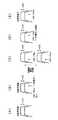
図1は、本発明の実施形態に係る無線中継装置の概略構成を示す図である。本実施形態に係る無線中継装置においては、以下に説明する自動利得制御回路(AGC回路)15、パイロット電力制御部17、及び可変利得増幅器19が送信装置10内に設けられており、以下に説明する自動利得制御回路(AGC回路)31及び可変利得増幅器35が受信装置12内に設けられている。なお、本実施形態に係る無線中継装置も、図8に示した無線中継装置と同様に、周波数変換型の無線中継装置であり、CDMA方式において各携帯端末102へ向けて送信される共通パイロットチャネルのコードドメイン電力、すなわちセル半径rを一定に保つ目的で用いることができる。 FIG. 1 is a diagram illustrating a schematic configuration of a wireless relay device according to an embodiment of the present invention. In the radio relay apparatus according to the present embodiment, an automatic gain control circuit (AGC circuit) 15, a pilot
まず送信装置10側の構成について説明する。自動利得制御回路15は、入力端子14に入力された主信号の電力を一定レベルに保つように制御して電力合成器22へ出力する。可変利得増幅器19は、パイロット信号発生器18からのパイロット信号(CW−Pilot)を増幅して電力合成器22へ出力する。電力合成器22は、自動利得制御回路15により電力が制御された後の主信号に可変利得増幅器19からのパイロット信号を重畳した中継用信号をミキサ26へ出力する。 First, the configuration on the
パイロット電力制御部17は、可変利得増幅器19の利得を例えばディジタル信号処理により制御することで、電力合成器22にて主信号に注入されるパイロット信号の電力を制御する。ここでのパイロット電力制御部17は、送信装置10の入力端子14に入力された主信号の検出電力または推定電力に応じて、可変利得増幅器19の利得を変更することで、主信号に注入するパイロット信号の電力を変更する。例えば自動利得制御回路15がその入力における主信号の検出電力に基づいて利得制御信号を生成することで主信号の電力を制御する場合には、パイロット電力制御部17は、自動利得制御回路15の入力における主信号の検出電力に応じて可変利得増幅器19の利得を変更する。また、自動利得制御回路15がその出力における主信号の検出電力に基づいて利得制御信号を生成することで主信号の電力を制御する場合には、パイロット電力制御部17は、この利得制御信号から入力端子14に入力された主信号の電力を推定し、この推定電力に応じて可変利得増幅器19の利得を変更する。 The pilot
本実施形態では、入力端子14に入力される主信号の電力が図2(A)に示すように変動しても、自動利得制御回路15の利得制御によって、自動利得制御回路15から出力される主信号の電力が一定レベルに保たれる。したがって、図2(B)に示すように、送信装置10が送信する中継用信号の電力を略一定レベルに保つことができる。そして、パイロット電力制御部17による可変利得増幅器19の利得制御によって、図2(B)に示すように、入力端子14に入力される主信号の電力の変動に対して、電力合成器22からの中継用信号における主信号とパイロット信号の電力比も変動する。 In the present embodiment, even if the power of the main signal input to the
次に、受信装置12側の構成について説明する。自動利得制御回路31は、ミキサ26からの中継用信号のトータル電力(全体電力)を一定レベルに保つように制御して電力分配器34へ出力する。可変利得増幅器35は、電力分配器34からの中継用信号、すなわち自動利得制御回路31によりトータル電力が制御された後の中継用信号を増幅して出力端子40へ出力する。 Next, the configuration on the receiving
パイロット信号抽出部38は、電力分配器34からの中継用信号、すなわち自動利得制御回路31によりトータル電力が制御された後の中継用信号からパイロット信号を抽出してパイロット信号の電力を検出する。そして、パイロット信号抽出部38は、検出したパイロット信号の電力に基づいて、出力端子40から出力する中継用信号(主信号が主として含まれる)の電力を送信装置10の入力端子14に入力された主信号の電力に一致させるように、可変利得増幅器35の利得を例えばディジタル信号処理により制御する。 The pilot
本実施形態では、図2(C)に示すように、無線中継区間110にてフェージングや降雨等による中継用信号のトータル電力の減衰が発生し、さらに、中継用信号の減衰レベルが変動する。ただし、無線中継区間110における減衰レベルの変動に対しては、主信号とパイロット信号の電力比はほぼ一定に保たれる。そして、自動利得制御回路31の利得制御によって、自動利得制御回路31から出力される中継用信号のトータル電力は、図2(D)に示すように、無線中継区間110における中継用信号の減衰レベルが変動しても一定レベルに保たれる。ここでの自動利得制御回路31による中継用信号の電力制御については、全体電力を制御するだけでよいので、電力制御の応答性を高めることができる。そのため、無線中継区間110における減衰レベルが高速に変動しても、中継用信号に歪みが発生することなく可変利得増幅器35にほぼ一定電力の中継用信号を供給することができる。 In the present embodiment, as shown in FIG. 2C, the total power of the relay signal is attenuated due to fading, rainfall, or the like in the
そして、自動利得制御回路31によりトータル電力が一定レベルに制御された後の中継用信号からパイロット信号の電力を検出することで、主信号とパイロット信号の電力比を検出することができ、入力端子14に入力された主信号の電力を検出することができる。そこで、出力端子40から出力される中継用信号の電力(主信号の電力にほぼ等しい)が入力端子14に入力された主信号の電力に一致するよう可変利得増幅器35の利得を制御することで、図2(E)に示すように、送信装置10の入力端子14に入力された主信号の電力を受信装置12の出力端子40にて歪みが発生することなく復元することができる。これによって、CDMA方式において各携帯端末102へ向けて送信される共通パイロットチャネルのコードドメイン電力、すなわちセル半径rをほぼ一定に保つことができる。 The power ratio between the main signal and the pilot signal can be detected by detecting the power of the pilot signal from the relay signal after the total power is controlled to a constant level by the automatic
以上説明したように、本実施形態においては、送信装置10の入力端子14に入力される主信号の電力が変動しても、送信装置10が送信する中継用信号の電力を略一定にすることができ、中継用信号の送信電力を常に略最大にすることができる。したがって、無線中継区間110の距離を延ばすことができ、中継装置の設置箇所の自由度を高めることができる。 As described above, in this embodiment, even if the power of the main signal input to the
また、本実施形態においては、受信した中継用信号のトータル電力を一定レベルに保つように制御してから、出力端子40から出力する中継用信号(主信号)の電力を入力端子14に入力された主信号の電力に一致させるように制御することで、無線中継区間110における減衰レベルが高速に変動したときでも、受信した中継用信号に歪みが発生するのを抑止することができる。したがって、送信装置10の入力端子14に入力された主信号の電力を受信装置12にて安定して復元することができる。 In the present embodiment, the power of the relay signal (main signal) output from the
次に、本実施形態の他の構成例について説明する。 Next, another configuration example of this embodiment will be described.
図3に示す構成例においては、受信装置12の構成は図1に示す構成例と同様である。そして、送信装置10の構成については、図8に示す構成例と比較して、自動利得制御回路(AGC回路)23が電力合成器22とミキサ26との間に設けられている。自動利得制御回路23は、電力合成器22から出力された中継用信号、すなわち主信号にパイロット信号が重畳された中継用信号のトータル電力(全体電力)を一定レベルに保つように制御してミキサ26へ出力する。そして、送信装置10は、自動利得制御回路23によりトータル電力が一定レベルに制御された後の中継用信号を送信する。 In the configuration example shown in FIG. 3, the configuration of the receiving
以上の図3に示す構成例においても、図1に示す構成例と同様に、送信装置10の入力端子14に入力される主信号の電力が変動しても、送信装置10が送信する中継用信号の電力を略一定にすることができ、中継用信号の送信電力を常に略最大にすることができる。したがって、無線中継区間110の距離を延ばすことができ、中継装置の設置箇所の自由度を高めることができる。 In the configuration example shown in FIG. 3 as well, as in the configuration example shown in FIG. The signal power can be made substantially constant, and the transmission power of the relay signal can always be made substantially maximum. Therefore, the distance of the
以上の説明においては、送信装置10は、電力復元用の情報としてパイロット信号を主信号に注入した中継用信号を送信し、受信装置12は、受信した中継用信号から検出したパイロット信号の電力に基づいて、出力端子40から出力する中継用信号の電力を制御する場合について説明した。ただし、本実施形態においては、送信装置10は、電力復元用の情報としてディジタルデータを主信号に重畳した中継用信号を送信することもできる。その場合は、パイロット電力制御部17の代わりに、送信装置10の入力端子14に入力された主信号の検出電力または推定電力に応じて、主信号に重畳するディジタルデータを変更するデータ制御部を設ける(図1の構成例の場合)。そして、受信装置12は、受信した中継用信号を復調することでディジタルデータを検出し、この検出したディジタルデータに基づいて、出力端子40から出力する中継用信号の電力を制御する。また、本実施形態で用いられるパイロット信号については、主信号の電力の復元だけでなく、送信装置10と受信装置12の周波数同期にも併用することができる。 In the above description, the
また、以上の説明においては、受信装置12が受信した中継用信号のトータル電力を自動利得制御回路31の利得制御により一定レベルに保つ場合について説明した。ただし、本実施形態においては、受信装置12が受信した中継用信号のトータル電力を一定レベルに制御しなくても構わない。 In the above description, the case where the total power of the relay signal received by the receiving
以上、本発明を実施するための形態について説明したが、本発明はこうした実施形態に何等限定されるものではなく、本発明の要旨を逸脱しない範囲内において、種々なる形態で実施し得ることは勿論である。 As mentioned above, although the form for implementing this invention was demonstrated, this invention is not limited to such embodiment at all, and it can implement with a various form in the range which does not deviate from the summary of this invention. Of course.
10 送信装置、12 受信装置、14 入力端子、15,23,31 自動利得制御回路、17 パイロット電力制御部、18 パイロット信号発生器、19,35 可変利得増幅器、22 電力合成器、24,28 局部発振信号発生器、26,30 ミキサ、34 電力分配器、38 パイロット信号抽出部、40 出力端子、100 基地局、102 携帯端末、106,108 中継装置、110 無線中継区間。
DESCRIPTION OF
Claims (5)
Translated fromJapanese送信装置から送信された中継用信号を受信し、中継用信号から検出した電力復元用情報に基づいて、出力する主信号の電力を送信装置に入力された主信号の電力に一致させるように制御する受信装置と、
を備え、送信装置に入力された主信号の電力を受信装置にて復元する無線中継装置であって、
送信装置は、
主信号の電力を一定レベルに保つように制御する利得制御部と、
利得制御部により電力が制御された後の主信号に電力復元用情報を重畳する重畳部と、
送信装置に入力された主信号の検出電力または推定電力に応じて、主信号に重畳する電力復元用情報を変更する電力復元用情報制御部と、
を有することを特徴とする無線中継装置。A transmission device that receives a main signal whose power fluctuates and transmits a relay signal in which power restoration information is superimposed on the main signal;
Control to match the power of the main signal output to the power of the main signal input to the transmission device based on the power restoration information detected from the relay signal received from the relay signal transmitted from the transmission device A receiving device to
A wireless relay device that restores the power of the main signal input to the transmission device at the reception device,
The transmitter is
A gain control unit for controlling the power of the main signal so as to maintain a constant level;
A superimposing unit that superimposes information for power restoration on the main signal after the power is controlled by the gain control unit;
An information control unit for power restoration that changes the information for power restoration superimposed on the main signal in accordance with the detected power or estimated power of the main signal input to the transmission device;
A wireless relay device comprising:
重畳部は、利得制御部により電力が制御された後の主信号にパイロット信号を前記電力復元用情報として重畳し、
電力復元用情報制御部は、送信装置に入力された主信号の検出電力または推定電力に応じて、主信号に重畳するパイロット信号の電力を変更することを特徴とする無線中継装置。The wireless relay device according to claim 1,
The superimposing unit superimposes the pilot signal as the power restoration information on the main signal after the power is controlled by the gain control unit,
The information controller for power restoration changes the power of the pilot signal superimposed on the main signal according to the detected power or the estimated power of the main signal input to the transmission device.
送信装置から送信された中継用信号を受信し、中継用信号から検出した電力復元用情報に基づいて、出力する主信号の電力を送信装置に入力された主信号の電力に一致させるように制御する受信装置と、
を備え、送信装置に入力された主信号の電力を受信装置にて復元する無線中継装置であって、
送信装置は、主信号に電力復元用情報が重畳された中継用信号の全体電力を一定レベルに保つように制御する利得制御部を有し、利得制御部により全体電力が制御された後の中継用信号を送信することを特徴とする無線中継装置。A transmission device that receives a main signal whose power fluctuates and transmits a relay signal in which power restoration information is superimposed on the main signal;
Control to match the power of the main signal output to the power of the main signal input to the transmission device based on the power restoration information detected from the relay signal received from the relay signal transmitted from the transmission device A receiving device to
A wireless relay device that restores the power of the main signal input to the transmission device at the reception device,
The transmission device has a gain control unit that controls the overall power of the relay signal in which the power restoration information is superimposed on the main signal to be maintained at a constant level, and the relay after the overall power is controlled by the gain control unit A radio relay apparatus that transmits a signal for use.
送信装置から送信された中継用信号を受信し、中継用信号から検出した電力復元用情報に基づいて、出力する主信号の電力を送信装置に入力された主信号の電力に一致させるように制御することで、送信装置に入力された主信号の電力を復元する受信装置を備えた無線中継装置にて用いられる送信装置において、
主信号の電力を一定レベルに保つように制御する利得制御部と、
利得制御部により電力が制御された後の主信号に電力復元用情報を重畳する重畳部と、
送信装置に入力された主信号の検出電力または推定電力に応じて、主信号に重畳する電力復元用情報を変更する電力復元用情報制御部と、
を有することを特徴とする無線中継装置の送信装置。A transmission device of a wireless relay device that receives a main signal whose power fluctuates and transmits a relay signal in which power restoration information is superimposed on the main signal,
Control to match the power of the main signal output to the power of the main signal input to the transmission device based on the power restoration information detected from the relay signal received from the relay signal transmitted from the transmission device Thus, in the transmission device used in the radio relay device including the reception device that restores the power of the main signal input to the transmission device,
A gain control unit for controlling the power of the main signal so as to maintain a constant level;
A superimposing unit that superimposes information for power restoration on the main signal after the power is controlled by the gain control unit;
An information control unit for power restoration that changes the information for power restoration superimposed on the main signal in accordance with the detected power or estimated power of the main signal input to the transmission device;
A transmission device for a wireless relay device, comprising:
送信装置から送信された中継用信号を受信し、中継用信号から検出した電力復元用情報に基づいて、出力する主信号の電力を送信装置に入力された主信号の電力に一致させるように制御することで、送信装置に入力された主信号の電力を復元する受信装置を備えた無線中継装置にて用いられる送信装置において、
主信号に電力復元用情報が重畳された中継用信号の全体電力を一定レベルに保つように制御する利得制御部を有し、利得制御部により全体電力が制御された後の中継用信号を送信することを特徴とする無線中継装置の送信装置。
A transmission device of a wireless relay device that receives a main signal whose power fluctuates and transmits a relay signal in which power restoration information is superimposed on the main signal,
Control to match the power of the main signal output to the power of the main signal input to the transmission device based on the power restoration information detected from the relay signal received from the relay signal transmitted from the transmission device Thus, in the transmission device used in the radio relay device including the reception device that restores the power of the main signal input to the transmission device,
Has a gain controller that controls the overall power of the relay signal with the power restoration information superimposed on the main signal to maintain a constant level, and transmits the relay signal after the overall power is controlled by the gain controller A transmission device for a wireless relay device.
Priority Applications (1)
| Application Number | Priority Date | Filing Date | Title |
|---|---|---|---|
| JP2005080622AJP2006262413A (en) | 2005-03-18 | 2005-03-18 | Radio relay apparatus and transmitter thereof |
Applications Claiming Priority (1)
| Application Number | Priority Date | Filing Date | Title |
|---|---|---|---|
| JP2005080622AJP2006262413A (en) | 2005-03-18 | 2005-03-18 | Radio relay apparatus and transmitter thereof |
Publications (1)
| Publication Number | Publication Date |
|---|---|
| JP2006262413Atrue JP2006262413A (en) | 2006-09-28 |
Family
ID=37101098
Family Applications (1)
| Application Number | Title | Priority Date | Filing Date |
|---|---|---|---|
| JP2005080622APendingJP2006262413A (en) | 2005-03-18 | 2005-03-18 | Radio relay apparatus and transmitter thereof |
Country Status (1)
| Country | Link |
|---|---|
| JP (1) | JP2006262413A (en) |
Cited By (5)
| Publication number | Priority date | Publication date | Assignee | Title |
|---|---|---|---|---|
| GB2449278A (en)* | 2007-05-16 | 2008-11-19 | Multitone Electronics Plc | Repeater Nodes |
| JP2010187188A (en)* | 2009-02-12 | 2010-08-26 | Softbank Mobile Corp | Radio relay device and radio relay system |
| JP2011040905A (en)* | 2009-08-07 | 2011-02-24 | Softbank Mobile Corp | Relay device, and program for adjusting relay output level |
| JP2011509638A (en)* | 2008-01-07 | 2011-03-24 | アルカテル−ルーセント ユーエスエー インコーポレーテッド | Method for dynamic overhead channel power allocation |
| JP2013537738A (en)* | 2010-07-16 | 2013-10-03 | ザ・ボード・オブ・リージェンツ・オブ・ザ・ユニバーシティ・オブ・テキサス・システム | System and method for transmitting pilot symbols and data symbols in a relay wireless communication network |
- 2005
- 2005-03-18JPJP2005080622Apatent/JP2006262413A/enactivePending
Cited By (8)
| Publication number | Priority date | Publication date | Assignee | Title |
|---|---|---|---|---|
| GB2449278A (en)* | 2007-05-16 | 2008-11-19 | Multitone Electronics Plc | Repeater Nodes |
| GB2449278B (en)* | 2007-05-16 | 2009-10-07 | Multitone Electronics Plc | Telecommunications system and method |
| US8879460B2 (en) | 2007-05-16 | 2014-11-04 | Multitone Electronics Plc | Telecommunications system and method |
| JP2011509638A (en)* | 2008-01-07 | 2011-03-24 | アルカテル−ルーセント ユーエスエー インコーポレーテッド | Method for dynamic overhead channel power allocation |
| JP2010187188A (en)* | 2009-02-12 | 2010-08-26 | Softbank Mobile Corp | Radio relay device and radio relay system |
| JP2011040905A (en)* | 2009-08-07 | 2011-02-24 | Softbank Mobile Corp | Relay device, and program for adjusting relay output level |
| JP2013537738A (en)* | 2010-07-16 | 2013-10-03 | ザ・ボード・オブ・リージェンツ・オブ・ザ・ユニバーシティ・オブ・テキサス・システム | System and method for transmitting pilot symbols and data symbols in a relay wireless communication network |
| KR101414036B1 (en)* | 2010-07-16 | 2014-07-01 | 더 보드 오브 리전츠 오브 더 유니버시티 오브 텍사스 시스템 | System and method for transmitting pilot and data symbols in a relayed-wireless communications network |
Similar Documents
| Publication | Publication Date | Title |
|---|---|---|
| KR100335846B1 (en) | Code division multiple access communication system and, method of controlling transmission power thereof | |
| EP0607359B1 (en) | Transmitter power control system | |
| JP4267454B2 (en) | Forward link power controlled repeater | |
| EP1094644B1 (en) | Method and apparatus for controlling transmission power in a CDMA cellular mobile telephone system | |
| US5485486A (en) | Method and apparatus for controlling transmission power in a CDMA cellular mobile telephone system | |
| US20010023188A1 (en) | Mobile station and base station as well as mobile communication sysem which uses them | |
| JP4486665B2 (en) | Radio relay apparatus and control method of radio relay apparatus | |
| KR100890634B1 (en) | Rf repeater of time division duplexing and method thereof | |
| JP2002185382A (en) | Wireless repeater | |
| EP1515455A1 (en) | Array antenna receiver device | |
| JP4887413B2 (en) | Non-regenerative wireless relay device and wireless relay system | |
| JP2006262413A (en) | Radio relay apparatus and transmitter thereof | |
| US7103335B2 (en) | Receiver used in spread spectrum communication system | |
| JP4419731B2 (en) | Wireless communication apparatus and wireless communication method | |
| JP2007068192A (en) | Wireless repeater amplifier | |
| CN1706122B (en) | Wireless communication device | |
| JP5274382B2 (en) | Receiving machine | |
| JP2006262412A (en) | Radio relay apparatus and receiving apparatus thereof | |
| JP2004208177A (en) | Handover method and wireless communication device | |
| JP3737974B2 (en) | Transmission / reception switching method | |
| JPH11355246A (en) | Wireless communication device using frequency hopping method | |
| JP2006512828A (en) | Control technique for mobile handset transmit power | |
| KR100746998B1 (en) | Transmission Power Control System and Method in Orthogonal Frequency Division Multiplexing System | |
| KR101069084B1 (en) | Automatic Gain Control Method Using Preamble in RB Repeater of WiBro System and RF Repeater | |
| JP2010081299A (en) | Communication station of mobile communication system, frequency change control method, and transceiver |