JP2006261938A - Communications system, communications apparatus and method, recording medium, and program - Google Patents
Communications system, communications apparatus and method, recording medium, and programDownload PDFInfo
- Publication number
- JP2006261938A JP2006261938AJP2005075170AJP2005075170AJP2006261938AJP 2006261938 AJP2006261938 AJP 2006261938AJP 2005075170 AJP2005075170 AJP 2005075170AJP 2005075170 AJP2005075170 AJP 2005075170AJP 2006261938 AJP2006261938 AJP 2006261938A
- Authority
- JP
- Japan
- Prior art keywords
- setting information
- dimensional code
- unit
- display
- code
- Prior art date
- Legal status (The legal status is an assumption and is not a legal conclusion. Google has not performed a legal analysis and makes no representation as to the accuracy of the status listed.)
- Pending
Links
Images


Classifications
- H—ELECTRICITY
- H04—ELECTRIC COMMUNICATION TECHNIQUE
- H04L—TRANSMISSION OF DIGITAL INFORMATION, e.g. TELEGRAPHIC COMMUNICATION
- H04L63/00—Network architectures or network communication protocols for network security
- H04L63/04—Network architectures or network communication protocols for network security for providing a confidential data exchange among entities communicating through data packet networks
- H04L63/0428—Network architectures or network communication protocols for network security for providing a confidential data exchange among entities communicating through data packet networks wherein the data content is protected, e.g. by encrypting or encapsulating the payload
- G—PHYSICS
- G06—COMPUTING OR CALCULATING; COUNTING
- G06K—GRAPHICAL DATA READING; PRESENTATION OF DATA; RECORD CARRIERS; HANDLING RECORD CARRIERS
- G06K7/00—Methods or arrangements for sensing record carriers, e.g. for reading patterns
- G06K7/10—Methods or arrangements for sensing record carriers, e.g. for reading patterns by electromagnetic radiation, e.g. optical sensing; by corpuscular radiation
- G06K7/10544—Methods or arrangements for sensing record carriers, e.g. for reading patterns by electromagnetic radiation, e.g. optical sensing; by corpuscular radiation by scanning of the records by radiation in the optical part of the electromagnetic spectrum
- G06K7/10821—Methods or arrangements for sensing record carriers, e.g. for reading patterns by electromagnetic radiation, e.g. optical sensing; by corpuscular radiation by scanning of the records by radiation in the optical part of the electromagnetic spectrum further details of bar or optical code scanning devices
- G06K7/1095—Methods or arrangements for sensing record carriers, e.g. for reading patterns by electromagnetic radiation, e.g. optical sensing; by corpuscular radiation by scanning of the records by radiation in the optical part of the electromagnetic spectrum further details of bar or optical code scanning devices the scanner comprising adaptations for scanning a record carrier that is displayed on a display-screen or the like
- G—PHYSICS
- G06—COMPUTING OR CALCULATING; COUNTING
- G06K—GRAPHICAL DATA READING; PRESENTATION OF DATA; RECORD CARRIERS; HANDLING RECORD CARRIERS
- G06K7/00—Methods or arrangements for sensing record carriers, e.g. for reading patterns
- G06K7/10—Methods or arrangements for sensing record carriers, e.g. for reading patterns by electromagnetic radiation, e.g. optical sensing; by corpuscular radiation
- G06K7/14—Methods or arrangements for sensing record carriers, e.g. for reading patterns by electromagnetic radiation, e.g. optical sensing; by corpuscular radiation using light without selection of wavelength, e.g. sensing reflected white light
- H—ELECTRICITY
- H04—ELECTRIC COMMUNICATION TECHNIQUE
- H04L—TRANSMISSION OF DIGITAL INFORMATION, e.g. TELEGRAPHIC COMMUNICATION
- H04L63/00—Network architectures or network communication protocols for network security
- H04L63/06—Network architectures or network communication protocols for network security for supporting key management in a packet data network
- H—ELECTRICITY
- H04—ELECTRIC COMMUNICATION TECHNIQUE
- H04L—TRANSMISSION OF DIGITAL INFORMATION, e.g. TELEGRAPHIC COMMUNICATION
- H04L63/00—Network architectures or network communication protocols for network security
- H04L63/10—Network architectures or network communication protocols for network security for controlling access to devices or network resources
- H—ELECTRICITY
- H04—ELECTRIC COMMUNICATION TECHNIQUE
- H04N—PICTORIAL COMMUNICATION, e.g. TELEVISION
- H04N1/00—Scanning, transmission or reproduction of documents or the like, e.g. facsimile transmission; Details thereof
- H04N1/00127—Connection or combination of a still picture apparatus with another apparatus, e.g. for storage, processing or transmission of still picture signals or of information associated with a still picture
- H04N1/00281—Connection or combination of a still picture apparatus with another apparatus, e.g. for storage, processing or transmission of still picture signals or of information associated with a still picture with a telecommunication apparatus, e.g. a switched network of teleprinters for the distribution of text-based information, a selective call terminal
- H—ELECTRICITY
- H04—ELECTRIC COMMUNICATION TECHNIQUE
- H04N—PICTORIAL COMMUNICATION, e.g. TELEVISION
- H04N1/00—Scanning, transmission or reproduction of documents or the like, e.g. facsimile transmission; Details thereof
- H04N1/00127—Connection or combination of a still picture apparatus with another apparatus, e.g. for storage, processing or transmission of still picture signals or of information associated with a still picture
- H04N1/00326—Connection or combination of a still picture apparatus with another apparatus, e.g. for storage, processing or transmission of still picture signals or of information associated with a still picture with a data reading, recognizing or recording apparatus, e.g. with a bar-code apparatus
- H04N1/00328—Connection or combination of a still picture apparatus with another apparatus, e.g. for storage, processing or transmission of still picture signals or of information associated with a still picture with a data reading, recognizing or recording apparatus, e.g. with a bar-code apparatus with an apparatus processing optically-read information
- H04N1/00334—Connection or combination of a still picture apparatus with another apparatus, e.g. for storage, processing or transmission of still picture signals or of information associated with a still picture with a data reading, recognizing or recording apparatus, e.g. with a bar-code apparatus with an apparatus processing optically-read information with an apparatus processing barcodes or the like
- H—ELECTRICITY
- H04—ELECTRIC COMMUNICATION TECHNIQUE
- H04W—WIRELESS COMMUNICATION NETWORKS
- H04W12/00—Security arrangements; Authentication; Protecting privacy or anonymity
- H04W12/02—Protecting privacy or anonymity, e.g. protecting personally identifiable information [PII]
- H—ELECTRICITY
- H04—ELECTRIC COMMUNICATION TECHNIQUE
- H04W—WIRELESS COMMUNICATION NETWORKS
- H04W12/00—Security arrangements; Authentication; Protecting privacy or anonymity
- H04W12/04—Key management, e.g. using generic bootstrapping architecture [GBA]
- H—ELECTRICITY
- H04—ELECTRIC COMMUNICATION TECHNIQUE
- H04W—WIRELESS COMMUNICATION NETWORKS
- H04W12/00—Security arrangements; Authentication; Protecting privacy or anonymity
- H04W12/08—Access security
- H—ELECTRICITY
- H04—ELECTRIC COMMUNICATION TECHNIQUE
- H04N—PICTORIAL COMMUNICATION, e.g. TELEVISION
- H04N2201/00—Indexing scheme relating to scanning, transmission or reproduction of documents or the like, and to details thereof
- H04N2201/0077—Types of the still picture apparatus
- H04N2201/0084—Digital still camera
- H—ELECTRICITY
- H04—ELECTRIC COMMUNICATION TECHNIQUE
- H04W—WIRELESS COMMUNICATION NETWORKS
- H04W12/00—Security arrangements; Authentication; Protecting privacy or anonymity
- H04W12/60—Context-dependent security
- H04W12/69—Identity-dependent
- H04W12/77—Graphical identity
Landscapes
- Engineering & Computer Science (AREA)
- Computer Security & Cryptography (AREA)
- Signal Processing (AREA)
- Computer Networks & Wireless Communication (AREA)
- Physics & Mathematics (AREA)
- General Engineering & Computer Science (AREA)
- Computing Systems (AREA)
- Electromagnetism (AREA)
- Computer Hardware Design (AREA)
- Health & Medical Sciences (AREA)
- Computer Vision & Pattern Recognition (AREA)
- General Physics & Mathematics (AREA)
- Theoretical Computer Science (AREA)
- Artificial Intelligence (AREA)
- Toxicology (AREA)
- General Health & Medical Sciences (AREA)
- Multimedia (AREA)
- Human Computer Interaction (AREA)
- Mobile Radio Communication Systems (AREA)
- Small-Scale Networks (AREA)
Abstract
Description
Translated fromJapanese本発明は通信システム、通信装置および方法、記録媒体、並びにプログラムに関し、特に、簡単に無線の通信の設定をすることができるようにした通信システム、通信装置および方法、記録媒体、並びにプログラムに関する。 The present invention relates to a communication system, a communication apparatus and method, a recording medium, and a program, and more particularly, to a communication system, a communication apparatus and method, a recording medium, and a program that can easily set wireless communication.
近年、ネットワーク技術の普及により、パーソナルコンピュータ以外の機器であっても、ネットワークに接続して利用される形態が広まってきている。また、ネットワークを実現する技術として、いわゆる物理層において、イーサーネット(Ethernet(登録商標))などの規格に準拠した有線の通信を用いるネットワークの他に、無線によるネットワークも一般化してきている。 In recent years, with the spread of network technology, even devices other than personal computers have become widely used by being connected to a network. As a technique for realizing a network, in addition to a network using wired communication compliant with a standard such as Ethernet (Ethernet (registered trademark)) in a so-called physical layer, a wireless network has also become common.
無線の通信を用いるネットワークである、いわゆる無線LAN(Local Area Network)の規格として、IEEE(The Institute of Electrical and Electronic Engineers , Inc.)802.11規格に準拠した無線LANが現在一般的に利用されている。 Wireless LAN based on IEEE (The Institute of Electrical and Electronic Engineers, Inc.) 802.11 standard is now generally used as a standard for so-called wireless LAN (Local Area Network), which is a network that uses wireless communication. .
無線LANには、アクセスポイント(Access Point)と称する無線LANの中継局と、ステーションと称する機器とに通信させるインフラストラクチャ(Infrastructure)方式、およびアクセスポイントを用いず、ステーション同士が直接通信するアドホック(Ad Hoc)方式があり、インフラストラクチャ方式が一般的に利用されている。 The wireless LAN includes an infrastructure system that allows communication between a wireless LAN relay station called an access point and an equipment called a station, and an ad hoc that allows stations to communicate directly without using an access point ( Ad Hoc) method, and the infrastructure method is generally used.
無線LANの規格において、機器を無線LANに接続する場合の機器の設定が規定されている。インフラストラクチャ方式により無線LANの通信を行うためには、アクセスポイントとそのアクセスポイントを中継局とする無線LANセグメント(LANの構成単位)に接続されるステーションにおいて、SSID(Service Set ID)やWEP(Wired Equivalent Privacy)などの設定を一致させる必要がある。 The wireless LAN standard stipulates device settings when connecting a device to a wireless LAN. In order to perform wireless LAN communication using the infrastructure method, an SSID (Service Set ID) or WEP (WEP) is used at a station connected to an access point and a wireless LAN segment (LAN configuration unit) that uses the access point as a relay station. Settings such as Wired Equivalent Privacy must be matched.
ここで、SSIDとは、無線LANで特定のネットワークを指定するための識別子であり、アクセスポイントとそのアクセスポイントを中継局とする無線LANセグメントに接続されるステーションにおいて、SSIDとして共通の文字列が指定される。また、WEPとは、アクセスポイントとステーションとの双方に同じキー(暗号鍵)を設定する、いわゆる共通鍵暗号方式による暗号化方式により、通信するデータを暗号化する機能をいう。WEPのキー(以下、WEPキーと称する)を設定することで、通信中のデータ(パケット)が暗号化できるだけでなく、WEPキーが正しく設定されていないステーションはアクセスポイントに接続できないためアクセス制限に使用することも可能となる。 Here, the SSID is an identifier for designating a specific network in a wireless LAN, and a character string common as an SSID is used in an access point and a station connected to a wireless LAN segment using the access point as a relay station. It is specified. WEP refers to a function of encrypting data to be communicated by an encryption method based on a so-called common key encryption method in which the same key (encryption key) is set in both the access point and the station. Setting a WEP key (hereinafter referred to as the WEP key) not only encrypts data (packets) during communication, but also restricts access because stations that do not have the WEP key set correctly cannot connect to the access point. It can also be used.
すなわち、インフラストラクチャ方式の無線LANにおいては、無線LANに接続させたいステーションに対して、アクセスポイントと同様のSSIDおよびWEPキーを設定することで、アクセスポイントを介した他のステーションとの通信を行うことができるようになる。 In other words, in an infrastructure-based wireless LAN, communication with other stations via the access point is performed by setting the same SSID and WEP key as the access point for the station to be connected to the wireless LAN. Will be able to.
また、光学式情報読取装置に走査されることで、光学式情報読取装置の動作に関する所望の設定項目を変更可能な設定用バーコードにおいて、各設定項目の初期値と変更値との差分を記録する光学式情報読取装置の設定用バーコードもある(例えば、特許文献1)。 In addition, a setting bar code that can change a desired setting item related to the operation of the optical information reading device by scanning the optical information reading device records a difference between the initial value and the changed value of each setting item. There is also a setting bar code for an optical information reading apparatus (for example, Patent Document 1).
しかしながら、各機器におけるネットワークの設定をする場合、パーソナルコンピュータなどを用いてSSIDやWEPキーなどの各種の設定項目を手作業で個別に入力する方式が一般的であった。従って、設定時に、パーソナルコンピュータがなければ設定することができず、また、ネットワークに関する知識を有しているユーザでなければ、容易に設定することができないという問題があった。 However, when setting a network in each device, a method of manually inputting various setting items such as SSID and WEP key by using a personal computer or the like is common. Therefore, there is a problem that the setting cannot be made without a personal computer at the time of setting, and it cannot be set easily unless the user has knowledge about the network.
例えば、デジタルスチルカメラ(デジタルカメラ)のようなコンシューマー機器を、ステーションとして無線LANに接続させたい場合に、各種の設定を機器本体側でするとき、キーボードなどの高機能な入力手段を備えていない機器であると、設定時の操作が煩雑になってしまう。また、ネットワークに関する専門的な知識を有していないユーザは、設定をどのように行っていいのかが分からなくなる可能性があった。 For example, when a consumer device such as a digital still camera (digital camera) is to be connected to a wireless LAN as a station, it does not have a highly functional input means such as a keyboard when performing various settings on the device body side. If it is a device, the setting operation becomes complicated. In addition, there is a possibility that a user who does not have specialized knowledge about the network may not know how to perform the setting.
また、例えば、特開2002−366883号公報に開示されている光学式情報読取装置は、各設定項目の初期値と変更値との差分を記録している設定用バーコードを読み取ることで、動作に関する所望の設定項目を設定するものであるが、パーソナルコンピュータなどによって設定用バーコードを印刷してから、その印刷したバーコードを読み取っているので、印刷機能を有する機器が必要になるとともに、設定用バーコードを印刷する作業が手間となっていた。 Further, for example, the optical information reader disclosed in Japanese Patent Laid-Open No. 2002-36683 operates by reading a setting bar code that records a difference between an initial value and a changed value of each setting item. Set the desired setting items, but since the setting barcode is printed by a personal computer or the like and then the printed barcode is read, a device having a printing function is required and the setting is performed. The work of printing the bar code for the printer was troublesome.
さらに、各機器において、無線LANに接続するために設定をする場合、それらの機器は、無線LANによる電波により各種の設定情報を、無線によってアクセスポイントに送信していたので、それらの設定情報が傍受される可能性があった。 Furthermore, when setting up to connect to a wireless LAN in each device, those devices have sent various setting information to the access point wirelessly using radio waves from the wireless LAN. There was a possibility of being intercepted.
本発明はこのような状況に鑑みてなされたものであり、より簡単にかつより安全に無線の通信の設定をすることができるようにするものである。 The present invention has been made in view of such a situation, and makes it possible to set wireless communication more easily and safely.
本発明の通信システムは、第1の通信装置が、不正な接続を排除し、正当な相手だけを接続させるための設定情報を記憶する第1の記憶手段と、記憶されている設定情報を2次元コードに符号化する符号化手段と、2次元コードの表示を制御する表示制御手段とを備え、第2の通信装置が、表示された2次元コードの撮像を制御する撮像制御手段と、撮像された2次元コードを設定情報に復号する復号手段と、復号された設定情報を記憶する第2の記憶手段とを備えることを特徴とする。 The communication system according to the present invention includes a first storage unit that stores setting information for allowing the first communication device to remove unauthorized connections and connect only a legitimate partner, and to store two stored setting information. An imaging control unit that includes an encoding unit that encodes the two-dimensional code, a display control unit that controls display of the two-dimensional code, and a second communication device that controls imaging of the displayed two-dimensional code; And a second storage means for storing the decoded setting information. The decoding means decodes the decoded two-dimensional code into setting information.
本発明の通信装置は、不正な接続を排除し、正当な相手だけを接続させるための設定情報を記憶する記憶手段と、記憶されている設定情報を2次元コードに符号化する符号化手段と、2次元コードの表示を制御する表示制御手段とを備えることを特徴とする。 The communication apparatus according to the present invention includes a storage unit that stores setting information for eliminating unauthorized connection and connecting only a legitimate party, and an encoding unit that encodes the stored setting information into a two-dimensional code. And a display control means for controlling the display of the two-dimensional code.
本発明の通信装置は、設定情報を生成する生成手段を備えることを特徴とする。 The communication apparatus according to the present invention includes a generation unit that generates setting information.
生成手段は、設定情報として、無線通信で特定のネットワークを指定するための識別子であるSSIDおよびデータを暗号化するための暗号鍵であるWEPキーを生成することができる。 The generation unit can generate, as setting information, an SSID that is an identifier for designating a specific network by wireless communication and a WEP key that is an encryption key for encrypting data.
符号化手段は、記憶されている設定情報をQRコードに符号化することができる。 The encoding means can encode the stored setting information into a QR code.
設定情報は、任意に選択され送信側および受信側において共通の値となることを特徴とする。 The setting information is arbitrarily selected and has a common value on the transmission side and the reception side.
本発明の通信方法は、不正な接続を排除し、正当な相手だけを接続させるための設定情報の記憶を制御する記憶制御ステップと、記憶されている設定情報を2次元コードに符号化する符号化ステップと、2次元コードの表示を制御する表示制御ステップとを含むことを特徴とする。 The communication method of the present invention includes a storage control step for controlling the storage of setting information for eliminating unauthorized connections and connecting only valid parties, and a code for encoding the stored setting information into a two-dimensional code. And a display control step for controlling the display of the two-dimensional code.
本発明の記録媒体のプログラムは、不正な接続を排除し、正当な相手だけを接続させるための設定情報の記憶を制御する記憶制御ステップと、記憶されている設定情報を2次元コードに符号化する符号化ステップと、2次元コードの表示を制御する表示制御ステップとを含むことを特徴とする The recording medium program of the present invention includes a storage control step for controlling the storage of setting information for eliminating unauthorized connections and connecting only authorized parties, and encoding the stored setting information into a two-dimensional code. And a display control step for controlling the display of the two-dimensional code.
本発明のプログラムは、不正な接続を排除し、正当な相手だけを接続させるための設定情報の記憶を制御する記憶制御ステップと、記憶されている設定情報を2次元コードに符号化する符号化ステップと、2次元コードの表示を制御する表示制御ステップとを実行させることを特徴とする。 The program according to the present invention includes a storage control step for controlling the storage of setting information for eliminating unauthorized connections and connecting only authorized parties, and encoding for encoding the stored setting information into a two-dimensional code. And a display control step for controlling the display of the two-dimensional code.
本発明の通信装置は、表示された不正な接続を排除し、正当な相手だけを接続させるための設定情報が符号化された2次元コードの撮像を制御する撮像制御手段と、撮像された2次元コードを設定情報に復号する復号手段と、復号された設定情報を記憶する記憶手段とを備えることを特徴とする。 The communication apparatus according to the present invention includes an imaging control unit that controls imaging of a two-dimensional code in which setting information for eliminating a displayed illegal connection and connecting only a legitimate party is encoded, and the captured 2 A decoding unit that decodes the dimension code into setting information and a storage unit that stores the decoded setting information are provided.
復号手段は、撮像されたQRコードを設定情報に復号することができる。 The decoding unit can decode the captured QR code into setting information.
本発明の通信方法は、表示された不正な接続を排除し、正当な相手だけを接続させるための設定情報が符号化された2次元コードの撮像を制御する撮像制御ステップと、撮像された2次元コードを設定情報に復号する復号ステップと、復号された設定情報の記憶を制御する記憶制御ステップとを含むことを特徴とする。 According to the communication method of the present invention, an imaging control step for controlling imaging of a two-dimensional code in which setting information for eliminating a displayed illegal connection and connecting only a legitimate partner is encoded, and the captured 2 It includes a decoding step for decoding the dimension code into setting information, and a storage control step for controlling storage of the decoded setting information.
本発明の記録媒体のプログラムは、表示された不正な接続を排除し、正当な相手だけを接続させるための設定情報が符号化された2次元コードの撮像を制御する撮像制御ステップと、撮像された2次元コードを設定情報に復号する復号ステップと、復号された設定情報の記憶を制御する記憶制御ステップとを含むことを特徴とする。 The program of the recording medium of the present invention includes an imaging control step for controlling imaging of a two-dimensional code in which setting information for eliminating a displayed illegal connection and connecting only a legitimate partner is encoded. A decoding step for decoding the two-dimensional code into setting information; and a storage control step for controlling storage of the decoded setting information.
本発明のプログラムは、表示された不正な接続を排除し、正当な相手だけを接続させるための設定情報が符号化された2次元コードの撮像を制御する撮像制御ステップと、撮像された2次元コードを設定情報に復号する復号ステップと、復号された設定情報の記憶を制御する記憶制御ステップとを実行させることを特徴とする。 The program of the present invention includes an imaging control step for controlling the imaging of a two-dimensional code in which setting information for eliminating a displayed illegal connection and connecting only a legitimate partner is encoded, and the captured two-dimensional A decoding step for decoding the code into setting information and a storage control step for controlling storage of the decoded setting information are executed.
本発明の通信システムにおいては、第1の通信装置によって、不正な接続を排除し、正当な相手だけを接続させるための設定情報が記憶され、記憶されている設定情報が2次元コードに符号化され、2次元コードの表示が制御され、第2の通信装置によって、表示された2次元コードの撮像が制御され、撮像された2次元コードが設定情報に復号され、復号された設定情報が記憶される。 In the communication system of the present invention, the first communication device stores setting information for eliminating unauthorized connections and connecting only valid parties, and the stored setting information is encoded into a two-dimensional code. The display of the two-dimensional code is controlled, the second communication device controls the imaging of the displayed two-dimensional code, the captured two-dimensional code is decoded into the setting information, and the decoded setting information is stored. Is done.
本発明の通信装置および方法、記憶媒体、並びにプログラムにおいては、不正な接続を排除し、正当な相手だけを接続させるための設定情報が記憶され、記憶されている設定情報を2次元コードが符号化され、2次元コードの表示が制御される。 In the communication apparatus and method, the storage medium, and the program of the present invention, setting information for eliminating unauthorized connections and connecting only authorized parties is stored, and the stored setting information is encoded by a two-dimensional code. And the display of the two-dimensional code is controlled.
本発明の通信装置および方法、記憶媒体、並びにプログラムにおいては、表示された不正な接続を排除し、正当な相手だけを接続させるための設定情報が符号化された2次元コードの撮像が制御され、撮像された2次元コードが設定情報に復号され、復号された設定情報が記憶される。 In the communication apparatus and method, the storage medium, and the program of the present invention, imaging of a two-dimensional code in which setting information for eliminating a displayed illegal connection and connecting only a legitimate partner is controlled. The captured two-dimensional code is decoded into setting information, and the decoded setting information is stored.
本発明によれば、無線の通信の設定をすることができる。また、本発明によれば、より簡単にかつより安全に無線の通信の設定をすることができる。 According to the present invention, wireless communication can be set. Further, according to the present invention, it is possible to set wireless communication more easily and safely.
以下に本発明の最良の形態を説明するが、開示される発明と実施の形態との対応関係を例示すると、次のようになる。本明細書中には記載されているが、発明に対応するものとして、ここには記載されていない実施の形態があったとしても、そのことは、その実施の形態が、その発明に対応するものではないことを意味するものではない。逆に、実施の形態が発明に対応するものとしてここに記載されていたとしても、そのことは、その実施の形態が、その発明以外の発明には対応していないものであることを意味するものではない。 BEST MODE FOR CARRYING OUT THE INVENTION The best mode of the present invention will be described below. The correspondence relationship between the disclosed invention and the embodiments is exemplified as follows. Although there are embodiments which are described in this specification but are not described here as corresponding to the invention, the embodiments correspond to the invention. It does not mean that it is not a thing. Conversely, even if an embodiment is described herein as corresponding to an invention, that means that the embodiment does not correspond to an invention other than the invention. It is not a thing.
さらに、この記載は、明細書に記載されている発明の全てを意味するものではない。換言すれば、この記載は、明細書に記載されている発明であって、この出願では請求されていない発明の存在、すなわち、将来、分割出願されたり、補正により出現し、追加される発明の存在を否定するものではない。 Further, this description does not mean all the inventions described in the specification. In other words, this description is for the invention described in the specification and not claimed in this application, i.e., for the invention that will be applied for in the future or that will appear as a result of amendment and added. It does not deny existence.
本発明によれば、通信システムが提供される。この通信システム(例えば、図1の通信システム)は、第1の通信装置(例えば、図1のアクセスポイント11)が、不正な接続を排除し、正当な相手だけを接続させるための設定情報(例えば、設定情報)を記憶する第1の記憶手段(例えば、図2の設定情報記憶部26)と、記憶されている設定情報を2次元コードに符号化する符号化手段(例えば、図2の符号化部52)と、2次元コードの表示を制御する表示制御手段(例えば、図2の表示制御部53)とを備え、第2の通信装置(例えば、図1のデジタルカメラ12)が、表示された2次元コードの撮像を制御する撮像制御手段(例えば、図3の撮像制御部141)と、撮像された2次元コードを設定情報に復号する復号手段(例えば、図3の復号部142)と、復号された設定情報を記憶する第2の記憶手段(例えば、図3の設定情報記憶部107)とを備える。 According to the present invention, a communication system is provided. In this communication system (for example, the communication system in FIG. 1), the first communication device (for example, the
本発明によれば、通信装置が提供される。この通信装置(例えば、図1のアクセスポイント11)は、不正な接続を排除し、正当な相手だけを接続させるための設定情報を記憶する記憶手段(例えば、図2の設定情報記憶部26)と、記憶されている設定情報を2次元コードに符号化する符号化手段(例えば、図2の符号化部52)と、2次元コードの表示を制御する表示制御手段(例えば、図2の表示制御部53)とを備える。 According to the present invention, a communication device is provided. The communication device (for example, the
通信装置は、設定情報を生成する生成手段(例えば、設定情報生成部51)を備える。 The communication device includes a generation unit (for example, a setting information generation unit 51) that generates setting information.
生成手段は、設定情報として、無線通信で特定のネットワークを指定するための識別子であるSSIDおよびデータを暗号化するための暗号鍵であるWEPキーを生成することができる。 The generation unit can generate, as setting information, an SSID that is an identifier for designating a specific network by wireless communication and a WEP key that is an encryption key for encrypting data.
符号化手段は、記憶されている設定情報をQRコードに符号化することができる。 The encoding means can encode the stored setting information into a QR code.
設定情報は、任意に選択され送信側および受信側において共通の値となる。 The setting information is arbitrarily selected and becomes a common value on the transmission side and the reception side.
本発明によれば、通信方法が提供される。この通信方法は、不正な接続を排除し、正当な相手だけを接続させるための設定情報の記憶を制御する記憶制御ステップ(例えば、図5のステップS14の処理)と、記憶されている設定情報を2次元コードに符号化する符号化ステップ(例えば、図5のステップS15の処理)と、2次元コードの表示を制御する表示制御ステップ(例えば、図5のステップS16の処理)とを含む。 According to the present invention, a communication method is provided. This communication method includes a storage control step (for example, the process of step S14 in FIG. 5) for controlling the storage of setting information for eliminating unauthorized connections and connecting only authorized parties, and stored setting information. Includes a coding step (for example, the process of step S15 in FIG. 5) and a display control step (for example, the process of step S16 in FIG. 5) for controlling the display of the two-dimensional code.
本発明によれば、プログラムが提供される。このプログラムは、不正な接続を排除し、正当な相手だけを接続させるための設定情報の記憶を制御する記憶制御ステップ(例えば、図5のステップS14の処理)と、記憶されている設定情報を2次元コードに符号化する符号化ステップ(例えば、図5のステップS15の処理)と、2次元コードの表示を制御する表示制御ステップ(例えば、図5のステップS16の処理)とを実行させる。 According to the present invention, a program is provided. This program eliminates unauthorized connections and stores the setting information stored in the storage control step (for example, the process of step S14 in FIG. 5) for controlling the storage of setting information for connecting only a legitimate partner. An encoding step for encoding into a two-dimensional code (for example, the process in step S15 in FIG. 5) and a display control step for controlling the display of the two-dimensional code (for example, a process in step S16 in FIG. 5) are executed.
このプログラムは、記憶媒体(例えば、図2の磁気ディスク41)に記憶することができる。 This program can be stored in a storage medium (for example, the
本発明によれば、通信装置が提供される。この通信装置(例えば、図1のデジタルカメラ12)は、表示された不正な接続を排除し、正当な相手だけを接続させるための設定情報が符号化された2次元コードの撮像を制御する撮像制御手段(例えば、図3の撮像制御部141)と、撮像された2次元コードを設定情報に復号する復号手段(例えば、図3の復号部142)と、復号された設定情報を記憶する記憶手段(例えば、図3の設定情報記憶部107)とを備える。 According to the present invention, a communication device is provided. This communication apparatus (for example, the
復号手段は、撮像されたQRコードを設定情報に復号することができる。 The decoding unit can decode the captured QR code into setting information.
本発明によれば、通信方法が提供される。この通信方法は、表示された不正な接続を排除し、正当な相手だけを接続させるための設定情報が符号化された2次元コードの撮像を制御する撮像制御ステップ(例えば、図8のステップS33の処理)と、撮像された2次元コードを設定情報に復号する復号ステップ(例えば、図8のステップS34の処理)と、復号された設定情報の記憶を制御する記憶制御ステップ(例えば、図8のステップS35の処理)とを含む。 According to the present invention, a communication method is provided. In this communication method, an imaging control step (for example, step S33 in FIG. 8) that controls the imaging of a two-dimensional code in which setting information for connecting only a legitimate partner is excluded is excluded. ), A decoding step for decoding the captured two-dimensional code into setting information (for example, the processing of step S34 in FIG. 8), and a storage control step for controlling storage of the decoded setting information (for example, FIG. 8). In step S35).
本発明によれば、プログラムが提供される。このプログラムは、表示された不正な接続を排除し、正当な相手だけを接続させるための設定情報が符号化された2次元コードの撮像を制御する撮像制御ステップ(例えば、図8のステップS33の処理)と、撮像された2次元コードを設定情報に復号する復号ステップ(例えば、図8のステップS34の処理)と、復号された設定情報の記憶を制御する記憶制御ステップ(例えば、図8のステップS35の処理)とを実行させる。 According to the present invention, a program is provided. This program eliminates the displayed illegal connection and controls the imaging control step (for example, step S33 in FIG. 8) for controlling the imaging of the two-dimensional code in which the setting information for connecting only the right party is encoded. Processing), a decoding step for decoding the captured two-dimensional code into setting information (for example, the processing in step S34 in FIG. 8), and a storage control step for controlling storage of the decoded setting information (for example, in FIG. 8). Step S35) is executed.
このプログラムは、記憶媒体(例えば、図3の磁気ディスク121)に記憶することができる。 This program can be stored in a storage medium (for example, the magnetic disk 121 in FIG. 3).
以下、図面を参照しながら本発明の実施の形態について説明する。 Hereinafter, embodiments of the present invention will be described with reference to the drawings.
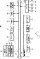
図1は、本発明を適用した通信システム1の一実施の形態の構成を示すブロック図である。この通信システム1においては、アクセスポイント11に、デジタルカメラ12およびパーソナルコンピュータ13が接続され、ネットワーク14に、アクセスポイント11およびパーソナルコンピュータ15が接続されている。 FIG. 1 is a block diagram showing a configuration of an embodiment of a communication system 1 to which the present invention is applied. In this communication system 1, a
アクセスポイント11は、インフラストラクチャ方式の無線LANにより、デジタルスチルカメラ(以下、デジタルカメラと称する)12とパーソナルコンピュータ13との間で送受信されるデータを中継する通信装置の一例である。例えば、アクセスポイント11は、デジタルカメラ12から送信されてくるデータを中継して、パーソナルコンピュータ13に送信するか、またはパーソナルコンピュータ13から送信されてくるデータを中継して、デジタルカメラ12に送信する。 The
また、アクセスポイント11は、ルーティング(Routing)やNAT(Network Address Translation)機能を備えており、例えば、デジタルカメラ12またはパーソナルコンピュータ13から送信されてくるデータを中継して、ネットワーク14に接続されたパーソナルコンピュータ15に送信するか、またはネットワーク14に接続されたパーソナルコンピュータ15から送信されてくるデータを中継して、デジタルカメラ12またはパーソナルコンピュータ13に送信する。 The
デジタルカメラ12は、無線LANにより通信するためのインターフェイス(無線LANカード)を備える、通信装置の一例である。例えば、デジタルカメラ12は、アクセスポイント11を介して、パーソナルコンピュータ13にデータを送信するか、またはパーソナルコンピュータ13からデータを受信する。また、デジタルカメラ12は、被写体を撮像し、撮像の結果得られた画像データを記録する The
パーソナルコンピュータ13は、アクセスポイント11を介して、データをデジタルカメラ12に送信するか、またはデジタルカメラ12から送信されてくるデータを受信する機器の一例である。例えば、パーソナルコンピュータ13は、アクセスポイント11を介して、デジタルカメラ12から送信されてくる、デジタルカメラ12により撮像された画像データを受信し、受信した画像データを記録する。 The
ネットワーク14には、アクセスポイント11およびパーソナルコンピュータ15などが相互に接続されている。ネットワーク14は、有線または無線の、相互に接続されているネットワークまたは通信回線などからなり、例えば、TCP/IP(Transmission Control Protocol/Internet Protocol)などの所定のプロトコルに従って、アクセスポイント11およびパーソナルコンピュータ15を相互に通信させる。 An
パーソナルコンピュータ15は、アクセスポイント11およびネットワーク14を介して、データをデジタルカメラ12に送信するか、またはデジタルカメラ12から送信されてくるデータを受信する機器の一例である。例えば、パーソナルコンピュータ15は、アクセスポイント11およびネットワーク14を介して、デジタルカメラ12から送信されてくる、デジタルカメラ12により撮像された画像データを受信し、受信した画像データを記録する。 The
なお、以下、この実施例において、通信装置の一例としてデジタルカメラ12を説明するが、本発明は、これに限らず、例えば、カムコーダ(カメラ一体型ビデオレコーダ)、PDA(Personal Digital Assistance)、撮像機能付き携帯電話機、または撮像機能付きパーソナルコンピュータなど、撮像機能を有する機器に適用することができる。 In the following, in this embodiment, the
また、上述した例においては、説明を分かり易くするために、アクセスポイント11に接続される機器として、デジタルカメラ12とパーソナルコンピュータ13の2つを例にして説明したが、アクセスポイント11に接続可能な台数の範囲で接続される機器を増やすか、または減らすことが可能である。すなわち、任意の数の機器をアクセスポイント11に接続させることができる。 In the above-described example, for ease of explanation, the
さらに、パーソナルコンピュータ13またはパーソナルコンピュータ15の代わりに、デジタルカメラ、カムコーダ、PDA、または撮像機能付き携帯電話機などのアクセスポイント11またはネットワーク14に接続可能な機器を接続させるようにしてもよい。また、アクセスポイント11は、外部のネットワーク14とは接続せずに、デジタルカメラ12およびパーソナルコンピュータ13とのみ接続する構成にすることも可能である。 Furthermore, instead of the
図2は、アクセスポイント11の機能の構成を示すブロック図である。 FIG. 2 is a block diagram showing a functional configuration of the
制御部21は、汎用のCPU(Central Processing Unit)、MPU(Micro Processing Unit)、または専用のプロセッサなどからなり、アクセスポイント11の各部を制御する。例えば、CPUである制御部21は、メモリ22に記憶されているプログラムを実行することにより、各種の機能を実現し、アクセスポイント11の各部を制御する。 The
また、制御部21は、必要に応じて、データをメモリ22に供給したり、メモリ22が一時的に記憶しているデータを取得する。 In addition, the
制御部21は、設定情報生成部51、符号化部52、および表示制御部53を含むように構成される。例えば、プログラムを実行するCPUである制御部21は、設定情報生成部51、符号化部52、および表示制御部53を実現させる。 The
なお、設定情報生成部51、符号化部52、および表示制御部53をハードウェアにより構成するようにしても、プログラムを実行するコンピュータにより設定情報生成部51、符号化部52、および表示制御部53を実現するようにしてもよい。 Even if the setting
設定情報生成部51は、不正な接続を排除し、正当な相手だけを接続させるための設定情報を生成する。例えば、設定情報生成部51は、入力部23から供給されてくる操作信号に応じて、二項乱数、ポアソン乱数、または正規乱数などの乱数を生成し、生成した乱数を、設定情報の一例であるSSIDまたはWEPキーとすることによって、“abcde123”であるSSIDおよび“xyz1359ab”であるWEPキーを生成し、生成したSSIDおよびWEPキーを、設定情報記憶部26および符号化部52のそれぞれに供給する。 The setting
また、設定情報生成部51は、任意に選択され送信側、受信側において共通の値とされる設定情報を生成する。 In addition, the setting
符号化部52は、設定情報生成部51から供給されたSSIDおよびWEPキーを2次元コードに符号化(エンコード)する。符号化部52は、符号化した2次元コードを表示制御部53に供給する。より具体的には、例えば、符号化部52は、設定情報生成部51から供給された“abcde123”であるSSIDおよび“xyz1359ab”であるWEPキーを2次元コードの一例としてのQRコード(商標)に符号化し、符号化したQRコードを表示制御部53に供給する。 The
すなわち、符号化部52は、設定情報生成部51から供給されたSSIDおよびWEPキーを含む2次元コードを生成する。 That is, the
ここで、2次元コードとは、水平と垂直の二次元方向に情報を持つコードである。2次元コードは、例えば、バーコードなどの一次元コードが、水平方向のみに情報を持っていたのとは違い、水平と垂直の二次元方向に情報を持たせることにより、英数字の文字列以外にも、かなや漢字、文章などもコード化することができ、大容量のデータを扱うことができる。 Here, the two-dimensional code is a code having information in a horizontal and vertical two-dimensional direction. The two-dimensional code is different from the one-dimensional code such as a bar code that has information only in the horizontal direction. In addition, kana, kanji, and sentences can be coded, and large volumes of data can be handled.
また、QRコードとは、日本で開発された2次元コードの中で唯一国際自動認識工業会(AIM International)において、世界規格に認定されたコードであり、その後、日本工業規格(JIS)にも制定されている。QRコードには、大容量の情報を小さいスペースで表現することができるというメリットがあり、例えば、数字のみの情報ならば、最大7089文字の情報をコード化することができる。 The QR code is the only two-dimensional code developed in Japan that has been certified by the International Association of Automatic Recognition Industries (AIM International) as a global standard. It has been enacted. The QR code has an advantage that a large amount of information can be expressed in a small space. For example, if it is information of only numbers, information of a maximum of 7089 characters can be encoded.
なお、この実施例においては、2次元コードの一例として、QRコードについて説明するが、本発明はそれに限らず、例えば、DataMatrix(商標)、PDF417(商標)、サイバーコード(Cyber Code)(商標)などを用いるようにしてもよい。当然、2次元コードは、スタック型でもマトリックス型でもよい。 In this embodiment, a QR code will be described as an example of a two-dimensional code. However, the present invention is not limited to this. For example, DataMatrix (trademark), PDF417 (trademark), Cyber Code (trademark) Etc. may be used. Of course, the two-dimensional code may be a stack type or a matrix type.
表示制御部53は、2次元コードの表示を制御する。例えば、表示制御部53は、符号化部52から供給された、“abcde123”であるSSIDおよび“xyz1359ab”であるWEPキーから符号化されたQRコードを、後述する表示部24の画面に表示させる。 The
入力部23は、スイッチまたはダイヤルなどからなり、ユーザの操作に応じた操作信号を、制御部21に供給する。例えば、入力部23は、アクセスポイント11に無線LAN設定表示ボタンとして設けられ、ユーザにより押下された場合、押下に応じた操作信号を設定情報生成部51に供給する。復号 The
表示部24は、例えば、LCD(Liquid Crystal Display)、有機EL(Electro Luminescence)ディスプレイ、またはLED(Light Emitting Diode)ディスプレイなどから構成され、表示制御部53の制御を基に、2次元コードを表示する。例えば、表示部24は、表示制御部53の制御を基に、“abcde123”であるSSIDおよび“xyz1359ab”であるWEPキーから符号化されたQRコードを表示する。 The
通信部25は、イーサーネットなどの有線LANのインターフェイスから構成され、ネットワーク14を介して、他の機器と接続して、データの送受信をする。例えば、通信部25は、ネットワーク14を介して、パーソナルコンピュータ15と接続して、データの送受信をする。 The
設定情報記憶部26は、例えば、EEPROM(Electronically Erasable and Programmable Read Only Memory)またはフラッシュメモリなどの不揮発性メモリからなり、各種の設定情報を記憶する。すなわち、設定情報は、設定情報記憶部26に記憶されることにより設定される。設定情報記憶部26は、例えば、設定情報生成部51から供給されてくる、アクセスポイント11に接続されるデジタルカメラ12やパーソナルコンピュータ13などの機器において共通に設定されている、SSIDおよびWEPキーを記憶する。 The setting
無線通信部28は、デジタルカメラ12またはパーソナルコンピュータ13などの他の機器と無線により通信する。例えば、無線通信部28は、IEEE802.11a、IEEE802.11b、またはIEEE802.11gの規格に準拠した通信方式で、デジタルカメラ12またはパーソナルコンピュータ13と無線により通信する。 The
例えば、無線通信部28は、信号を受信する場合、制御部21の制御を基に、他の機器から送信されてくる変調波を電波として受信し、受信した変調波に所定の処理を施すことで、データを復調する。無線通信部28は、制御部21の制御を基に、復調したデータを、バス27を介して、メモリ22に記憶させる。また、無線通信部28は、信号を送信する場合、制御部21の制御を基に、メモリ22に記憶されたデータに所定の処理を施すことで、データを変調し、変調したデータを他の機器宛てに送信する。 For example, when receiving a signal, the
なお、無線通信部28が、他の機器と無線により通信する場合、制御部21は、設定情報記憶部26に記憶されている設定情報を基に、無線通信部28の通信を制御する。例えば、制御部21は、他の機器から送信されてきたSSIDと、設定情報記憶部26に記憶されているSSIDとを比較し、送信されてきたSSIDと記憶しているSSIDとが一致したとき、他の機器との無線による通信を開始するように、無線通信部28の通信を制御する。例えば、制御部21は、設定情報記憶部26に記憶されているWEPキーを暗号キーとして、無線通信部28に送信させようとするデータを暗号化するか、または無線通信部28により受信されたデータを復号する。 When the
無線通信部28は、アンテナ61、高周波処理部62、ベースバンド処理部63、およびMAC(Media Access Control)部64を含むように構成される。 The
アンテナ61は、信号を受信する場合、無線通信により、他の機器から送信されてくる変調波を電波として受信する。アンテナ61は、受信した変調波の信号を高周波処理部62に供給する。また、アンテナ61は、信号を送信する場合、高周波処理部62から供給された変調されている信号を、電波として放射する。 When receiving a signal, the
高周波処理部62は、信号を受信する場合、アンテナ61から供給された変調波を、所定の復調方式によって復調する。高周波処理部62は、復調により得られた信号をベースバンド処理部63に供給する。また、高周波処理部62は、信号を送信する場合、ベースバンド処理部63から供給された信号を、所定の変調方式によって変調する。高周波処理部62は、変調された信号(変調波)をアンテナ61に供給する。 When receiving a signal, the high
ベースバンド処理部63は、信号を受信する場合、高周波処理部62から供給された、アナログ信号である信号を、デジタル信号のデータに変換する。ベースバンド処理部63は、変換により生成されたデジタル信号のデータをMAC部64に供給する。また、ベースバンド処理部63は、信号を送信する場合、MAC部64から供給されたデジタル信号のデータを、アナログ信号である信号に変換する。ベースバンド処理部63は、変換により生成された信号を高周波処理部62に供給する。 When receiving the signal, the
MAC部64は、信号を受信する場合、ベースバンド処理部63から供給されたデータを、所定のフォーマットに変換する。例えば、MAC部64は、ベースバンド処理部63から供給されたデータに含まれているヘッダおよび誤り訂正符号(誤り検出符号)などを抽出し、ヘッダを基にデータを送信してきた機器などを特定し、誤り訂正符号を基に受信したデータの誤りを訂正するなどして、ヘッダおよび誤り訂正符号などを取り除いた方式のデータに変換する。AC部64は、所定のフォーマットに変換されたデータを、バス27を介して、メモリ22に記憶させるか、または制御部21に供給する。 When receiving the signal, the
また、MAC部64は、信号を送信する場合、送信しようとするデータを、所定のフォーマットに変換する。例えば、MAC部64は、メモリ22から送信しようとするデータを読み出して、読み出したデータにヘッダおよび誤り訂正符号(誤り検出符号)などを付加することにより、所定のフォーマットに変換する。MAC部64は、所定のフォーマットに変換されたデータをベースバンド処理部63に供給する。 Further, when transmitting a signal, the
ドライブ29は、必要に応じてアクセスポイント11に接続される。ドライブ29には、磁気ディスク41(例えば、HDD(Hard Disk))、光ディスク42(例えば、CD(Compact Disc)やDVD(Digital Versatile Disc))、光磁気ディスク43(例えば、MD(Mini-Disc)(商標))、または半導体メモリ44(例えば、メモリカード)が適時装着される。ドライブ29は、装着された磁気ディスク41、光ディスク42、光磁気ディスク43、または半導体メモリ44から記録されているプログラムを読み出して、読み出したプログラムを制御部21に供給する。 The
このように、制御部21は、記録媒体の一例である磁気ディスク41、光ディスク42、光磁気ディスク43、または半導体メモリ44から読み出されたプログラムを実行することができる。 As described above, the
図3は、デジタルカメラ12の機能の構成を示すブロック図である。 FIG. 3 is a block diagram illustrating a functional configuration of the
カメラ部101は、例えば、撮像素子と、撮像素子に映像を結像させるレンズなどの光学系、および所定の信号処理を行う回路などから構成される。カメラ部101は、撮像制御部141の制御を基に、被写体の像を結像させて、結像させた画像を光電変換して、画像に対応する画像データを生成する。カメラ部101は、撮像制御部141の制御を基に、生成した画像データに対して、所定の信号処理を適用し、所定の信号処理が施された画像データを、ドライブ109に供給することで、記録媒体110に記録させる。 The
カメラ部101は、光学ブロック131、CCD(Charge Coupled Devices)132、A/D(Analog/Digital)変換部133、および信号処理部134を含むように構成される。 The
光学ブロック131は、例えば、光学レンズ、フォーカス機構、シャッタ機構、および絞り(アイリス)機構などから構成され、被写体に反射した光を像として集め、すなわち、被写体の光学的な像をCCD132の受光部に結像させる。 The
CCD132は、CCDセンサから構成され、光学ブロック131により結像された被写体の光学的な像を光電変換することにより、アナログの電気信号である画像信号に変換する。CCD132は、変換の結果得られたアナログの電気信号である画像信号をA/D変換部133に供給する。 The
なお、CCD132を一例としてあげた光電変換素子は、CCDセンサに限らず、例えば、CMOS(Complementary Metal Oxide Semiconductor)センサなど、光学的な画像を電気信号に変換できる撮像素子であればよい。 Note that the photoelectric conversion element taking the
A/D変換部133は、CCD132から供給されたアナログ信号である画像信号を、デジタル信号である画像データに変換する。A/D変換部133は、変換により生成されたデジタル信号である画像データを信号処理部134に供給する。 The A /
信号処理部134は、A/D変換部133から供給されるデジタル信号である画像データに対して、所定の信号処理を適用する。 The
例えば、信号処理部134は、A/D変換部133から供給される画像データを、バス102を介して、メモリ103に記憶させることで、メモリ103に記憶された画像データを適宜読み出し、読み出した画像データに対して、利得を制御するAGC(Automatic Gain Control)処理、画像データの値(画素値)を補正することにより、白色などの予め定められた基準の色を基に全体の画像データにより表示される画像の色調を補正するAWB(Auto White Balance)処理、被写体に焦点(ピント)を合わせるAF(Auto Focus)処理、および被写体の明るさを基に露出を決定するAE(Auto Exposure)処理などの信号処理を適用する。 For example, the
さらに、例えば、信号処理部134は、A/D変換部133から供給される画像データを基に、光学ブロック131を制御し、被写体に焦点(ピント)を合わさせるAF(Auto Focus)処理を実行する。 Further, for example, the
また、信号処理部134は、信号処理が施された画像データを、例えば、JPEG(Joint Photographic Experts Group)方式などの所定の静止画像(データ)を圧縮符号化する圧縮符号化方式で符号化する。信号処理部134は、バス102を介して、圧縮した画像データをドライブ109に供給し、記録媒体110(例えば、半導体メモリ124)に画像データを記録させる。 Further, the
さらに、信号処理部134は、スイッチ、コントロールキー、または表示部106の画面に設けられているタッチパネルなどの入力部105へのユーザからの操作入力に応じて、ユーザが所望する画像データが記録媒体110から読み出された場合、バス102を介して、記録媒体110から供給された圧縮符号化されている画像データを、圧縮符号化方式に応じて復号することで、画像データを伸張し、伸張した画像データを、バス102を介して、表示部106に供給して、画像を表示させる。 Furthermore, the
制御部104は、汎用のCPU、MPU、または専用のプロセッサなどからなり、デジタルカメラ12の各部を制御する。例えば、CPUである制御部104は、メモリ103に記憶されているプログラムを実行することにより、各種の機能を実現し、デジタルカメラ12の各部を制御する。 The
また、制御部104は、必要に応じて、データをメモリ103に供給したり、メモリ103が一時的に記憶しているデータを取得する。 Further, the
制御部104は、撮像制御部141、復号部142、および設定情報記憶制御部143を含むように構成される。例えば、プログラムを実行するCPUである制御部104は、撮像制御部141、復号部142、および設定情報記憶制御部143を実現させる。 The
なお、撮像制御部141、復号部142、および設定情報記憶制御部143をハードウェアにより構成するようにしても、プログラムを実行するコンピュータにより撮像制御部141、復号部142、および設定情報記憶制御部143を実現するようにしてもよい。 Even if the
撮像制御部141は、カメラ部101を制御して、被写体の像を結像させた画像を光電変換させて、画像に対応する画像データを生成させる。撮像制御部141は、カメラ部101を制御して、生成した画像データに対して、所定の信号処理を適用させて、所定の信号処理が施された画像データを、ドライブ109に供給させることで、記録媒体110に記録させる。 The
復号部142は、メモリ103に記憶されている2次元コードの画像データを復号(デコード)する。例えば、復号部142は、メモリ103に記憶されている、QRコード203の画像データを復号する。 The decoding unit 142 decodes (decodes) the two-dimensional code image data stored in the
設定情報記憶制御部143は、復号の結果得られたデータから、SSIDおよびWEPキーを取得して(抽出して)、取得したSSIDおよびWEPキーを設定情報記憶部107に供給する。例えば、設定情報記憶制御部143は、復号の結果得られたデータから、“abcde123”であるSSIDおよび“xyz1359ab”であるWEPキーを取得し、取得したSSIDおよびWEPキーを設定情報記憶部107に供給する。 The setting information
入力部105は、例えば、ユーザが撮影を行うためのシャッタレリーズボタン、表示部109の画面に設けられるタッチパネル、またはコントロールキー(スイッチ)(図示せず)などから構成され、ユーザの操作(入力)に対応する操作信号を制御部104に供給する。 The
表示部106は、例えば、LCD、有機ELディスプレイ、またはLEDディスプレイなどから構成され、各種の画像または文字列などを表示する。例えば、表示部106は、信号処理部134から供給された、復号された画像データにより表示される画像を表示する。また、表示部106は、ユーザの操作に応じて、制御部104が起動させたアプリケーションプログラムのユーザインターフェイスの画像を表示する。 The
設定情報記憶部107は、例えば、EEPROMまたはフラッシュメモリなどの不揮発性メモリからなり、各種の設定情報を記憶する。すなわち、設定情報は、設定情報記憶部107に記憶されることにより、設定される。 The setting
例えば、設定情報記憶部107は、設定情報記憶制御部143から供給された“abcde123”であるSSIDおよび“xyz1359ab”であるWEPキーを記憶することにより、設定する。 For example, the setting
無線通信部108は、アクセスポイント11と無線により通信する。例えば、無線通信部108は、IEEE802.11a、IEEE802.11b、またはIEEE802.11gの規格に準拠した通信方式で、他の機器と無線により通信する。 The
例えば、無線通信部108は、信号を受信する場合、制御部104の制御に従って、アクセスポイント11から送信されてくる変調波を電波として受信し、受信した変調波に所定の処理を施すことで、データを復調する。無線通信部108は、制御部104の制御の基に、復調したデータを、バス102を介して、メモリ103に記憶させる。また、無線通信部108は、信号を送信する場合、制御部104の制御の基に、メモリ103に記憶されたデータに所定の処理を施すことで、データを変調し、変調したデータをアクセスポイント11に送信する。 For example, when receiving a signal, the
無線通信部108は、アンテナ151、高周波処理部152、ベースバンド処理部153、およびMAC部154を含むように構成される。 The
アンテナ151は、信号を受信する場合、無線通信により、アクセスポイント11から送信されてくる変調波を電波として受信する。アンテナ151は、受信した変調波の信号を高周波処理部152に供給する。また、アンテナ151は、信号を送信する場合、高周波処理部152から供給された変調されている信号を、電波として放射する。 When receiving a signal, the
高周波処理部152は、信号を受信する場合、アンテナ151から供給された変調波を、所定の復調方式によって復調する。高周波処理部152は、復調により得られた信号をベースバンド処理部153に供給する。また、高周波処理部152は、信号を送信する場合、ベースバンド処理部153から供給された信号を、所定の変調方式によって変調する。高周波処理部152は、変調された信号(変調波)をアンテナ151に供給する。 When receiving a signal, the high
ベースバンド処理部153は、信号を受信する場合、高周波処理部152から供給された、アナログ信号である信号を、デジタル信号のデータに変換する。ベースバンド処理部153は、変換により生成されたデジタル信号のデータをMAC部154に供給する。また、ベースバンド処理部153は、信号を送信する場合、MAC部154から供給されたデジタル信号のデータを、アナログ信号である信号に変換する。ベースバンド処理部153は、変換により生成された信号を高周波処理部152に供給する。 When the
MAC部154は、信号を受信する場合、ベースバンド処理部153から供給されたデータを、所定のフォーマットに変換する。例えば、MAC部154は、ベースバンド処理部153から供給されたデータに含まれているヘッダおよび誤り訂正符号(誤り検出符号)などを抽出し、ヘッダを基にデータを送信してきたアクセスポイント11を特定し、誤り訂正符号を基に受信したデータの誤りを訂正するなどして、ヘッダおよび誤り訂正符号などを取り除いた方式のデータに変換する。MAC部154は、所定のフォーマットに変換されたデータをメモリ103に記憶させるか、または制御部104に供給する。 When receiving the signal, the
また、MAC部154は、信号を送信する場合、送信しようとするデータを、所定のフォーマットに変換する。例えば、MAC部154は、メモリ103から送信しようとするデータを読み出して、読み出したデータにヘッダおよび誤り訂正符号(誤り検出符号)などを付加することにより、所定のフォーマットに変換する。MAC部154は、所定のフォーマットに変換されたデータをベースバンド処理部153に供給する。 Further, when transmitting a signal, the
ドライブ109は、装着された記録媒体110にデータを書き込むか、または装着された記録媒体110からデータまたはプログラムを読み出す。例えば、ドライブ109は、記録媒体110がメモリカードの場合、そのメモリカードに対応した所定のインターフェイスで構成される。 The
記録媒体110は、例えば、磁気ディスク121(例えば、HDD)、光ディスク122(例えば、CDやDVD)、光磁気ディスク123(例えば、MD(商標))、または半導体メモリ124(例えば、メモリカード)などから構成される。記録媒体110は、着脱可能にドライブ109に装着される。 The
また、ドライブ109は、装着された磁気ディスク121、光ディスク122、光磁気ディスク123、または半導体メモリ124から記録されているプログラムを読み出して、読み出したプログラムを制御部104に供給する。 Further, the
このように、制御部104は、磁気ディスク121、光ディスク122、光磁気ディスク123、または半導体メモリ124などの記録媒体110から読み出されたプログラムを実行することができる。 As described above, the
次に、図4を参照して、アクセスポイント11およびデジタルカメラ12におけるレイヤ構成の例について説明する。 Next, an example of a layer configuration in the
例えば、アクセスポイント11およびデジタルカメラ12は、ハードウェア、ドライバ、プロトコル、およびアプリケーションの4階層からなるレイヤ構成に従って各種の処理を実現している。 For example, the
ハードウェアは、例えば、無線LANカードまたは不揮発性メモリなどの、電子回路やデバイスなどの物理的実体に対応する。 The hardware corresponds to a physical entity such as an electronic circuit or a device such as a wireless LAN card or a nonvolatile memory.
ハードウェアは、OSI(Open Systems Interconnection)参照モデルの物理層にあたり、無線LANの場合、デジタル信号を非常に小さい電力で広い帯域に分散させて同時に送信する方式である直接拡散方式(DSSS(Direct Sequence Spread Spectrum))、極めて短い時間ごとに信号を送信する周波数を変更して送信する方式である周波数ホッピング方式(FHSS(Frequency Hopping Spectrum Spread))、または赤外線などのいずれかの方式に対応している。 The hardware is the physical layer of the OSI (Open Systems Interconnection) reference model, and in the case of a wireless LAN, the direct spreading method (DSSS (Direct Sequence), which is a method of simultaneously transmitting digital signals distributed over a wide band with very little power, Spread Spectrum)), frequency hopping (FHSS (Frequency Hopping Spectrum Spread)), which is a method of changing the frequency at which signals are transmitted every very short time, or infrared. .
ドライバは、例えば、周辺機器などのハードウェアを動作させるためのソフトウェア(プログラム)である。プログラムであるドライバは、コンピュータである制御部21または制御部104により実行される。 The driver is, for example, software (program) for operating hardware such as peripheral devices. A driver that is a program is executed by the
例えば、アクセスポイント11において、ドライバは、ハードウェアからMACアドレスを取得し、取得したMACアドレスをアプリケーションに供給する。また、ドライバは、アプリケーションが生成したSSIDおよびWEPキーを、例えば、不揮発性メモリなどのハードウェアに記憶させる。 For example, in the
さらに、例えば、デジタルカメラ12において、ドライバは、アプリケーションが2次元コードを復号し、復号した結果得られたSSIDおよびWEPキーを、例えば、不揮発性メモリなどのハードウェアに記憶させる。 Further, for example, in the
また、ドライバは、OSI参照モデルのデータリンク層にあたり、さらに、データリンク層は、上位の層となるLLC(Logical Link Control)層と下位の層となるMAC層から構成される。無線LANの場合、下位のMAC層において、無線LANにおける物理層およびMAC層に関する規格が取り決めされている。例えば、MAC層には、IEEE802.11規格や、他の機器が信号を送信していないことを確かめてからデータを送出する方式であるCSMA/CA(Carrier Sense Multiple Access with Collision Avoidance)方式に対応していることなどが規定されている。 The driver corresponds to the data link layer of the OSI reference model, and the data link layer further includes an LLC (Logical Link Control) layer as an upper layer and a MAC layer as a lower layer. In the case of a wireless LAN, standards related to the physical layer and the MAC layer in the wireless LAN are negotiated in the lower MAC layer. For example, the MAC layer supports the IEEE 802.11 standard and the CSMA / CA (Carrier Sense Multiple Access with Collision Avoidance) method, which sends data after confirming that no other device is transmitting signals. It is stipulated that
プロトコルは、機器間でデータ通信を行う際の規約であり、例えば、アクセスポイント11およびデジタルカメラ12は、TCP/IPなどの所定のプロトコルに従って、相互に通信を行う。例えば、プロトコルは、ソフトウェア(プログラム)により実現され、プログラムであるプロトコルは、コンピュータである制御部21および制御部104により実行される。 The protocol is a rule for data communication between devices. For example, the
また、プロトコルは、OSI参照モデルのネットワーク層とトランスポート層に対応する。プロトコルは、ネットワーク層におけるデータを送信する経路の選定(ルーティング)をするための方法の定義や、IP(Internet Protocol)アドレスやパケットのサイズの変換方法などを規定したり、トランスポート層におけるTCP(Transmission Control Protocol)やUDP(User Datagram Protocol)、誤り訂正データ転送の方法など、データ転送の信頼性に関することを規定する。 The protocol corresponds to the network layer and transport layer of the OSI reference model. The protocol defines the method for selecting the route for transmitting data in the network layer (routing), specifies the IP (Internet Protocol) address and packet size conversion method, etc., and the TCP ( It stipulates data transfer reliability such as Transmission Control Protocol (UDP), User Datagram Protocol (UDP), and error correction data transfer method.
アプリケーションは、例えば、無線LANの設定に関する処理など、ある特定の目的のために設計されたソフトウェア(アプリケーションプログラム)に対応する。 The application corresponds to software (application program) designed for a specific purpose, for example, processing related to wireless LAN setting.
例えば、アクセスポイント11において、アプリケーションプログラムは、SSIDおよびWEPキーを生成する。また、アプリケーションプログラムは、生成したSSIDおよびWEPキーと、ドライバがハードウェアから取得するMACアドレスを基に、2次元コードを生成し(SSID、WEPキー、およびMACアドレスを2次元コードに符号化し)、生成した2次元コードを、例えば、LCDなどからなる表示部24であるハードウェアに表示させる。 For example, in the
また、例えば、デジタルカメラ12において、アプリケーションは、2次元コードを復号し、復号した結果得られたSSIDおよびWEPキーをドライバに供給する。 For example, in the
さらに、アプリケーションは、OSI参照モデルのセッション層、プレゼンテーション層、アプリケーション層に対応する。アプリケーションは、セッション層における機器間のコネクションや切断などを規定したり、プレゼンテーション層における圧縮形式や文字コードなどといった、データ表現を規定したり、アプリケーション層における、特に、ユーザの操作に直接関わる処理を規定している。 Furthermore, the application corresponds to the session layer, presentation layer, and application layer of the OSI reference model. The application prescribes connection and disconnection between devices in the session layer, prescribes data representation such as compression format and character code in the presentation layer, and performs processing directly related to user operations in the application layer. It stipulates.
次に、図5のフローチャートを参照して、アクセスポイント11による、設定情報表示の処理について説明する。 Next, setting information display processing by the
ステップS11において、制御部21は、初期化処理を実行する。例えば、ステップS11において、制御部21は、ユーザにより、アクセスポイント11に設けられた初期化スイッチ(図示せず)が押下された場合、設定された設定情報(SSIDおよびWEPキーなど)を初期化(クリア)するとともに、設定情報記憶部26に記憶された設定情報(SSIDおよびWEPキーなど)も初期化(クリア)する。 In step S11, the
また、初期化処理を実行した場合、設定情報が初期化される(例えば、工場出荷時設定に戻る)ので、アクセスポイント11およびアクセスポイント11を中継局とする無線LANセグメントに接続される機器に、再度、設定情報を設定する必要がある。この場合、例えば、アクセスポイント11、デジタルカメラ12、およびパーソナルコンピュータ13に対して、再度、設定情報を設定する必要がある。 Also, when the initialization process is executed, the setting information is initialized (for example, returns to the factory default setting), so that the
すなわち、図5を参照して説明する設定情報表示の処理は、(購入時などに)新規で設定情報を設定するか、または既に設定していた設定情報を初期化して、再度、設定情報を設定する場合の処理となる。 That is, the setting information display process described with reference to FIG. 5 is performed by setting new setting information (for example, at the time of purchase) or initializing setting information that has already been set, and setting information again. This is the process for setting.
ステップS12において、制御部21は、入力部23から供給される操作信号を基に、ユーザにより、アクセスポイント11に設けられた入力部23である無線LAN設定表示ボタン(例えば、後述する図7の無線LAN設定表示ボタン201)が押下されたか否かを判定する。 In step S12, the
ステップS12において、無線LAN設定表示ボタンが押下されていないと判定された場合、ユーザからの設定情報の表示が指示されていないので、ステップS12に戻り、上述した処理を繰り返す。すなわち、ユーザによって、無線LAN設定表示ボタンが押下されるまで、ステップS12の処理が繰り返される。 If it is determined in step S12 that the wireless LAN setting display button has not been pressed, the display of setting information from the user has not been instructed, so the process returns to step S12 and the above-described processing is repeated. That is, the process of step S12 is repeated until the user presses the wireless LAN setting display button.
一方、ステップS12において、無線LAN設定表示ボタンが押下されたと判定された場合、ユーザから設定情報の表示が指示されたので、ステップS13に進み、設定情報生成部51は、二項乱数、ポアソン乱数、または正規乱数などの乱数を生成し、生成した乱数をSSIDおよびWEPとすることによって、SSIDおよびWEPキーを生成し、生成したSSIDおよびWEPキーを、設定情報記憶部26および符号化部52にそれぞれ供給する。 On the other hand, if it is determined in step S12 that the wireless LAN setting display button has been pressed, since the user has instructed display of setting information, the process proceeds to step S13, where the setting
ここで、上述したように、SSIDおよびWEPキーを初期化したので(ステップS11の処理)、インフラストラクチャ方式の無線LANによって通信を行う場合、アクセスポイント11およびアクセスポイント11を中継局とする無線LANセグメントに接続される各機器に、共通の無線LANで特定のネットワークを指定するための識別子であるSSIDと、データを暗号化するための暗号鍵であるWEPキーとを設定する必要がある。 Here, as described above, since the SSID and the WEP key are initialized (the process of step S11), when communication is performed using an infrastructure wireless LAN, the wireless LAN using the
具体的には、SSIDは、32バイト以内の英数字の組み合わせた任意の文字列である。一般的に、同じ周波数帯を用いて複数のLANセグメントを構築した場合、混信する可能性があるので、SSIDの値によって参加する無線LANセグメントを認識させることで、SSIDが異なる機器は通信を行うことができなくなる。 Specifically, the SSID is an arbitrary character string in which alphanumeric characters within 32 bytes are combined. In general, when multiple LAN segments are built using the same frequency band, there is a possibility of interference, so devices with different SSIDs communicate by recognizing participating wireless LAN segments according to the SSID value. I can't do that.
また、WEPキーは、8バイト(64ビット)または16バイト(128ビット)などの文字列からなり、任意に設定される、キーを生成するための値である。より正確には、WEPによる暗号化では、データの暗号化または復号に実際に用いる鍵がWEPキーを基に生成され、生成された鍵を送信側および受信側において共通鍵とすることによって、送信されるデータが暗号化され、受信したデータが復号される。 The WEP key is a value for generating a key, which is arbitrarily set and consists of a character string of 8 bytes (64 bits) or 16 bytes (128 bits). More precisely, in encryption by WEP, a key that is actually used for data encryption or decryption is generated based on the WEP key, and the generated key is used as a common key on the transmission side and the reception side to transmit the key. Data is encrypted and the received data is decrypted.
すなわち、同一のセグメントの無線LANを使用するためには、同一のSSIDとWEPキーを設定する必要がある。なお、WEPキーを指定しない場合でも通信をすることは可能であるが、WEPキーを指定することで、データを暗号化することができるので、秘匿性を向上させることができる。 That is, in order to use the same segment wireless LAN, it is necessary to set the same SSID and WEP key. Although communication is possible even when the WEP key is not specified, data can be encrypted by specifying the WEP key, so that confidentiality can be improved.
例えば、ステップS13において、設定情報生成部51は、二項乱数、ポアソン乱数、または正規乱数などの乱数によって、“abcde123”であるSSIDおよび“xyz1359ab”であるWEPキーを生成し、生成したSSIDおよびWEPキーを、設定情報記憶部26に供給するか、または設定情報記憶部26および符号化部52のそれぞれに供給する。 For example, in step S13, the setting
ステップS14において、設定情報記憶部26は、設定情報生成部51から供給されたSSIDおよびWEPキーを記憶する。例えば、ステップS14において、設定情報記憶部26は、設定情報生成部51から供給された“abcde123”であるSSIDおよび“xyz1359ab”であるWEPキーを記憶する。 In step S <b> 14, the setting
すなわち、設定情報記憶部26がSSIDおよびWEPキーなどの設定情報を記憶することで、アクセスポイント11には、設定情報が設定されることになる。例えば、設定情報記憶部26が“abcde123”であるSSIDおよび“xyz1359ab”であるWEPキーを記憶することで、アクセスポイント11による無線LANに接続する機器のそれぞれには、SSIDとして、“abcde123”を設定し、WEPキーとして、“xyz1359ab”を設定する必要がある。 That is, the setting
また、詳細は後述するが、設定情報記憶部26がSSIDおよびWEPキーを記憶しておくことで、他の機器に対して、SSIDおよびWEPキーを設定する場合、設定情報記憶部26に記憶されたSSIDおよびWEPキーを読み出して、同一のSSIDおよびWEPキーを設定させることが可能となるので、他の機器を、アクセスポイント11による無線LANセグメントに接続させることができる。 As will be described in detail later, when the setting
ステップS15において、符号化部52は、設定情報記憶部26から、記憶されているSSIDおよびWEPキーを読み出し、読み出したSSIDおよびWEPキーを2次元コードに符号化し、符号化した2次元コードを表示制御部53に供給する。すなわち、ステップS15において、符号化部52は、設定されている設定情報であって、不正な情報を排除し、正当な相手だけを接続させるための設定情報であるSSIDおよびWEPキーを2次元コードに符号化する。例えば、ステップS15において、符号化部52は、設定情報記憶部26に記憶されている“abcde123”であるSSIDおよび“xyz1359ab”であるWEPキーをQRコードに符号化し、符号化したQRコードを表示制御部53に供給する。 In step S15, the
なお、ステップS15において、符号化部52は、設定情報生成部51から供給されたSSIDおよびWEPキーを2次元コードに符号化し、符号化した2次元コードを表示制御部53に供給するようにしてもよい。 In step S15, the
図6は、2次元コードに符号化される設定情報の具体例を説明する図である。 FIG. 6 is a diagram for explaining a specific example of setting information encoded into a two-dimensional code.
設定情報の先頭には、ヘッダが配置される。ヘッダには、例えば、設定情報であることを示す、特定の配列からなる識別情報、設定情報を示す2次元コードの方式のバージョンを示すバージョン情報やヘッダそのもののデータ量(バイト数)を示すヘッダ長などの情報が格納される。 A header is arranged at the top of the setting information. The header includes, for example, identification information including a specific array indicating the setting information, version information indicating the version of the two-dimensional code method indicating the setting information, and a header indicating the data amount (number of bytes) of the header itself. Information such as length is stored.
ヘッダの次に4バイトの識別コードが配置され、識別コードに続いて、6バイトのMACアドレスが配置される。識別コードは、MACアドレスを識別するためのコードで、MACアドレスを識別するための識別コード固有のデータ配列からなる。また、MACアドレスは、3バイトのメーカコードと3バイトの製造番号からなり、各メーカのメーカコードと、そのメーカ内での固有のID(Identity)となる製造番号とを組み合わせることで、機器に対して一意の値となっている。 A 4-byte identification code is arranged next to the header, and a 6-byte MAC address is arranged following the identification code. The identification code is a code for identifying the MAC address, and consists of a data array unique to the identification code for identifying the MAC address. The MAC address consists of a 3-byte manufacturer code and a 3-byte manufacturing number. By combining each manufacturer's manufacturer code with a manufacturing number that is a unique ID (Identity) within that manufacturer, It is a unique value.
MACアドレスの次に4バイトの識別コードが配置され、識別コードに続いて、32バイトのSSIDが配置される。識別コードは、SSIDを識別するためのコードで、SSIDを識別するための識別コード固有のデータ配列からなる。また、SSIDとして、例えば、“abcde123”のように、32バイト以内のデータが格納される。 A 4-byte identification code is arranged next to the MAC address, and a 32-byte SSID is arranged following the identification code. The identification code is a code for identifying the SSID, and includes a data array unique to the identification code for identifying the SSID. Further, as SSID, for example, data of 32 bytes or less is stored as “abcde123”.
SSIDの次に4バイトの識別コードが配置され、識別コードに続いて、8バイトまたは16バイトのWEPキーが配置される。識別コードは、WEPキーを識別するためのコードで、WEPキーを識別するための識別コード固有のデータ配列からなる。また、WEPキーとして、例えば、“xyz1359ab”のように、16バイト以内のデータが格納される。 A 4-byte identification code is arranged next to the SSID, and an 8-byte or 16-byte WEP key is arranged following the identification code. The identification code is a code for identifying the WEP key, and includes a data array unique to the identification code for identifying the WEP key. Further, as the WEP key, for example, data of 16 bytes or less is stored as “xyz1359ab”.
アクセスポイント11は、このような形式の設定情報を2次元コードに符号化するので、2次元コードを読み取る側の機器(例えば、デジタルカメラ12)では、識別コードを基に、2次元コードから、MACアドレス、SSID、またはWEPキーの値を確実に取得することができる。また、このようにすることで、2次元コードを読み取る側の機器(例えば、デジタルカメラ12)が、識別コードを格納していない2次元コードから、その2次元コードに含まれるデータを、MACアドレス、SSID、またはWEPキーとして取得してしまうことを防止することができる。 Since the
なお、上述した、設定情報の各データのデータ量は、一例であり、例えば、識別コードのデータ量を4バイトではなく、2バイトにすることも可能である。また、これらのデータ量を固定長とせずに、可変長とすることも可能である。 Note that the data amount of each data of the setting information described above is an example. For example, the data amount of the identification code can be 2 bytes instead of 4 bytes. In addition, these data amounts can be variable lengths instead of fixed lengths.
図5のフローチャートに戻り、ステップS16において、表示制御部53は、符号化部52から供給された2次元コードを表示部24の画面に表示させる。例えば、ステップS16において、表示制御部53は、符号化部52から供給された、“abcde123”であるSSIDおよび“xyz1359ab”であるWEPキーが符号化されたQRコードを表示部24の画面に表示させる。 Returning to the flowchart of FIG. 5, in step S <b> 16, the
図7は、2次元コードを表示する、アクセスポイント11の外観を示す図である。 FIG. 7 is a diagram illustrating an appearance of the
アクセスポイント11には、入力部23としての無線LAN設定表示ボタン201および表示部24の画面202が設けられている。例えば、表示部24の画面202は、無線LAN設定表示ボタン201の近傍に設けられている。 The
ユーザが無線LAN設定表示ボタン201を押下した場合、表示部24の画面202には、QRコード(2次元コード)203が表示される。例えば、表示部24の画面202には、ユーザが無線LAN設定表示ボタン201を押下する(ステップS12の処理)ことにより、“abcde123”であるSSIDおよび“xyz1359ab”であるWEPキーが符号化されたQRコード203が表示される(ステップS16の処理)。 When the user presses the wireless LAN setting
図5のフローチャートに戻り、ステップS17において、制御部21は、入力部23から供給される操作信号を基に、ユーザにより、アクセスポイント11に設けられた無線LAN設定表示ボタン201が押下されたか否かを判定する。 Returning to the flowchart of FIG. 5, in step S <b> 17, the
ステップS17において、無線LAN設定表示ボタン201が押下されたと判定された場合、ユーザから2次元コードの表示の終了が指示されたので、ステップS19に進み、表示制御部53は、表示部24に、2次元コードの表示を消させる。例えば、ステップS19において、表示制御部53は、表示部24に、表示部24の画面202に表示されていた“abcde123”であるSSIDおよび“xyz1359ab”であるWEPキーが符号化されたQRコード203の表示を消させる。 If it is determined in step S17 that the wireless LAN setting
一方、ステップS17において、無線LAN設定表示ボタン201が押下されていないと判定された場合、ステップS18に進み、制御部21は、2次元コードを表示部24に表示してから、所定の時間(例えば、30秒)が経過したか否かを判定する。 On the other hand, if it is determined in step S17 that the wireless LAN setting
ステップS18において、所定の時間が経過していないと判定された場合、ステップS17に戻り、上述した処理を繰り返す。すなわち、ステップS17およびステップS18の処理を繰り返すことで、ユーザにより無線LAN設定表示ボタン201が押下されるか、または所定の時間が経過した場合、表示部24の画面202に表示された2次元コード(QRコード203)の表示が消されることになる。 If it is determined in step S18 that the predetermined time has not elapsed, the process returns to step S17 and the above-described processing is repeated. That is, by repeating the processing of step S17 and step S18, the two-dimensional code displayed on the
一方、ステップS18において、所定の時間が経過したと判定された場合、ステップS19に進み、表示制御部53は、表示部24から2次元コードの表示を消して、処理は終了する。 On the other hand, if it is determined in step S18 that the predetermined time has elapsed, the process proceeds to step S19, where the
このように、本発明によれば、SSIDやWEPキーなどの設定情報を2次元コードに符号化し、符号化した2次元コードを無線LANに接続させる機器に読み取らせることで、簡単に無線LANの設定をすることができるため、ネットワークに関する専門的な知識を有さないユーザであっても無線LANの設定をすることができる。 As described above, according to the present invention, setting information such as SSID and WEP key is encoded into a two-dimensional code, and the encoded two-dimensional code is read by a device connected to the wireless LAN. Since it can be set, even a user who does not have specialized knowledge about the network can set the wireless LAN.
次に、図8のフローチャートを参照して、デジタルカメラ12による、設定情報設定の処理について説明する。 Next, setting information setting processing by the
ステップS31において、制御部104は、入力部105から供給される操作信号を基に、ユーザにより、表示部106の画面に表示されたメニュー画面の無線LAN設定コマンドが選択されたか否かを判定する。 In step S <b> 31, the
ここで、メニュー画面の無線LAN設定コマンドとは、各種の設定を行うメニュー画面に配置されるコマンドのうち、無線LANの設定を実行させるコマンドである。また、デジタルカメラ12は、無線LAN設定コマンドが選択された場合、被写体を撮像する“撮像モード”から、各種機器の設定を行う“設定モード”にモードを変更する。 Here, the wireless LAN setting command on the menu screen is a command for executing wireless LAN setting among commands arranged on the menu screen for performing various settings. In addition, when the wireless LAN setting command is selected, the
ステップS31において、メニュー画面の無線LAN設定コマンドが選択されていないと判定された場合、ステップS31に戻り、上述した処理を繰り返す。すなわち、ユーザにより、メニュー画面の無線LAN設定コマンドが選択されるまで、ステップS31の処理を繰り返すことで、その間、デジタルカメラ12は、“撮像モード”で動作することになる。 If it is determined in step S31 that the wireless LAN setting command on the menu screen has not been selected, the process returns to step S31 and the above-described processing is repeated. That is, the process of step S31 is repeated until the user selects the wireless LAN setting command on the menu screen, and the
一方、ステップS31において、メニュー画面の無線LAN設定コマンドが選択されたと判定された場合、ステップS32に進み、制御部104は、メモリ103に記憶されている無線LAN設定のアプリケーションプログラムを起動する。 On the other hand, if it is determined in step S <b> 31 that the wireless LAN setting command on the menu screen has been selected, the process proceeds to step S <b> 32, and the
ここで、無線LAN設定のアプリケーションプログラムとは、デジタルカメラ12における無線LANに関する設定を行うためのプログラムである。また、無線LAN設定のアプリケーションプログラムは、図4の4階層からなるレイヤ構成の具体例のうち、アプリケーションに対応するプログラムである。 Here, the wireless LAN setting application program is a program for performing settings related to the wireless LAN in the
ステップS33において、撮像制御部141は、CCD132に、ユーザの操作に従って、アクセスポイント11の表示部24に表示されている2次元コードを撮像させる。例えば、ステップS33において、撮像制御部141は、CCD132に、ユーザの操作に従って、アクセスポイント11の表示部24の画面202に表示されている、“abcde123”であるSSIDおよび“xyz1359ab”であるWEPキーが符号化されたQRコード203を撮像させる。 In step S <b> 33, the
詳細に説明すれば、CCD132は、撮像したQRコード203の画像データをA/D変換部133に供給する。A/D変換部133は、CCD132から供給されたアナログデータである2次元コードの画像データを、デジタルデータに変換し、変換により得られたデジタルデータである2次元コードの画像データを信号処理部134に供給する。 More specifically, the
信号処理部134は、A/D変換部133から供給されてくる2次元コードの画像データに対して、所定の処理を施して、所定の処理を施したデータをメモリ103に記憶させる。例えば、信号処理部134は、A/D変換部133から供給されてくるQRコード203の画像データに対して、AGC処理、AWB処理、AF処理、およびAE処理などの所定の処理を施して、所定の処理を施したデータをメモリ103に記憶させる。 The
図9は、アクセスポイント11の表示部24の画面202に表示されるQRコード203を撮像するデジタルカメラ12について説明する図である。 FIG. 9 is a diagram illustrating the
図7に示す場合と同様の部分には、同一の符号が付してあり、その説明は(適宜)省略する。 The same parts as those shown in FIG. 7 are denoted by the same reference numerals, and description thereof will be omitted (as appropriate).
アクセスポイント11の表示部24の画面202には、ユーザが無線LAN設定表示ボタン201を押下することにより、“abcde123”であるSSIDおよび“xyz1359ab”であるWEPキーが符号化されたQRコード203が表示されるので、ユーザは、デジタルカメラ12の入力部105のシャッタレリーズボタンを押下することにより、デジタルカメラ12に、画面202に表示されたQRコード203を撮像させる。 On the
図8のフローチャートに戻り、ステップS34において、復号部142は、メモリ103に記憶されている2次元コードの画像データを復号(解析)する。例えば、ステップS34において、復号部142は、メモリ103に記憶されている、QRコード203の画像データを復号する。 Returning to the flowchart of FIG. 8, in step S <b> 34, the decoding unit 142 decodes (analyzes) the image data of the two-dimensional code stored in the
ステップS35において、設定情報記憶制御部143は、復号の結果得られたデータから、SSIDおよびWEPキーを取得して(抽出して)、取得したSSIDおよびWEPキーを設定情報記憶部107に供給する。例えば、ステップS35において、設定情報記憶制御部143は、復号の結果得られたデータから、“abcde123”であるSSIDおよび“xyz1359ab”であるWEPキーを取得し、取得したSSIDおよびWEPキーを設定情報記憶部107に供給する。 In step S35, the setting information
ステップS36において、設定情報記憶部107は、設定情報記憶制御部143から供給されたSSIDおよびWEPキーを記憶することにより、SSIDおよびWEPキーを設定して、処理は終了する。例えば、ステップS36において、設定情報記憶部107は、設定情報記憶制御部143から供給された“abcde123”であるSSIDおよび“xyz1359ab”であるWEPキーを記憶する。 In step S36, the setting
すなわち、デジタルカメラ12に、アクセスポイント11と同一の“abcde123”であるSSIDおよび“xyz1359ab”であるWEPキーが設定されるので、デジタルカメラ12は、アクセスポイント11を中継局とする無線LANに接続することができる。 That is, since the same SSID “abcde123” and WEP key “xyz1359ab” as the
また、このとき、デジタルカメラ12は、“設定モード”から、“撮像モード”にモードを変更することで、被写体を撮像することができる状態に戻る。 At this time, the
このように、本発明によれば、アクセスポイント11に表示された2次元コードを撮像し、撮像した2次元コードからSSIDやWEPキーを取得するので、簡単に無線LANの設定をすることができるため、ネットワークに関する専門的な知識を有さないユーザであっても無線LANの設定をすることができる。 As described above, according to the present invention, the two-dimensional code displayed on the
また、本発明によれば、アクセスポイント11に表示された2次元コードを撮像するので、電波により各種の設定情報を送信しないため、外部から設定情報(SSIDやWEPキーなど)を傍受することができなくなり、秘匿性を高めることができる。 Also, according to the present invention, since the two-dimensional code displayed on the
表示された2次元コードを見ることができなければ、無線LANの設定情報を知ることができない。例えば、家庭内において無線LANを構築する場合、家の中で無線LANの設定をすることで、家の外からは、無線LANの設定情報を知ることができなくなる。例えば、望遠鏡により、2次元コードを遠方から、復号できる程度に撮影することは困難なので、ユーザは、アクセスポイント11の近傍に注意を払うだけで、不正に設定情報を知られてしまうことを防止することができる。 If the displayed two-dimensional code cannot be viewed, the wireless LAN setting information cannot be known. For example, when building a wireless LAN in a home, setting the wireless LAN in the home makes it impossible to know the wireless LAN setting information from outside the home. For example, since it is difficult to capture a two-dimensional code to a degree that can be decoded from a distance by using a telescope, the user is prevented from being informed of setting information illegally only by paying attention to the vicinity of the
ところで、上述したように、ステップS11の処理(図5)で、初期化処理を実行しているが、初期化をすることにより、設定しているSSIDおよびWEPキーを初期化(クリア)してしまうため、アクセスポイント11に設定される設定情報が変更されるとともに、既にアクセスポイント11を中継局とする無線LANセグメントに接続された機器に設定された設定情報も、アクセスポイント11と違う値となるので無効となる。すなわち、初期化処理を実行することで、各機器のそれぞれに設定された設定情報が無効になるので、再度、設定情報を設定する必要がある。 By the way, as described above, the initialization process is executed in the process of step S11 (FIG. 5), but by initialization, the set SSID and WEP key are initialized (cleared). Therefore, the setting information set in the
例えば、アクセスポイント11を中継局とする無線LANセグメントに接続させる機器を新規で追加する場合、初期化処理を実行すると、アクセスポイント11およびその無線LANセグメントに接続された機器に対して、再度、設定情報を設定する必要がある。 For example, when newly adding a device to be connected to a wireless LAN segment having the
設定情報記憶部26に設定情報を記憶させているので(ステップS14の処理(図5))、このような場合、初期化処理(ステップS11の処理(図5))を実行せずに、設定情報記憶部26に記憶された設定情報を読み出すことで、アクセスポイント11およびアクセスポイント11を中継局とする無線LANセグメントに接続された機器に設定された設定情報を変更せずに、新規で追加する機器に対して、アクセスポイント11と同一の設定情報を設定させることが可能となる。その結果、新規で追加する機器を、アクセスポイント11を中継局とする無線LANセグメントにさらに接続させることができる。 Since the setting information is stored in the setting information storage unit 26 (the process in step S14 (FIG. 5)), in such a case, the initialization process (the process in step S11 (FIG. 5)) is not performed and the setting is performed. By reading the setting information stored in the
図10のフローチャートを参照して、既に設定していた設定情報を初期化せずに、アクセスポイント11を中継局とする無線LANセグメントに接続させる機器に対して、設定情報を設定する場合の処理を説明する。 Referring to the flowchart of FIG. 10, a process when setting information is set for a device connected to a wireless LAN segment having the
ステップS51の処理は、図5のステップS12の処理と同様の処理であり、その説明は省略する。 The process of step S51 is the same process as the process of step S12 of FIG.
ステップS52において、符号化部52は、設定情報記憶部26に記憶されているSSIDおよびWEPキーを読み出す。例えば、ステップS52において、符号化部52は、設定情報記憶部26に記憶されている“abcde123”であるSSIDおよび“xyz1359ab”であるWEPキーを読み出す。 In step S52, the
ステップS53乃至ステップS57の処理のそれぞれは、図5のステップS15乃至ステップS19の処理のそれぞれと同様であり、その説明は省略する。 Each of the processing from step S53 to step S57 is the same as each of the processing from step S15 to step S19 in FIG. 5, and description thereof will be omitted.
このように、本発明によれば、SSIDやWEPキーなどの設定情報を2次元コードに符号化し、符号化した2次元コードを無線LANに接続させる機器に読み取らせることで、簡単に無線LANの設定をすることができるため、ネットワークに関する専門的な知識を有さないユーザであっても無線LANの設定をすることができる。 As described above, according to the present invention, setting information such as SSID and WEP key is encoded into a two-dimensional code, and the encoded two-dimensional code is read by a device connected to the wireless LAN. Since it can be set, even a user who does not have specialized knowledge about the network can set the wireless LAN.
また、無線LANに接続させたい機器を、容易に、所望の無線LANセグメントにさらに接続させることが可能となる。 In addition, it is possible to easily connect a device desired to be connected to the wireless LAN to a desired wireless LAN segment.
さらに、電波により設定情報を送信しないため、外部から設定情報を傍受することができなくなり、秘匿性を高めることができるので、ユーザは安心して無線LANを利用することができる。
なお、上述した例においては、アクセスポイント11の表示部24の画面に表示させる画像は、2次元コードであるとして説明したが、本発明はそれに限らず、例えば、バーコードなど、SSIDやWEPキーを埋め込むことのできる画像であればよい。Furthermore, since the setting information is not transmitted by radio waves, the setting information cannot be intercepted from the outside and the confidentiality can be improved, so that the user can use the wireless LAN with peace of mind.
In the above-described example, the image to be displayed on the screen of the
また、アクセスポイント11の表示部24の画面に表示させる画像は、2次元コードやバーコードなどのコードに限らず、2次元コードに符号化していない状態で、テキストなどの文字列を表示させるようにしてもよい。この場合、例えば、表示制御部53は、設定情報生成部51が生成した設定情報として、“abcde123”であるSSIDおよび“xyz1359ab”であるWEPキーを、表示部24の画面に表示させる。 The image displayed on the screen of the
このようにすることで、例えば、QRコードに対応していない機器であっても、アクセスポイント11の表示部24の画面に表示させるテキストなどの文字列(例えば、“abcde123”であるSSIDおよび“xyz1359ab”であるWEPキー)を参照して、ユーザの操作により、その機器に入力して設定することで、アクセスポイント11による無線LANに接続させることができる。 By doing so, for example, even a device that does not support the QR code, a character string such as text (for example, an SSID and “abcde123” that are displayed on the screen of the
さらに、アクセスポイント11の表示部24の画面には、その時点において、アクセスポイント11による無線LANに設定されている(設定情報記憶部26に記憶されている)、SSIDおよびWEPキーなどの設定情報を表示させることもできる。 Further, on the screen of the
また、上述した例において、設定情報として、無線LANで特定のネットワークを指定するための識別子であるSSIDと、通信するデータを暗号化するための暗号鍵であるWEPキーについて説明したが、本発明においてはこれに限らず、例えば、無線LANのセキュリティに関する情報など、無線LANの設定に必要となる情報(データ)であればよい。 In the above-described example, the SSID that is an identifier for designating a specific network in the wireless LAN and the WEP key that is an encryption key for encrypting data to be communicated have been described as setting information. However, the present invention is not limited to this, and any information (data) necessary for setting the wireless LAN, such as information related to wireless LAN security, may be used.
上述した一連の処理は、ハードウェアにより実行させることもできるが、ソフトウェアにより実行させることもできる。一連の処理をソフトウェアにより実行させる場合には、そのソフトウェアを構成するプログラムが、専用のハードウェアに組み込まれているコンピュータ、または、各種のプログラムをインストールすることで、各種の機能を実行することが可能な、例えば汎用のパーソナルコンピュータなどに、記録媒体からインストールされる。 The series of processes described above can be executed by hardware, but can also be executed by software. When a series of processing is executed by software, a program constituting the software may execute various functions by installing a computer incorporated in dedicated hardware or various programs. For example, it is installed from a recording medium in a general-purpose personal computer or the like.
この記録媒体は、図2に示すように、コンピュータとは別に、ユーザにプログラムを提供するために配布される、プログラムが記録されている磁気ディスク41(フレキシブルディスクを含む)、光ディスク42(CD-ROM(Compact Disc-Read Only Memory)を含む)、光磁気ディスク43(MD(商標)を含む)、若しくは半導体メモリ44などよりなるパッケージメディアにより構成されるだけでなく、コンピュータに予め組み込まれた状態でユーザに提供される、プログラムが記録されているROM(図示せず)などで構成される。 As shown in FIG. 2, the recording medium is distributed to provide a program to the user separately from the computer, and includes a magnetic disk 41 (including a flexible disk) on which the program is recorded, an optical disk 42 (CD- In addition to being composed of package media including ROM (compact disc-read only memory), magneto-optical disc 43 (including MD (trademark)),
また、この記録媒体は、図3に示すように、コンピュータとは別に、ユーザにプログラムを提供するために配布される、プログラムが記録されている磁気ディスク121(フレキシブルディスクを含む)、光ディスク122(CD-ROMを含む)、光磁気ディスク123(MD(商標)を含む)、若しくは半導体メモリ124などよりなるパッケージメディアにより構成されるだけでなく、コンピュータに予め組み込まれた状態でユーザに提供される、プログラムが記録されているROM(図示せず)などで構成される。 Further, as shown in FIG. 3, this recording medium is distributed to provide a program to a user separately from a computer, and includes a magnetic disk 121 (including a flexible disk) on which a program is recorded, an optical disk 122 ( CD-ROM (including CD-ROM), magneto-optical disk 123 (including MD (trademark)), or semiconductor memory 124 or the like, and is provided to the user in a state of being pre-installed in a computer. And a ROM (not shown) in which a program is recorded.
さらに、上述した一連の処理を実行させるプログラムは、必要に応じてルータ、モデムなどのインターフェイスを介して、ローカルエリアネットワーク、インターネット、デジタル衛星放送といった、有線または無線の通信媒体を介してコンピュータにインストールされるようにしてもよい。 Furthermore, a program for executing the above-described series of processing is installed in a computer via a wired or wireless communication medium such as a local area network, the Internet, or digital satellite broadcasting via an interface such as a router or a modem as necessary. You may be made to do.
なお、本明細書において、記録媒体に格納されるプログラムを記述するステップは、記載された順序に沿って時系列的に行われる処理はもちろん、必ずしも時系列的に処理されなくとも、並列的あるいは個別に実行される処理をも含むものである。 In the present specification, the step of describing the program stored in the recording medium is not limited to the processing performed in chronological order according to the described order, but is not necessarily performed in chronological order. It also includes processes that are executed individually.
また、本明細書において、システムとは、複数の装置により構成される装置全体を表すものである。 Further, in this specification, the system represents the entire apparatus constituted by a plurality of apparatuses.
1 通信システム, 11 アクセスポイント, 12 デジタルカメラ, 21 制御部, 22 メモリ, 23 入力部, 24 表示部, 25 通信部, 26 設定情報記憶部, 28 無線通信部, 29 ドライブ, 41 磁気ディスク, 42 光ディスク, 43 光ディスク, 44 半導体メモリ, 51 設定情報生成部, 52 符号化部, 53 表示制御部, 61 アンテナ, 62 高周波処理部, 63 ベースバンド処理部, 64 MAC部, 101 カメラ部, 103 メモリ, 104 制御部, 105 入力部, 106 表示部, 107 設定情報記憶部, 108 無線通信部, 109 ドライブ, 121 磁気ディスク, 122 光ディスク, 123 光ディスク, 124 半導体メモリ, 131 光学ブロック, 132 CCD, 133 A/D変換部, 134 信号処理部, 141 撮像制御部, 142 復号部, 143 設定情報記憶制御部, 151 アンテナ, 152 高周波処理部, 153 ベースバンド処理部, 154 MAC部 DESCRIPTION OF SYMBOLS 1 Communication system, 11 Access point, 12 Digital camera, 21 Control part, 22 Memory, 23 Input part, 24 Display part, 25 Communication part, 26 Setting information storage part, 28 Wireless communication part, 29 Drive, 41 Magnetic disk, 42 Optical disk, 43 optical disk, 44 semiconductor memory, 51 setting information generating unit, 52 encoding unit, 53 display control unit, 61 antenna, 62 high frequency processing unit, 63 baseband processing unit, 64 MAC unit, 101 camera unit, 103 memory, 104 control section, 105 input section, 106 display section, 107 setting information storage section, 108 wireless communication section, 109 drive, 121 magnetic disk, 122 optical disk, 123 optical disk, 124 semiconductor memory, 131
Claims (14)
Translated fromJapanese前記第1の通信装置は、
不正な接続を排除し、正当な相手だけを接続させるための設定情報を記憶する第1の記憶手段と、
記憶されている前記設定情報を2次元コードに符号化する符号化手段と、
前記2次元コードの表示を制御する表示制御手段と
を備え、
前記第2の通信装置は、
表示された前記2次元コードの撮像を制御する撮像制御手段と、
撮像された前記2次元コードを前記設定情報に復号する復号手段と、
復号された前記設定情報を記憶する第2の記憶手段と
を備えることを特徴とする通信システム。In a communication system in which a first communication device and a second communication device communicate with each other wirelessly,
The first communication device is:
First storage means for storing setting information for eliminating unauthorized connections and connecting only authorized parties;
Encoding means for encoding the stored setting information into a two-dimensional code;
Display control means for controlling the display of the two-dimensional code,
The second communication device is:
Imaging control means for controlling imaging of the displayed two-dimensional code;
Decoding means for decoding the captured two-dimensional code into the setting information;
And a second storage means for storing the decrypted setting information.
不正な接続を排除し、正当な相手だけを接続させるための設定情報を記憶する記憶手段と、
記憶されている前記設定情報を2次元コードに符号化する符号化手段と、
前記2次元コードの表示を制御する表示制御手段と
を備えることを特徴とする通信装置。In a communication device that performs wireless communication,
Storage means for storing setting information for eliminating unauthorized connections and connecting only authorized parties;
Encoding means for encoding the stored setting information into a two-dimensional code;
And a display control means for controlling display of the two-dimensional code.
ことを特徴とする請求項2に記載の通信装置。The communication apparatus according to claim 2, further comprising a generation unit configured to generate the setting information.
ことを特徴とする請求項3に記載の通信装置。The generating means includes, as the setting information, an SSID (Service Set ID) that is an identifier for designating a specific network in the wireless communication and a WEP (Wired Equivalent Privacy) key that is an encryption key for encrypting data. The communication device according to claim 3, wherein the communication device is generated.
ことを特徴とする請求項2に記載の通信装置。The communication apparatus according to claim 2, wherein the encoding unit encodes the stored setting information into a QR code.
ことを特徴とする請求項2に記載の通信装置。The communication apparatus according to claim 2, wherein the setting information is arbitrarily selected and becomes a common value on a transmission side and a reception side.
不正な接続を排除し、正当な相手だけを接続させるための設定情報の記憶を制御する記憶制御ステップと、
記憶されている前記設定情報を2次元コードに符号化する符号化ステップと、
前記2次元コードの表示を制御する表示制御ステップと
を含むことを特徴とする通信方法。In a communication method of a communication device that performs wireless communication,
A storage control step for controlling the storage of setting information for eliminating unauthorized connections and connecting only authorized parties;
An encoding step of encoding the stored setting information into a two-dimensional code;
A display control step of controlling display of the two-dimensional code.
不正な接続を排除し、正当な相手だけを接続させるための設定情報の記憶を制御する記憶制御ステップと、
記憶されている前記設定情報を2次元コードに符号化する符号化ステップと、
前記2次元コードの表示を制御する表示制御ステップと
を含むことを特徴とするコンピュータが読み取り可能なプログラムが記録されている記録媒体。A communication processing program for performing wireless communication,
A storage control step for controlling the storage of setting information for eliminating unauthorized connections and connecting only authorized parties;
An encoding step of encoding the stored setting information into a two-dimensional code;
And a display control step for controlling display of the two-dimensional code. A recording medium on which a computer-readable program is recorded.
不正な接続を排除し、正当な相手だけを接続させるための設定情報の記憶を制御する記憶制御ステップと、
記憶されている前記設定情報を2次元コードに符号化する符号化ステップと、
前記2次元コードの表示を制御する表示制御ステップと
を含むことを特徴とするプログラム。In a program for causing a computer to perform a process of performing wireless communication,
A storage control step for controlling the storage of setting information for eliminating unauthorized connections and connecting only authorized parties;
An encoding step of encoding the stored setting information into a two-dimensional code;
A display control step for controlling display of the two-dimensional code.
表示された不正な接続を排除し、正当な相手だけを接続させるための設定情報が符号化された2次元コードの撮像を制御する撮像制御手段と、
撮像された前記2次元コードを前記設定情報に復号する復号手段と、
復号された前記設定情報を記憶する記憶手段と
を備えることを特徴とする通信装置。In a communication device that performs wireless communication,
Imaging control means for controlling the imaging of a two-dimensional code in which setting information for eliminating the displayed illegal connection and connecting only a legitimate partner is encoded;
Decoding means for decoding the captured two-dimensional code into the setting information;
And a storage unit that stores the decrypted setting information.
ことを特徴とする請求項10に記載の通信装置。The communication device according to claim 10, wherein the decoding unit decodes the captured QR code into the setting information.
表示された不正な接続を排除し、正当な相手だけを接続させるための設定情報が符号化された2次元コードの撮像を制御する撮像制御ステップと、
撮像された前記2次元コードを前記設定情報に復号する復号ステップと、
復号された前記設定情報の記憶を制御する記憶制御ステップと
を含むことを特徴とする通信方法。In a communication method of a communication device that performs wireless communication,
An imaging control step for controlling imaging of a two-dimensional code in which setting information for eliminating the displayed illegal connection and connecting only a legitimate partner is encoded;
A decoding step of decoding the imaged two-dimensional code into the setting information;
A storage control step for controlling storage of the decrypted setting information.
表示された不正な接続を排除し、正当な相手だけを接続させるための設定情報が符号化された2次元コードの撮像を制御する撮像制御ステップと、
撮像された前記2次元コードを前記設定情報に復号する復号ステップと、
復号された前記設定情報の記憶を制御する記憶制御ステップと
を含むことを特徴とするコンピュータが読み取り可能なプログラムが記録されている記録媒体。A communication processing program for performing wireless communication,
An imaging control step for controlling imaging of a two-dimensional code in which setting information for eliminating the displayed illegal connection and connecting only a legitimate partner is encoded;
A decoding step of decoding the imaged two-dimensional code into the setting information;
And a storage control step for controlling storage of the decrypted setting information. A recording medium on which a computer-readable program is recorded.
表示された不正な接続を排除し、正当な相手だけを接続させるための設定情報が符号化された2次元コードの撮像を制御する撮像制御ステップと、
撮像された前記2次元コードを前記設定情報に復号する復号ステップと、
復号された前記設定情報の記憶を制御する記憶制御ステップと
を含むことを特徴とするプログラム。In a program for causing a computer to perform a process of performing wireless communication,
An imaging control step for controlling imaging of a two-dimensional code in which setting information for eliminating the displayed illegal connection and connecting only a legitimate partner is encoded;
A decoding step of decoding the imaged two-dimensional code into the setting information;
A storage control step of controlling storage of the decrypted setting information.
Priority Applications (5)
| Application Number | Priority Date | Filing Date | Title |
|---|---|---|---|
| JP2005075170AJP2006261938A (en) | 2005-03-16 | 2005-03-16 | Communications system, communications apparatus and method, recording medium, and program |
| US11/370,856US7478755B2 (en) | 2005-03-16 | 2006-03-09 | Communication system, communication apparatus and method, recording medium, and program |
| TW095108152ATW200644562A (en) | 2005-03-16 | 2006-03-10 | Communication system, communication device and method, recording medium, and program |
| KR1020060023864AKR20060100252A (en) | 2005-03-16 | 2006-03-15 | Communication systems, communication devices and methods, recording media, and programs |
| CNA2006100717293ACN1835457A (en) | 2005-03-16 | 2006-03-16 | Communication system, communication apparatus and method, recording medium, and program |
Applications Claiming Priority (1)
| Application Number | Priority Date | Filing Date | Title |
|---|---|---|---|
| JP2005075170AJP2006261938A (en) | 2005-03-16 | 2005-03-16 | Communications system, communications apparatus and method, recording medium, and program |
Publications (1)
| Publication Number | Publication Date |
|---|---|
| JP2006261938Atrue JP2006261938A (en) | 2006-09-28 |
Family
ID=37003070
Family Applications (1)
| Application Number | Title | Priority Date | Filing Date |
|---|---|---|---|
| JP2005075170APendingJP2006261938A (en) | 2005-03-16 | 2005-03-16 | Communications system, communications apparatus and method, recording medium, and program |
Country Status (5)
| Country | Link |
|---|---|
| US (1) | US7478755B2 (en) |
| JP (1) | JP2006261938A (en) |
| KR (1) | KR20060100252A (en) |
| CN (1) | CN1835457A (en) |
| TW (1) | TW200644562A (en) |
Cited By (42)
| Publication number | Priority date | Publication date | Assignee | Title |
|---|---|---|---|---|
| JP2008015402A (en)* | 2006-07-10 | 2008-01-24 | Seiko Epson Corp | Image display device, image display system, and network connection method |
| EP2106143A1 (en) | 2008-03-27 | 2009-09-30 | Olympus Corporation | Wireless image acquisition system |
| JP2010098498A (en)* | 2008-10-16 | 2010-04-30 | Softbank Mobile Corp | Communication system, communication device, information processing method, and information processing program |
| WO2010131415A1 (en)* | 2009-05-14 | 2010-11-18 | 日本電気株式会社 | Communication apparatus and secret information sharing method |
| JP2011138497A (en)* | 2009-12-22 | 2011-07-14 | Intel Corp | Automated security control using encoded security information |
| US20120173744A1 (en)* | 2009-09-10 | 2012-07-05 | Kwang-Yong Lee | Wireless connection method and apparatus using image recognition in mobile communication terminal |
| JP2012191472A (en)* | 2011-03-11 | 2012-10-04 | Nec Casio Mobile Communications Ltd | Wireless communication system, wireless communication method, mobile terminal, information processing device, and program |
| JP2013122555A (en)* | 2011-12-12 | 2013-06-20 | Furuno Electric Co Ltd | Radio repeater and connection information display method |
| JP2013143616A (en)* | 2012-01-10 | 2013-07-22 | Nec Access Technica Ltd | Radio communication terminal, information provision medium, access point, radio communication method, and program |
| JP2013157882A (en)* | 2012-01-31 | 2013-08-15 | Nec Access Technica Ltd | Information providing device, information providing method, and program |
| JP2013196511A (en)* | 2012-03-21 | 2013-09-30 | Ricoh Co Ltd | Network system, apparatus and server |
| JP2014042243A (en)* | 2013-09-06 | 2014-03-06 | Casio Comput Co Ltd | Communication system and communication method |
| JP2014082717A (en)* | 2012-10-18 | 2014-05-08 | Olympus Corp | Wireless communication system, portable terminal, digital camera, communication method, and program |
| JP2014511630A (en)* | 2011-03-02 | 2014-05-15 | サムスン エレクトロニクス カンパニー リミテッド | Apparatus and method for network connection in portable terminal |
| JP2014140101A (en)* | 2013-01-21 | 2014-07-31 | Nec Access Technica Ltd | Wireless lan connection system, wireless lan connection method and wireless lan connection program |
| JP2015510363A (en)* | 2013-01-29 | 2015-04-02 | ▲華▼▲為▼▲終▼端有限公司 | Method and associated device for accessing an access point |
| JP2015162765A (en)* | 2014-02-26 | 2015-09-07 | コニカミノルタ株式会社 | Image processing system, two-dimensional code generation and display method and generation and display program |
| JP2016029778A (en)* | 2014-07-25 | 2016-03-03 | キヤノン株式会社 | Image forming apparatus, printing method and program using NFC communication |
| WO2016129211A1 (en) | 2015-02-10 | 2016-08-18 | Canon Kabushiki Kaisha | Communication apparatus, method of controlling the communication apparatus, and program |
| WO2016129210A1 (en) | 2015-02-09 | 2016-08-18 | Canon Kabushiki Kaisha | Communication apparatus, control method for communication apparatus, and storage medium |
| JP2016165116A (en)* | 2016-03-30 | 2016-09-08 | Kddi株式会社 | Wireless communication device and wireless setting method and system |
| WO2016174821A1 (en) | 2015-04-30 | 2016-11-03 | Canon Kabushiki Kaisha | Communication apparatus, method for controlling communication apparatus, and program |
| JP2017028461A (en)* | 2015-07-21 | 2017-02-02 | キヤノン株式会社 | COMMUNICATION DEVICE, COMMUNICATION DEVICE CONTROL METHOD, PROGRAM |
| JP2017506452A (en)* | 2014-04-28 | 2017-03-02 | テンセント・テクノロジー・(シェンジェン)・カンパニー・リミテッド | Network connection method and user equipment |
| US9668132B2 (en) | 2014-03-24 | 2017-05-30 | Kabushiki Kaisha Toshiba | Communication control device, method and system |
| US9681469B2 (en) | 2012-09-07 | 2017-06-13 | Nec Corporation | Wireless communication system, wireless communication method, portable terminal, information processing apparatus, and program |
| CN107113890A (en)* | 2014-12-19 | 2017-08-29 | 汤姆逊许可公司 | Method and device for device configuration |
| EP3223547A1 (en) | 2016-03-24 | 2017-09-27 | Canon Kabushiki Kaisha | Communication apparatus and control method for establishing a wireless link connection with a printing device |
| DE102017002591A1 (en) | 2016-03-24 | 2017-09-28 | Canon Kabushiki Kaisha | COMMUNICATION DEVICE AND CONTROL METHOD FOR CONTROLLING THE SAME |
| JP2018033004A (en)* | 2016-08-24 | 2018-03-01 | キヤノン株式会社 | Information processing device, control method thereof, and program |
| WO2018079512A1 (en)* | 2016-10-24 | 2018-05-03 | ミミワークス株式会社 | Profile information exchange system |
| US10149233B2 (en) | 2015-07-30 | 2018-12-04 | Canon Kabushiki Kaisha | Communication apparatus, control method of communication apparatus, and storage medium |
| US10182348B2 (en) | 2016-01-26 | 2019-01-15 | Canon Kabushiki Kaisha | Device and method for communication parameter processing |
| JPWO2017212602A1 (en)* | 2016-06-09 | 2019-04-04 | Necディスプレイソリューションズ株式会社 | Projector having wireless LAN terminal function, wireless LAN connection method of the projector, and projection system |
| KR20190037317A (en) | 2016-08-10 | 2019-04-05 | 캐논 가부시끼가이샤 | Communication device, communication method and program |
| JP2020010362A (en)* | 2015-07-30 | 2020-01-16 | キヤノン株式会社 | Communication device, communication device control method, and program |
| US10547468B2 (en) | 2016-09-02 | 2020-01-28 | Canon Kabushiki Kaisha | Communication apparatus, communication method, and storage medium |
| US10581837B2 (en) | 2016-09-02 | 2020-03-03 | Canon Kabushiki Kaisha | Communication apparatus, communication method, and storage medium |
| US10963198B2 (en) | 2017-12-22 | 2021-03-30 | Canon Kabushiki Kaisha | Communication apparatus that provides a communication parameter and method of controlling the same |
| JP2021145183A (en)* | 2020-03-10 | 2021-09-24 | セイコーソリューションズ株式会社 | Communication control device, communication system, and computer program |
| JP2022113463A (en)* | 2021-01-25 | 2022-08-04 | パナソニックIpマネジメント株式会社 | Entrance device, setting method, program |
| JP2022180859A (en)* | 2021-05-25 | 2022-12-07 | シャープ株式会社 | heating cooker |
Families Citing this family (118)
| Publication number | Priority date | Publication date | Assignee | Title |
|---|---|---|---|---|
| DE102005020062B4 (en)* | 2005-04-29 | 2011-07-21 | Globalfoundries Inc. | Mobile wireless data storage device and corresponding method for storing data |
| JP4900645B2 (en)* | 2005-08-01 | 2012-03-21 | ソニー株式会社 | Reception device, reception method, transmission device, transmission method, program, recording medium, communication system, and communication method |
| JP4944465B2 (en)* | 2006-03-22 | 2012-05-30 | キヤノン株式会社 | Communication system and method |
| US20070242154A1 (en)* | 2006-04-18 | 2007-10-18 | Sony Ericsson Mobile Communications Ab | System and method of controlling a feature of a portable electronic device |
| US20080181182A1 (en)* | 2007-01-12 | 2008-07-31 | Scott Carichner | Digital radio head system and method |
| MY147050A (en)* | 2007-02-06 | 2012-10-15 | Nexbis Sdn Bhd | Mobile information retrieval over wireless network |
| GB0705431D0 (en)* | 2007-03-21 | 2007-05-02 | Skype Ltd | Connecting a camera to a network |
| JP5214279B2 (en)* | 2008-03-04 | 2013-06-19 | オリンパス株式会社 | Information processing terminal, terminal selection system |
| KR20090113033A (en)* | 2008-04-25 | 2009-10-29 | 삼성전자주식회사 | Method and device for wireless LAN setting of device |
| JP2010004311A (en)* | 2008-06-20 | 2010-01-07 | Konica Minolta Business Technologies Inc | Image forming apparatus, management system, and management method |
| TWI416922B (en)* | 2008-11-28 | 2013-11-21 | Univ Nat Taiwan Science Tech | Authentication system utilizing image authentication code and method thereof |
| WO2010098749A1 (en)* | 2009-02-25 | 2010-09-02 | Hewlett-Packard Development Company, L.P. | Wireless device setup |
| TWI384825B (en)* | 2009-04-17 | 2013-02-01 | Ralink Technology Corp | Method for selecting an access point and apparatus for using the same |
| US8281343B2 (en)* | 2009-05-19 | 2012-10-02 | Cisco Technology, Inc. | Management and display of video content |
| JP5347847B2 (en)* | 2009-08-31 | 2013-11-20 | 株式会社リコー | Image capturing apparatus, communication establishment method, program |
| KR20110029435A (en)* | 2009-09-15 | 2011-03-23 | 삼성전자주식회사 | Printer and method for outputting document of mobile terminal and mobile terminal |
| US8925042B2 (en)* | 2010-04-30 | 2014-12-30 | T-Mobile Usa, Inc. | Connecting devices to an existing secure wireless network |
| EP2428906A1 (en)* | 2010-07-12 | 2012-03-14 | Research in Motion Limited | Temporary policies in a mobile computing device |
| CN102348050A (en)* | 2010-08-03 | 2012-02-08 | 国基电子(上海)有限公司 | Digital photographing device and method of acquiring geotag |
| KR101346924B1 (en)* | 2010-10-20 | 2014-01-06 | 김장익 | Encryption and decoding method of two dimensional code pattern, distribution management method, and readign equipment by using the same |
| US8839379B2 (en)* | 2010-10-26 | 2014-09-16 | Cisco Technology, Inc. | Using an image to provide credentials for service access |
| CN106453997A (en)* | 2010-10-28 | 2017-02-22 | 上海聚然智能科技有限公司 | Two-dimensional code data storage system |
| US9329966B2 (en) | 2010-11-23 | 2016-05-03 | Echostar Technologies L.L.C. | Facilitating user support of electronic devices using matrix codes |
| US9792612B2 (en) | 2010-11-23 | 2017-10-17 | Echostar Technologies L.L.C. | Facilitating user support of electronic devices using dynamic matrix code generation |
| BR112013012368B1 (en) | 2010-11-24 | 2021-11-03 | DISH Technologies L.L.C | METHODS FOR MEASUREMENT OF AUDIENCE AND FOR TRACKING THE VISUALIZATION OF AUDIOVISUAL CONTENT AND RELEVANT HABITS AND MECHANISM TO EMIT INTERPRETATION THEREOF |
| US9280515B2 (en) | 2010-12-03 | 2016-03-08 | Echostar Technologies L.L.C. | Provision of alternate content in response to QR code |
| US8886172B2 (en) | 2010-12-06 | 2014-11-11 | Echostar Technologies L.L.C. | Providing location information using matrix code |
| US8875173B2 (en) | 2010-12-10 | 2014-10-28 | Echostar Technologies L.L.C. | Mining of advertisement viewer information using matrix code |
| US8640956B2 (en) | 2010-12-17 | 2014-02-04 | Echostar Technologies L.L.C. | Accessing content via a matrix code |
| US9596500B2 (en) | 2010-12-17 | 2017-03-14 | Echostar Technologies L.L.C. | Accessing content via a matrix code |
| US9148686B2 (en) | 2010-12-20 | 2015-09-29 | Echostar Technologies, Llc | Matrix code-based user interface |
| US8856853B2 (en) | 2010-12-29 | 2014-10-07 | Echostar Technologies L.L.C. | Network media device with code recognition |
| US8292166B2 (en) | 2011-01-07 | 2012-10-23 | Echostar Technologies L.L.C. | Performing social networking functions using matrix codes |
| US8534540B2 (en) | 2011-01-14 | 2013-09-17 | Echostar Technologies L.L.C. | 3-D matrix barcode presentation |
| US8786410B2 (en) | 2011-01-20 | 2014-07-22 | Echostar Technologies L.L.C. | Configuring remote control devices utilizing matrix codes |
| US8553146B2 (en) | 2011-01-26 | 2013-10-08 | Echostar Technologies L.L.C. | Visually imperceptible matrix codes utilizing interlacing |
| US8468610B2 (en) | 2011-01-27 | 2013-06-18 | Echostar Technologies L.L.C. | Determining fraudulent use of electronic devices utilizing matrix codes |
| US9571888B2 (en) | 2011-02-15 | 2017-02-14 | Echostar Technologies L.L.C. | Selection graphics overlay of matrix code |
| US8511540B2 (en) | 2011-02-18 | 2013-08-20 | Echostar Technologies L.L.C. | Matrix code for use in verification of data card swap |
| US8931031B2 (en) | 2011-02-24 | 2015-01-06 | Echostar Technologies L.L.C. | Matrix code-based accessibility |
| US9367669B2 (en) | 2011-02-25 | 2016-06-14 | Echostar Technologies L.L.C. | Content source identification using matrix barcode |
| US8833640B2 (en) | 2011-02-28 | 2014-09-16 | Echostar Technologies L.L.C. | Utilizing matrix codes during installation of components of a distribution system |
| US8443407B2 (en) | 2011-02-28 | 2013-05-14 | Echostar Technologies L.L.C. | Facilitating placeshifting using matrix code |
| US8550334B2 (en) | 2011-02-28 | 2013-10-08 | Echostar Technologies L.L.C. | Synching one or more matrix codes to content related to a multimedia presentation |
| US9736469B2 (en) | 2011-02-28 | 2017-08-15 | Echostar Technologies L.L.C. | Set top box health and configuration |
| US20120287231A1 (en)* | 2011-05-12 | 2012-11-15 | Sreekanth Ravi | Media sharing during a video call |
| EP2525281B1 (en) | 2011-05-20 | 2019-01-02 | EchoStar Technologies L.L.C. | Improved progress bar |
| CN103609152B (en)* | 2011-06-23 | 2018-05-25 | 瑞典爱立信有限公司 | Preconfiguring network information into the subscriber identity module |
| CN102393906B (en)* | 2011-07-12 | 2013-04-03 | 四川大学 | Computer vision inspection technology-based method for rapid detection and extraction of two-dimensional code |
| US9337926B2 (en)* | 2011-10-31 | 2016-05-10 | Nokia Technologies Oy | Apparatus and method for providing dynamic fiducial markers for devices |
| TWI448129B (en)* | 2011-11-09 | 2014-08-01 | D Link Corp | According to the behavior of the network address translator to establish a transmission control protocol connection method |
| US9356777B2 (en) | 2012-01-23 | 2016-05-31 | Q-Up Technologies Llc | Secure communications system for direct transfer between mobile device |
| US9251119B2 (en) | 2012-01-23 | 2016-02-02 | Q-Up Enterprises LLC | System for the exchange of optically-encoded information |
| JP5950691B2 (en)* | 2012-02-09 | 2016-07-13 | シャープ株式会社 | Information processing system, information processing apparatus, and communication connection method |
| JP5929425B2 (en)* | 2012-03-30 | 2016-06-08 | セイコーエプソン株式会社 | Printing system and printer |
| TWI505178B (en) | 2012-03-23 | 2015-10-21 | Seiko Epson Corp | Printing systems and printers |
| US9092610B2 (en)* | 2012-04-04 | 2015-07-28 | Ruckus Wireless, Inc. | Key assignment for a brand |
| US9495530B2 (en)* | 2012-04-25 | 2016-11-15 | Sap Se | Wireless security configuration |
| CN103491537A (en)* | 2012-06-08 | 2014-01-01 | 北京千橡网景科技发展有限公司 | Method and device for getting access to wireless network |
| US9202037B2 (en)* | 2012-06-08 | 2015-12-01 | General Electric Company | System and method for using machine readable code to commission device applications |
| CN103516674B (en)* | 2012-06-21 | 2016-10-12 | 棣南股份有限公司 | Quickly and the method for network device online and control device |
| US8995903B2 (en)* | 2012-07-25 | 2015-03-31 | Gopro, Inc. | Credential transfer management camera network |
| US8994800B2 (en) | 2012-07-25 | 2015-03-31 | Gopro, Inc. | Credential transfer management camera system |
| US9036016B2 (en) | 2012-07-25 | 2015-05-19 | Gopro, Inc. | Initial camera mode management system |
| EP2693689A1 (en)* | 2012-07-31 | 2014-02-05 | Siemens Aktiengesellschaft | Network configuration via computer readable visual code |
| CN102821104B (en) | 2012-08-09 | 2014-04-16 | 腾讯科技(深圳)有限公司 | Authorization method, authorization device and authorization system |
| CN102883322A (en)* | 2012-09-28 | 2013-01-16 | 东莞宇龙通信科技有限公司 | Mobile terminal and WiFi connection method for mobile terminal |
| KR20140052690A (en)* | 2012-10-25 | 2014-05-07 | 삼성전자주식회사 | Electronic apparatus and control method of system |
| CN102932543B (en)* | 2012-10-26 | 2014-07-30 | 深圳市天和荣视频技术有限公司 | Device for configuring multimedia acquisition devices by using multimedia |
| KR20140071605A (en)* | 2012-12-04 | 2014-06-12 | 삼성전자주식회사 | Method for processing data, sensor device and user terminal |
| KR102138160B1 (en)* | 2012-12-07 | 2020-07-27 | 티-데이터 시스템스 (에스) 피티이 엘티디 | A memory card and a method for allowing access to digital files stored on the memory card |
| US9154297B2 (en)* | 2012-12-18 | 2015-10-06 | Nagravision S.A. | Method for granting a plurality of electronic communication devices access to a local area network |
| EP2779709B1 (en)* | 2013-03-14 | 2020-02-05 | Samsung Electronics Co., Ltd | Application connection for devices in a network |
| WO2014154073A1 (en)* | 2013-03-25 | 2014-10-02 | 北京奇虎科技有限公司 | System for securely accessing network address, and device and method therein |
| JP6075180B2 (en)* | 2013-04-18 | 2017-02-08 | オムロン株式会社 | Work management system and work management method |
| CN104144522A (en)* | 2013-05-09 | 2014-11-12 | 杭州古北电子科技有限公司 | Method for directly connecting WIFI devices with WIFI router without configuration |
| CN103281755A (en)* | 2013-05-28 | 2013-09-04 | 北京推博信息技术有限公司 | WIFI (wireless fidelity) network access method and device, electronic equipment and communication system |
| US9225714B2 (en)* | 2013-06-04 | 2015-12-29 | Gxm Consulting Llc | Spatial and temporal verification of users and/or user devices |
| KR102060547B1 (en)* | 2013-06-12 | 2020-02-20 | 삼성전자주식회사 | Method and apparatus for registering wireless device in wireless communication system |
| CN103425956B (en)* | 2013-08-05 | 2017-03-15 | 移康智能科技(上海)股份有限公司 | The networking method of wireless network camera |
| JP6286922B2 (en)* | 2013-08-09 | 2018-03-07 | ソニー株式会社 | Electronic device, server, electronic device control method, information processing method, and recording medium |
| WO2015043649A1 (en) | 2013-09-27 | 2015-04-02 | Arcelik Anonim Sirketi | Connecting a household appliance to wlan using a temporary network |
| CN104519490A (en)* | 2013-09-27 | 2015-04-15 | 中兴通讯股份有限公司 | WIFI (wireless fidelity) connection method, WIFI connection device, mobile terminal and system |
| WO2015074179A1 (en) | 2013-11-19 | 2015-05-28 | 华为终端有限公司 | Method for accessing wi-fi hotspot device, wi-fi hotspot device, and user equipment |
| CN103763469A (en)* | 2014-01-03 | 2014-04-30 | 浙江宇视科技有限公司 | Simulation camera and parameter configuration method thereof |
| DE102014201467B4 (en)* | 2014-01-28 | 2017-10-19 | Siemens Schweiz Ag | Temporary local operation with mobile operating device |
| DE102014201468B3 (en)* | 2014-01-28 | 2015-02-12 | Siemens Aktiengesellschaft | Traffic control device |
| US9235724B2 (en) | 2014-03-17 | 2016-01-12 | Saudi Arabian Oil Company | Systems, methods, and computer medium to securely transfer backup data between physically isolated networks having different levels of network protection |
| US10305966B2 (en)* | 2014-05-23 | 2019-05-28 | Anders Edvard Trell | System for authorization of access |
| CN105246075B (en)* | 2014-07-09 | 2017-09-12 | 腾讯科技(深圳)有限公司 | access point connection method and device |
| US9503965B2 (en)* | 2014-07-14 | 2016-11-22 | Verizon Patent And Licensing Inc. | Set-top box setup via near field communication |
| CN105376048A (en)* | 2014-08-27 | 2016-03-02 | 深圳Tcl新技术有限公司 | Method and system for connecting terminal with display equipment |
| CN104202745B (en)* | 2014-09-16 | 2016-05-04 | 腾讯科技(深圳)有限公司 | A kind of shared method, terminal and communication system of radio network configuration information |
| JP6415232B2 (en)* | 2014-10-08 | 2018-10-31 | キヤノン株式会社 | COMMUNICATION DEVICE, COMMUNICATION DEVICE CONTROL METHOD, PROGRAM |
| US9772863B2 (en)* | 2014-10-15 | 2017-09-26 | Dell Products, L.P. | Methods for copying information handling system configuration settings |
| US20160117581A1 (en)* | 2014-10-22 | 2016-04-28 | Morpho Detection, Llc | Method and system for transmitting data using visual codes |
| CN104359486A (en)* | 2014-11-28 | 2015-02-18 | 百度在线网络技术(北京)有限公司 | Method for updating vehicular navigation map, vehicular navigation equipment and system |
| US9917737B2 (en)* | 2014-12-31 | 2018-03-13 | Schneider Electric USA, Inc. | Systems and methods for programmable device installations |
| CN104778487A (en)* | 2015-03-12 | 2015-07-15 | 广东威法科技发展有限公司 | Relationship building method based on two-dimensional code |
| CN105072141A (en)* | 2015-07-02 | 2015-11-18 | 丰唐物联技术(深圳)有限公司 | Intelligent equipment networking method and intelligent equipment |
| JP6548490B2 (en)* | 2015-07-21 | 2019-07-24 | キヤノン株式会社 | Communication apparatus, sharing method, and program |
| US10700477B1 (en)* | 2017-08-31 | 2020-06-30 | Deako, Inc. | Modular device backbone for a network of user-swappable products |
| US11615625B2 (en) | 2015-08-31 | 2023-03-28 | Deako, Inc. | User-upgradeable load control network |
| CN106685892B (en)* | 2015-11-06 | 2021-07-23 | 北京奇虎科技有限公司 | Confidential information sending method and device for public platform client |
| JP6732460B2 (en)* | 2016-01-26 | 2020-07-29 | キヤノン株式会社 | Communication device, communication method, program |
| US9946256B1 (en) | 2016-06-10 | 2018-04-17 | Gopro, Inc. | Wireless communication device for communicating with an unmanned aerial vehicle |
| US10044972B1 (en) | 2016-09-30 | 2018-08-07 | Gopro, Inc. | Systems and methods for automatically transferring audiovisual content |
| US10397415B1 (en) | 2016-09-30 | 2019-08-27 | Gopro, Inc. | Systems and methods for automatically transferring audiovisual content |
| DE102017107087A1 (en)* | 2017-04-03 | 2018-10-04 | Vorwerk & Co. Interholding Gmbh | A method of connecting a home appliance to a home wireless network |
| DE102017107088A1 (en)* | 2017-04-03 | 2018-10-04 | Vorwerk & Co. Interholding Gmbh | A method of connecting a home appliance to a home wireless network |
| CN107360614B (en)* | 2017-07-05 | 2019-12-10 | 珠海赛纳打印科技股份有限公司 | method for performing network connection with image forming apparatus and image forming apparatus |
| JP6970589B2 (en)* | 2017-11-10 | 2021-11-24 | キヤノン株式会社 | Communication equipment and its control method, and programs |
| DE102018111844A1 (en)* | 2018-05-17 | 2019-11-21 | Miele & Cie. Kg | household appliance |
| US11197071B2 (en)* | 2019-10-24 | 2021-12-07 | Sling Media Pvt Ltd | Methods and systems for automated media device communications configuration |
| CN114139169A (en)* | 2020-09-04 | 2022-03-04 | 神讯电脑(昆山)有限公司 | Two-dimensional code encryption and decryption method and method for sharing configuration information by multiple electronic devices |
| JP2022134771A (en)* | 2021-03-04 | 2022-09-15 | セイコーエプソン株式会社 | Image reading device and wireless setting information setting method for the image reading device |
| JP2023183241A (en)* | 2022-06-15 | 2023-12-27 | キヤノン株式会社 | Program, information processing device, control method, communication device, and communication system |
| US12341761B2 (en) | 2022-10-27 | 2025-06-24 | Zohaib Khan Khattak | Proximity-based communication systems and methods |
Family Cites Families (13)
| Publication number | Priority date | Publication date | Assignee | Title |
|---|---|---|---|---|
| US6671813B2 (en)* | 1995-06-07 | 2003-12-30 | Stamps.Com, Inc. | Secure on-line PC postage metering system |
| US7150400B2 (en)* | 2004-05-18 | 2006-12-19 | Tripletail Ventures, Inc. | Method and apparatus for capturing and decoding an image of a remotely located bar code |
| JP2001189722A (en) | 2000-01-04 | 2001-07-10 | Toshiba Corp | Wireless communication system, wireless terminal, wireless base station, authentication card, and authentication method |
| US8190695B2 (en)* | 2001-08-02 | 2012-05-29 | Sony Corporation | Remote control system and remote control method, device for performing remote control operation and control method therefor, device operable by remote control operation and control method therefor, and storage medium |
| JP4174208B2 (en) | 2001-12-03 | 2008-10-29 | ソニー株式会社 | Information processing terminal and information processing method |
| JP4416392B2 (en) | 2002-11-26 | 2010-02-17 | キヤノン株式会社 | Imaging device and wireless communication device |
| JP2004265333A (en)* | 2003-03-04 | 2004-09-24 | Sony Corp | Information processor, information processing method and program |
| JP2004274520A (en) | 2003-03-11 | 2004-09-30 | Casio Comput Co Ltd | Terminal communication system and program |
| US20050083413A1 (en)* | 2003-10-20 | 2005-04-21 | Logicalis | Method, system, apparatus, and machine-readable medium for use in connection with a server that uses images or audio for initiating remote function calls |
| GB2408614A (en)* | 2003-11-27 | 2005-06-01 | Sharp Kk | Remote access system |
| JP4453971B2 (en) | 2004-12-01 | 2010-04-21 | Kddi株式会社 | Mobile phone compatible with wireless LAN and wireless LAN setting method thereof |
| US7849620B2 (en)* | 2005-05-31 | 2010-12-14 | Hand Held Products, Inc. | Bar coded wristband |
| CN100379190C (en)* | 2005-07-19 | 2008-04-02 | 北京中星微电子有限公司 | Rate control method based on two-dimension code video transmission |
- 2005
- 2005-03-16JPJP2005075170Apatent/JP2006261938A/enactivePending
- 2006
- 2006-03-09USUS11/370,856patent/US7478755B2/ennot_activeExpired - Fee Related
- 2006-03-10TWTW095108152Apatent/TW200644562A/ennot_activeIP Right Cessation
- 2006-03-15KRKR1020060023864Apatent/KR20060100252A/ennot_activeWithdrawn
- 2006-03-16CNCNA2006100717293Apatent/CN1835457A/enactivePending
Cited By (72)
| Publication number | Priority date | Publication date | Assignee | Title |
|---|---|---|---|---|
| JP2008015402A (en)* | 2006-07-10 | 2008-01-24 | Seiko Epson Corp | Image display device, image display system, and network connection method |
| US8888682B2 (en) | 2008-03-27 | 2014-11-18 | Olympus Corporation | Wireless image acquisition system |
| EP2106143A1 (en) | 2008-03-27 | 2009-09-30 | Olympus Corporation | Wireless image acquisition system |
| JP2010098498A (en)* | 2008-10-16 | 2010-04-30 | Softbank Mobile Corp | Communication system, communication device, information processing method, and information processing program |
| WO2010131415A1 (en)* | 2009-05-14 | 2010-11-18 | 日本電気株式会社 | Communication apparatus and secret information sharing method |
| JPWO2010131415A1 (en)* | 2009-05-14 | 2012-11-01 | 日本電気株式会社 | Communication apparatus and secret information sharing method |
| US9450750B2 (en) | 2009-05-14 | 2016-09-20 | Nec Corporation | Communication apparatus and secret information sharing method |
| US20120173744A1 (en)* | 2009-09-10 | 2012-07-05 | Kwang-Yong Lee | Wireless connection method and apparatus using image recognition in mobile communication terminal |
| JP2011138497A (en)* | 2009-12-22 | 2011-07-14 | Intel Corp | Automated security control using encoded security information |
| JP2014511630A (en)* | 2011-03-02 | 2014-05-15 | サムスン エレクトロニクス カンパニー リミテッド | Apparatus and method for network connection in portable terminal |
| US9922273B2 (en) | 2011-03-02 | 2018-03-20 | Samsung Electronics Co., Ltd. | Apparatus and method for establishing a network connection in a portable terminal |
| JP2012191472A (en)* | 2011-03-11 | 2012-10-04 | Nec Casio Mobile Communications Ltd | Wireless communication system, wireless communication method, mobile terminal, information processing device, and program |
| JP2013122555A (en)* | 2011-12-12 | 2013-06-20 | Furuno Electric Co Ltd | Radio repeater and connection information display method |
| US9398624B2 (en) | 2012-01-10 | 2016-07-19 | Nec Platforms, Ltd. | Wireless communication |
| JP2013143616A (en)* | 2012-01-10 | 2013-07-22 | Nec Access Technica Ltd | Radio communication terminal, information provision medium, access point, radio communication method, and program |
| JP2013157882A (en)* | 2012-01-31 | 2013-08-15 | Nec Access Technica Ltd | Information providing device, information providing method, and program |
| JP2013196511A (en)* | 2012-03-21 | 2013-09-30 | Ricoh Co Ltd | Network system, apparatus and server |
| US10015206B2 (en) | 2012-03-21 | 2018-07-03 | Ricoh Company, Ltd. | Client device obtaining network connection information from an image processing apparatus by capturing an image with a camera |
| US9681469B2 (en) | 2012-09-07 | 2017-06-13 | Nec Corporation | Wireless communication system, wireless communication method, portable terminal, information processing apparatus, and program |
| JP2014082717A (en)* | 2012-10-18 | 2014-05-08 | Olympus Corp | Wireless communication system, portable terminal, digital camera, communication method, and program |
| US9143940B2 (en) | 2012-10-18 | 2015-09-22 | Olympus Corporation | Wireless communication system, portable terminal, digital camera, communication method, and computer-readable storage device |
| JP2014140101A (en)* | 2013-01-21 | 2014-07-31 | Nec Access Technica Ltd | Wireless lan connection system, wireless lan connection method and wireless lan connection program |
| JP2015510363A (en)* | 2013-01-29 | 2015-04-02 | ▲華▼▲為▼▲終▼端有限公司 | Method and associated device for accessing an access point |
| JP2014042243A (en)* | 2013-09-06 | 2014-03-06 | Casio Comput Co Ltd | Communication system and communication method |
| JP2015162765A (en)* | 2014-02-26 | 2015-09-07 | コニカミノルタ株式会社 | Image processing system, two-dimensional code generation and display method and generation and display program |
| US9668132B2 (en) | 2014-03-24 | 2017-05-30 | Kabushiki Kaisha Toshiba | Communication control device, method and system |
| US10841867B2 (en) | 2014-04-28 | 2020-11-17 | Tencent Technology (Shenzhen) Company Limited | Network connection method and user equipment |
| US10051559B2 (en) | 2014-04-28 | 2018-08-14 | Tencent Technology (Shenzhen) Company Limited | Network connection method and user equipment |
| JP2017506452A (en)* | 2014-04-28 | 2017-03-02 | テンセント・テクノロジー・(シェンジェン)・カンパニー・リミテッド | Network connection method and user equipment |
| JP2016029778A (en)* | 2014-07-25 | 2016-03-03 | キヤノン株式会社 | Image forming apparatus, printing method and program using NFC communication |
| JP2017539176A (en)* | 2014-12-19 | 2017-12-28 | トムソン ライセンシングThomson Licensing | Method and device for device configuration |
| CN107113890A (en)* | 2014-12-19 | 2017-08-29 | 汤姆逊许可公司 | Method and device for device configuration |
| WO2016129210A1 (en) | 2015-02-09 | 2016-08-18 | Canon Kabushiki Kaisha | Communication apparatus, control method for communication apparatus, and storage medium |
| US10685104B2 (en) | 2015-02-09 | 2020-06-16 | Canon Kabushiki Kaisha | Communication apparatus, control method for communication apparatus, and storage medium |
| WO2016129211A1 (en) | 2015-02-10 | 2016-08-18 | Canon Kabushiki Kaisha | Communication apparatus, method of controlling the communication apparatus, and program |
| US11838753B2 (en) | 2015-02-10 | 2023-12-05 | Canon Kabushiki Kaisha | Communication apparatus, method of controlling the communication apparatus, and program |
| RU2693270C2 (en)* | 2015-02-10 | 2019-07-01 | Кэнон Кабусики Кайся | Communication device, communication device control method and program |
| US10952071B2 (en) | 2015-02-10 | 2021-03-16 | Canon Kabushiki Kaisha | Communication apparatus, method of controlling the communication apparatus, and program |
| US10785816B2 (en) | 2015-04-30 | 2020-09-22 | Canon Kabushiki Kaisha | Communication apparatus for connecting to a wireless network, method for controlling such a communication apparatus, and storage medium storing instructions for connecting to a wireless network |
| WO2016174821A1 (en) | 2015-04-30 | 2016-11-03 | Canon Kabushiki Kaisha | Communication apparatus, method for controlling communication apparatus, and program |
| JP2017028461A (en)* | 2015-07-21 | 2017-02-02 | キヤノン株式会社 | COMMUNICATION DEVICE, COMMUNICATION DEVICE CONTROL METHOD, PROGRAM |
| US10149233B2 (en) | 2015-07-30 | 2018-12-04 | Canon Kabushiki Kaisha | Communication apparatus, control method of communication apparatus, and storage medium |
| JP2020010362A (en)* | 2015-07-30 | 2020-01-16 | キヤノン株式会社 | Communication device, communication device control method, and program |
| US10182348B2 (en) | 2016-01-26 | 2019-01-15 | Canon Kabushiki Kaisha | Device and method for communication parameter processing |
| GB2549198A (en)* | 2016-03-24 | 2017-10-11 | Canon Kk | Communication apparatus and control method for controlling the same |
| DE102017002591A1 (en) | 2016-03-24 | 2017-09-28 | Canon Kabushiki Kaisha | COMMUNICATION DEVICE AND CONTROL METHOD FOR CONTROLLING THE SAME |
| GB2549198B (en)* | 2016-03-24 | 2019-06-12 | Canon Kk | Communication apparatus and control method for controlling the same |
| US10477597B2 (en) | 2016-03-24 | 2019-11-12 | Canon Kabushiki Kaisha | Communication apparatus and control method for controlling the same |
| EP3223547A1 (en) | 2016-03-24 | 2017-09-27 | Canon Kabushiki Kaisha | Communication apparatus and control method for establishing a wireless link connection with a printing device |
| US10108382B2 (en) | 2016-03-24 | 2018-10-23 | Canon Kabushiki Kaisha | Communication apparatus and control method for controlling communication apparatus |
| JP2016165116A (en)* | 2016-03-30 | 2016-09-08 | Kddi株式会社 | Wireless communication device and wireless setting method and system |
| JPWO2017212602A1 (en)* | 2016-06-09 | 2019-04-04 | Necディスプレイソリューションズ株式会社 | Projector having wireless LAN terminal function, wireless LAN connection method of the projector, and projection system |
| US10893552B2 (en) | 2016-06-09 | 2021-01-12 | Nec Display Solutions, Ltd. | Projector having wireless LAN terminal function, method for wireless LAN connection of said projector, and projection system |
| KR20190037317A (en) | 2016-08-10 | 2019-04-05 | 캐논 가부시끼가이샤 | Communication device, communication method and program |
| US11259177B2 (en) | 2016-08-10 | 2022-02-22 | Canon Kabushiki Kaisha | Communication device, communication method, and storage medium |
| JP7312212B2 (en) | 2016-08-24 | 2023-07-20 | キヤノン株式会社 | Information processing device, its control method, and program |
| JP2021119725A (en)* | 2016-08-24 | 2021-08-12 | キヤノン株式会社 | Information processing device, its control method, and program |
| JP2018033004A (en)* | 2016-08-24 | 2018-03-01 | キヤノン株式会社 | Information processing device, control method thereof, and program |
| US10547468B2 (en) | 2016-09-02 | 2020-01-28 | Canon Kabushiki Kaisha | Communication apparatus, communication method, and storage medium |
| US10581837B2 (en) | 2016-09-02 | 2020-03-03 | Canon Kabushiki Kaisha | Communication apparatus, communication method, and storage medium |
| WO2018079512A1 (en)* | 2016-10-24 | 2018-05-03 | ミミワークス株式会社 | Profile information exchange system |
| US10614276B2 (en) | 2016-10-24 | 2020-04-07 | Mimiworks Co., Ltd. | Profile information exchange system |
| JP2018074202A (en)* | 2016-10-24 | 2018-05-10 | ミミワークス株式会社 | Profile information exchange system |
| US11481165B2 (en) | 2017-12-22 | 2022-10-25 | Canon Kabushiki Kaisha | Communication apparatus that provides a communication parameter and method of controlling the same |
| US11816370B2 (en) | 2017-12-22 | 2023-11-14 | Canon Kabushiki Kaisha | Communication apparatus that provides a communication parameter and method of controlling the same |
| US10963198B2 (en) | 2017-12-22 | 2021-03-30 | Canon Kabushiki Kaisha | Communication apparatus that provides a communication parameter and method of controlling the same |
| JP2021145183A (en)* | 2020-03-10 | 2021-09-24 | セイコーソリューションズ株式会社 | Communication control device, communication system, and computer program |
| JP7399757B2 (en) | 2020-03-10 | 2023-12-18 | セイコーソリューションズ株式会社 | Communication control device, communication system, and computer program |
| JP2022113463A (en)* | 2021-01-25 | 2022-08-04 | パナソニックIpマネジメント株式会社 | Entrance device, setting method, program |
| JP7620843B2 (en) | 2021-01-25 | 2025-01-24 | パナソニックIpマネジメント株式会社 | Entrance equipment |
| JP2022180859A (en)* | 2021-05-25 | 2022-12-07 | シャープ株式会社 | heating cooker |
| JP7691282B2 (en) | 2021-05-25 | 2025-06-11 | シャープ株式会社 | heating cooker |
Also Published As
| Publication number | Publication date |
|---|---|
| TWI311431B (en) | 2009-06-21 |
| US20060208088A1 (en) | 2006-09-21 |
| CN1835457A (en) | 2006-09-20 |
| KR20060100252A (en) | 2006-09-20 |
| US7478755B2 (en) | 2009-01-20 |
| TW200644562A (en) | 2006-12-16 |
Similar Documents
| Publication | Publication Date | Title |
|---|---|---|
| JP2006261938A (en) | Communications system, communications apparatus and method, recording medium, and program | |
| KR101341203B1 (en) | Near field registration of home system audio-video device | |
| US7124953B2 (en) | Visual encoding of a content address to facilitate data transfer in digital devices | |
| EP2495944B1 (en) | Generation and scanning of barcode-data for registering in a wireless network | |
| US20080298305A1 (en) | Communication system, output device, input device and wireless communication method | |
| JP4218463B2 (en) | Wireless communication apparatus and wireless communication system | |
| US8954746B2 (en) | Communication apparatus, and method for controlling communication apparatus | |
| WO2007045937A1 (en) | Security in wireless environments using out-of-band channel communication | |
| JP6444200B2 (en) | COMMUNICATION DEVICE, COMMUNICATION DEVICE CONTROL METHOD, PROGRAM | |
| CN112655272B (en) | Communication device, communication method, and non-transitory computer-readable storage medium | |
| US10575171B2 (en) | Communication apparatus, communication method, and storage medium | |
| JP2007274359A (en) | System, apparatus, method and program for setting function, and computer-readable recording medium | |
| JP6827773B2 (en) | Communication equipment, communication methods and programs | |
| CN112655275B (en) | Communication apparatus, communication method, and computer-readable storage medium | |
| JP2006261939A (en) | Communications system, communications apparatus and method, recording medium, and program | |
| JP2005167739A (en) | Wireless LAN apparatus setting method, computer peripheral device, and information processing apparatus | |
| US20060028557A1 (en) | Image capture apparatus, method for controlling the same and computer program | |
| JP2009124409A (en) | Imaging apparatus, wireless communication system, wireless communication setting method, and program | |
| JP2010124161A (en) | Communication system, communication device, information processing method and information processing program | |
| JP6759424B2 (en) | Communication equipment, sharing methods, and programs | |
| JP7387283B2 (en) | Communication device, control method and program for communication device | |
| TWM550523U (en) | Wireless network configuration system | |
| JP2010098498A (en) | Communication system, communication device, information processing method, and information processing program |
Legal Events
| Date | Code | Title | Description |
|---|---|---|---|
| A977 | Report on retrieval | Free format text:JAPANESE INTERMEDIATE CODE: A971007 Effective date:20080411 | |
| A131 | Notification of reasons for refusal | Free format text:JAPANESE INTERMEDIATE CODE: A131 Effective date:20080416 | |
| A02 | Decision of refusal | Free format text:JAPANESE INTERMEDIATE CODE: A02 Effective date:20080805 |