JP2006247927A - Image recording device, and its calibration method - Google Patents
Image recording device, and its calibration methodDownload PDFInfo
- Publication number
- JP2006247927A JP2006247927AJP2005065300AJP2005065300AJP2006247927AJP 2006247927 AJP2006247927 AJP 2006247927AJP 2005065300 AJP2005065300 AJP 2005065300AJP 2005065300 AJP2005065300 AJP 2005065300AJP 2006247927 AJP2006247927 AJP 2006247927A
- Authority
- JP
- Japan
- Prior art keywords
- image
- recording medium
- image data
- unit
- Prior art date
- Legal status (The legal status is an assumption and is not a legal conclusion. Google has not performed a legal analysis and makes no representation as to the accuracy of the status listed.)
- Withdrawn
Links
Images


Classifications
- H—ELECTRICITY
- H04—ELECTRIC COMMUNICATION TECHNIQUE
- H04N—PICTORIAL COMMUNICATION, e.g. TELEVISION
- H04N1/00—Scanning, transmission or reproduction of documents or the like, e.g. facsimile transmission; Details thereof
- H04N1/46—Colour picture communication systems
- H04N1/56—Processing of colour picture signals
- H04N1/60—Colour correction or control
- H04N1/603—Colour correction or control controlled by characteristics of the picture signal generator or the picture reproducer
- H04N1/6033—Colour correction or control controlled by characteristics of the picture signal generator or the picture reproducer using test pattern analysis
Landscapes
- Engineering & Computer Science (AREA)
- Multimedia (AREA)
- Signal Processing (AREA)
- Accessory Devices And Overall Control Thereof (AREA)
- Control Of Exposure In Printing And Copying (AREA)
- Facsimile Image Signal Circuits (AREA)
Abstract
Description
Translated fromJapanese本発明は、記録媒体の両面に高品質な画像を形成することができる画像記録装置およびその較正方法に関する。 The present invention relates to an image recording apparatus capable of forming high-quality images on both sides of a recording medium and a calibration method thereof.
現在、ネガフィルム、またはリバーサルフィルム等の写真フィルム(以下、フィルムという)に撮影された画像の感光材料(印画紙)への焼き付けは、フィルムに撮影された画像を光電的に読み取って、得られた信号をデジタル信号(画像濃度を表す画像データ)とした後、種々の画像処理を施して、記録用の画像データ(プリント信号)とし、この画像データに応じて変調した記録光で感光材料を露光し、現像して写真プリントとして出力することができるデジタルフォトプリンタが用いられている。 Currently, printing of an image taken on a photographic film (hereinafter referred to as film) such as a negative film or a reversal film onto a photosensitive material (photographic paper) is obtained by photoelectrically reading the image taken on the film. The resulting signal is converted into a digital signal (image data representing image density), and then subjected to various image processing to obtain image data for recording (print signal). The photosensitive material is applied with recording light modulated in accordance with the image data. Digital photo printers that can be exposed, developed, and output as photographic prints are used.
このようなデジタルフォトプリンタによれば、画像を光電的に読み取って、デジタル画像データとして画像処理を行うので、写真プリントに再生する画像の色および濃度を好適に補正できるばかりか、シャープネス処理および赤目補正などのように、通常の直接露光のプリンタでは基本的に不可能な画像処理を行って、高画質な画像を得ることができる。
また、デジタルフォトプリンタでは、画像を写真プリントとして出力するのみならず、写真プリントに画像を再生した画像データを画像ファイルとしてCD−RまたはMO(光磁気記録媒体)等の各種の記録媒体に出力したり、CD−Rなどの記録媒体、またはデジタルカメラなどから画像データを受け取り、この画像データによって形成される画像を再生した写真プリントを出力することも行われている。According to such a digital photo printer, since an image is photoelectrically read and image processing is performed as digital image data, not only the color and density of an image to be reproduced on a photo print can be suitably corrected, but also sharpness processing and red-eye processing can be performed. Like correction, image processing basically impossible with a normal direct exposure printer can be performed to obtain a high-quality image.
Digital photo printers not only output images as photographic prints, but also output image data reproduced from photographic prints to various recording media such as CD-R or MO (magneto-optical recording media) as image files. In addition, image data is received from a recording medium such as a CD-R or a digital camera, and a photographic print in which an image formed by the image data is reproduced is also output.
ところで、このようなデジタルフォトプリンタのみならず、インクジェットプリンタ、サーマルヘッドを用いる感熱記録装置および電子写真方式の画像記録装置等の画像データに基づいて画像記録を行う画像記録装置では、供給された画像データに応じた適正な色および濃度を有する画像を出力できることが要求される。
しかしながら、露光光源または記録ヘッドの出力誤差等に起因する画像記録装置の個体差、製造ロットの違い等による感光材料特性の個体差、または処理液の劣化等の現像条件の変動等により画像出力(画像記録)の条件は様々な要因で変動する。その結果、画像記録装置では、画像データに応じた適正な画像が出力できない場合もある。
このような不都合を解消し、常に画像データに応じた適正な画像を出力するために、画像記録装置の較正、いわゆるキャリブレーションが行われている。By the way, not only in such a digital photo printer, but also in an image recording apparatus that performs image recording based on image data such as an ink jet printer, a thermal recording apparatus using a thermal head, and an electrophotographic image recording apparatus, the supplied image It is required to output an image having an appropriate color and density according to data.
However, image output (due to individual differences in image recording devices caused by output errors of the exposure light source or recording head, individual differences in photosensitive material characteristics due to differences in manufacturing lots, or variations in development conditions such as deterioration of processing solutions) Image recording conditions vary depending on various factors. As a result, the image recording apparatus may not be able to output an appropriate image according to the image data.
In order to eliminate such inconvenience and always output an appropriate image according to the image data, calibration of the image recording apparatus, so-called calibration is performed.
画像記録装置には、供給された画像データ(画像濃度を表す画像データ)に応じた適正な画像を出力するために、この画像データを、光源(レーザ)の発光特性、感光材料および印画紙(カラーペーパ)の露光特性に適応したプリント信号に変換する変換特性として、変換用LUT(ルックアップテーブル)が配置されている。しかしながら、上述したような様々な画像出力条件の変動に対しても、画像データに応じた適正な画像を出力するために、キャリブレーションによって変換用LUT自体を書き換えたり、変換用LUT内に配置されている、濃度データを露光量データに変換するための露光変換LUTおよび/または露光量データをレーザ光源の駆動値(プリント信号)に変換するためのLUT、いわゆるキャリブレーションLUTを書き換えることが行われている。 In order to output an appropriate image corresponding to the supplied image data (image data representing the image density), the image recording apparatus outputs the image data to the light emission characteristics of the light source (laser), the photosensitive material, and the photographic paper ( A conversion LUT (lookup table) is arranged as a conversion characteristic for conversion into a print signal adapted to the exposure characteristic of color paper. However, in order to output an appropriate image corresponding to the image data even in response to various image output condition fluctuations as described above, the conversion LUT itself is rewritten by calibration or arranged in the conversion LUT. An exposure conversion LUT for converting density data into exposure amount data and / or a LUT for converting exposure amount data into a drive value (print signal) of a laser light source, a so-called calibration LUT, is rewritten. ing.
すなわち、キャリブレーションにおいては、通常、所定の濃度(基準濃度)を有する、例えば、カラーのC(シアン)、M(マゼンタ)およびY(イエロー)の3原色の単色のカラーパッチまたはグレーパッチが、所定の階調ステップで記録された所定の較正用のテストチャート(以下、キャリブレーションチャート(較正チャート)という)を出力する。そして、キャリブレーションチャートのカラーパッチの濃度を測定して、または、グレーパッチの濃度をCMY単色に分解して測定して、キャリブレーションチャートのパッチの各単色の基準濃度と、出力されたキャリブレーションチャートのパッチを測定した各単色の濃度(以下、パッチの各単色の測定濃度という)との偏差を求める。そして、この偏差に応じて、上述した変換用LUT自体を、または、露光変換LUTおよび/またはキャリブレーションLUTを書き換えている。 That is, in calibration, for example, a single color patch or gray patch of three primary colors having a predetermined density (reference density), for example, color C (cyan), M (magenta), and Y (yellow), A predetermined calibration test chart (hereinafter referred to as a calibration chart (calibration chart)) recorded in a predetermined gradation step is output. Then, the density of the color patch on the calibration chart is measured, or the density of the gray patch is separated into CMY single colors and measured, and the reference density of each single color of the calibration chart patch and the output calibration The deviation from the density of each single color measured for the patch of the chart (hereinafter referred to as the measured density of each single color of the patch) is obtained. Then, according to this deviation, the above-described conversion LUT itself, or the exposure conversion LUT and / or the calibration LUT is rewritten.
上述の画像記録装置のキャリブレーションを適正に行うために、従来から種々の方法が提案されている(例えば、特許文献1および特許文献2参照)。 In order to properly perform the calibration of the above-described image recording apparatus, various methods have been conventionally proposed (see, for example,
特許文献1には、第1の画像信号を第2の画像信号に変換する画像信号変換条件を調整して較正を行う際、較正用のテストチャート画像のパッチ数が少なくても、高精度な調整を行うことができる画像記録装置が開示されている。
この特許文献1の画像記録装置においては、記録媒体に画像を記録する記録手段と、第1の画像信号と記録手段により画像を記録するための第2の画像信号との関係を示す画像信号変換条件を用いて、第1の画像信号の信号値を変換して第2の画像信号の信号値を生成する画像信号変換手段と、第2の画像信号のテストチャート出力画像信号値を用いて、記録手段により記録されたテストチャート画像の測定濃度値を得る濃度測定手段と、第1の画像信号と記録媒体に記録する画像の目標濃度との関係を示し、濃度測定手段で得られる測定濃度値のデータ数よりも多いデータ数を有する目標濃度データから、測定濃度値に対応して参照濃度値を選択する参照濃度値選択手段と、目標濃度データおよび前記参照濃度値を用いて、測定濃度値に対応するテストチャート目標画像信号値を算出し、このテストチャート目標画像信号値とテストチャート出力画像信号値とに基づいて、画像信号変換条件を算出する変換条件算出手段とを有する。特許文献1の画像記録装置は、所望の画像の第1の画像信号の信号値から前記画像信号変換条件を用いて変換された第2の画像信号の信号値を用いて画像を記録する。In
In the image recording apparatus disclosed in
また、特許文献2のキャリブレーション方法には、既に装着されている旧濃度計に対応するキャリブレーション演算モジュール、および旧濃度計とは異なる新濃度計に対応するキャリブレーション演算モジュールを記憶しておくと共に、新濃度計には、機種を識別するための識別情報の出力手段を付与し、キャリブレーションを行う際には、新濃度計から出力される識別情報から、この濃度計が旧濃度計か新濃度計かを識別し、この識別結果に応じて、対応するキャリブレーション演算モジュールを用いる方法が開示されている。 Further, in the calibration method of Patent Document 2, a calibration calculation module corresponding to an already installed old densitometer and a calibration calculation module corresponding to a new densitometer different from the old densitometer are stored. At the same time, the new densitometer is provided with an identification information output means for identifying the model. When performing calibration, the new densitometer determines whether this densitometer is an old densitometer based on the identification information output from the new densitometer. A method is disclosed in which a new densitometer is identified and a corresponding calibration calculation module is used in accordance with the identification result.
さらに、記録媒体の両面に画像を記録するものも提案されている(特許文献3参照)。このように記録媒体の両面に画像を記録する画像記録装置について、両面に記録された画像のキャリブレーション方法も提案されている(特許文献4参照)。 Furthermore, there has also been proposed one that records images on both sides of a recording medium (see Patent Document 3). As described above, a method for calibrating images recorded on both sides of an image recording apparatus that records images on both sides of a recording medium has been proposed (see Patent Document 4).
特許文献3の画像記録装置においては、記録シートの搬送路に沿って、記録シートの第1面に対面するように配置される第1記録部および第2記録部が設けられている。これらの第1記録部と第2記録部との間に分岐ガイドと送り方向変換部とが設けられている。分岐ガイドは、各シフト機構により、分岐ガイド位置と戻しガイド位置と退避位置との間で変位することができるものである。両面プリント時には、第1記録部で記録シートの第1面に表面画像を記録する。この記録シートを分岐ガイド位置にセットされた分岐ガイドを介して送り方向変換部に送る。記録シートの後端が分岐ガイドを出た後に、送り方向変換部の送り向きを変えて、戻しガイド位置にセットされた分岐ガイドにより記録シートを第2記録部へ送る。第2記録部で記録シートの第2面に裏面画像を記録する。片面プリントでは、各記録部へ記録シートを送り、各記録部でそれぞれ表面画像を記録する。
これにより、特許文献3の画像記録装置においては、両面または片面のプリントを効率よく行うことができる。In the image recording apparatus of Patent Document 3, a first recording unit and a second recording unit are provided along the recording sheet conveyance path so as to face the first surface of the recording sheet. A branch guide and a feed direction conversion unit are provided between the first recording unit and the second recording unit. The branch guide can be displaced between the branch guide position, the return guide position, and the retracted position by each shift mechanism. At the time of duplex printing, a surface image is recorded on the first surface of the recording sheet by the first recording unit. This recording sheet is sent to the feed direction changing section through the branch guide set at the branch guide position. After the trailing edge of the recording sheet exits the branch guide, the feeding direction conversion unit changes the feeding direction, and the recording sheet is sent to the second recording unit by the branch guide set at the return guide position. The back side image is recorded on the second side of the recording sheet by the second recording unit. In single-sided printing, a recording sheet is sent to each recording unit, and a surface image is recorded in each recording unit.
Thereby, in the image recording apparatus of patent document 3, double-sided or single-sided printing can be performed efficiently.
さらに、特許文献4の両面印刷機の印刷濃度管理装置においては、目標となる濃度値と印刷物の濃度値との濃度差をインキ装置毎に表示する表示手段と、この表示手段に表示されたインキ装置毎の濃度差のうちから、色補正の対象となるインキ装置を任意に選択するための補正対象入力手段と、この補正対象入力手段によって選択されたインキ装置におけるインキ量をそのインキ装置に対応した濃度差に基づいて制御するインキ量制御手段とを備えるものである。表示手段は、表面の濃度差と裏面の濃度差とを表示可能に構成されており、補正対象入力手段は、表面のインキ装置と裏面のインキ装置とを選択可能に構成されている。 Furthermore, in the printing density management device of the double-sided printing machine of Patent Document 4, the display means for displaying the density difference between the target density value and the density value of the printed matter for each inking device, and the ink displayed on the display means Corresponding ink quantity in the ink device selected by the correction object input means for arbitrarily selecting the ink apparatus to be subjected to color correction from the density difference of each apparatus and the ink apparatus And an ink amount control means for controlling based on the density difference. The display means is configured to be able to display the density difference on the front surface and the density difference on the back surface, and the correction target input means is configured to be able to select between the inking device on the front surface and the inking device on the back surface.
しかしながら、特許文献1の画像記録装置および特許文献2のキャリブレーション方法は、いずれも記録媒体の片面だけに画像を記録する画像記録装置におけるキャリブレーション方法を開示するものであり、記録媒体の両面に画像を記録する画像記録装置におけるキャリブレーション方法を開示するものではない。 However, both of the image recording apparatus of
さらに、特許文献4の両面印刷機の印刷濃度管理装置は、記録媒体の両面に画像を記録する際の印刷濃度を管理するものであるものの、記録媒体の表面および裏面に記録された画像が、反対側の面に及ぼす影響を考慮するものではない。このため、表面および裏面について個別にキャリブレーションしても、相互の画像が反対側の面に影響を及ぼし、各面における画像の濃度が変動し、必ずしも適正な濃度であることが保証されないという問題点がある。このため、両面に画像を記録した印刷物の品質を保証することができない。 Furthermore, although the print density management device of the double-sided printing machine of Patent Document 4 manages the print density when recording images on both sides of the recording medium, the images recorded on the front and back surfaces of the recording medium are: It does not consider the effect on the opposite side. For this reason, even if the front and back surfaces are individually calibrated, the mutual images affect the opposite surface, the image density on each surface varies, and it is not always guaranteed that the image has the proper density. There is a point. For this reason, it is not possible to guarantee the quality of a printed material on which images are recorded on both sides.
本発明の目的は、前記従来技術に基づく問題点を解消し、記録媒体の両面に高品質な画像を形成することができる画像記録装置およびその較正方法を提供することにある。 An object of the present invention is to provide an image recording apparatus and a calibration method thereof capable of solving the problems based on the conventional technique and forming high quality images on both sides of a recording medium.
前記目的を達成するために、本発明の第1の態様は、プリント画像データに基づいて、記録媒体の表面および裏面の少なくとも1面に画像を形成する画像形成部と、前記画像形成部に、前記記録媒体の表面および裏面に表裏の関係となるパッチが少なくとも色を異ならせて複数形成された較正チャートを少なくとも形成させるチャート生成部と、前記較正チャートの少なくとも一面に記録された各パッチについて画像情報および記録媒体における形成位置を示す第1の位置情報を取得する取得手段と、前記取得手段による各パッチの画像情報および前記第1の位置情報と、前記較正チャートの画像データによる前記各パッチの画像情報および前記記録媒体における形成位置を示す第2の位置情報とに基づいて、前記記録媒体の表面および裏面の両面に画像を記録する際の補正量を算出する演算部と、前記補正量と、前記記録媒体の裏面および表面に記録するプリント画像データの画像情報および前記記録媒体の裏面および表面に記録する画像のプリント画像データの画像情報および前記記録媒体の形成位置情報とに基づいて前記プリント画像データの画像データ補正量を算出し、前記プリント画像データを補正するプリント画像データ補正部とを有し、前記記録媒体の表面および裏面の両面に画像を形成する場合、前記プリント画像データ補正部により補正されたプリント画像データに基づいて前記画像形成部により、前記記録媒体の表面および裏面にそれぞれ画像が形成されることを特徴とする画像記録装置を提供するものである。 To achieve the above object, according to a first aspect of the present invention, an image forming unit that forms an image on at least one of a front surface and a back surface of a recording medium based on print image data, and the image forming unit include: An image of each chart recorded on at least one surface of the calibration chart, and a chart generation unit for forming at least a calibration chart in which a plurality of patches having different front and back colors are formed on the front and back surfaces of the recording medium. Acquisition means for acquiring information and first position information indicating a formation position on the recording medium, image information and first position information of each patch by the acquisition means, and image data of the calibration chart Based on the image information and the second position information indicating the formation position on the recording medium, the front and back surfaces of the recording medium An arithmetic unit for calculating a correction amount when images are recorded on both sides, the correction amount, image information of print image data to be recorded on the back and front surfaces of the recording medium, and an image to be recorded on the back and front surfaces of the recording medium A print image data correction unit that calculates an image data correction amount of the print image data based on the image information of the print image data and the formation position information of the recording medium, and corrects the print image data, When images are formed on both the front and back surfaces of the recording medium, images are respectively formed on the front and back surfaces of the recording medium by the image forming section based on the print image data corrected by the print image data correcting section. An image recording apparatus is provided.
本発明においては、さらに、前記記録媒体の少なくとも透過率および反射率が記憶された記録媒体種情報部を有し、前記記録媒体種情報部は、前記補正量の算出に利用することが好ましい。 In the present invention, it is preferable that the recording medium type information unit further stores at least the transmittance and the reflectance of the recording medium, and the recording medium type information unit is used for calculating the correction amount.
また、本発明の第2の態様は、プリント画像データに基づいて、記録媒体の表面および裏面の少なくとも1面に画像を記録することができる画像記録装置の較正方法であって、前記記録媒体の表面および裏面の各面に対する画像形成を較正する工程と、前記記録媒体の表面および裏面に表裏の関係となるパッチが少なくとも色を異ならせて複数形成された較正チャートの少なくとも一面に記録された各パッチの画像情報および第1の位置情報を測定する工程と、前記測定された各パッチの画像情報および第1の位置情報と、前記較正チャートの画像データによる前記各パッチの画像情報および前記記録媒体における形成位置を示す第2の位置情報とに基づいて、前記記録媒体の表面および裏面に画像を記録する際の補正量を算出する工程とを有することを特徴とする画像記録装置の較正方法を提供するものである。 According to a second aspect of the present invention, there is provided a calibration method for an image recording apparatus capable of recording an image on at least one of a front surface and a back surface of a recording medium based on print image data. A step of calibrating image formation on each surface of the front surface and the back surface, and each recorded on at least one surface of a calibration chart in which a plurality of patches having different front and back surfaces are formed on the front surface and the back surface of the recording medium with different colors Step of measuring image information and first position information of patch, image information and first position information of each measured patch, image information of each patch based on image data of calibration chart, and recording medium Calculating a correction amount for recording an image on the front surface and the back surface of the recording medium based on the second position information indicating the formation position in There is provided a calibration method for an image recording apparatus which is characterized in that.
本発明においては、さらに、前記補正量と、前記記録媒体の裏面および表面に記録するプリント画像データの画像情報および前記記録媒体の裏面および表面に記録する画像のプリント画像データの画像情報および前記記録媒体の形成位置情報とに基づいて前記プリント画像データの画像データ補正量を算出し、前記プリント画像データを補正する工程を有することが好ましい。 In the present invention, the correction amount, the image information of the print image data recorded on the back surface and the front surface of the recording medium, the image information of the print image data of the image recorded on the back surface and the front surface of the recording medium, and the recording It is preferable to include a step of calculating an image data correction amount of the print image data based on the formation position information of the medium and correcting the print image data.
本発明の画像記録装置によれば、記録媒体の表面および裏面に表裏の関係となるパッチが少なくとも色を異ならせて複数形成された較正チャートの少なくとも一面に記録された各パッチについて画像情報および記録媒体における形成位置を示す第1の位置情報を取得する取得手段と、この取得手段による各パッチの画像情報および第1の位置情報と、較正チャートの画像データによる各パッチの画像情報および記録媒体における形成位置を示す第2の位置情報とに基づいて、記録媒体の表面および裏面の両面に画像を記録する際の補正量を算出する演算部と、この補正量と、記録媒体の裏面および表面に記録するプリント画像データの画像情報および裏面および表面に記録する画像のプリント画像データの画像情報および記録媒体の形成位置情報とに基づいてプリント画像データの画像データ補正量を算出し、プリント画像データを補正するプリント画像データ補正部とを設けることにより、記録媒体の表面および裏面の両面に記録された各画像がそれぞれ反対側の面の画像に、例えば、画像の色みの変化および濃度の変化などの影響を与える場合、その影響を抑制し、片面だけに画像を記録して得られる画像と同等の画質となるように補正できる。これにより、記録媒体の表面および裏面の両面に画像を形成する場合、プリント画像データ補正部により補正されたプリント画像データに基づいて、記録媒体の表面および裏面にそれぞれ画像を形成することができる。このため、記録媒体の両面に高品質な画像を形成することができる。 According to the image recording apparatus of the present invention, image information and recording are recorded for each patch recorded on at least one surface of a calibration chart in which a plurality of patches having different front and back colors are formed on the front and back surfaces of the recording medium. Acquisition means for acquiring first position information indicating a formation position on the medium, image information and first position information of each patch by the acquisition means, image information of each patch based on image data of the calibration chart, and recording medium Based on the second position information indicating the formation position, a calculation unit that calculates a correction amount when recording an image on both the front and back surfaces of the recording medium, the correction amount, and the back and front surfaces of the recording medium Image information of print image data to be recorded, image information of print image data of images to be recorded on the back and front surfaces, and formation position of the recording medium By calculating the image data correction amount of the print image data based on the information and providing a print image data correction unit for correcting the print image data, each image recorded on both the front and back surfaces of the recording medium is respectively If the image on the opposite side is affected by, for example, a change in color and density of the image, the effect is suppressed, and the image quality is equivalent to that obtained by recording the image on only one side. Can be corrected as follows. Accordingly, when images are formed on both the front and back surfaces of the recording medium, images can be formed on the front and back surfaces of the recording medium based on the print image data corrected by the print image data correction unit. For this reason, high quality images can be formed on both sides of the recording medium.
また、本発明の画像記録装置の較正方法によれば、記録媒体の表面および裏面の各面に対する画像形成を較正する工程と、記録媒体の表面および裏面に表裏の関係となるパッチが少なくとも色を異ならせて複数形成された較正チャートの少なくとも一面に記録された各パッチの画像情報および第1の位置情報を測定する工程と、測定された各パッチの画像情報および第1の位置情報と、較正チャートの画像データによる各パッチの画像情報および記録媒体における形成位置を示す第2の位置情報とに基づいて、記録媒体の表面および裏面に画像を記録する際の補正量を算出する工程とを有するものである。この補正量は、記録媒体の表面および裏面の両面に記録された各画像がそれぞれ反対側の面の画像に、例えば、画像の色みの変化および濃度の変化などの影響を与える場合、その影響を抑制し、片面だけに画像を記録して得られる画像と同等の画質となるように補正できるものである。これにより、本発明の画像記録装置の較正方法を用いて、較正した画像記録装置により、記録媒体の両面に高品質な画像を形成することができる。 Further, according to the calibration method for the image recording apparatus of the present invention, the step of calibrating image formation on each surface of the front surface and the back surface of the recording medium, and the patch having the front and back relationship on the front surface and the back surface of the recording medium have at least colors A step of measuring image information and first position information of each patch recorded on at least one surface of a plurality of differently formed calibration charts, image information and first position information of each measured patch, and calibration Calculating correction amounts for recording images on the front and back surfaces of the recording medium based on the image information of each patch based on the image data of the chart and the second position information indicating the formation position on the recording medium. Is. This correction amount is affected when each image recorded on both the front and back sides of the recording medium has an effect on the image on the opposite side, such as a change in color and density of the image. Can be corrected so that the image quality is equivalent to an image obtained by recording an image only on one side. Thereby, it is possible to form high quality images on both sides of the recording medium by the calibrated image recording apparatus using the calibration method of the image recording apparatus of the present invention.
以下、本発明の画像記録装置およびその較正方法について、添付の図面に示される好適実施例を基に詳細に説明する。 Hereinafter, an image recording apparatus and a calibration method thereof according to the present invention will be described in detail based on preferred embodiments shown in the accompanying drawings.
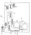
図1は、本発明の実施例に係る画像記録装置を示す模式図である。
図1に示す画像記録装置10は、記録媒体(感光材料)Mの両面に画像記録ができる両面画像記録装置である。
この画像記録装置10は、光ビーム走査露光を利用して記録媒体Mを露光記録するものであり、例えば、ロール状に巻き回された長尺状の記録媒体Mから所定の長さだけ引き出されてカットされたカットシート状の記録媒体(以下、シート体ともいう)Mを露光位置(図示せず)に搬送し、プリント画像データ入力部40から供給されたプリント画像データに応じて変調した光ビームを主走査方向に偏向するとともに、主走査方向と直交する副走査方向に記録媒体Mを走査搬送することにより、光ビーム(図示せず)によって記録媒体Mを走査露光して画像を形成するものである。なお、記録媒体Mは、長尺状の基材の表面および裏面の両面に感光層が形成されたものである。FIG. 1 is a schematic diagram illustrating an image recording apparatus according to an embodiment of the present invention.
An
The
画像記録装置10は、供給部12と、裏印字部14と、画像形成部16と、第1濃度測定部18aおよび第2濃度測定部18bと、制御部20と、記録媒体をこれらの間を搬送する搬送手段28とを有する。また、制御部20は、画像記録装置10の全体の動作を制御するものである。これらの第1濃度測定部18aおよび第2濃度測定部18bは、本発明の取得手段を構成するものである。 The
本実施例の画像記録装置10は、プリント画像データ入力部40が接続されており、このプリント画像データ入力部40によりプリント画像データが画像記録装置10に入力される。 The
プリント画像データ入力部40としては、例えば、受付機(図示せず)を用いることができる。この受付機は、プリント店またはコンビニエンスストアの店頭等に設置され、デジタル画像からのプリント作成等の注文を受け付ける装置であり、デジタルカメラ(以下、DSCという)または撮像機能付きの携帯電話等の撮像装置、これらの撮像装置で撮影した画像をデジタル画像として記憶した記録媒体から、画像(デジタル画像)を読み取り、自身が有するモニタに読み取った画像を必要に応じて表示し、かつ各画像のプリント枚数、プリントサイズ、仕上がり指示の情報、および各種の特殊処理等などの注文情報の入力機能を有するものである。受付機に入力されたデジタル画像が所定の通信手段を介して画像記録装置10にプリント画像データとして入力される。 As the print image
受付機においては、注文情報が入力されて注文が確定されると、例えば、受付番号を注文情報に付与するとともに、受付日時も記録する。また、注文情報を照合し、以前に入力された顧客である場合には、予め付与されている顧客IDを付与する。一方、以前に入力された顧客でない場合には、顧客IDを新たに付与する。このように、受付機においては、注文情報に受付番号、受付日時、および顧客IDを付与して、プリント注文されたデジタル画像とともに画像記録装置10に出力する。
さらに、受付機は、メモリカード、CD、MO、またはFDなどのメディアからプリント画像データなどを読み出すためのメディアドライブを備えていても良い。In the accepting machine, when the order information is input and the order is confirmed, for example, a receipt number is given to the order information and the date and time of receipt are recorded. Further, the order information is collated, and if it is a customer input before, a customer ID given in advance is given. On the other hand, if the customer has not been input before, a new customer ID is assigned. As described above, in the reception machine, a reception number, a reception date and time, and a customer ID are added to the order information, and the digital image that has been ordered for printing is output to the
Further, the accepting device may include a media drive for reading print image data from media such as a memory card, CD, MO, or FD.
また、プリント画像データ入力部40としては、ネガフィルムに撮影された被写体の画像、または画像が記録された写真プリントを光電的に読み取り、ネガフィルムまたは写真プリントに記録された画像のデジタル画像データを取得するスキャナを用いることもできる。このスキャナにより得られたデジタル画像データがプリント画像データとして画像記録装置10に出力される。 The print image
スキャナは、例えば、ネガフィルム等に撮影された画像を1コマずつ光電的に読み取る透過光を読み取るスキャナである。このスキャナは、光源と、可変絞りと、画像をR(赤)、G(緑)およびB(青)の三原色に分解するためのR、GおよびBの3枚の色フィルタを有し、回転して任意の色フィルタを光路に作用する色フィルタ板と、フィルムに入射する読取光をフィルムの面方向で均一にする拡散ボックスと、結像レンズユニットと、フィルムの1コマの画像を読み取るエリアセンサであるCCDセンサと、アンプ(増幅器)と、R,GおよびBの各出力信号を、A/D(アナログ/デジタル)変換、Log変換、DCオフセット補正、暗時補正、およびシェーディング補正等を行うデータ処理部を有して構成される。 The scanner is, for example, a scanner that reads transmitted light that photoelectrically reads an image shot on a negative film or the like frame by frame. This scanner has a light source, a variable aperture, and three color filters R, G, and B for separating the image into the three primary colors R (red), G (green), and B (blue). A color filter plate that acts on an optical path of an arbitrary color filter, a diffusion box that makes the reading light incident on the film uniform in the plane direction of the film, an imaging lens unit, and an area for reading an image of one frame of the film CCD sensor, amplifier (amplifier), and R, G and B output signals are subjected to A / D (analog / digital) conversion, log conversion, DC offset correction, dark correction, shading correction, etc. It has a data processing unit to perform.
また、このスキャナは、新写真システム(Advanced Photo System)または135サイズのネガ(あるいはリバーサル)フィルム等のフィルムの種類、サイズ、ストリップス、スライド等のフィルムの形態等に応じて、スキャナの本体に装着自在な専用のキャリアが用意されており、キャリアを交換することにより、各種のフィルム、および処理に対応することができる。フィルムに撮影され、プリント作成に供される画像(コマ)は、このキャリアによって所定の読取位置に搬送、保持される。また、周知のように、新写真システムのフィルムには、磁気記録媒体が形成され、カートリッジIDまたはフィルム種等が記録されており、さらに、撮影時または現像時等に、撮影日時、撮影時のストロボ発光の有無、撮像倍率、撮影シーンID、主要部位置の情報、および現像機の種類等の各種のデータが記録可能である。新写真システムのフィルム(カートリッジ)に対応するキャリアには、この磁気情報の読取手段が配置されており、フィルムを読取位置に搬送する際に磁気情報を読み取り、前記各種の情報が画像処理装置に送られる。 In addition, this scanner can be mounted on the main body of the scanner according to the type of film such as a new photographic system (Advanced Photo System) or 135-size negative (or reversal) film, the size of the film, such as strips and slides. A dedicated carrier that can be mounted is prepared. By exchanging the carrier, various types of films and processing can be handled. An image (frame) photographed on a film and used for print creation is conveyed and held at a predetermined reading position by this carrier. In addition, as is well known, a magnetic recording medium is formed on the film of the new photographic system, and a cartridge ID or film type is recorded. Further, at the time of shooting or development, the shooting date and time, Various data such as the presence / absence of strobe light emission, imaging magnification, shooting scene ID, main part position information, and developing machine type can be recorded. The carrier corresponding to the film (cartridge) of the new photographic system is provided with the magnetic information reading means. When the film is conveyed to the reading position, the magnetic information is read, and the various information is transferred to the image processing apparatus. Sent.
このようなスキャナにおいては、光源から射出され、可変絞りによって光量調整され、色フィルタ板を通過して色調整され、拡散ボックスで拡散された読取光が、キャリアによって所定の読取位置に保持されたフィルムの1コマに入射して、透過することにより、フィルムに撮影されたこのコマの画像を担持する投影光を得る。フィルムの投影光は、結像レンズユニットによってCCDセンサの受光面に結像され、CCDセンサによって光電的に読み取られ、その出力信号がアンプで増幅されて、画像記録装置10に送られる。CCDセンサは、例えば、1380×920画素のエリアCCDセンサが用いられる。 In such a scanner, the reading light emitted from the light source, adjusted in light quantity by the variable aperture, passed through the color filter plate, adjusted in color, and diffused in the diffusion box is held at a predetermined reading position by the carrier. By entering and passing through one frame of the film, projection light carrying an image of this frame photographed on the film is obtained. The projection light of the film is imaged on the light receiving surface of the CCD sensor by the imaging lens unit, read photoelectrically by the CCD sensor, the output signal is amplified by an amplifier, and sent to the
スキャナにおいては、このような画像読取を、色フィルタ板の各色フィルタを順次挿入して3回行うことにより、1コマの画像をR,GおよびBの3原色に分解して読み取る。 In the scanner, such image reading is performed three times by sequentially inserting each color filter on the color filter plate, thereby separating and reading one frame image into three primary colors of R, G, and B.
スキャナは、エリアCCDセンサを用い、色フィルタ板によって読取光を調整することにより、原稿画像(フィルムの投影光)を3原色に分解して画像の読み取りを行っているが、本発明の画像処理装置に画像データを供給するスキャナとしては、R,GおよびBの3原色のそれぞれの読み取りに対応する3つのラインCCDセンサを用い、フィルムをキャリアで走査搬送しつつスリット状の読取光(投影光)によって画像読取を行う、いわゆるスリット走査によって画像を読み取る画像読取装置であってもよい。 The scanner uses an area CCD sensor and adjusts the reading light with a color filter plate to separate the original image (film projection light) into three primary colors and read the image. As a scanner for supplying image data to the apparatus, three line CCD sensors corresponding to reading of the three primary colors of R, G, and B are used, and slit-like reading light (projection light) is scanned and conveyed by a carrier. The image reading apparatus may read an image by so-called slit scanning.
本実施例の画像記録装置10においては、プリント画像データ入力部40として、DSC、PCおよび携帯電話などのデジタル画像の入力手段に限定されるものではなく、撮像機能を含む画像のデジタル画像の取得手段を有し、かつ後述するように通信手段によって画像記録装置10と接続可能なものであれば、各種のものが利用可能である。例えば、デジタルビデオカメラ、またはPDA(Personal Digital Assistance)等である。 In the
DSCは、撮影画像の表示等を行うためのディスプレイを有するものである。PCは、通常のパーソナルコンピュータと同様に、本体、ディスプレイ、マウスおよびキーボード等の操作手段を有するものである。さらに、携帯電話は、撮影機能および撮影画像の表示等を行うためのディスプレイを有するものである。
なお、DSC、PC、および携帯電話はともに、各機器(装置)が有する通常の機能に加え、受付機と同様の注文情報の入力機能を有する。The DSC has a display for displaying captured images and the like. The PC has operation means such as a main body, a display, a mouse, and a keyboard, like a normal personal computer. Furthermore, the mobile phone has a display for performing a photographing function, displaying a photographed image, and the like.
The DSC, PC, and mobile phone all have an order information input function similar to that of the accepting machine in addition to the normal functions of each device (device).
また、受付機、DSC、PC、および携帯電話において、注文情報の入力手段は、キーボード、マウス、タッチパネル、操作キー、操作ボタン、ディスプレイなどを用い、GUI(Graphical User Interface)などを利用する公知の手段で構成すればよい。 Also, in the reception machine, DSC, PC, and mobile phone, the order information input means uses a keyboard, mouse, touch panel, operation keys, operation buttons, display, etc., and uses a GUI (Graphical User Interface) or the like. What is necessary is just to comprise by a means.
本実施例の画像記録装置10において、供給部12は、記録媒体Mを供給するものであり、例えば、ロール状に巻き回された長尺な記録媒体Mが遮光性を有する筐体に収納されたマガジン22a、22bが装填される部位である。
マガジン22a、22bには、通常、記録媒体Mのサイズ(幅)、シルクおよびマット等の感光面の種類、ならびに仕様(厚さおよびベースの種類)等、互いに種類の異なる記録媒体Mが収納される。本実施例では、マガジン22a、22bを2個設けているが、本発明においては、マガジンの数は、特に限定されるものではない。本発明においては、マガジンは、1個でもよく、また、3個以上であってもよい。
また、例えば、マガジン22a、22bのいずれかには、長尺の基材の表面だけに感光層が形成された記録媒体が収納されている。この表面だけに感光層が形成された記録媒体を用いて片面プリントが作製される。In the
Further, for example, in either of the
マガジン22a、22bには、内部に収納された記録媒体Mを引き出して搬送するための引出ローラ対24が設けられている。
また、マガジン22a、22bの出口から所定の長さ離間した位置にカッタ26が設けられている。
引出ローラ対24は、カッタ26で所定の長さのシート体とするためにプリント長さに応じて記録媒体Mを所定の長さだけ引き出した後、引き出しを停止する。The
Further, a
The drawing
カッタ26は、制御部20から送られてきた制御信号に基づいて、各マガジン22a、22bから引き出された記録媒体Mを裁断するものであり、制御部20によりカッタ26の記録媒体Mの切り出し間隔が調整される。このカッタ26により所定長さにカットされたシート体は、裏印字部14に送られる。なお、本実施例においては、供給部12は長尺な記録媒体Mを切断してシート体を供給するものに限定されるものではなく、予め所定の大きさに形成されたシート体を供給するようにしてもよい。また、カッタは各マガジン毎に1ヶずつ配置してもよい。 The
また、各マガジン22a、22bに収納された記録媒体Mの種類を、例えば、バーコードで記録しておき、各マガジン22a、22bが装填される供給部12に読取装置を設け、この読取装置によりバーコードを読み取り、後述する制御部20の記録媒体種情報部62に出力して記録媒体Mの種類を特定できるようにしてもよい。 In addition, the type of the recording medium M stored in each
裏印字部14は、シート体の表面だけに画像を記録する場合、すなわち、片面プリントの場合には、シート体の裏面に写真の撮影日、プリント焼付日、コマ番号、フィルムID番号(符号)、撮影に使用したカメラのID番号、フォトプリンタのID番号等の各種情報、いわゆるバックプリントを制御部20からの制御信号に基づいて、記録(裏印字)するものであり、シート体を搬送する搬送ローラ対と、裏印字ヘッド(図示せず)とを有する。 The
シート体は、ローラおよびローラ対によって上方に搬送されながら、その裏面に裏印字ヘッドによってバックプリントが記録される。裏印字部14としては、インクジェットヘッド、ドットインパクトプリントヘッドまたは熱転写プリントヘッド等公知のプリントヘッドが用いられる。 While the sheet body is conveyed upward by the roller and the roller pair, the back print is recorded on the back surface by the back print head. As the
画像形成部16は、記録媒体Mの表面および裏面の両面に画像を形成(記録)するものである。この画像形成部16は、例えば、記録媒体Mの表面に画像(潜像)を形成する第1像形成部30aと、記録媒体Mの裏面に画像(潜像)を形成する第2像形成部30bと、記録媒体Mの表面および裏面に形成された潜像を現像する現像処理部32とを有する。
第1像形成部30aおよび第2像形成部30bとは、配置位置が異なるだけであり、構成は同じであり、同様の画像記録ができる。このため、第1像形成部30aの構成だけを説明し、第2像形成部30bの構成の説明は省略する。The
The first image forming unit 30a and the second
第1像形成部30aは、例えば、レーザビーム等の光ビームを記録光として用いる公知の光ビーム走査装置である。この光ビーム走査装置は、シート体の赤(R)露光、緑(G)露光および青(B)露光のそれぞれに対応する光ビームを射出する光源、およびこの光源から射出された光ビームを、プリント画像データ入力部40から供給される画像処理後のプリント画像データに応じて変調するAOM(音響光学変調器)等の変調手段、変調された光ビームを、搬送方向と直交する方向(主走査方向)に偏向するポリゴンミラー等の光偏向器、主走査方向に偏向された光ビームを露光位置上の所定位置に所定のビーム径で結像させるfθ(走査)レンズ光路調整用のミラー等を有して構成される。 The first image forming unit 30a is a known light beam scanning device that uses, for example, a light beam such as a laser beam as recording light. The light beam scanning device includes a light source that emits a light beam corresponding to each of red (R) exposure, green (G) exposure, and blue (B) exposure of a sheet, and a light beam emitted from the light source. Modulating means such as an AOM (acousto-optic modulator) that modulates print image data after image processing supplied from the print image
また、PDP(プラズマディスプレイ)アレイ、ELD(エレクトロルミネセントディスプレイ)アレイ、LED(発光ダイオード)アレイ、LCD(液晶ディスプレイ)アレイ、DMD(デジタルマイクロミラーデバイス、登録商標)アレイおよびレーザアレイ等の搬送方向と直交する主走査方向に延在する各種の発光アレイまたは空間変調素子アレイ等を用いるデジタルの露光手段でもよい。
なお、第1像形成部30aの露光位置で行う光ビームの主走査の幅は、シート体の幅に対応するように設定される。第1像形成部30aの上記動作は、制御部20からの制御信号によって制御される。Also, transport directions of PDP (plasma display) array, ELD (electroluminescent display) array, LED (light emitting diode) array, LCD (liquid crystal display) array, DMD (digital micromirror device, registered trademark) array, laser array, etc. Digital exposure means using various light emitting arrays or spatial modulation element arrays extending in the main scanning direction perpendicular to the main scanning direction may be used.
The width of the main scanning of the light beam performed at the exposure position of the first image forming unit 30a is set so as to correspond to the width of the sheet member. The operation of the first image forming unit 30a is controlled by a control signal from the
記録光である光ビームは主走査方向に偏向され、一方、シート体は副走査ローラ対によって搬送されるので、画像データに応じて変調されている光ビームによってシート体は2次元的に走査露光され、画像が記録される。
なお、シート体の搬送方向と直交する主走査方向に走査記録を行うことにより搬送中のシート体に画像を記録する構成であれば、その構成は、特に限定されるものではない。
さらに、光ビームによって2次元的に走査露光されたシート体を搬送する搬出部(図示せず)が設けられている。The light beam, which is recording light, is deflected in the main scanning direction, while the sheet member is conveyed by a pair of sub-scanning rollers, so that the sheet member is scanned and exposed two-dimensionally by the light beam modulated according to the image data. And an image is recorded.
Note that the configuration is not particularly limited as long as an image is recorded on the sheet being conveyed by performing scanning recording in the main scanning direction orthogonal to the sheet conveying direction.
Further, a carry-out unit (not shown) for conveying a sheet body that is two-dimensionally scanned and exposed by the light beam is provided.
第2像形成部30bの下流側に、現像処理部32が設けられている。この現像処理部32は、露光済みの潜像の記録されたシート体(感光材料)に、所定の現像処理および乾燥処理等を施して、シート体をフィルムに撮影された画像が再生された写真プリントとするものである。この現像処理部32は、現像部と、乾燥部とを有する。 A
現像部は、例えば、シート体の搬送方向上流側から順に、シート体を現像する現像槽、および現像された像を定着する定着漂白槽、ならびにシート体を水洗する第1水洗槽、第2水洗槽、第3水洗槽および第4水洗槽が水平方向に並べて設けられている。現像処理されたシート体を乾燥する乾燥部は、第4水洗槽の下流側に設けられている。 The developing unit includes, for example, a developing tank for developing the sheet body, a fixing bleaching tank for fixing the developed image, a first water washing tank for washing the sheet body, and a second water washing in order from the upstream side in the conveyance direction of the sheet body. A tank, a 3rd water washing tank, and a 4th water washing tank are arranged side by side in the horizontal direction. The drying unit for drying the developed sheet body is provided on the downstream side of the fourth water washing tank.
また、現像処理部32においては、現像部の現像槽により現像されて、定着漂白槽により定着されて、第1水洗槽、第2水洗槽、第3水洗槽および第4水洗槽により水洗されて、乾燥部において、例えば、ヒータ(図示せず)および送風機(図示せず)により、乾燥されて写真プリントとなる。 Further, in the
乾燥部には、さらに、搬送部が接続されており、写真プリントが画像記録装置10の外部に搬送される。
現像処理部32の下流側には、写真プリントPの搬送方向と直交する方向、すなわち、写真プリントPの表面Pf側および裏面Pb側にそれぞれ、第1濃度測定部18aおよび第2濃度測定部18bが設けられている。第1濃度測定部18aおよび第2濃度測定部18bは、同じ構成であり、第1濃度測定部18aの構成だけを説明し、第2濃度測定部18bの説明は省略する。The drying unit is further connected with a conveyance unit, and the photographic print is conveyed outside the
On the downstream side of the
第1濃度測定部18aは、画像記録装置10の写真プリントPの出力較正の際に、キャリブレーションチャート(較正チャート)の各パッチの濃度(画像情報)および各パッチの画像形成位置(第1の位置情報)を測定するものであり、本発明において実施するキャリブレーションに応じた公知の濃度計を有する。
また、第1濃度測定部18aは、キャリブレーションチャートの各パッチの濃度を測定するための直交する2方向に移動可能な2次元ステージを有する。キャリブレーションチャートの各パッチの形成位置は、キャリブレーションチャートデータにより特定されている。このため、2次元ステージをキャリブレーションチャートデータに基づいて移動させて、濃度計により各パッチの濃度を測定することにより、各パッチの濃度とともに、各パッチのキャリブレーションチャートにおける画像形成位置も測定される。When the output calibration of the photographic print P of the
The first
第1濃度測定部18aにおける濃度計としては、例えば、R(赤)、G(緑)およびB(青)のそれぞれの光を射出するLED光源を有し、キャリブレーションチャートのグレーパッチの濃度をカラーの3原色の各単色毎に分解して測定し、各単色毎の分解測定結果から、グレーパッチのC(シアン)濃度、M(マゼンタ)濃度およびY(イエロー)濃度を得ることができるとともに、キャリブレーションのカラーパッチの3原色の各単色の濃度を測定し、この測定結果から、各単色毎のC濃度、M濃度およびY濃度を得ることができる濃度計が例示される。また、白色光を射出する白色光源を有し、R、GおよびBのそれぞれの光を透過するフィルタを備え、同様にカラーの3原色の各単色毎に計測し、C濃度、M濃度およびY濃度を得ることができる濃度計を用いても良い。 As the densitometer in the first
第1濃度測定部18aの濃度計は、R光、G光およびB光によってそれぞれC、MおよびY濃度を測定するものに限定されるものではない。例えば、濃度計は、白色光によるグレーパッチの反射輝度を計測して、測定されたグレーの反射輝度から各単色の濃度、すなわちC、MおよびY濃度を算出するようにしても良いし、カラーパッチの各単色毎の反射輝度を測定し、測定された各単色の反射輝度からC、MおよびYの各単色の濃度を算出するようにしても良い。 The densitometer of the first
図2に示すように、制御部20は、プリント画像データ変換部50、両面プリント時補正テーブル52、演算部54、両面プリント時補正LUT56、テーブル変換部58およびチャート生成部60および記録媒体種情報部62を有する。
両面プリント時補正テーブル52およびテーブル変換部58により本発明のプリント画像データ補正部を構成する。As shown in FIG. 2, the
The double-sided printing correction table 52 and the
制御部20において、プリント画像データ変換部50は、画像形成部16、プリント画像データ入力部40、演算部54およびチャート生成部60に接続されている。
両面プリント時補正テーブル52は、画像形成部16、プリント画像データ変換部50およびテーブル変換部58に接続されている。
演算部54は、第1濃度測定部18aおよび第2濃度測定部18b、両面プリント時補正LUT56、チャート生成部60ならびに記録媒体種情報部62に接続されている。
両面プリント時補正LUT56は、テーブル変換部58に接続されている。In the
The double-sided printing correction table 52 is connected to the
The
The double-sided printing correction LUT 56 is connected to the
プリント画像データ変換部50は、プリント画像データ入力部40から入力されたプリント画像データを、写真プリントとして画像形成部16から出力できる出力用画像データに変換するものである。また、プリント画像データ変換部50は、プリント画像データに、画像の色/濃度(調子再現、色再現)および像構造(鮮鋭度、粒状性)等が適正な画像を出力するための基本的な画像処理を施す基本画像処理機能を有するものでもあり、プリント画像データを画質的に完成したものとする。この基本的な画像処理とは、例えば、画像の拡大もしくは縮小(電子変倍処理)、階調補正、色/濃度補正、彩度補正、およびシャープネス処理である。 The print
また、プリント画像データ変換部50は、プリント画像データ入力部40から入力されたプリント画像データにより、出力先を変える機能も有する。例えば、注文情報として片面プリントまたは両面プリントの指定をプリント画像データに付与しておき、この注文情報に基づいて、片面に画像を記録する場合には、画像形成部16に出力し、両面に画像を記録する場合には、両面プリント時補正テーブル52に出力する。 The print image
なお、プリント画像データ変換部50におけるプリント画像データから出力用画像データへの変換は、例えば、LUTが用いられる。また、このLUTは、キャリブレーションの際に演算部54による演算結果に基づいて設定または変更されるものである。
プリント画像データ変換部50のLUTは、記録媒体の表面および裏面のいずれかの面に画像を形成するために用いられるものであり、プリント画像データ変換部50には、表面用LUTおよび裏面用LUTがそれぞれ独立に設けられている。Note that the LUT is used for the conversion from the print image data to the output image data in the print image
The LUT of the print image
また、プリント画像データ変換部50が有する基本画像処理機能は、プリント画像データ入力部40に設けてもよく、画像形成部16に出力する前段で基本画像処理をプリント画像データに施すことができれば、設ける位置は特に限定されるものではない。 The basic image processing function of the print image
両面プリント時補正テーブル52は、両面プリント時において、表面および裏面に形成される各画像によるそれぞれ反対側の面の画像への影響を抑制しつつ、各面における画像が、片面プリント時と同等の品質で適正に再現されるように補正するものである。この両面プリント時補正テーブル52により、両面プリント画像データが補正出力用画像データに変換される。なお、両面プリント時補正テーブル52の作成方法については、後で詳細に説明する。 The double-sided printing correction table 52 suppresses the influence of the images formed on the front and back sides on the images on the opposite side during double-sided printing, while the images on each side are equivalent to those during single-sided printing. The correction is made so that the quality is properly reproduced. This double-sided printing correction table 52 converts double-sided print image data into correction output image data. The method for creating the double-sided printing correction table 52 will be described in detail later.
演算部54は、写真プリントPの画像を適正に再現するために、プリント画像データ変換部50の表面用LUTおよび裏面用LUT、ならびに両面プリント時補正LUT56を作成するものである。プリント画像データ変換部50の表面用LUTおよび裏面用LUT、ならびに両面プリント時補正LUT56の作成方法については後で詳細に説明する。 The
両面プリント時補正LUT56は、記録媒体Mの表面および裏面の両面に画像を記録するとき、表面または裏面に記録された各画像がそれぞれ反対側の面の画像に、例えば、画像の色みの変化および濃度の変化などの影響を与える場合、その影響を抑制し、片面だけに画像を記録して得られる画像と同等の画質となるように補正するためのものである。
この両面プリント時補正LUT56においては、表裏の関係にある複数の色の組み合わせについて、その組み合わせられた色の色みの変化および濃度の変化などの影響を抑制する補正量をテーブルとして有するものである。なお、両面プリント時補正LUT56の作成方法については、後で詳細に説明する。When the double-sided printing correction LUT 56 records an image on both the front and back sides of the recording medium M, each image recorded on the front or back side is changed to an image on the opposite side, for example, a change in color of the image. In the case where an influence such as a change in density is given, the influence is suppressed, and correction is made so that the image quality is equivalent to an image obtained by recording an image on only one side.
This double-sided printing correction LUT 56 has, as a table, a correction amount that suppresses the influence of a change in color and density of the combined color for a combination of a plurality of colors having a front and back relationship. . A method for creating the correction LUT 56 for double-sided printing will be described later in detail.
テーブル変換部58においては、両面プリント画像データの表面側の各画素の画像データと、裏面側の各画素の画像データとについて、それぞれ表裏の関係となる各画素の画素データを組み合わせた表裏の画像データ対と、両面プリント時補正LUT56の各色の組み合わせによる補正量とを対応付ける。そして、表面側の各画素の画像データと、裏面側の各画素の画像データとに対してそれぞれ補正量を算出する。次に、表面側の各画素の画像データと、裏面側の各画素の画像データとに対応する補正テーブルを作成するものである。この補正テーブルが両面プリント時補正テーブル52に出力される。 In the
チャート生成部60は、キャリブレーションチャートを記録するための画像データ(以下、チャートデータという)を記憶しているものであって、キャリブレーションを行う際に、チャートデータをプリント画像データ変換部50および演算部54に供給するものである。 The
チャート生成部60には、表面側または裏面側の片面画像のキャリブレーション、および両面画像のキャリブレーションに用いる少なくとも2種類のキャリブレーションチャートのチャートデータを有する。
なお、本発明においては、キャリブレーションチャートは限定されるものではなく、実施する較正方法に応じたキャリブレーションチャートが、各種利用可能である。例えば、片面画像のキャリブレーションに用いるキャリブレーションチャートとして8段階の階調のグレーまたは単色(C,M,Y)のステップウエッジを用い、C、MおよびYの割合が共に同一のグレーパッチを、等間隔で8階調有するチャートデータ、またはC、MおよびYのパッチが各列ごとに等間隔で8階調有するチャートデータが例示される。The
In the present invention, the calibration chart is not limited, and various calibration charts according to the calibration method to be performed can be used. For example, as a calibration chart used for calibration of a single-sided image, a gray patch having eight gradations of gray or a single color (C, M, Y) step wedge and having the same ratio of C, M, and Y, Examples are chart data having 8 gradations at equal intervals, or chart data having C, M, and Y patches having 8 gradations at equal intervals for each column.
また、両面画像のキャリブレーションに用いる両面用のキャリブレーションチャートは、例えば、記録媒体の表面および裏面に表裏の関係となるパッチが少なくとも色を異ならせて複数形成されたものである。このキャリブレーションチャートは、複数の白黒およびカラーのパッチからなるものであり、表面側および裏面側の全てのパッチにおいて、表面側のパッチと、表面側のパッチに対応する裏面側のパッチとはそれぞれ色が少なくとも異なる。さらに、表面側のパッチと、表面側のパッチに対応する裏面側のパッチとは濃度も異なることが好ましい。 The double-sided calibration chart used for the calibration of the double-sided image is formed by, for example, forming a plurality of patches having different front and back surfaces on the front and back surfaces of the recording medium with different colors. This calibration chart consists of a plurality of black and white and color patches. For all patches on the front side and back side, the front side patch and the back side patch corresponding to the front side patch are respectively The color is at least different. Further, it is preferable that the front side patch and the back side patch corresponding to the front side patch have different densities.
記録媒体種情報部62は、マガジン22a、22bに収納された記録媒体Mについて、透過率および反射率などの記録媒体情報が蓄積されているものである。なお、上述の如く、マガジン22a、22bに収納された記録媒体Mの情報を読み取る読取装置を供給部12に設け、記録媒体種情報部62に入力してもよい。さらには、入力手段により、収納された記録媒体Mの種類などの情報を記録媒体種情報部62に入力してもよい。この記録媒体種情報部62は、記録媒体に応じた記録媒体情報を演算部54に出力する。 The recording medium
演算部54においては、透過率または反射率などの記録媒体情報を補正量の作成パラメータとして用いることにより、濃度測定などが簡素化され、両面プリント時補正LUT56の作成を簡素化できる。さらには、透過率または反射率などの記録媒体情報を補正量の作成パラメータに加えることにより、両面プリント時補正LUT56による色みの変化および濃度の変化の抑制する精度を高くすることができる。
なお、記録媒体種情報部62は、両面プリント時補正LUT56の作成の簡素化、または両面プリント時補正LUT56の作成精度を高くする必要がない場合には、必ずしも設ける必要がない。In the
Note that the recording medium
本実施例の画像記録装置10においては、記録媒体Mの表面および裏面の両面に画像を記録する場合において、両面に形成された各画像がそれぞれ反対側の面の画像に、例えば、色みの変化および濃度の変化など影響を与える場合、その影響を抑制し、片面だけに画像を記録して得られる画像と同等の画像を得るために両面プリント時補正LUT56を設けている。さらに、両面プリント画像データにおける各画素の画像データの各補正量の補正テーブルを作成するテーブル変換部58を設け、この補正テーブルを両面プリント時補正テーブル52に設定することにより、出力用画像データの表面の画像データおよび裏面の画像データに、色および濃度に基づく補正がされる。これにより、色みの変化および濃度の変化など影響が抑制された補正出力用画像データを得ることができる。この補正出力用画像データにより、画像形成部16で、表面および裏面に形成された画像による反対側の面に形成された画像への影響が抑制された写真プリントを得ることができる。この写真プリントは、記録媒体Mの片側だけに画像を形成したものと同等の画質を有するものである。 In the
なお、本実施例においては、画像形成部16について、銀塩方式の画像記録装置を用いたが、本発明は、これに限定されるものではない。例えば、電子写真方式、インクジェット方式、および熱溶融方式など適宜要求される画質、またはプリント形態に応じた画像記録方式のものを適宜用いることができる。 In this embodiment, a silver salt type image recording apparatus is used for the
次に、本実施例の画像記録装置10の制御部20の両面プリント時補正LUT56、テーブル変換部58および両面プリント時補正テーブル52の作成方法(本発明の画像記録装置10の較正方法)について説明する。
本発明の画像記録装置10の較正方法は、記録媒体Mの表面または裏面の片面に画像を記録する場合におけるキャリブレーションが表面および裏面についてなされている状態で行う。Next, a method of creating the double-sided printing correction LUT 56, the
The calibration method of the
先ず、本実施例の画像記録装置10における記録媒体Mの表面または裏面の片面に画像を記録するための表面用LUTおよび裏面用LUTのキャリブレーションについて説明する。
本実施例において、表面用LUTおよび裏面用LUTのキャリブレーションは、公知のキャリブレーション方法により行うことができる。なお、片面に画像を記録する場合におけるキャリブレーションは、表面および裏面のいずれの面においても同じ方法であるため、記録媒体Mの表面に画像を記録する場合について説明する。First, calibration of the front surface LUT and the rear surface LUT for recording an image on one side of the front surface or the back surface of the recording medium M in the
In the present embodiment, calibration of the front surface LUT and the rear surface LUT can be performed by a known calibration method. Note that the calibration in the case of recording an image on one side is the same method for both the front and back surfaces, and therefore the case of recording an image on the front surface of the recording medium M will be described.
先ず、チャート生成部60からチャートデータをプリント画像データ変換部50および演算部54に供給する。このチャートデータに基づいて、第1像形成部30aにより記録媒体Mの表面にパッチが記録される。キャリブレーションチャートのパッチの濃度が第1濃度測定部18aの濃度計により測定される。第1濃度測定部18aの測定結果が演算部54に出力される。そして、チャートデータに基づく各パッチの濃度と、対応する各パッチの測定濃度との差を算出する。この算出された差が許容範囲内であれば、演算部54でLUTを作成することなく、そのままキャリブレーションを終了する。 First, chart data is supplied from the
一方、この算出された差が許容範囲から外れる場合には、記録媒体Mの表面に記録される各パッチの濃度が差が許容範囲となるように、演算部54で補正LUTを新たに作成し、プリント画像データ変換部50の表面用LUTを書き換えるか、または、新規の補正LUTを表面用LUTに設定する。そして、再度、チャート生成部60からチャートデータをプリント画像データ変換部50に出力し、キャリブレーションチャートが形成される。キャリブレーションチャートの各パッチの濃度を第1濃度測定部18aの濃度計により測定し、測定結果が演算部54に出力される。そして、チャートデータに基づく各パッチの濃度と、対応する各パッチの測定濃度との差を算出する。このようにして、算出された差が許容範囲内になるまで繰返し、表面用LUTを書き換えるか、または、新規の補正LUTを表面用LUTに設定をする。 On the other hand, when the calculated difference is out of the allowable range, a correction LUT is newly created by the
裏面のキャリブレーションについても、表面側と同様にして、チャート生成部60からチャートデータをプリント画像データ変換部50および演算部54に供給し、第2像形成部30bにより、キャリブレーションチャートが形成される。キャリブレーションチャートの各パッチの濃度を第1濃度測定部18aの濃度計により測定し、測定結果が演算部54に出力される。そして、チャートデータに基づく各パッチの濃度と、対応する各パッチの測定濃度との差を算出する。算出された差が許容範囲内になるまで繰返し、プリント画像データ変換部50の裏面用LUTを書き換えるか、または、新規の補正LUTを裏面用LUTに設定する。 Also for the back side calibration, the chart data is supplied from the
先ず、チャート生成部60により、両面用のチャートデータをプリント画像データ変換部50および演算部54に出力し、第1像形成部30aおよび第2像形成部30bにより、記録媒体Mの表面および裏面に種々のパッチが記録され、両面用のキャリブレーションチャートを得る。
両面用のキャリブレーションチャートは、複数の白黒およびカラーのパッチを有するものであり、表面側および裏面側の全てのパッチにおいて、表面側のパッチと、この表面側のパッチに対応する裏面側のパッチとはそれぞれ少なくとも色が異なる。なお、画像形成部16はキャリブレーションされているため、各パッチは、色および濃度が許容範囲内の精度で再現されている。First, the
The calibration chart for both sides has a plurality of black and white and color patches. For all patches on the front side and back side, the front side patch and the back side patch corresponding to the front side patch Are at least different in color. Since the
次に、両面用のキャリブレーションチャートの各パッチの濃度、および記録媒体Mにおける画像形成位置(第1の位置情報)を第1濃度測定部18aよび第2濃度測定部18bで測定する。
次に、両面用のチャートデータに基づく各パッチの濃度(画素情報)と、対応する各パッチの測定濃度との差を算出する。
次に、記録媒体Mの表面および裏面のパッチの組み合わせに基づく、測定濃度の差を求める。すなわち、各パッチの色の組み合わせによる各パッチの色みの変化量および濃度の変化量を求める。Next, the density of each patch in the calibration chart for both sides and the image forming position (first position information) on the recording medium M are measured by the first
Next, the difference between the density (pixel information) of each patch based on the chart data for both sides and the measured density of each corresponding patch is calculated.
Next, a difference in measured density based on a combination of front and back patches of the recording medium M is obtained. In other words, the amount of change in color and the amount of change in density of each patch according to the combination of the colors of the patches are obtained.
なお、記録媒体の表裏に各パッチは、チャートデータにおける各パッチの記録媒体Mでの形成位置を示す位置情報(第2の位置情報)により、表裏の対になるものが特定される。また、第1濃度測定部18aよび第2濃度測定部18bによる測定位置が演算部54に測定濃度とともに各パッチの画像形成位置も出力されている。これにより、測定濃度についても各パッチの位置が特定され、表裏の対応付けがされる。このようにして、種々の色の組み合わせによる色みの変化、および濃度の変化量を求め、これらの変化量に基づいて両面プリント時補正LUT56を作成する。 Each patch on the front and back sides of the recording medium is identified as a pair of front and back sides by position information (second position information) indicating the formation position of each patch on the recording medium M in the chart data. In addition, the measurement positions by the first
なお、両面プリント時補正LUT56を2回目以降作成する場合、記録媒体Mの変化、機差、または経時変化などが少ない場合には、キャリブレーションチャートの表面および裏面の各パッチについて測定する必要はなく、キャリブレーションチャートの表面または裏面のいずれかの面の各パッチについて測定し、前回の両面プリント時補正LUT56の作成時に算出した補正量を補間することにより、両面プリント時補正LUT56を作成してもよい。 When the correction LUT 56 for double-sided printing is created for the second and subsequent times, if there are few changes in the recording medium M, machine differences, or changes over time, it is not necessary to measure each patch on the front and back surfaces of the calibration chart. Even if the correction LUT 56 for double-sided printing is created by measuring each patch on either the front surface or the back surface of the calibration chart and interpolating the correction amount calculated at the time of creating the previous correction LUT 56 for double-sided printing, Good.
また、記録媒体Mの変化、機差、または経時変化などが多い場合、またはキャリブレーションを高い精度で実施したい場合には、上述の如く、キャリブレーションチャートの表面および裏面の各パッチについて測定して、キャリブレーションを実施することが好ましい。 Also, when there are many changes in the recording medium M, machine differences, changes over time, etc., or when it is desired to perform calibration with high accuracy, as described above, the patches on the front and back surfaces of the calibration chart are measured. It is preferable to perform calibration.
次に、テーブル変換部58および両面プリント時補正テーブル52の作成方法について説明する。
例えば、図3(a)に示すように、表面の画像70aが16の画素72aからなり、各画素72aがそれぞれ画像データf1〜f16であるとする。また、図3(b)に示すように、裏面の画像70bが16の画素72bからなり、各画素72bがそれぞれ画像データb1〜b16であるとする。このとき、表面側および裏面側のそれぞれ対応する画素の画像データを組み合わせた表裏の画像データ対(f1、b4)、(f2、b3)、・・・、(f16、b13)を作成する。Next, a method of creating the
For example, as shown in FIG. 3 (a), the
次に、画像データ対(f1、b4)、(f2、b3)、・・・、(f16、b13)と、両面プリント時補正LUT56の補正量とを対応付けて、画像データ対(f1、b4)、(f2、b3)、・・・、(f16、b13)における各画像データf1〜f16およびb1〜b16について、それぞれ図3(c)および(d)に示すように補正量d1〜d16およびh1〜h16を算出する。
ここで、補正量d1〜d16は、表面側の各画像ブロック72aの画像データf1〜f16について算出されたものである。また、補正量h1〜h16は、裏面側の各画像ブロック72bの画像データb1〜b16についても算出されたものでもある。Next, the image data pairs (f1 , b4 ), (f2 , b3 ),..., (F16 , b13 ) are associated with the correction amount of the correction LUT 56 for double-sided printing, and the image For each of the image data f1 to f16 and b1 to b16 in the data pairs (f1 , b4 ), (f2 , b3 ),..., (F16 , b13 ), FIG. c) The correction amounts d1 to d16 and h1 to h16 are calculated as shown in (d).
Here, the
次に、表面側の各画像ブロック72aの各補正量d1〜d16、および裏面側の各画像ブロック72bの各補正量h1〜h16を示す補正テーブル(図示せず)を作成する。
次に、各画素72a、72b毎の補正量d1〜d16およびh1〜h16を示す補正テーブルを両面プリント時補正テーブル52に出力し、両面プリント時補正テーブル52を変更する。これにより、画像記録装置10のキャリブレーションが終了する。Next, a correction table showing each
Next, a correction table indicating the correction amounts d1 to d16 and h1 to h16 for each of the
本実施例の画像記録装置10の較正方法においては、出力用画像データの表面の画像データおよび裏面の画像データについて、色みおよび濃度の補正をし、画像の色みの変化および濃度の変化など影響が抑制された補正出力用画像データが得られる両面プリント時補正テーブル52が作成される。 In the calibration method of the
また、本実施例のテーブル変換部58においては、写真プリントPの表面Pfおよび裏面Pbに記録する各画像の重要度に応じて補正量を調整してもよい。例えば、表面Pfの画質を重視する場合には、表面Pfのプリント画像データについて補正量を求め、裏面Pbのプリント画像データについて補正量を求めずに補正テーブルを作成する。このように、テーブル変換部58により、要求される画質に応じて、表面または裏面に形成される画像データに重みを付けて、適宜補正テーブルを設定してもよい。 In the
次に、本実施例の画像記録装置10による両面画像記録方法について説明する。
先ず、プリント画像データ入力部40から、記録媒体Mの両面に画像を記録するための両面プリント画像データをプリント画像データ変換部50およびテーブル変換部58に出力する。Next, a double-sided image recording method by the
First, double-sided print image data for recording images on both sides of the recording medium M is output from the print image
次に、プリント画像データをプリント画像データ変換部50で出力画像用データに変換する。一方、テーブル変換部58において、プリント画像データおよび両面プリント時補正LUT56により、表面側の画像の各画素、および裏面側の画像の各画素における補正テーブルが作成される。この補正テーブルにより、両面プリント時補正テーブル52が設定される。 Next, the print image
次に、両面プリント時補正テーブル52により、出力用画像データに表裏の色みおよび濃度の補正を施す。これにより、表裏の色みの変化および濃度の変化などの影響が排除された補正出力用画像データを得る。次に、この補正出力用画像データを画像形成部16に出力する。 Next, the front and back color and density are corrected for the output image data by the double-sided printing correction table 52. As a result, correction output image data from which influences such as changes in front and back color and density are eliminated are obtained. Next, the correction output image data is output to the
補正出力用画像データに基づいて、画像形成部16により記録媒体Mの両面に画像を記録し、写真プリントPを得る。この写真プリントPは、表面Pfおよび裏面Pbに記録された各画像による反対側の面に形成された画像への影響が抑制されたものであり、記録媒体Mの片側だけ画像を記録して得られた写真プリントと同等の画質を有する。
このように、本実施例の画像記録装置10においては、記録媒体Mの両面に高品質な画像を形成することができ、写真プリントPの表面Pfおよび裏面Pbに記録された画像には、色みの変化および濃度の変化が抑制され、片面にだけ画像が形成された写真プリントと同等の高品質の写真プリントPを得ることができる。Based on the image data for correction output, images are recorded on both sides of the recording medium M by the
Thus, in the
なお、本実施例の画像記録装置10においては、記録媒体Mの表面または裏面の片側だけ画像を記録できることはいうまでもなく、この場合においても、高品質の画像を有する写真プリントが得られる。 In the
以上、本発明の画像記録装置およびその較正方法について詳細に説明したが、本発明は上記実施例に限定はされず、本発明の要旨を逸脱しない範囲において、各種の改良および変更を行ってもよいのはもちろんである。 As described above, the image recording apparatus and the calibration method thereof according to the present invention have been described in detail. However, the present invention is not limited to the above-described embodiments, and various improvements and modifications may be made without departing from the gist of the present invention. Of course it is good.
10 画像記録装置
12 供給部
14 裏印字部
16 画像形成部
18a 第1濃度測定部
18b 第2濃度測定部
20 制御部
40 プリント画像データ入力部
50 プリント画像データ変換部
52 両面プリント時補正テーブル
54 演算部
56 両面プリント時補正LUT
58 テーブル変換部
60 チャート生成部
62 記録媒体種情報部
70a 表面の画像
70b 裏面の画像
72a,72b 画素DESCRIPTION OF
58
Claims (4)
Translated fromJapanese前記画像形成部に、前記記録媒体の表面および裏面に表裏の関係となるパッチが少なくとも色を異ならせて複数形成された較正チャートを少なくとも形成させるチャート生成部と、
前記較正チャートの少なくとも一面に記録された各パッチについて画像情報および記録媒体における形成位置を示す第1の位置情報を取得する取得手段と、
前記取得手段による各パッチの画像情報および前記第1の位置情報と、前記較正チャートの画像データによる前記各パッチの画像情報および前記記録媒体における形成位置を示す第2の位置情報とに基づいて、前記記録媒体の表面および裏面の両面に画像を記録する際の補正量を算出する演算部と、
前記補正量と、前記記録媒体の裏面および表面に記録するプリント画像データの画像情報および前記記録媒体の裏面および表面に記録する画像のプリント画像データの画像情報および前記記録媒体の形成位置情報とに基づいて前記プリント画像データの画像データ補正量を算出し、前記プリント画像データを補正するプリント画像データ補正部とを有し、
前記記録媒体の表面および裏面の両面に画像を形成する場合、前記プリント画像データ補正部により補正されたプリント画像データに基づいて前記画像形成部により、前記記録媒体の表面および裏面にそれぞれ画像が形成されることを特徴とする画像記録装置。An image forming unit that forms an image on at least one of the front surface and the back surface of the recording medium based on the print image data;
A chart generating unit that forms at least a calibration chart in which a plurality of patches having different front and back colors are formed on the front and back surfaces of the recording medium on the image forming unit;
Acquisition means for acquiring image information and first position information indicating a formation position on a recording medium for each patch recorded on at least one surface of the calibration chart;
Based on the image information and the first position information of each patch by the acquisition means, the image information of each patch by the image data of the calibration chart and the second position information indicating the formation position on the recording medium, A calculation unit for calculating a correction amount when recording an image on both the front and back surfaces of the recording medium;
The correction amount, the image information of the print image data recorded on the back surface and the front surface of the recording medium, the image information of the print image data of the image recorded on the back surface and the front surface of the recording medium, and the formation position information of the recording medium An image data correction amount of the print image data is calculated based on the print image data correction unit for correcting the print image data;
When images are formed on both the front and back surfaces of the recording medium, images are formed on the front and back surfaces of the recording medium by the image forming unit based on the print image data corrected by the print image data correcting unit, respectively. An image recording apparatus.
前記記録媒体の表面および裏面の各面に対する画像形成を較正する工程と、
前記記録媒体の表面および裏面に表裏の関係となるパッチが少なくとも色を異ならせて複数形成された較正チャートの少なくとも一面に記録された各パッチの画像情報および第1の位置情報を測定する工程と、
前記測定された各パッチの画像情報および第1の位置情報と、前記較正チャートの画像データによる前記各パッチの画像情報および前記記録媒体における形成位置を示す第2の位置情報とに基づいて、前記記録媒体の表面および裏面に画像を記録する際の補正量を算出する工程とを有することを特徴とする画像記録装置の較正方法。A calibration method for an image recording apparatus capable of recording an image on at least one of a front surface and a back surface of a recording medium based on print image data,
Calibrating image formation for each of the front and back surfaces of the recording medium;
Measuring image information and first position information of each patch recorded on at least one surface of a calibration chart in which a plurality of patches having different front and back colors on the front and back surfaces of the recording medium are formed in different colors; and ,
Based on the measured image information and first position information of each patch, the image information of each patch based on the image data of the calibration chart, and the second position information indicating the formation position on the recording medium, And a step of calculating a correction amount when images are recorded on the front and back surfaces of the recording medium.
Priority Applications (2)
| Application Number | Priority Date | Filing Date | Title |
|---|---|---|---|
| JP2005065300AJP2006247927A (en) | 2005-03-09 | 2005-03-09 | Image recording device, and its calibration method |
| US11/370,972US20060256404A1 (en) | 2005-03-09 | 2006-03-09 | Image recording apparatus and a method of calibrating the same |
Applications Claiming Priority (1)
| Application Number | Priority Date | Filing Date | Title |
|---|---|---|---|
| JP2005065300AJP2006247927A (en) | 2005-03-09 | 2005-03-09 | Image recording device, and its calibration method |
Publications (1)
| Publication Number | Publication Date |
|---|---|
| JP2006247927Atrue JP2006247927A (en) | 2006-09-21 |
Family
ID=37088917
Family Applications (1)
| Application Number | Title | Priority Date | Filing Date |
|---|---|---|---|
| JP2005065300AWithdrawnJP2006247927A (en) | 2005-03-09 | 2005-03-09 | Image recording device, and its calibration method |
Country Status (2)
| Country | Link |
|---|---|
| US (1) | US20060256404A1 (en) |
| JP (1) | JP2006247927A (en) |
Cited By (4)
| Publication number | Priority date | Publication date | Assignee | Title |
|---|---|---|---|---|
| JP2009166389A (en)* | 2008-01-17 | 2009-07-30 | Canon Inc | Calibration data creation method and information processing apparatus |
| JP2009234237A (en)* | 2008-03-28 | 2009-10-15 | Ricoh Co Ltd | Image processing system, image processing apparatus, image processing method and program for executing its method by computer |
| JP2014200922A (en)* | 2013-04-01 | 2014-10-27 | 富士フイルム株式会社 | Image recording device and method |
| CN116097071A (en)* | 2020-08-31 | 2023-05-09 | 惠普发展公司,有限责任合伙企业 | Color Management in Printing |
Families Citing this family (6)
| Publication number | Priority date | Publication date | Assignee | Title |
|---|---|---|---|---|
| JP4431595B2 (en)* | 2007-04-09 | 2010-03-17 | シャープ株式会社 | Image forming apparatus, image forming method, image processing program, and recording medium recording image processing program |
| JP4780055B2 (en)* | 2007-07-30 | 2011-09-28 | 富士ゼロックス株式会社 | Color conversion apparatus and program |
| US8264704B2 (en)* | 2007-08-29 | 2012-09-11 | Xerox Corporation | Method of automatically controlling print quality in digital printing |
| WO2013054560A1 (en)* | 2011-10-12 | 2013-04-18 | 株式会社フオトクラフト社 | Light-reflection/light-transmission image sheet and method for forming light-reflection/light-transmission image sheet |
| JP5990093B2 (en)* | 2012-11-29 | 2016-09-07 | キヤノン株式会社 | Image processing apparatus, image processing method, and program |
| JP7492907B2 (en) | 2020-11-30 | 2024-05-30 | シャープ株式会社 | Printing system, printing device, and method for printing test patterns |
Family Cites Families (2)
| Publication number | Priority date | Publication date | Assignee | Title |
|---|---|---|---|---|
| US5739841A (en)* | 1995-12-28 | 1998-04-14 | Eastman Kodak Company | Apparatus and method for grey level printing with uniformity correction |
| JP2004264749A (en)* | 2003-03-04 | 2004-09-24 | Canon Inc | Image forming apparatus, image processing apparatus, and control method thereof |
- 2005
- 2005-03-09JPJP2005065300Apatent/JP2006247927A/ennot_activeWithdrawn
- 2006
- 2006-03-09USUS11/370,972patent/US20060256404A1/ennot_activeAbandoned
Cited By (4)
| Publication number | Priority date | Publication date | Assignee | Title |
|---|---|---|---|---|
| JP2009166389A (en)* | 2008-01-17 | 2009-07-30 | Canon Inc | Calibration data creation method and information processing apparatus |
| JP2009234237A (en)* | 2008-03-28 | 2009-10-15 | Ricoh Co Ltd | Image processing system, image processing apparatus, image processing method and program for executing its method by computer |
| JP2014200922A (en)* | 2013-04-01 | 2014-10-27 | 富士フイルム株式会社 | Image recording device and method |
| CN116097071A (en)* | 2020-08-31 | 2023-05-09 | 惠普发展公司,有限责任合伙企业 | Color Management in Printing |
Also Published As
| Publication number | Publication date |
|---|---|
| US20060256404A1 (en) | 2006-11-16 |
Similar Documents
| Publication | Publication Date | Title |
|---|---|---|
| US20060256404A1 (en) | Image recording apparatus and a method of calibrating the same | |
| JPH1178112A (en) | Image forming system and image forming method | |
| US6297872B1 (en) | Image forming apparatus | |
| JP3377278B2 (en) | Index print making device | |
| JP3059016B2 (en) | Image reading method | |
| US6496286B1 (en) | Image reader | |
| US6480625B1 (en) | Methods for correcting density characteristic and color | |
| US6864998B2 (en) | Image reading apparatus, image recording medium and image forming apparatus | |
| US20020067494A1 (en) | Image recording apparatus, image recording method, and calibration system of image recording apparatuses | |
| JP2003108987A (en) | Image printer and image printing method | |
| JP3171974B2 (en) | Image reading method | |
| JP4059646B2 (en) | Image recording apparatus, image recording method, and image recording apparatus calibration system | |
| US6559923B2 (en) | Image reproducing apparatus which performs the same processing on image data to be displayed as image data to be printed | |
| JP4377938B2 (en) | Image processing method and image processing apparatus | |
| JPH11258712A (en) | Setup method of printer and photograph printing device, print system and photograph printing system and setup system for printer and photograph printing device | |
| JP2000059637A (en) | Color correction device and image reader | |
| JP2004050610A (en) | Image recorder and its adjusting method | |
| JPH11314406A (en) | Image recorder, manufacture and adjusting method therefor | |
| JP2004299112A (en) | Image formation device and image formation method | |
| JP3653648B2 (en) | Image recording device | |
| JP2008203424A (en) | Output gradation value-density relationship correction method and module for implementing this method | |
| JP2004299113A (en) | Image formation device and image formation method | |
| JP4656386B2 (en) | Exposure unit | |
| JP2005064801A (en) | Image forming apparatus | |
| JP2000092326A (en) | Density characteristic correcting method and color correcting method |
Legal Events
| Date | Code | Title | Description |
|---|---|---|---|
| A711 | Notification of change in applicant | Free format text:JAPANESE INTERMEDIATE CODE: A712 Effective date:20061215 | |
| A300 | Application deemed to be withdrawn because no request for examination was validly filed | Free format text:JAPANESE INTERMEDIATE CODE: A300 Effective date:20080513 |