JP2006247392A - Lens for ultrasonic phacoemulsification - Google Patents
Lens for ultrasonic phacoemulsificationDownload PDFInfo
- Publication number
- JP2006247392A JP2006247392AJP2006060801AJP2006060801AJP2006247392AJP 2006247392 AJP2006247392 AJP 2006247392AJP 2006060801 AJP2006060801 AJP 2006060801AJP 2006060801 AJP2006060801 AJP 2006060801AJP 2006247392 AJP2006247392 AJP 2006247392A
- Authority
- JP
- Japan
- Prior art keywords
- tip
- phacoemulsification
- pat
- cutting
- lens
- Prior art date
- Legal status (The legal status is an assumption and is not a legal conclusion. Google has not performed a legal analysis and makes no representation as to the accuracy of the status listed.)
- Granted
Links
Images
Classifications
- A—HUMAN NECESSITIES
- A61—MEDICAL OR VETERINARY SCIENCE; HYGIENE
- A61F—FILTERS IMPLANTABLE INTO BLOOD VESSELS; PROSTHESES; DEVICES PROVIDING PATENCY TO, OR PREVENTING COLLAPSING OF, TUBULAR STRUCTURES OF THE BODY, e.g. STENTS; ORTHOPAEDIC, NURSING OR CONTRACEPTIVE DEVICES; FOMENTATION; TREATMENT OR PROTECTION OF EYES OR EARS; BANDAGES, DRESSINGS OR ABSORBENT PADS; FIRST-AID KITS
- A61F9/00—Methods or devices for treatment of the eyes; Devices for putting in contact-lenses; Devices to correct squinting; Apparatus to guide the blind; Protective devices for the eyes, carried on the body or in the hand
- A61F9/007—Methods or devices for eye surgery
- A61F9/00736—Instruments for removal of intra-ocular material or intra-ocular injection, e.g. cataract instruments
- A61F9/00745—Instruments for removal of intra-ocular material or intra-ocular injection, e.g. cataract instruments using mechanical vibrations, e.g. ultrasonic
- A—HUMAN NECESSITIES
- A61—MEDICAL OR VETERINARY SCIENCE; HYGIENE
- A61B—DIAGNOSIS; SURGERY; IDENTIFICATION
- A61B17/00—Surgical instruments, devices or methods
- A61B17/32—Surgical cutting instruments
- A61B17/320068—Surgical cutting instruments using mechanical vibrations, e.g. ultrasonic
- A61B2017/320098—Surgical cutting instruments using mechanical vibrations, e.g. ultrasonic with transverse or torsional motion
Landscapes
- Health & Medical Sciences (AREA)
- Ophthalmology & Optometry (AREA)
- General Health & Medical Sciences (AREA)
- Public Health (AREA)
- Engineering & Computer Science (AREA)
- Biomedical Technology (AREA)
- Heart & Thoracic Surgery (AREA)
- Vascular Medicine (AREA)
- Life Sciences & Earth Sciences (AREA)
- Animal Behavior & Ethology (AREA)
- Nuclear Medicine, Radiotherapy & Molecular Imaging (AREA)
- Surgery (AREA)
- Veterinary Medicine (AREA)
- Surgical Instruments (AREA)
- Dental Tools And Instruments Or Auxiliary Dental Instruments (AREA)
- Lubricants (AREA)
- Glass Compositions (AREA)
- Pharmaceuticals Containing Other Organic And Inorganic Compounds (AREA)
- Laser Surgery Devices (AREA)
- Semiconductor Lasers (AREA)
- Medical Preparation Storing Or Oral Administration Devices (AREA)
- Pens And Brushes (AREA)
Abstract
Translated fromJapaneseDescription
Translated fromJapanese本発明は、一般的に、水晶体超音波乳化吸引術分野に関し、より詳細には、ねじり振動式水晶体超音波乳化吸引術のカッティングチップ(cutting tip)に関する。 The present invention generally relates to the field of phacoemulsification and, more particularly, to a cutting tip for torsional vibration phacoemulsification.
最も簡単に言えば人間の目は、角膜と呼ばれる透明な外側部を通して光が伝わって視力を提供するように機能し、網膜上の水晶体を通して結像するように機能する。結像の質は、目の大きさと形、そして角膜と水晶体の透明度を含んだ多くの要因によっている。 In simplest terms, the human eye functions to provide visual acuity through light transmitted through a transparent outer part called the cornea, and functions to image through a lens on the retina. The quality of the imaging depends on many factors, including the size and shape of the eye and the transparency of the cornea and lens.
年齢と病気が水晶体の透明度の低下を引き起こすときは、網膜に伝えることができる光の減少により、視力が悪化する。この目の水晶体内の欠陥は、医学上、白内障として知られている。この病気の受け入れられている治療は、水晶体の外科的な除去と人工の眼内レンズ(IOL)によるレンズ機能の交換である。 When age and illness cause a loss of transparency in the lens, vision decreases due to a decrease in light that can be transmitted to the retina. This defect in the lens of the eye is medically known as a cataract. The accepted treatment for this disease is surgical removal of the lens and replacement of lens function with an artificial intraocular lens (IOL).
米国においては、白内障水晶体の大部分は、水晶体超音波乳化吸引術という外科技術により取り除かれる。この処置の間には、薄い水晶体超音波乳化吸引術用のカッティングチップが、病気の水晶体の中に入れられて、超音波によって振動される。振動するカッティングチップは、水晶体が目の外に吸引されることができるように、水晶体を液化または乳化する。病気の水晶体が取り除かれると、人工のレンズに置き換えられる。 In the United States, most of the cataractous lens is removed by a surgical technique called phacoemulsification. During this procedure, a thin phacoemulsification cutting tip is placed in the diseased lens and vibrated ultrasonically. The vibrating cutting tip liquefies or emulsifies the lens so that the lens can be sucked out of the eye. When the sick lens is removed, it is replaced with an artificial lens.
目の処置に適している典型的な超音波外科装置は、超音波で駆動されるハンドピースと、付属カッティングチップと、洗浄スリーブと、電気制御装置とから成る。ハンドピースアセンブリは、電気ケーブルとフレキシブルチューブによって制御装置に接続される。電気ケーブルを通して、制御装置は、ハンドピースによって付属カッティングチップへ伝達される電力レベルを変え、フレキシブルチューブは、ハンドピースアセンブリを通して目に洗浄流体を供給して、目から吸引流体を汲み出す。 A typical ultrasonic surgical device suitable for eye treatment consists of an ultrasonically driven handpiece, an attached cutting tip, an irrigation sleeve, and an electrical control device. The handpiece assembly is connected to the control device by an electrical cable and a flexible tube. Through the electrical cable, the controller changes the power level transmitted by the handpiece to the attached cutting tip, and the flexible tube supplies cleaning fluid to the eye through the handpiece assembly and pumps suction fluid out of the eye.
ハンドピースの作動部分は、中心に位置した、圧電性結晶一式に直接取付けられている中空の共鳴バーまたはホーンである。その結晶は、水晶体超音波乳化吸引術中に、ホーンと付属カッティングチップ両方の駆動に必要な要求される超音波振動を供給すると共に、制御装置によって制御される。結晶/ホーンのアセンブリは弾力性のある土台によって、ハンドピースの中空本体や中空殻の中に吊るされている。ハンドピース本体は、本体の末端部において小径部分や円錐体で終わっている。円錐体は洗浄スリーブを受け入れるように、外側にねじが切られている。同様にホーンの穴はカッティングチップの外側のねじ部を受け入れるようにその末端部の内側にねじが切られている。洗浄スリーブはまた、円錐体外側のねじ部上で、ねじで留めることができる内側をねじ切りされた穴を有している。カッティングチップは、洗浄スリーブの開口端を予め定めた量だけすぎて先端が突出するように調整される。超音波ハンドピースとカッティングチップは特許文献1〜12において更に十分に説明されている。 The working part of the handpiece is a hollow, resonant bar or horn located directly in the center and attached directly to the set of piezoelectric crystals. The crystal supplies the required ultrasonic vibrations required to drive both the horn and the attached cutting tip during the phacoemulsification and aspiration, and is controlled by the controller. The crystal / horn assembly is suspended in the hollow body or hollow shell of the handpiece by a resilient foundation. The handpiece body ends with a small diameter portion or cone at the distal end of the body. The cone is externally threaded to accept the cleaning sleeve. Similarly, the horn hole is threaded inside its distal end to accept the threaded portion outside the cutting tip. The cleaning sleeve also has an internally threaded hole that can be screwed onto the threaded portion outside the cone. The cutting tip is adjusted such that the tip protrudes past the opening end of the cleaning sleeve by a predetermined amount. Ultrasonic handpieces and cutting tips are more fully described in US Pat.
使用にあたり、カッティングチップと洗浄スリーブの端部は、角膜、強膜または他の位置にある予め定められた幅の小さな切り口の中に挿入される。カッティングチップは結晶駆動の超音波ホーンにより洗浄スリーブの中で、その縦軸方向に沿って超音波振動され、その結果、原位置で選択された組織を乳化する。カッティングチップの中空穴は、ホーンの中の穴と通じていて、順に、ハンドピースから制御装置へ向かう吸引配管に通じている。制御装置の減圧または真空装置は、カッティングチップの開口端、カッティングチップ、ホーンの穴そして吸引線を通して、目から乳化された組織を収集装置の中にくみ出す、または吸引する。乳化された組織の吸引は、洗浄スリーブの内表面とカッティングチップの間にある小さな環状の隙間を通して手術部位に注入される生理食塩水の洗浄溶液や洗浄流体により補助される。 In use, the cutting tip and the end of the cleaning sleeve are inserted into a small, predetermined cut in the cornea, sclera or other location. The cutting tip is ultrasonically vibrated along the longitudinal direction in the cleaning sleeve by a crystal driven ultrasonic horn, thereby emulsifying the tissue selected in situ. The hollow hole of the cutting tip communicates with the hole in the horn, and in turn leads to a suction pipe from the handpiece to the control device. The vacuum or vacuum device of the controller pumps or aspirates the emulsified tissue from the eye into the collection device through the open end of the cutting tip, the cutting tip, the horn hole and the suction line. The suction of the emulsified tissue is assisted by a saline cleaning solution or fluid that is injected into the surgical site through a small annular gap between the inner surface of the cleaning sleeve and the cutting tip.
広く受け入れられている水晶体超音波乳化吸引術用のチップの一つは、鐘のようにふくれた、または、口が広がった末端部を有している。そのようなチップは、特許文献13(パリシ(Parisi))で説明されている。そのようなデザインは、チップのシャフト部の穴を小さく保持したまま、チップに真空が加えられるときに保持力の増大のみならず、より大きな水晶体構成要素の取得を可能にさせる。この特徴の組み合わせは、末端部が塞がれて、この閉鎖が開放されるときに、前房(anterior chamber)からの突然の流出を低減することによって、前房の安定性を増加する。 One widely accepted tip for phacoemulsification has a belly-shaped blister or a widened end. Such a chip is described in US Pat. Such a design allows acquisition of larger lens components as well as increased holding force when a vacuum is applied to the chip while keeping the hole in the shaft portion of the chip small. This combination of features increases the stability of the anterior chamber by reducing sudden outflow from the anterior chamber when the distal end is blocked and the closure is opened.
もう一つの水晶体超音波乳化吸引術用のチップは、口が広がった末端部を伴う、または伴わない、傾斜した、または”湾曲した”チップである。これらのチップは、特許文献14(マッコール(Mackool))、特許文献15(イモンティ(Imonti))、そして特許文献16(ケルマン(Kelman))で説明されている。これらのチップは、所定の角度で曲がっている、シャフトから遠く離れた末端部分を伴う、大部分が直線的なシャフトを有する。湾曲したチップは、非常に多くの外科医によって使用され、特許文献17(アニスら(Anis))及び特許文献18(チョン(Chon))で説明されるような、そしてテキサス州のフォートワースにあるアルコン研究所から市販されているNeoSoniX(登録商標)のような、振動する水晶体超音波乳化術用のハンドピースとつないで、使用されるときに特に有益であるが、チップの湾曲位置がチップのスリーブ部分に近接しているために、チップのスリーブ部分から、外挿法(extrapolation)により、近接したカッティングエッジ(cutting edge)の位置を判断するのは難しいので、外科医の中にはこの湾曲したチップを使用したくない者もいる。 Another phacoemulsification tip is a tip that is tilted or “curved” with or without a widened end. These chips are described in U.S. Pat. Nos. 6,099,028 (Mackool), U.S. Pat. These tips have a largely straight shaft with a distal end that is bent at a predetermined angle and far from the shaft. Curved tips are used by a great number of surgeons, as described in U.S. Pat. Nos. 5,099,086 (Anis et al. (Anis)) and U.S. Pat. It is especially beneficial when used in conjunction with a vibrating phacoemulsification handpiece, such as NeoSoniX®, which is commercially available from Since it is difficult to determine the position of the cutting edge close to the cutting edge by extrapolation from the sleeve portion of the tip, some surgeons may use this curved tip. Some people do not want to use it.
発明者は、スエージ加工された水晶体超音波乳化吸引術用のチップは、ねじり振動式超音波ハンドピースにとつないで使用されるときに、特に有利になることを発見した。ねじり振動式超音波ハンドピースは、特許文献19(ボークニー(Boukhny))で、更に十分に開示されている。それゆえ、スエージ加工された水晶体超音波乳化吸引術用のチップの必要性が存在し続ける。 The inventor has discovered that a swaged phacoemulsification tip is particularly advantageous when used in conjunction with a torsional vibratory ultrasonic handpiece. A torsional vibratory ultrasonic handpiece is more fully disclosed in US Pat. Therefore, a need continues to exist for a swaged phacoemulsification tip.
本発明は、クリンプした(crimped)またはスエージ加工した(swaged)末端チップを有する水晶体超音波乳化吸引術用のチップを提供することにより、従来技術を改良する。水晶体超音波乳化吸引術用のチップの末端部のスエージ加工は、切断表面領域を増加することによって、チップのねじり振動中に、より効率的な切断を実現する。 The present invention improves on the prior art by providing a tip for phacoemulsification with a crimped or swaged end tip. Swaging the distal end of the tip for phacoemulsification achieves more efficient cutting during torsional vibration of the tip by increasing the cutting surface area.
従って、本発明の一つの目的は、特にねじりの超音波動作中に効率性を増す、水晶体超音波乳化吸引術用のカッティングチップを提供することである。 Accordingly, one object of the present invention is to provide a cutting tip for phacoemulsification and aspiration that increases efficiency, particularly during torsional ultrasonic operation.
本発明のもう一つの目的は、クリンプした、またはスエージ加工した末端チップを有する水晶体超音波乳化吸引術用のカッティングチップを提供することである。 Another object of the present invention is to provide a cutting tip for phacoemulsification with a crimped or swaged end tip.
本発明のこれらの、そして他の有利な点および目的は、以下の詳細な発明、および請求項から明らかになる。 These and other advantages and objects of the invention will be apparent from the following detailed invention and from the claims.
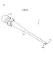
図1から最もよくわかるように、従来技術の水晶体超音波乳化吸引術用のチップ10は、ハブ13から伸長しているシャフト12を有する。シャフト12は、末端チップ14までの間、直線的であるが、末端チップ14は、シャフト12の中心線に対して、傾斜して、または湾曲しても良い。シャフト12は、吸引バイパス穴16を有することができる。 As can best be seen from FIG. 1, a tip 10 for prior art phacoemulsification has a
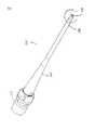
図2から最もよくわかるように、本発明の水晶体超音波乳化吸引術用のチップ110は、ハブ113から伸長するシャフト112を有する。シャフト112は、末端チップ114までの間、直線的である。末端チップ114は、シャフト112の中心線に対して、傾斜して、または湾曲してもよい。シャフト112は吸引バイパス穴116を有してもよい。 As best seen in FIG. 2, the lens
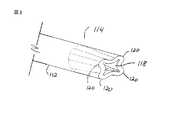
図3から最もよくわかるように、末端チップ114は、吸引ポート118が円形でなく、末端チップが、複数の外部カッティングエッジ120を含むように、クリンプ、またはスエージ加工されている。カッティングエッジ120は、チップ110がねじり、または回転方式で超音波振動されたときに、細胞の切断と吸引を助ける。一方、図3は、4つの溝付きのカッティングエッジ120を示すが、当業者であれば、金属加工技術を使用されることにより、さまざまな形式および様式のカッティングエッジ120が末端チップ114上で形成され得ることを認識するであろう。 As best seen in FIG. 3, the
チップ110は、好ましくは、ステンレススチールまたはチタンから成るが、他の材料を使用しても良い。チップ110は、好ましくは、0.0127m(0.50インチ)から0.0381m(1.50インチ)間、最も好ましくは0.03048(1.20インチ)の全長を有する。チップ110は、従来の金属加工技術を使用して形成され得て、好ましくは、任意のバリを取り除くために電解研磨される。
シャフト112は、0.000127m(0.005インチ)と0.00254m(0.100)インチ間の外径と、0.0000254m(0.001インチ)から0.002286m(0.090インチ)間の内径を有し、略管状である。末端チップ114は、正方形に切断され、または0°と90°間の任意の適切な角度に切断され得る。 The shaft 112 has an outer diameter between 0.000127 m (0.005 inch) and 0.00254 m (0.100) inch and between 0.0000254 m (0.001 inch) and 0.002286 m (0.090 inch). It has an inner diameter and is substantially tubular. The
以上の説明は、図解と説明の目的で提供されている。この分野における当業者にとって、本発明の範囲や精神から逸脱することなしに、上述した発明に変更や修正がなされ得ることは明らかである。 The above description is provided for purposes of illustration and description. It will be apparent to those skilled in the art that changes and modifications may be made to the invention described above without departing from the scope or spirit of the invention.
110 水晶体超音波乳化吸引術用のチップ
112 シャフト
113 ハブ
114 末端チップ
116 吸引バイパス穴
118 吸引ポート
120 カッティングエッジDESCRIPTION OF
Claims (3)
Translated fromJapaneseApplications Claiming Priority (2)
| Application Number | Priority Date | Filing Date | Title |
|---|---|---|---|
| US11/074,739US8403951B2 (en) | 2005-03-08 | 2005-03-08 | Phacoemulsification tip |
| US11/074,739 | 2005-03-08 |
Publications (2)
| Publication Number | Publication Date |
|---|---|
| JP2006247392Atrue JP2006247392A (en) | 2006-09-21 |
| JP4800802B2 JP4800802B2 (en) | 2011-10-26 |
Family
ID=36283737
Family Applications (1)
| Application Number | Title | Priority Date | Filing Date |
|---|---|---|---|
| JP2006060801AActiveJP4800802B2 (en) | 2005-03-08 | 2006-03-07 | Lens for ultrasonic phacoemulsification |
Country Status (11)
| Country | Link |
|---|---|
| US (1) | US8403951B2 (en) |
| EP (1) | EP1700584B1 (en) |
| JP (1) | JP4800802B2 (en) |
| AT (1) | ATE375769T1 (en) |
| AU (1) | AU2006200741B2 (en) |
| BR (1) | BRPI0600774B8 (en) |
| CA (1) | CA2536847C (en) |
| DE (1) | DE602006000163T2 (en) |
| DK (1) | DK1700584T3 (en) |
| ES (1) | ES2296263T3 (en) |
| PT (1) | PT1700584E (en) |
Cited By (2)
| Publication number | Priority date | Publication date | Assignee | Title |
|---|---|---|---|---|
| WO2013125056A1 (en)* | 2012-02-20 | 2013-08-29 | 千寿製薬株式会社 | Fragmentation tip, intraocular surgery device provided with same, method for suppressing occurrence of cavitation, and cataract surgery method |
| US9827142B2 (en) | 2013-05-28 | 2017-11-28 | Jmr Co., Ltd. | Tip for phacoemulsification |
Families Citing this family (28)
| Publication number | Priority date | Publication date | Assignee | Title |
|---|---|---|---|---|
| USD556322S1 (en)* | 2004-10-04 | 2007-11-27 | Ravi Nallakrishnan | Tip of a phacoemulsification needle |
| US20090192440A1 (en)* | 2006-10-13 | 2009-07-30 | Takayuki Akahoshi | Shaped Phacoemulsification Needle Tips |
| US20090099536A1 (en)* | 2006-11-06 | 2009-04-16 | Takayuki Akahoshi Akahoshi | Bidirectional Phacoemulsification Needle Tips for Torsional and Longitudinal Motion |
| CN101401755B (en)* | 2007-09-28 | 2013-01-23 | 株式会社尼德克 | Head for ultrasonic operation and knife head for ultrasonic operation |
| US9402766B2 (en) | 2007-11-01 | 2016-08-02 | Art, Limited | Apparatus and method for phacoemulsification |
| WO2010022460A1 (en)* | 2008-09-01 | 2010-03-04 | Nigel Morlet | Cutting needle tip for surgical instrument |
| US8623040B2 (en) | 2009-07-01 | 2014-01-07 | Alcon Research, Ltd. | Phacoemulsification hook tip |
| EP2552330B1 (en)* | 2010-03-29 | 2015-05-27 | Nigel Morlet | Improved needle tip for surgical instrument |
| US10258505B2 (en) | 2010-09-17 | 2019-04-16 | Alcon Research, Ltd. | Balanced phacoemulsification tip |
| WO2013016772A1 (en) | 2011-08-03 | 2013-02-07 | Nigel Morlet | Grooved needle tip for surgical instrument |
| EP3089639B1 (en) | 2014-01-03 | 2018-07-11 | Koninklijke Douwe Egberts B.V. | Exchangeable supply pack for a beverage dispensing machine, doser, pump assembly and method of manufacturing. |
| CH711082B1 (en)* | 2015-05-15 | 2017-08-15 | Douwe Egberts Bv | Capsule, system for preparing a beverage from such a capsule and use of such a capsule in a beverage preparation device. |
| ES2743219T3 (en) | 2015-05-15 | 2020-02-18 | Douwe Egberts Bv | A capsule, a system for preparing a drinkable beverage from said capsule and use of said capsule in a beverage preparation device |
| DK3134332T3 (en) | 2015-05-15 | 2019-08-26 | Douwe Egberts Bv | COVER, SYSTEM FOR PREPARING A DRINKABLE BEVERAGE FROM SUCH A COVER AND USING SUCH A COVER IN A BEVERAGE COOKING DEVICE |
| EP3566977B2 (en) | 2015-05-15 | 2025-07-09 | Koninklijke Douwe Egberts B.V. | A capsule, a system for preparing a potable beverage from such a capsule and use of such a capsule in a beverage preparation device |
| NL2016781B1 (en) | 2015-05-15 | 2016-12-30 | Douwe Egberts Bv | A capsule, a system for preparing a potable beverage from such a capsule and use of such a capsule in a beverage preparation device |
| AU2016264690A1 (en) | 2015-05-15 | 2017-12-14 | Koninklijke Douwe Egberts B.V. | A capsule, a system for preparing a potable beverage from such a capsule and use of such a capsule in a beverage preparation device |
| DE102015219062A1 (en)* | 2015-10-02 | 2017-04-06 | Geuder Ag | Hollow needle for an ophthalmological instrument |
| AU2016346005B2 (en) | 2015-10-27 | 2022-05-19 | Koninklijke Douwe Egberts B.V. | Capsule, system and method for preparing a beverage |
| NL2016779B1 (en) | 2016-05-13 | 2017-11-16 | Douwe Egberts Bv | A capsule and a system for preparing a potable beverage from such a capsule |
| NL2016780B1 (en) | 2016-05-13 | 2017-11-16 | Douwe Egberts Bv | A capsule, a system for preparing a potable beverage from such a capsule and use of such a capsule in a beverage preparation device |
| JP6998028B2 (en) | 2016-07-27 | 2022-01-18 | 忠彦 小沢 | Crushing tips for eye surgery |
| NL2017587B1 (en) | 2016-10-07 | 2018-04-16 | Douwe Egberts Bv | Capsule, system and method for preparing a beverage |
| NL2019254B9 (en) | 2016-10-07 | 2018-09-10 | Douwe Egberts Bv | A capsule, a system for preparing a potable beverage from such a capsule and use of such a capsule in a beverage preparation device |
| NL2019253B1 (en) | 2017-07-14 | 2019-01-28 | Douwe Egberts Bv | Assembly of a capsule and a brew chamber, brew chamber, beverage preparation machine, capsule and use of a capsule. |
| US11116890B2 (en)* | 2017-08-28 | 2021-09-14 | Surgical Design Corporation | Ocular work tip sleeve adapter |
| US11419971B2 (en)* | 2017-08-28 | 2022-08-23 | Surgical Design Corporation | Ocular surgical work tip adapter |
| US11166845B2 (en) | 2018-04-03 | 2021-11-09 | Alcon Inc. | Ultrasonic vitreous cutting tip |
Citations (8)
| Publication number | Priority date | Publication date | Assignee | Title |
|---|---|---|---|---|
| US4869715A (en)* | 1988-04-21 | 1989-09-26 | Sherburne Fred S | Ultrasonic cone and method of construction |
| DE19651676A1 (en)* | 1995-12-22 | 1997-06-26 | Ruck & Partner Gmbh | Hollow needle for instrument for destroying eye lens and for sucking up emulsion of infusion fluid and lens residue |
| JPH10127682A (en)* | 1996-10-31 | 1998-05-19 | Nidek Co Ltd | Ultrasonic operation device |
| US6165150A (en)* | 1997-12-29 | 2000-12-26 | Surgical Design Corporation | Tips for ultrasonic handpiece |
| US20020099400A1 (en)* | 2001-01-22 | 2002-07-25 | Wolf John R. | Cataract removal apparatus |
| JP2003052712A (en)* | 2001-08-09 | 2003-02-25 | Olympus Optical Co Ltd | Ultrasonic treatment device for surgical operation |
| JP2004525719A (en)* | 2001-04-19 | 2004-08-26 | シナージェティックス インコーポレイテッド | High performance ultrasonic surgical suction tip |
| JP2004305682A (en)* | 2003-04-09 | 2004-11-04 | Akira Shibata | Plate-like ultrasonic wave chip for cataract surgery device for phacoemulsification and aspiration |
Family Cites Families (27)
| Publication number | Priority date | Publication date | Assignee | Title |
|---|---|---|---|---|
| NL145136C (en)* | 1967-07-25 | 1900-01-01 | ||
| US4223676A (en)* | 1977-12-19 | 1980-09-23 | Cavitron Corporation | Ultrasonic aspirator |
| US4246902A (en)* | 1978-03-10 | 1981-01-27 | Miguel Martinez | Surgical cutting instrument |
| US4493694A (en)* | 1980-10-17 | 1985-01-15 | Cooper Lasersonics, Inc. | Surgical pre-aspirator |
| US4445509A (en)* | 1982-02-04 | 1984-05-01 | Auth David C | Method and apparatus for removal of enclosed abnormal deposits |
| US4515583A (en)* | 1983-10-17 | 1985-05-07 | Coopervision, Inc. | Operative elliptical probe for ultrasonic surgical instrument and method of its use |
| US4609368A (en)* | 1984-08-22 | 1986-09-02 | Dotson Robert S Jun | Pneumatic ultrasonic surgical handpiece |
| US4589415A (en)* | 1984-08-31 | 1986-05-20 | Haaga John R | Method and system for fragmenting kidney stones |
| US4816018A (en)* | 1985-08-02 | 1989-03-28 | Ultramed Corporation | Ultrasonic probe tip |
| US4922902A (en)* | 1986-05-19 | 1990-05-08 | Valleylab, Inc. | Method for removing cellular material with endoscopic ultrasonic aspirator |
| US4989583A (en)* | 1988-10-21 | 1991-02-05 | Nestle S.A. | Ultrasonic cutting tip assembly |
| US5154694A (en)* | 1989-06-06 | 1992-10-13 | Kelman Charles D | Tissue scraper device for medical use |
| US5911699A (en)* | 1990-07-17 | 1999-06-15 | Aziz Yehia Anis | Removal of tissue |
| US5282847A (en)* | 1991-02-28 | 1994-02-01 | Medtronic, Inc. | Prosthetic vascular grafts with a pleated structure |
| US5653724A (en)* | 1993-08-18 | 1997-08-05 | Imonti; Maurice M. | Angled phacoemulsifier tip |
| US5733297A (en)* | 1996-09-10 | 1998-03-31 | Medical Instrument Development Laboratories, Inc. | Cutter for surgical probe |
| US6126629A (en)* | 1997-12-18 | 2000-10-03 | Bausch & Lomb Surgical, Inc. | Multiple port phaco needle |
| US6039715A (en)* | 1998-05-11 | 2000-03-21 | Mackool; Richard J. | Angulated phacoemulsification needle whose outer surface converges and inner channel narrows |
| US6196989B1 (en)* | 1998-06-04 | 2001-03-06 | Alcon Laboratories, Inc. | Tip for liquefracture handpiece |
| US6676628B2 (en) | 1998-06-04 | 2004-01-13 | Alcon Manufacturing, Ltd. | Pumping chamber for a liquefracture handpiece |
| US6398759B1 (en)* | 1998-06-04 | 2002-06-04 | Alcon Manufacturing, Ltd. | Liquefracture handpiece tip |
| US6077285A (en)* | 1998-06-29 | 2000-06-20 | Alcon Laboratories, Inc. | Torsional ultrasound handpiece |
| US6256859B1 (en)* | 1998-09-25 | 2001-07-10 | Sherwood Services Ag | Method of manufacturing an aspiring tool |
| US6478766B1 (en)* | 2000-07-25 | 2002-11-12 | Alcon, Inc. | Ultrasound handpiece |
| US7037296B2 (en)* | 2002-04-04 | 2006-05-02 | Advanced Medical Optics, Inc. | Curved multi-purpose phacoemulsification needle |
| US6890308B2 (en)* | 2003-06-03 | 2005-05-10 | Abul Bashar Mohammed Anwarul Islam | Bone marrow biopsy needle |
| US7588553B2 (en)* | 2004-09-07 | 2009-09-15 | Dewey Steven H | Phacoemulsification device having rounded edges |
- 2005
- 2005-03-08USUS11/074,739patent/US8403951B2/enactiveActive
- 2006
- 2006-02-16CACA2536847Apatent/CA2536847C/ennot_activeExpired - Fee Related
- 2006-02-20EPEP06110182Apatent/EP1700584B1/enactiveActive
- 2006-02-20DEDE602006000163Tpatent/DE602006000163T2/enactiveActive
- 2006-02-20ATAT06110182Tpatent/ATE375769T1/enactive
- 2006-02-20ESES06110182Tpatent/ES2296263T3/enactiveActive
- 2006-02-20PTPT06110182Tpatent/PT1700584E/enunknown
- 2006-02-20DKDK06110182Tpatent/DK1700584T3/enactive
- 2006-02-22AUAU2006200741Apatent/AU2006200741B2/ennot_activeCeased
- 2006-03-07JPJP2006060801Apatent/JP4800802B2/enactiveActive
- 2006-03-08BRBRPI0600774Apatent/BRPI0600774B8/ennot_activeIP Right Cessation
Patent Citations (8)
| Publication number | Priority date | Publication date | Assignee | Title |
|---|---|---|---|---|
| US4869715A (en)* | 1988-04-21 | 1989-09-26 | Sherburne Fred S | Ultrasonic cone and method of construction |
| DE19651676A1 (en)* | 1995-12-22 | 1997-06-26 | Ruck & Partner Gmbh | Hollow needle for instrument for destroying eye lens and for sucking up emulsion of infusion fluid and lens residue |
| JPH10127682A (en)* | 1996-10-31 | 1998-05-19 | Nidek Co Ltd | Ultrasonic operation device |
| US6165150A (en)* | 1997-12-29 | 2000-12-26 | Surgical Design Corporation | Tips for ultrasonic handpiece |
| US20020099400A1 (en)* | 2001-01-22 | 2002-07-25 | Wolf John R. | Cataract removal apparatus |
| JP2004525719A (en)* | 2001-04-19 | 2004-08-26 | シナージェティックス インコーポレイテッド | High performance ultrasonic surgical suction tip |
| JP2003052712A (en)* | 2001-08-09 | 2003-02-25 | Olympus Optical Co Ltd | Ultrasonic treatment device for surgical operation |
| JP2004305682A (en)* | 2003-04-09 | 2004-11-04 | Akira Shibata | Plate-like ultrasonic wave chip for cataract surgery device for phacoemulsification and aspiration |
Cited By (4)
| Publication number | Priority date | Publication date | Assignee | Title |
|---|---|---|---|---|
| WO2013125056A1 (en)* | 2012-02-20 | 2013-08-29 | 千寿製薬株式会社 | Fragmentation tip, intraocular surgery device provided with same, method for suppressing occurrence of cavitation, and cataract surgery method |
| JPWO2013125056A1 (en)* | 2012-02-20 | 2015-07-30 | 千寿製薬株式会社 | Crushing tip, intraocular surgical device including the same, cavitation generation suppressing method, and cataract operating method |
| US9962289B2 (en) | 2012-02-20 | 2018-05-08 | Senju Pharmaceutical Co., Ltd. | Fragmentation tip, intraocular surgery device provided with same, method for suppressing occurrence of cavitation, and cataract surgery method |
| US9827142B2 (en) | 2013-05-28 | 2017-11-28 | Jmr Co., Ltd. | Tip for phacoemulsification |
Also Published As
| Publication number | Publication date |
|---|---|
| CA2536847A1 (en) | 2006-09-08 |
| ATE375769T1 (en) | 2007-11-15 |
| DK1700584T3 (en) | 2008-02-11 |
| AU2006200741B2 (en) | 2009-11-05 |
| BRPI0600774B1 (en) | 2018-05-15 |
| DE602006000163D1 (en) | 2007-11-29 |
| BRPI0600774A (en) | 2006-11-07 |
| EP1700584B1 (en) | 2007-10-17 |
| PT1700584E (en) | 2008-01-17 |
| JP4800802B2 (en) | 2011-10-26 |
| BRPI0600774B8 (en) | 2021-06-22 |
| US20060217672A1 (en) | 2006-09-28 |
| US8403951B2 (en) | 2013-03-26 |
| ES2296263T3 (en) | 2008-04-16 |
| AU2006200741A1 (en) | 2006-09-28 |
| DE602006000163T2 (en) | 2008-07-24 |
| EP1700584A1 (en) | 2006-09-13 |
| CA2536847C (en) | 2010-12-21 |
Similar Documents
| Publication | Publication Date | Title |
|---|---|---|
| JP4800802B2 (en) | Lens for ultrasonic phacoemulsification | |
| JP4754983B2 (en) | Lens emulsification chip | |
| TWI574663B (en) | Phacoemulsification hook tip | |
| US8308735B2 (en) | Phacoemulsification tip with internal oriented structures | |
| CN102905652A (en) | Phacoemulsification needle with extended tip | |
| JP2006305356A (en) | Low resistance perfusion mechanism and device | |
| WO2006124290A2 (en) | Phacoemulsification tip | |
| WO2006101717A2 (en) | Phacoemulsification tip | |
| JP2008532624A (en) | Lens for ultrasonic phacoemulsification | |
| AU2004277872B2 (en) | Phacoemulsification needle | |
| EP1852096A1 (en) | Phacoemulsification tip | |
| US20060189948A1 (en) | Phacoemulsification tip | |
| JP2019084168A (en) | Ultrasound surgical tip | |
| MXPA06001826A (en) | Phacoemulsification tip |
Legal Events
| Date | Code | Title | Description |
|---|---|---|---|
| A621 | Written request for application examination | Free format text:JAPANESE INTERMEDIATE CODE: A621 Effective date:20080303 | |
| A131 | Notification of reasons for refusal | Free format text:JAPANESE INTERMEDIATE CODE: A131 Effective date:20100713 | |
| A977 | Report on retrieval | Free format text:JAPANESE INTERMEDIATE CODE: A971007 Effective date:20100715 | |
| A521 | Request for written amendment filed | Free format text:JAPANESE INTERMEDIATE CODE: A523 Effective date:20101008 | |
| A131 | Notification of reasons for refusal | Free format text:JAPANESE INTERMEDIATE CODE: A131 Effective date:20110329 | |
| A521 | Request for written amendment filed | Free format text:JAPANESE INTERMEDIATE CODE: A523 Effective date:20110512 | |
| TRDD | Decision of grant or rejection written | ||
| A01 | Written decision to grant a patent or to grant a registration (utility model) | Free format text:JAPANESE INTERMEDIATE CODE: A01 Effective date:20110705 | |
| A01 | Written decision to grant a patent or to grant a registration (utility model) | Free format text:JAPANESE INTERMEDIATE CODE: A01 | |
| A61 | First payment of annual fees (during grant procedure) | Free format text:JAPANESE INTERMEDIATE CODE: A61 Effective date:20110804 | |
| FPAY | Renewal fee payment (event date is renewal date of database) | Free format text:PAYMENT UNTIL: 20140812 Year of fee payment:3 | |
| R150 | Certificate of patent or registration of utility model | Ref document number:4800802 Country of ref document:JP Free format text:JAPANESE INTERMEDIATE CODE: R150 Free format text:JAPANESE INTERMEDIATE CODE: R150 | |
| R250 | Receipt of annual fees | Free format text:JAPANESE INTERMEDIATE CODE: R250 | |
| R250 | Receipt of annual fees | Free format text:JAPANESE INTERMEDIATE CODE: R250 | |
| R250 | Receipt of annual fees | Free format text:JAPANESE INTERMEDIATE CODE: R250 | |
| R250 | Receipt of annual fees | Free format text:JAPANESE INTERMEDIATE CODE: R250 | |
| R250 | Receipt of annual fees | Free format text:JAPANESE INTERMEDIATE CODE: R250 | |
| R250 | Receipt of annual fees | Free format text:JAPANESE INTERMEDIATE CODE: R250 | |
| S111 | Request for change of ownership or part of ownership | Free format text:JAPANESE INTERMEDIATE CODE: R313111 Free format text:JAPANESE INTERMEDIATE CODE: R313113 | |
| S111 | Request for change of ownership or part of ownership | Free format text:JAPANESE INTERMEDIATE CODE: R313111 Free format text:JAPANESE INTERMEDIATE CODE: R313113 | |
| R350 | Written notification of registration of transfer | Free format text:JAPANESE INTERMEDIATE CODE: R350 | |
| R250 | Receipt of annual fees | Free format text:JAPANESE INTERMEDIATE CODE: R250 | |
| R250 | Receipt of annual fees | Free format text:JAPANESE INTERMEDIATE CODE: R250 | |
| R250 | Receipt of annual fees | Free format text:JAPANESE INTERMEDIATE CODE: R250 | |
| R250 | Receipt of annual fees | Free format text:JAPANESE INTERMEDIATE CODE: R250 | |
| R250 | Receipt of annual fees | Free format text:JAPANESE INTERMEDIATE CODE: R250 | |
| R250 | Receipt of annual fees | Free format text:JAPANESE INTERMEDIATE CODE: R250 |