JP2006245802A - Power line carrier communication system, communication device therefor, and power line carrier communication system construction method - Google Patents
Power line carrier communication system, communication device therefor, and power line carrier communication system construction methodDownload PDFInfo
- Publication number
- JP2006245802A JP2006245802AJP2005056239AJP2005056239AJP2006245802AJP 2006245802 AJP2006245802 AJP 2006245802AJP 2005056239 AJP2005056239 AJP 2005056239AJP 2005056239 AJP2005056239 AJP 2005056239AJP 2006245802 AJP2006245802 AJP 2006245802A
- Authority
- JP
- Japan
- Prior art keywords
- communication
- communication device
- power line
- relative position
- line carrier
- Prior art date
- Legal status (The legal status is an assumption and is not a legal conclusion. Google has not performed a legal analysis and makes no representation as to the accuracy of the status listed.)
- Pending
Links
Images


Classifications
- H—ELECTRICITY
- H02—GENERATION; CONVERSION OR DISTRIBUTION OF ELECTRIC POWER
- H02J—CIRCUIT ARRANGEMENTS OR SYSTEMS FOR SUPPLYING OR DISTRIBUTING ELECTRIC POWER; SYSTEMS FOR STORING ELECTRIC ENERGY
- H02J13/00—Circuit arrangements for providing remote indication of network conditions, e.g. an instantaneous record of the open or closed condition of each circuitbreaker in the network; Circuit arrangements for providing remote control of switching means in a power distribution network, e.g. switching in and out of current consumers by using a pulse code signal carried by the network
- H02J13/00002—Circuit arrangements for providing remote indication of network conditions, e.g. an instantaneous record of the open or closed condition of each circuitbreaker in the network; Circuit arrangements for providing remote control of switching means in a power distribution network, e.g. switching in and out of current consumers by using a pulse code signal carried by the network characterised by monitoring
- H—ELECTRICITY
- H02—GENERATION; CONVERSION OR DISTRIBUTION OF ELECTRIC POWER
- H02J—CIRCUIT ARRANGEMENTS OR SYSTEMS FOR SUPPLYING OR DISTRIBUTING ELECTRIC POWER; SYSTEMS FOR STORING ELECTRIC ENERGY
- H02J13/00—Circuit arrangements for providing remote indication of network conditions, e.g. an instantaneous record of the open or closed condition of each circuitbreaker in the network; Circuit arrangements for providing remote control of switching means in a power distribution network, e.g. switching in and out of current consumers by using a pulse code signal carried by the network
- H02J13/00006—Circuit arrangements for providing remote indication of network conditions, e.g. an instantaneous record of the open or closed condition of each circuitbreaker in the network; Circuit arrangements for providing remote control of switching means in a power distribution network, e.g. switching in and out of current consumers by using a pulse code signal carried by the network characterised by information or instructions transport means between the monitoring, controlling or managing units and monitored, controlled or operated power network element or electrical equipment
- H02J13/00016—Circuit arrangements for providing remote indication of network conditions, e.g. an instantaneous record of the open or closed condition of each circuitbreaker in the network; Circuit arrangements for providing remote control of switching means in a power distribution network, e.g. switching in and out of current consumers by using a pulse code signal carried by the network characterised by information or instructions transport means between the monitoring, controlling or managing units and monitored, controlled or operated power network element or electrical equipment using a wired telecommunication network or a data transmission bus
- H—ELECTRICITY
- H02—GENERATION; CONVERSION OR DISTRIBUTION OF ELECTRIC POWER
- H02J—CIRCUIT ARRANGEMENTS OR SYSTEMS FOR SUPPLYING OR DISTRIBUTING ELECTRIC POWER; SYSTEMS FOR STORING ELECTRIC ENERGY
- H02J13/00—Circuit arrangements for providing remote indication of network conditions, e.g. an instantaneous record of the open or closed condition of each circuitbreaker in the network; Circuit arrangements for providing remote control of switching means in a power distribution network, e.g. switching in and out of current consumers by using a pulse code signal carried by the network
- H02J13/00001—Circuit arrangements for providing remote indication of network conditions, e.g. an instantaneous record of the open or closed condition of each circuitbreaker in the network; Circuit arrangements for providing remote control of switching means in a power distribution network, e.g. switching in and out of current consumers by using a pulse code signal carried by the network characterised by the display of information or by user interaction, e.g. supervisory control and data acquisition systems [SCADA] or graphical user interfaces [GUI]
- Y—GENERAL TAGGING OF NEW TECHNOLOGICAL DEVELOPMENTS; GENERAL TAGGING OF CROSS-SECTIONAL TECHNOLOGIES SPANNING OVER SEVERAL SECTIONS OF THE IPC; TECHNICAL SUBJECTS COVERED BY FORMER USPC CROSS-REFERENCE ART COLLECTIONS [XRACs] AND DIGESTS
- Y02—TECHNOLOGIES OR APPLICATIONS FOR MITIGATION OR ADAPTATION AGAINST CLIMATE CHANGE
- Y02E—REDUCTION OF GREENHOUSE GAS [GHG] EMISSIONS, RELATED TO ENERGY GENERATION, TRANSMISSION OR DISTRIBUTION
- Y02E60/00—Enabling technologies; Technologies with a potential or indirect contribution to GHG emissions mitigation
- Y—GENERAL TAGGING OF NEW TECHNOLOGICAL DEVELOPMENTS; GENERAL TAGGING OF CROSS-SECTIONAL TECHNOLOGIES SPANNING OVER SEVERAL SECTIONS OF THE IPC; TECHNICAL SUBJECTS COVERED BY FORMER USPC CROSS-REFERENCE ART COLLECTIONS [XRACs] AND DIGESTS
- Y04—INFORMATION OR COMMUNICATION TECHNOLOGIES HAVING AN IMPACT ON OTHER TECHNOLOGY AREAS
- Y04S—SYSTEMS INTEGRATING TECHNOLOGIES RELATED TO POWER NETWORK OPERATION, COMMUNICATION OR INFORMATION TECHNOLOGIES FOR IMPROVING THE ELECTRICAL POWER GENERATION, TRANSMISSION, DISTRIBUTION, MANAGEMENT OR USAGE, i.e. SMART GRIDS
- Y04S10/00—Systems supporting electrical power generation, transmission or distribution
- Y04S10/30—State monitoring, e.g. fault, temperature monitoring, insulator monitoring, corona discharge
- Y—GENERAL TAGGING OF NEW TECHNOLOGICAL DEVELOPMENTS; GENERAL TAGGING OF CROSS-SECTIONAL TECHNOLOGIES SPANNING OVER SEVERAL SECTIONS OF THE IPC; TECHNICAL SUBJECTS COVERED BY FORMER USPC CROSS-REFERENCE ART COLLECTIONS [XRACs] AND DIGESTS
- Y04—INFORMATION OR COMMUNICATION TECHNOLOGIES HAVING AN IMPACT ON OTHER TECHNOLOGY AREAS
- Y04S—SYSTEMS INTEGRATING TECHNOLOGIES RELATED TO POWER NETWORK OPERATION, COMMUNICATION OR INFORMATION TECHNOLOGIES FOR IMPROVING THE ELECTRICAL POWER GENERATION, TRANSMISSION, DISTRIBUTION, MANAGEMENT OR USAGE, i.e. SMART GRIDS
- Y04S10/00—Systems supporting electrical power generation, transmission or distribution
- Y04S10/40—Display of information, e.g. of data or controls
- Y—GENERAL TAGGING OF NEW TECHNOLOGICAL DEVELOPMENTS; GENERAL TAGGING OF CROSS-SECTIONAL TECHNOLOGIES SPANNING OVER SEVERAL SECTIONS OF THE IPC; TECHNICAL SUBJECTS COVERED BY FORMER USPC CROSS-REFERENCE ART COLLECTIONS [XRACs] AND DIGESTS
- Y04—INFORMATION OR COMMUNICATION TECHNOLOGIES HAVING AN IMPACT ON OTHER TECHNOLOGY AREAS
- Y04S—SYSTEMS INTEGRATING TECHNOLOGIES RELATED TO POWER NETWORK OPERATION, COMMUNICATION OR INFORMATION TECHNOLOGIES FOR IMPROVING THE ELECTRICAL POWER GENERATION, TRANSMISSION, DISTRIBUTION, MANAGEMENT OR USAGE, i.e. SMART GRIDS
- Y04S40/00—Systems for electrical power generation, transmission, distribution or end-user application management characterised by the use of communication or information technologies, or communication or information technology specific aspects supporting them
- Y04S40/12—Systems for electrical power generation, transmission, distribution or end-user application management characterised by the use of communication or information technologies, or communication or information technology specific aspects supporting them characterised by data transport means between the monitoring, controlling or managing units and monitored, controlled or operated electrical equipment
- Y04S40/124—Systems for electrical power generation, transmission, distribution or end-user application management characterised by the use of communication or information technologies, or communication or information technology specific aspects supporting them characterised by data transport means between the monitoring, controlling or managing units and monitored, controlled or operated electrical equipment using wired telecommunication networks or data transmission busses
Landscapes
- Engineering & Computer Science (AREA)
- Power Engineering (AREA)
- Computer Networks & Wireless Communication (AREA)
- Cable Transmission Systems, Equalization Of Radio And Reduction Of Echo (AREA)
- Small-Scale Networks (AREA)
Abstract
Translated fromJapaneseDescription
Translated fromJapanese本発明は、電力線を介して通信がなされる通信装置が複数電力線に配置された電力線搬送通信システム及びその通信装置、並びに、電力線に新たな通信装置を配置して電力線搬送通信システムを構築する電力線搬送通信システムの構築方法に関するものである。 The present invention relates to a power line carrier communication system in which communication devices that perform communication via a power line are arranged on a plurality of power lines, a communication device thereof, and a power line for constructing a power line carrier communication system by arranging a new communication device on the power line. The present invention relates to a method for constructing a carrier communication system.
電力線搬送通信システムは、電力線に複数の通信装置を配置し、電力線を介してこれら通信装置間で通信がなされるシステムである。このシステムを構築するにあたっては、システムに配置される通信装置が管理できるよう、その取り付け位置を特定し、管理するようになっている。 A power line carrier communication system is a system in which a plurality of communication devices are arranged on a power line, and communication is performed between these communication devices via the power line. In constructing this system, the mounting position is specified and managed so that the communication devices arranged in the system can be managed.
電力線搬送通信システムでは、通常の信号線による通信のように予め通信が想定された通信線による通信ではなく、電力を供給する電力線を利用して通信がなされるため、通信システムを構成する通信装置は必ずしも所望の位置に設置できるものではなく、その位置を特定するには、通信装置を取り付けた後にその位置を特定する必要がある。 In a power line carrier communication system, communication is performed using a power line that supplies power instead of communication using a communication line that is assumed to be communicated in advance, such as communication using a normal signal line. Is not necessarily installed at a desired position, and in order to specify the position, it is necessary to specify the position after the communication device is attached.
数が少ない場合には、人手により位置を特定する手法も有効であるものの、数が増えたりその取り付け範囲が広範囲に渡るとかなりの負担となることより、最近では、位置特定用装置によりその位置特定を行わせることが希望されている。 If the number is small, the method of specifying the position manually is effective, but since the number increases or the installation range is wide, it becomes a heavy burden. It is hoped that identification will be done.
このような位置特定用装置による従来の位置特定手法としては、電力線に取り付ける通信装置とは別体の位置情報検出装置を用いて通信装置の位置を特定する手法が提案されている。この手法においては、電力線に取り付ける通信装置に無線通信機能を付加しておき、GPS(Global Positioning System)機能と無線通信機能とを有する位置情報検出装置を、電力線に取り付けられた通信装置に近づけ、位置情報検出装置のGPS機能によりその位置を特定する。そして、無線通信機能を利用して、GPS機能により特定された位置情報を位置情報検出装置が通信装置に送信し、通信装置が無線通信機能により受信した位置情報を電力線を介して管理端末に送信するようになっている。(特許文献1) As a conventional position specifying method using such a position specifying device, a method of specifying the position of a communication device using a position information detection device separate from a communication device attached to a power line has been proposed. In this method, a wireless communication function is added to the communication device attached to the power line, and a position information detection device having a GPS (Global Positioning System) function and a wireless communication function is brought closer to the communication device attached to the power line, The position is specified by the GPS function of the position information detection device. Then, using the wireless communication function, the position information detected by the GPS function is transmitted to the communication apparatus by the position information detection apparatus, and the position information received by the communication apparatus by the wireless communication function is transmitted to the management terminal via the power line. It is supposed to be. (Patent Document 1)
上記文献1に記載された手法では、電力線搬送通信システムを構成する通信装置に無線通信機能を付加する必要がある。さらに、この手法では、位置特定用装置を利用はしているものの、人が位置情報検出装置のボタンを押下することでその位置での位置情報を取得し、その位置情報が通信装置に送信されるようになっており、自動的に通信装置の位置を特定することができない。そのため、各通信装置毎に人手により位置情報検出装置を用いて通信装置の位置特定を行う必要があり、通信装置の数が多い場合や、電力線搬送通信システムの領域が広い場合、例えば宅外でシステムが構築されるような場合には、実用的ではないという問題点があった。 In the method described in the above-mentioned document 1, it is necessary to add a wireless communication function to the communication device that constitutes the power line carrier communication system. Further, in this method, although the position specifying device is used, the person acquires the position information at the position by pressing the button of the position information detecting device, and the position information is transmitted to the communication device. Thus, the position of the communication device cannot be specified automatically. Therefore, it is necessary to manually specify the position of the communication device for each communication device by using the position information detection device. When the number of communication devices is large or the area of the power line carrier communication system is wide, for example, outside the house When a system is constructed, there is a problem that it is not practical.
本発明は、上記のような問題点を解決するためになされたものであり、各通信装置の物理的な位置情報を自動的に取得することができる電力線搬送通信システム及びその通信装置、並びに電力線搬送通信システムの構築方法を提供することを目的とするものである。 The present invention has been made to solve the above-described problems, and is a power line carrier communication system capable of automatically acquiring physical position information of each communication device, the communication device thereof, and a power line. An object of the present invention is to provide a method for constructing a carrier communication system.
本発明に係る電力線搬送通信システムは、電力線を介して通信を行う通信装置が電力線に複数配置された電力線搬送通信システムである。そして、この電力線搬送通信システムは、第1の通信装置の物理的な位置に関する情報が格納された記憶部と、第1、第2の通信装置間の通信状態を検出する検出部と、検出部で検出された通信状態に基づき、第1の通信装置と第2の通信装置との相対位置を算出する相対位置算出部と、相対位置算出部で算出された相対位置と記憶部に格納されている第1の通信装置の物理的な位置に関する情報とから第2の通信装置の物理的な位置を算出し、算出された第2の通信装置の物理的な位置に関する情報を記憶部に格納する演算部とを備えている。 The power line carrier communication system according to the present invention is a power line carrier communication system in which a plurality of communication devices that perform communication via a power line are arranged on the power line. The power line carrier communication system includes a storage unit that stores information on the physical position of the first communication device, a detection unit that detects a communication state between the first and second communication devices, and a detection unit. The relative position calculation unit for calculating the relative position between the first communication device and the second communication device based on the communication state detected in step (b), and the relative position calculated by the relative position calculation unit and the storage unit are stored in the storage unit. The physical position of the second communication device is calculated from the information regarding the physical position of the first communication device, and the calculated information regarding the physical position of the second communication device is stored in the storage unit. And an arithmetic unit.
本発明に係る電力線搬送通信システムは、第1の通信装置の物理的な位置に関する情報が格納された記憶部と、第1、第2の通信装置間の通信状態を検出する検出部と、検出部で検出された通信状態に基づき、第1の通信装置と第2の通信装置との相対位置を算出する相対位置算出部と、相対位置算出部で算出された相対位置と記憶部に格納されている第1の通信装置の物理的な位置に関する情報とから第2の通信装置の物理的な位置を算出し、算出された第2の通信装置の物理的な位置に関する情報を記憶部に格納する演算部とを備えている。それゆえ、通信装置が電力線に接続されたとき、その通信装置の物理的な位置を自動的に算出し、通信装置の管理を容易にすることができる。 A power line carrier communication system according to the present invention includes a storage unit that stores information related to a physical position of a first communication device, a detection unit that detects a communication state between the first and second communication devices, and a detection The relative position calculation unit that calculates the relative position between the first communication device and the second communication device based on the communication state detected by the unit, the relative position calculated by the relative position calculation unit, and the storage unit are stored. The physical position of the second communication device is calculated from the information regarding the physical position of the first communication device, and the calculated information regarding the physical position of the second communication device is stored in the storage unit. And an arithmetic unit for performing. Therefore, when the communication device is connected to the power line, the physical position of the communication device can be automatically calculated to facilitate the management of the communication device.
以下で、この発明の実施の形態を図面に基づいて説明する。 Hereinafter, embodiments of the present invention will be described with reference to the drawings.
実施の形態1.
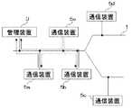
図1はこの実施の形態1の電力線搬送通信システムの構成を示す図である。図1に示すように、電力を供給する電力線1には管理装置3及び複数の通信装置5が配置され、電力線1を介してこれら複数の通信装置間で通信がなされるようになっている。Embodiment 1 FIG.
FIG. 1 is a diagram showing the configuration of the power line carrier communication system of the first embodiment. As shown in FIG. 1, a management device 3 and a plurality of
尚、ここでは、管理用の管理装置3を設けるようにしているが、所定の通信装置に管理機能を付加し、特に専用の管理装置を用いないようにしてもよい。 Although the management device 3 for management is provided here, a management function may be added to a predetermined communication device, and a special management device may not be used.
図2は図1に示した管理装置3の構造を示すブロック図である。図2に示すように、管理装置3は、電力線1を介して通信を行うための電力線搬送通信部31と、演算部32と、電力線1の物理的な経路に関する電力線物理経路情報を保持するデータベース33と、通信装置5(管理装置3も含む)の物理的な位置に関する通信装置物理位置情報を保持するデータベース34とを有している。ここで、物理的な位置とは、相対的な位置ではなく、絶対的な位置を意味するものである。 FIG. 2 is a block diagram showing the structure of the management apparatus 3 shown in FIG. As illustrated in FIG. 2, the management device 3 includes a power line
演算部32は、通信装置5と通信して通信状態を取得するための通信装置通信状態取得部35と、通信状態取得部35、記憶部(データベース33、34)に各々格納されている電力線物理経路情報及び通信装置物理位置情報を用いて通信装置5の物理的な位置を算出する通信装置物理位置算出部36を有している。 The
このような第1の通信装置としての管理装置3では、第2の通信装置5からの通信状態を通信装置通信状態取得部35で検出する。そして、位置算出部36における相対位置算出部で、この通信状態に基づいて第2の通信装置5と管理装置3との相対的な位置を求め、相対位置算出部で算出された結果とデータベース34に格納されている管理装置3の位置に関する情報とから第2の通信装置5の位置を特定するようになっている。 In the management device 3 as the first communication device, the communication device communication
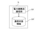
図3は図1に示した通信装置5の構造を示すブロック図である。図3に示すように、通信装置5は、電力線1を介して通信を行うための電力線搬送通信部51と、通信状態を保持するための通信状態保持部52とを有している。
また、この実施の形態1では、新たに通信システムに加えられる新設の通信装置は強度A0の信号を送信するものとする。FIG. 3 is a block diagram showing the structure of the
Further, in this first embodiment, the communication device of the newly added to the new communication system is assumed to transmit a signal strength A0.
図4は図1に示した管理装置3の回路構成を電力線1を含めて示す図である。図4に示すように、管理装置3は、電力線1との接続を行う結合回路41と、結合回路41に接続され結合回路41を介して電力線1に信号の出力又は電力線1から信号を入力するモデム42と、モデム42から取得される情報の制御や演算を行うCPU43と、種々の情報が格納されたメモリ44と、電力線1に接続された電源回路45とから構成されるものである。 FIG. 4 is a diagram showing the circuit configuration of the management device 3 shown in FIG. As shown in FIG. 4, the management device 3 is connected to the power line 1 and the
また、通信装置5は、図4に示した管理装置3における、メモリに格納される情報やCPUで演算される内容が異なるだけであるので、図4に示した構造のものを用いればよい。尚、ここでは一般的な回路構成を示したが、管理装置3、通信装置5を他の構成のもので実現してもよい。 The
次に、動作について説明する。
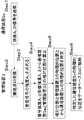
図5は図1に示した通信システムの動作を説明する図である。図6は通信システムの動作を説明するフローチャートである。
図5に示すように、既設の通信装置5として、通信装置5a、5b、5c、5dが配置されており、新たに新設の通信装置5eを通信装置5aと通信装置5bの間に取り付ける場合について説明する。Next, the operation will be described.
FIG. 5 is a diagram for explaining the operation of the communication system shown in FIG. FIG. 6 is a flowchart for explaining the operation of the communication system.
As shown in FIG. 5,
図5、図6に示すように、通信装置5eは、電力線1に接続されると、電力線1に強度A0の信号(搬送波)を出力する(Step1)。出力された搬送波は、電力線1を介して送信され、管理装置3でその搬送波が観測される(Step2)。そして、観測された搬送波の強度A1が通信状態取得部35で取得される(Step3)。As shown in FIGS. 5 and 6, when connected to the power line 1, the
一般に、信号の強度は伝送経路長と共に減衰する。そのため、経路長に対して減衰特性が既知であれば、2点で観測することにより、発信源の場所を特定することが出来る。 In general, the signal strength attenuates with the transmission path length. Therefore, if the attenuation characteristic is known with respect to the path length, the location of the transmission source can be specified by observing at two points.
例えば、経路上を単位距離進む毎に信号の強度がA分の1(aは通常1より大)となるとする。このとき、発生源での信号の大きさをa、発生源から経路長lだけ離れた地点での信号の大きさをf(l,a)とすると、
f(l,a)=a・A−l ・・・(1)
で表される。よって、新設の通信装置5eが強度A0の信号を送信し、管理装置3にて強度A1の信号が受信されたとすると、
A1=A0・A−l ・・・(2)
となる。For example, it is assumed that the signal intensity becomes 1 / A (a is usually larger than 1) every time a unit distance is traveled on the route. At this time, if the magnitude of the signal at the source is a and the magnitude of the signal at a point away from the source by the path length l is f (l, a),
f (l, a) = a · A−l (1)
It is represented by Therefore, the
A 1 = A 0 · A -l ··· (2)
It becomes.
式(2)を変形すると、
l=−logA(A1/A0) ・・・(3)
となり、新設の通信装置5eと管理装置3との相対位置lは、式(3)により求めることができる。ここで、管理装置3の物理的な位置が既知であれば、式(3)で求めた相対位置lとにより、新たに接続された通信装置5eの物理的な位置を求めることができる。When formula (2) is transformed,
l = −logA (A1 / A0 ) (3)
Thus, the relative position 1 between the newly installed
よって、通信装置物理位置算出部36の相対位置算出部において、式(3)を用いて、強度A0、強度A1から通信装置5eと管理装置3との相対位置lを求め(Step4)、通信装置物理位置算出部36において、さらに、データベース34に記憶されている管理装置3の物理的な位置と相対位置lとにより、新たに接続された通信装置5eの物理的な位置を求めるようにする(Step5)。Therefore, the relative position calculation unit of the communication device physical
実際に通信装置5eの物理的な位置を求めるには、単に、管理装置3の物理的な位置と相対位置lとだけで決定するのではなく、データベース33に記憶されている電力線1の物理的な経路に関する情報をも参照して決定するようにすれば、より正確に位置を特定することができる。 In order to actually determine the physical position of the
そして、このようにして求められた通信装置5eの物理的な位置はデータベース34に格納され(Step6)、新たな通信装置の物理位置の特定、あるいは、通信装置5eを管理・制御するために利用される。 The physical position of the
この実施の形態1の電力線搬送通信システムでは、通信装置の物理的な位置を自動的に得ることができ、通信装置の管理を容易に行うことが可能となる。 In the power line carrier communication system of the first embodiment, the physical position of the communication device can be automatically obtained, and the communication device can be easily managed.
この実施の形態1では、管理装置である第1の通信装置と第2の通信装置との信号状態を第1の通信装置で検出するようにしているが、第1の通信装置からの信号を第2の通信装置で検出して通信状態情報保持部52に保持し、この情報を第2の通信装置に送信することで、管理装置が第1、第2の通信装置間の通信状態を取得するようにしていもよい。 In the first embodiment, the first communication device detects the signal state between the first communication device and the second communication device, which are management devices, but the signal from the first communication device is detected. The management device acquires the communication state between the first and second communication devices by detecting the second communication device and holding it in the communication state
また、この実施の形態1では、管理装置で第2の通信装置からの出力信号を受信するようにしているが、隣接する通信装置(あるいは信号を受信可能な任意の通信装置)が第2の通信装置からの出力信号を受信し、その信号を管理装置に送信することで、第2の通信装置と隣接する通信装置との相対位置関係を求め、この隣接する通信装置の絶対位置と求めた相対位置関係とにより第2の通信装置の絶対位置を求めるようにしてもよい。 In the first embodiment, the management device receives the output signal from the second communication device, but the adjacent communication device (or any communication device that can receive the signal) is the second device. By receiving the output signal from the communication device and transmitting the signal to the management device, the relative positional relationship between the second communication device and the adjacent communication device is obtained, and the absolute position of the adjacent communication device is obtained. The absolute position of the second communication device may be obtained based on the relative positional relationship.
また、管理装置が有する位置特定用の機能を各通信装置が有するようにし、管理装置ではない通信装置で新設の通信装置の位置特定を行い、特定された位置に関する情報を管理装置に送信することで管理装置が新設の通信装置の物理的位置を認識するようにしてもよい。 In addition, each communication device has a function for specifying the position of the management device, the position of the new communication device is specified by a communication device that is not the management device, and information on the specified position is transmitted to the management device. Then, the management device may recognize the physical position of the newly installed communication device.
実施の形態2.
実施の形態1では、第1の通信装置だけを用いて位置特定が必要な第2の通信装置の位置を特定するようにしているが、この実施の形態2の電力線搬送通信システムでは、第1の通信装置と第3の通信装置の2つの通信装置を用いて位置特定が必要な第2の通信装置の物理的な位置を特定するものである。Embodiment 2. FIG.
In the first embodiment, the position of the second communication device that needs to be specified is specified using only the first communication device. However, in the power line carrier communication system of the second embodiment, the first The physical position of the second communication device that needs to be specified is specified using two communication devices, i.e., the first communication device and the third communication device.
この実施の形態2の管理装置3は基本的に図2に示した管理装置と同じであるが、この実施の形態2では、図2に示した通信状態取得部35が、隣接する第1の通信装置と位置特定が必要な第2の通信装置間の第1の通信状態と、隣接する第3の通信装置と第2の通信装置間の第2の通信状態を検出するようになっている。そして、位置算出部36が、第1、第2の通信状態に基づき、第2の通信装置と第1及び第3の通信装置との位置関係を算出する相対位置検出部と、算出された相対位置と第1、第3の通信装置の物理位置に関する情報とに基づいて第2の通信装置の物理位置を算出するようになっている。 The management device 3 of the second embodiment is basically the same as the management device shown in FIG. 2, but in this second embodiment, the communication
また、各通信装置の物理的な位置、及び通信装置間の電力線の物理的な経路は既知であり、これらはデータベース33、34に格納されている。尚、その他のシステム構成や通信装置の構成は実施の形態1と同様である。但し、通信装置が送信する信号強度は、既知のものでなくともよく、又、通信装置毎で異なるものであってもよい。 Further, the physical position of each communication device and the physical path of the power line between the communication devices are known, and these are stored in the
尚、ここでは、第1、第3の通信装置を、第2の通信装置に隣接する通信装置にしているが、第2の通信装置からの信号を受信できる通信装置であれば他の通信装置にしてもよい。 Here, the first and third communication devices are communication devices adjacent to the second communication device, but any other communication device can be used as long as it can receive signals from the second communication device. It may be.
次に、動作について説明する。
図7はこの実施の形態2の通信システムの動作を説明する図である。図8〜図10は通信システムの動作を説明するフローチャートである。
図7に示すように、既設の通信装置5として、通信装置5a、5b、5c、5dが配置されており、新たに、新設の通信装置5eを通信装置5aと通信装置5bの間に取り付ける場合について説明する。Next, the operation will be described.
FIG. 7 is a diagram for explaining the operation of the communication system according to the second embodiment. 8 to 10 are flowcharts for explaining the operation of the communication system.
As shown in FIG. 7,
図7〜図10に示すように、通信装置5eは、電力線1に接続されると、電力線1に信号(搬送波)を出力する(Step1)。出力された搬送波は、電力線1を介して送信され、例えば隣接する第1の通信装置5a、第2の通信装置5bでそれぞれその搬送波が観測される(Step2)。第1(第2)の通信装置5a(5b)では、観測された搬送波の強度A1(A2)を求め(Step3)、求めた強度A1(A2)を通信状態保持部52に保持する。そして、この強度A1(A2)を通信状態に関する情報として管理装置3に送信する(Step4)。As shown in FIGS. 7 to 10, when connected to the power line 1, the
一方、管理装置3では、第1、第3の通信装置5a、5bから送信された情報を電力線搬送通信部31で受信し、通信装置5a、5bから送信された情報により、第1の通信装置5a、5bが各々受信した信号の強度A1、A2を通信状態取得部35にて取得する(Step5)。On the other hand, in the management device 3, the information transmitted from the first and third communication devices 5a and 5b is received by the power line
ここで、第1の通信装置5aと第2の通信装置5eの経路長をl1、第3の通信装置5bと第2の通信装置5eの経路長をl2、第1の通信装置5aと第3の通信装置5bの経路長をLとすると、
l1+l2=L ・・・(4)
となる。ここで、第1の通信装置5aと第2の通信装置5bの物理位置、及び電力線1の物理経路が既知であることから、Lは既知となる。また、式(1)より、
A1=f(l1,a)=a・A−l1 ・・・(5)
A2=f(l2,a)=a・A−l2 ・・・(6)
で表わされる。Here, the path length of the first communication device 5a and the
l1 + l2 = L (4)
It becomes. Here, L is known because the physical positions of the first communication device 5a and the second communication device 5b and the physical path of the power line 1 are known. Moreover, from the equation (1),
A1 = f (l1 , a) = a · A−l1 (5)
A2 = f (l2 , a) = a · A−12 (6)
It is represented by
式(4)〜(6)から、
l1=(L−logA(A1/A2))/2 ・・・(7)
l2=(L+logA(A1/A2))/2 ・・・(8)
が得られるので、新設の通信装置5eと第1の通信装置5aとの相対位置l1は、式(7)により、通信装置5eと第3の通信装置5bとの相対位置l2は、式(8)により求めることができる。From equations (4)-(6)
l1 = (L-logA (A1 / A2 )) / 2 (7)
l2 = (L + logA (A1 / A2 )) / 2 (8)
Therefore, the relative position l1 between the newly installed
よって、通信装置物理位置算出部36の相対位置算出部において、式(7)、式(8)を用いて、距離L、強度A1、強度A2から通信装置5eと通信装置5a、通信装置5bとの相対位置l1、l2を求め(Step6)、通信装置物理位置算出部36において、さらに、データベース34に記憶されている第1の通信装置5a、第2の通信装置5bの物理的な位置と相対位置l1、l2とにより、新たに接続された通信装置5eの物理的な位置を求めるようにする(Step7)。Therefore, in the relative position calculation unit of the communication device physical
実際に通信装置5eの物理的な位置を求めるには、単に、管理装置3の物理的な位置と相対位置l1、l2とだけで決定するのではなく、データベース33に記憶されている電力線1の物理的な経路に関する情報をも参照して決定するようにすれば、より正確に位置を特定することができる。In order to actually determine the physical position of the
そして、このようにして求められた通信装置5eの物理的な位置はデータベース34に格納され(Step8)、新たな通信装置の物理位置の特定、あるいは、通信装置5eを管理・制御するために利用される。 The physical position of the
この実施の形態2の電力線搬送通信システムにおける位置特定方法では、2つ通信装置の物理的位置とこれらの通信装置との相対位置とにより、位置特定が必要な通信装置の位置を特定するようにしているので、通信装置の位置が一意に決定でき、より正確な位置特定が可能になる。また、実施の形態2の電力線搬送通信システムでは、位置特定が必要な通信装置の出力信号が既知でなくても位置特定をすることができる。 In the position specifying method in the power line carrier communication system according to the second embodiment, the position of the communication device that needs to be specified is determined based on the physical position of the two communication devices and the relative position of these communication devices. Therefore, the position of the communication device can be uniquely determined, and more accurate position specification can be performed. Further, in the power line carrier communication system according to the second embodiment, the position can be specified even if the output signal of the communication device that needs to be specified is not known.
実施の形態1、2では、通信状態として信号の強度をとり、信号強度と減衰特性から経路長を算出しているが、これに限るものではない。例えば、第1、第3の通信装置が第2の通信装置から信号を受け取った時刻の差からl1とl2との差を算出し、算出された結果と式(4)とから相対位置l1とl2を求めても良い。In the first and second embodiments, the signal strength is taken as the communication state, and the path length is calculated from the signal strength and the attenuation characteristic. However, the present invention is not limited to this. For example, the difference between l1 and l2 is calculated from the difference in time when the first and third communication devices receive a signal from the second communication device, and the relative position is calculated from the calculated result and equation (4). l1 and l2 may be obtained.
この実施の形態2では、第2の通信装置5eの挿入位置を第1の通信装置5aと第2の通信装置5bの間とした場合について説明したが、それ以外の場合も全く同様に経路長を得ることが出来る。即ち、第1の通信装置5aと第2の通信装置5eとの間に第3の通信装置5bがある場合にはl2を負の数に、逆に、第2の通信装置5eと第3の通信装置5bとの間に第1の通信装置5aがある場合にはl1を負の数にとればよい。第2の通信装置5eが取り付けられる位置周辺の物理経路が既知であれば、算出される経路長から正確な物理的な位置を得ることができる。In the second embodiment, the case where the insertion position of the
また、この実施の形態2では、経路上を単位距離進む毎に信号の強度がA分の1となる減衰モデルを考えたが、式(4)〜式(6)のような3変数の3連立方程式となる他のモデルを用い、これを解くことによって経路長を求め、物理的な位置を得てもよい。また、実施の形態1についても、経路上を単位距離進む毎に信号の強度がA分の1となる減衰モデル以外のモデルを用いてもよい。 In the second embodiment, an attenuation model is considered in which the signal intensity becomes 1 / A each time the unit distance travels on the route. However, the three variables 3 in the equations (4) to (6) are used. The path length may be obtained by using another model that is a simultaneous equation and solved to obtain the physical position. Also in the first embodiment, a model other than the attenuation model in which the signal intensity becomes 1 / A each time the unit travels on the route may be used.
実施の形態3.
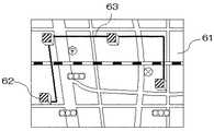
図11はこの実施の形態3の管理装置を示す図である。この実施の形態3の管理装置では、図2に示したものに加え、地図情報を保持するための地図情報保持部37と、データベース33に格納されている電力線物理経路情報、データベース34に格納されている通信装置物理位置情報、地図情報保持部41に格納されている地図情報を重ね合わせて表示するための重ね合わせ表示部38を備えている。尚、その他は実施の形態1、2と同様である。Embodiment 3 FIG.
FIG. 11 is a diagram showing a management apparatus according to the third embodiment. In the management apparatus of the third embodiment, in addition to the one shown in FIG. 2, a map
図12はこの実施の形態3の表示部38が表示する重ね合わせ表示の例を示す図である。図12に示すように、ここでは、背面に地図情報保持部37から取り出した地図61が表示され、この地図61上にデータベース34から取り出された通信装置の位置に応じて通信装置を示すアイコン62が表示されている。そして、データベース33から取り出された電力線の経路63がこれらと共に表示されている。 FIG. 12 is a diagram showing an example of superimposed display displayed by the
これらの情報を重ね合わせて表示することにより、各通信装置がどこに位置し、電力線とどのように接続されているかが一目瞭然となり、通信装置の管理が容易になるという効果がある。 By superimposing and displaying these pieces of information, it becomes obvious at a glance where each communication device is located and how it is connected to the power line, and there is an effect that management of the communication device becomes easy.
1 電力線 3 管理装置
5、5a、5b、5c、5d、5e 通信装置
31 電力線搬送通信部 32 演算部
33、34 データベース 35 通信装置通信状態取得部
36 通信装置物理位置算出部 37 地図情報保持部
38 表示部
41 結合回路 42 モデム
43 CPU 44 メモリ
45 電源回路
51 電力線搬送通信部 53 通信状態保持部
61 地図 62 アイコン
63 経路
DESCRIPTION OF SYMBOLS 1 Power line 3
Claims (8)
Translated fromJapanese第1の通信装置の物理的な位置に関する情報が格納された記憶部と、第1、第2の通信装置間の通信状態を検出する検出部と、前記検出部で検出された通信状態に基づき、前記第1の通信装置と前記第2の通信装置との相対位置を算出する相対位置算出部と、前記相対位置算出部で算出された相対位置と前記記憶部に格納されている前記第1の通信装置の物理的な位置に関する情報とから前記第2の通信装置の物理的な位置を算出し、算出された前記第2の通信装置の物理的な位置に関する情報を前記記憶部に格納する演算部とを備えた電力線搬送通信システム。A power line carrier communication system in which a plurality of communication devices that perform communication via a power line are arranged on the power line,
Based on a storage unit that stores information on the physical position of the first communication device, a detection unit that detects a communication state between the first and second communication devices, and a communication state detected by the detection unit A relative position calculation unit that calculates a relative position between the first communication device and the second communication device, a relative position calculated by the relative position calculation unit, and the first stored in the storage unit. The physical position of the second communication apparatus is calculated from the information regarding the physical position of the second communication apparatus, and the calculated information regarding the physical position of the second communication apparatus is stored in the storage unit. A power line carrier communication system comprising a calculation unit.
前記相対位置算出部は、前記受信信号を送信した通信装置の送信信号の強度と前記通信状態とに基づき、前記相対位置を算出する請求項1に記載の電力線搬送通信システム。The communication state is the signal strength of the received signal,
2. The power line carrier communication system according to claim 1, wherein the relative position calculation unit calculates the relative position based on a transmission signal strength of the communication apparatus that has transmitted the reception signal and the communication state.
前記検出部は、前記第1、第2の通信装置間の第1の通信状態を検出する第1の検出部と、前記第3、第2の通信装置間の第2の通信状態を検出する第2の検出部とを有し、
前記相対位置検出部は、前記第1、第2の通信状態に基づき、前記第2の通信装置と前記第1及び第3の通信装置との相対位置を算出し、
前記算出部は、前記第3の通信装置の物理的な位置に関する情報も考慮して前記第2の通信装置の物理的な位置を算出する請求項1に記載の電力線搬送通信システム。The storage unit stores information related to the physical position of the third communication device,
The detection unit detects a first communication state between the first and second communication devices, and detects a second communication state between the third and second communication devices. A second detection unit,
The relative position detector calculates a relative position between the second communication device and the first and third communication devices based on the first and second communication states;
The power line carrier communication system according to claim 1, wherein the calculation unit calculates a physical position of the second communication device in consideration of information regarding a physical position of the third communication device.
第1の通信装置の物理的な位置に関する情報が格納された記憶部と、第1、第2の通信装置間の通信状態を取得する取得部と、前記取得部で取得された通信状態に基づき、前記第1の通信装置と前記第2の通信装置との相対位置を算出する相対位置算出部と、前記相対位置算出部で算出された相対位置と前記記憶部に格納されている前記第1の通信装置の物理的な位置に関する情報とから前記第2の通信装置の物理的な位置を算出し、算出された前記第2の通信装置の物理的な位置に関する情報を前記記憶部に格納する演算部とを備えた通信装置。A communication device that communicates with another communication device via a power line,
Based on a storage unit that stores information on the physical position of the first communication device, an acquisition unit that acquires a communication state between the first and second communication devices, and a communication state acquired by the acquisition unit A relative position calculation unit that calculates a relative position between the first communication device and the second communication device, a relative position calculated by the relative position calculation unit, and the first stored in the storage unit. The physical position of the second communication apparatus is calculated from the information regarding the physical position of the second communication apparatus, and the calculated information regarding the physical position of the second communication apparatus is stored in the storage unit. A communication device comprising an arithmetic unit.
前記電力線に新設の通信装置を配置するステップと、既に前記電力線に設置されその位置が特定されている既設の通信装置と前記新設の通信装置とで通信を行いその通信状態を取得する取得ステップと、前記通信状態に基づき前記新設の通信装置と前記既設の通信装置との相対位置を求める相対位置算出ステップと、前記相対位置算出ステップで求められた相対位置と既に位置が特定されている前記既設の通信装置の位置とから前記新設の通信装置の物理的な位置を特定するステップとを含む電力線搬送通信システムの構築方法。A construction method of a power line carrier communication system for constructing a network composed of a plurality of communication devices by arranging a newly installed communication device on a power line and specifying its position,
A step of arranging a new communication device on the power line, and an acquisition step of performing communication between the existing communication device already installed on the power line and specifying the position thereof and the new communication device to acquire the communication state; A relative position calculating step for obtaining a relative position between the new communication device and the existing communication device based on the communication state; and the relative position obtained in the relative position calculating step and the existing position are already specified. A method for constructing a power line carrier communication system, comprising: identifying a physical position of the newly installed communication device from the position of the communication device.
前記相対位置算出ステップは、前記取得ステップで取得された複数の通信状態から前記相対位置を算出する請求項7に記載の電力線搬送通信システムの構築方法。The acquisition step acquires a plurality of communication states obtained by communication between a plurality of existing communication devices and the new communication device,
The construction method of the power line carrier communication system according to claim 7, wherein the relative position calculation step calculates the relative position from a plurality of communication states acquired in the acquisition step.
Priority Applications (2)
| Application Number | Priority Date | Filing Date | Title |
|---|---|---|---|
| JP2005056239AJP2006245802A (en) | 2005-03-01 | 2005-03-01 | Power line carrier communication system, communication device therefor, and power line carrier communication system construction method |
| US11/316,747US7362085B2 (en) | 2005-03-01 | 2005-12-27 | Power line carrier communication system and its communication device, and method for constructing power line carrier communication system |
Applications Claiming Priority (1)
| Application Number | Priority Date | Filing Date | Title |
|---|---|---|---|
| JP2005056239AJP2006245802A (en) | 2005-03-01 | 2005-03-01 | Power line carrier communication system, communication device therefor, and power line carrier communication system construction method |
Publications (1)
| Publication Number | Publication Date |
|---|---|
| JP2006245802Atrue JP2006245802A (en) | 2006-09-14 |
Family
ID=37009646
Family Applications (1)
| Application Number | Title | Priority Date | Filing Date |
|---|---|---|---|
| JP2005056239APendingJP2006245802A (en) | 2005-03-01 | 2005-03-01 | Power line carrier communication system, communication device therefor, and power line carrier communication system construction method |
Country Status (2)
| Country | Link |
|---|---|
| US (1) | US7362085B2 (en) |
| JP (1) | JP2006245802A (en) |
Cited By (2)
| Publication number | Priority date | Publication date | Assignee | Title |
|---|---|---|---|---|
| JP2010056656A (en)* | 2008-08-26 | 2010-03-11 | Fujitsu Ltd | Display position decision device, display position decision method, and computer program |
| WO2010067748A1 (en)* | 2008-12-12 | 2010-06-17 | 三菱電機株式会社 | Power line carrier communication method, power line carrier communication system, and repeater for power line carrier communication system |
Families Citing this family (8)
| Publication number | Priority date | Publication date | Assignee | Title |
|---|---|---|---|---|
| JP2008258850A (en)* | 2007-04-03 | 2008-10-23 | Omron Corp | Communication checker, communication-state detection system, and method for checking communication state |
| EP2154789B1 (en)* | 2008-08-11 | 2019-10-02 | Sony Corporation | Method for detecting an ingress of a short-wave radio signal in a power line communication system and power line communication modem |
| EP2446519B1 (en)* | 2009-06-26 | 2019-09-11 | ABB Schweiz AG | Load scheduling optimization in distributed system |
| US8296494B1 (en)* | 2010-03-31 | 2012-10-23 | The Boeing Company | Expanded electronic bus communication capacity |
| US20110246793A1 (en)* | 2010-04-01 | 2011-10-06 | Xyratex Technology Limited | Method of providing out of band monitoring and control of a data storage subsystem |
| JP2013038380A (en)* | 2011-07-08 | 2013-02-21 | Sony Corp | Test circuit, integrated circuit, and layout method of test circuit |
| US20130121427A1 (en)* | 2011-11-15 | 2013-05-16 | Texas Instruments Incorporated | Scaled power line based network |
| KR102085202B1 (en)* | 2014-04-14 | 2020-03-05 | 엘에스산전 주식회사 | Three-phase power line communication apparatus and method for communicating three-phase power line communication apparatus |
Family Cites Families (8)
| Publication number | Priority date | Publication date | Assignee | Title |
|---|---|---|---|---|
| US6097298A (en)* | 1998-02-13 | 2000-08-01 | Ecsi Corporation | Apparatus and method of monitoring a power transmission line |
| WO2000074306A2 (en)* | 1999-05-28 | 2000-12-07 | Basic Resources, Inc. | Wireless transceiver network employing node-to-node data messaging |
| US7173935B2 (en)* | 2002-06-07 | 2007-02-06 | Current Grid, Llc | Last leg utility grid high-speed data communication network having virtual local area network functionality |
| US20030217150A1 (en)* | 2002-03-01 | 2003-11-20 | Roese John J. | Location based enhanced routing |
| JP2004064355A (en) | 2002-07-26 | 2004-02-26 | Matsushita Electric Works Ltd | Power line carrier communication system and attribute information setting method for terminal used for the same |
| US6980091B2 (en)* | 2002-12-10 | 2005-12-27 | Current Technologies, Llc | Power line communication system and method of operating the same |
| US7627402B2 (en)* | 2005-10-21 | 2009-12-01 | Current Technologies, Llc | Device and method for designing power line communication system networks |
| US20070160373A1 (en)* | 2005-12-22 | 2007-07-12 | Palo Alto Research Center Incorporated | Distributed illumination and sensing system |
- 2005
- 2005-03-01JPJP2005056239Apatent/JP2006245802A/enactivePending
- 2005-12-27USUS11/316,747patent/US7362085B2/ennot_activeExpired - Fee Related
Cited By (3)
| Publication number | Priority date | Publication date | Assignee | Title |
|---|---|---|---|---|
| JP2010056656A (en)* | 2008-08-26 | 2010-03-11 | Fujitsu Ltd | Display position decision device, display position decision method, and computer program |
| WO2010067748A1 (en)* | 2008-12-12 | 2010-06-17 | 三菱電機株式会社 | Power line carrier communication method, power line carrier communication system, and repeater for power line carrier communication system |
| JPWO2010067748A1 (en)* | 2008-12-12 | 2012-05-17 | 三菱電機株式会社 | Power line carrier communication method, power line carrier communication system, and repeater of power line carrier communication system |
Also Published As
| Publication number | Publication date |
|---|---|
| US20060208742A1 (en) | 2006-09-21 |
| US7362085B2 (en) | 2008-04-22 |
Similar Documents
| Publication | Publication Date | Title |
|---|---|---|
| CN104769391B (en) | Method and system for determining course deviation for a section of road | |
| US9443159B2 (en) | Target identification system target identification server and target identification terminal | |
| KR101534716B1 (en) | System and method for providing weather information | |
| US7843496B2 (en) | Imaging device, method of recording location information, and computer program product | |
| US9335176B2 (en) | Information processing device, processing method, and medium | |
| EP1582843A1 (en) | Traffic information providing system | |
| US20070239355A1 (en) | Method and apparatus for preventing separation of accompanying persons | |
| JP2006245802A (en) | Power line carrier communication system, communication device therefor, and power line carrier communication system construction method | |
| KR101014967B1 (en) | Parking location guidance system and method of the vehicle | |
| KR20090128074A (en) | Portable wireless terminal, fixed wireless terminal and indoor positioning system and method using same | |
| JP6901915B2 (en) | Train approach warning system | |
| US20060179355A1 (en) | Autonomous network fault detection and management system | |
| JP2012013613A (en) | System, apparatus and program for gnss analysis | |
| JP2006118998A (en) | Ic tag reader locating apparatus and ic tag reader locating method | |
| JP6960183B2 (en) | Field information display system | |
| JP2007329581A (en) | Network equipment management system | |
| JP2019032793A (en) | Operation management device, operation management method, and operation management system | |
| JP4859405B2 (en) | Inspection construction management device, inspection construction management system, and inspection construction management method | |
| KR101342870B1 (en) | Positioning system and method | |
| CN108810819A (en) | A kind of earth's surface localization method and medium based on network communication | |
| CN106871920B (en) | Navigation method and electronic equipment applying same | |
| JPH11281389A (en) | Location confirmation guidance system and mobile terminal | |
| JP2008092169A (en) | Communication terminal apparatus, center device, and remote control system | |
| US10764711B2 (en) | Content distribution server and content distribution method | |
| KR101336797B1 (en) | System and Method for Tourist Guide using Location Based Service |
Legal Events
| Date | Code | Title | Description |
|---|---|---|---|
| A621 | Written request for application examination | Free format text:JAPANESE INTERMEDIATE CODE: A621 Effective date:20061213 | |
| A977 | Report on retrieval | Free format text:JAPANESE INTERMEDIATE CODE: A971007 Effective date:20090120 | |
| A131 | Notification of reasons for refusal | Free format text:JAPANESE INTERMEDIATE CODE: A131 Effective date:20090127 | |
| A02 | Decision of refusal | Free format text:JAPANESE INTERMEDIATE CODE: A02 Effective date:20090602 |