JP2006245159A - Manufacturing method of semiconductor device - Google Patents
Manufacturing method of semiconductor deviceDownload PDFInfo
- Publication number
- JP2006245159A JP2006245159AJP2005056898AJP2005056898AJP2006245159AJP 2006245159 AJP2006245159 AJP 2006245159AJP 2005056898 AJP2005056898 AJP 2005056898AJP 2005056898 AJP2005056898 AJP 2005056898AJP 2006245159 AJP2006245159 AJP 2006245159A
- Authority
- JP
- Japan
- Prior art keywords
- sacrificial layer
- source electrode
- semiconductor device
- forming
- wiring
- Prior art date
- Legal status (The legal status is an assumption and is not a legal conclusion. Google has not performed a legal analysis and makes no representation as to the accuracy of the status listed.)
- Granted
Links
Images


Classifications
- H—ELECTRICITY
- H10—SEMICONDUCTOR DEVICES; ELECTRIC SOLID-STATE DEVICES NOT OTHERWISE PROVIDED FOR
- H10D—INORGANIC ELECTRIC SEMICONDUCTOR DEVICES
- H10D84/00—Integrated devices formed in or on semiconductor substrates that comprise only semiconducting layers, e.g. on Si wafers or on GaAs-on-Si wafers
- H10D84/01—Manufacture or treatment
- H—ELECTRICITY
- H01—ELECTRIC ELEMENTS
- H01L—SEMICONDUCTOR DEVICES NOT COVERED BY CLASS H10
- H01L21/00—Processes or apparatus adapted for the manufacture or treatment of semiconductor or solid state devices or of parts thereof
- H01L21/70—Manufacture or treatment of devices consisting of a plurality of solid state components formed in or on a common substrate or of parts thereof; Manufacture of integrated circuit devices or of parts thereof
- H01L21/71—Manufacture of specific parts of devices defined in group H01L21/70
- H01L21/76—Making of isolation regions between components
- H01L21/764—Air gaps
Landscapes
- Engineering & Computer Science (AREA)
- Physics & Mathematics (AREA)
- Condensed Matter Physics & Semiconductors (AREA)
- General Physics & Mathematics (AREA)
- Manufacturing & Machinery (AREA)
- Computer Hardware Design (AREA)
- Microelectronics & Electronic Packaging (AREA)
- Power Engineering (AREA)
- Junction Field-Effect Transistors (AREA)
Abstract
Translated fromJapaneseDescription
Translated fromJapanese本発明は、半導体装置の製造方法に関し、特に、高周波で動作するトランジスタの製造方法に関する。 The present invention relates to a method for manufacturing a semiconductor device, and more particularly to a method for manufacturing a transistor that operates at a high frequency.
近年、携帯電話等に代表される移動体通信機器市場の世界的な拡大、及び衛星通信サービスの急速な普及により、高周波で動作する電子回路の需要が飛躍的に増加している。さらに、伝送される情報量の増大に伴い、より高い周波数での通信が必要とされている。このような要求に応えるために、マイクロ波領域の高い周波数で動作する、化合物半導体基板上に形成されるMMIC(Monolithic Microwave Integrated Circuit)の開発が盛んに行われている。 In recent years, the demand for electronic circuits operating at high frequencies has increased dramatically due to the global expansion of the mobile communication device market represented by mobile phones and the like and the rapid spread of satellite communication services. Furthermore, with an increase in the amount of information to be transmitted, communication at a higher frequency is required. In order to meet such a demand, MMIC (Monolithic Microwave Integrated Circuit) formed on a compound semiconductor substrate that operates at a high frequency in the microwave region has been actively developed.
MMICの中でも特に重要な素子はトランジスタであるが、化合物半導体は電子移動度が高いため、トランジスタは非常に高速で動作する。このようなトランジスタの一つとして、高電子移動度トランジスタ(High Electron Mobility Transistor:HEMT)と呼ばれているものがある。 A particularly important element in the MMIC is a transistor. However, since a compound semiconductor has high electron mobility, the transistor operates at a very high speed. One of such transistors is a so-called high electron mobility transistor (HEMT).
以下、従来のHEMTの構造について説明する。化合物半導体基板上に電子走行層が形成されており、電子走行層上に電子供給層が形成されている。電子供給層上には、第1〜第3の高濃度ドープ層が部分的に形成されている。第1の高濃度ドープ層上には第1のソース電極が形成されており、第2の高濃度ドープ層上にはドレイン電極が形成されており、第3の高濃度ドープ層上には第2のソース電極が形成されている。第1の高濃度ドープ層と第2の高濃度ドープ層との間における電子供給層上には、オーバーハング形状の第1のゲート電極が形成されている。第2の高濃度ドープ層と第3の高濃度ドープ層との間における電子供給層上には、オーバーハング形状の第2のゲート電極が形成されている。第1及び第2のゲート電極を覆って、比誘電率が4〜5程度の樹脂が形成されている。樹脂上には、金属配線が形成されている。金属配線は、樹脂内に形成された第1及び第2のコンタクトホールを介して、第1及び第2のソース電極に接続されている。 Hereinafter, the structure of a conventional HEMT will be described. An electron transit layer is formed on the compound semiconductor substrate, and an electron supply layer is formed on the electron transit layer. First to third heavily doped layers are partially formed on the electron supply layer. A first source electrode is formed on the first heavily doped layer, a drain electrode is formed on the second heavily doped layer, and a first electrode is formed on the third heavily doped layer. Two source electrodes are formed. An overhang-shaped first gate electrode is formed on the electron supply layer between the first heavily doped layer and the second heavily doped layer. An overhang-shaped second gate electrode is formed on the electron supply layer between the second heavily doped layer and the third heavily doped layer. A resin having a relative dielectric constant of about 4 to 5 is formed so as to cover the first and second gate electrodes. Metal wiring is formed on the resin. The metal wiring is connected to the first and second source electrodes through first and second contact holes formed in the resin.
第1及び第2のゲート電極に印加するゲート電圧によって、電子供給層から電子走行層へ供給される電子の量を調整することにより、ソース電極とドレイン電極との間を流れる電流量が制御される。 The amount of current flowing between the source electrode and the drain electrode is controlled by adjusting the amount of electrons supplied from the electron supply layer to the electron transit layer by the gate voltage applied to the first and second gate electrodes. The
なお、HEMTのゲート電極の周囲に空気層を形成する技術が、下記特許文献1〜3に開示されている。 In addition, the technique of forming an air layer around the gate electrode of HEMT is disclosed by the following patent documents 1-3.
上記したHEMTの構造では、第1及び第2の高濃度ドープ層と第1のゲート電極との間、並びに、第2及び第3の高濃度ドープ層と第2のゲート電極との間に、本質的で避けられないキャパシタが存在する。従来のHEMTでは、比誘電率が4〜5程度の樹脂が第1及び第2のゲート電極を覆って形成されているため、これらのキャパシタは比較的大きな寄生容量となる。その結果、従来のHEMTには、この寄生容量に起因して、高周波領域におけるデバイスの電気的特性が低下するという問題がある。 In the above-described HEMT structure, between the first and second heavily doped layers and the first gate electrode, and between the second and third heavily doped layers and the second gate electrode, There are capacitors that are essential and inevitable. In the conventional HEMT, since a resin having a relative dielectric constant of about 4 to 5 is formed to cover the first and second gate electrodes, these capacitors have a relatively large parasitic capacitance. As a result, the conventional HEMT has a problem that the electrical characteristics of the device in the high frequency region are deteriorated due to this parasitic capacitance.
本発明はかかる問題を解決するために成されたものであり、高周波領域において優れた電気的特性が得られるように、寄生容量を低減し得る半導体装置の製造方法を得ることを目的とする。 The present invention has been made to solve such a problem, and an object of the present invention is to provide a method of manufacturing a semiconductor device capable of reducing parasitic capacitance so that excellent electrical characteristics can be obtained in a high frequency region.
第1の発明に係る半導体装置の製造方法は、(a)第1のソース電極、ゲート電極、ドレイン電極、及び第2のソース電極が、第1方向に沿ってこの順に並んで半導体基板の上面上に形成された構造を有するトランジスタを形成する工程と、(b)前記第1方向に垂直な第2方向に関して前記トランジスタを挟む第1の側壁及び第2の側壁を、前記半導体基板の前記上面上に形成する工程と、(c)犠牲層を、前記トランジスタを覆って前記半導体基板の前記上面上に形成する工程と、(d)前記犠牲層を部分的に除去することにより、前記第1のソース電極及び前記第2のソース電極を露出する工程と、(e)前記工程(d)よりも後に実行され、前記第1の側壁及び前記第2の側壁に接触し、前記第1のソース電極及び前記第2のソース電極に接続され、前記第1方向に沿って延在する配線を、前記犠牲層の上面上に形成する工程と、(f)前記工程(e)よりも後に実行され、前記犠牲層を除去する工程とを備える。 According to a first aspect of the present invention, there is provided a semiconductor device manufacturing method comprising: (a) a first source electrode, a gate electrode, a drain electrode, and a second source electrode arranged in this order along a first direction; Forming a transistor having a structure formed thereon; and (b) defining a first sidewall and a second sidewall sandwiching the transistor in a second direction perpendicular to the first direction, the upper surface of the semiconductor substrate. (C) forming a sacrificial layer on the upper surface of the semiconductor substrate so as to cover the transistor; (d) partially removing the sacrificial layer; Exposing the source electrode and the second source electrode; and (e) performed after the step (d), contacting the first sidewall and the second sidewall, and the first source Electrode and second source A step of forming a wiring connected to the pole and extending along the first direction on the upper surface of the sacrificial layer; and (f) performed after the step (e) to remove the sacrificial layer. A process.
第2の発明に係る半導体装置の製造方法は、(a)第1のソース電極、ゲート電極、ドレイン電極、及び第2のソース電極が、所定方向に沿ってこの順に並んで半導体基板の上面上に形成された構造を有するトランジスタを形成する工程と、(b)犠牲層を、前記トランジスタを覆って前記半導体基板の前記上面上に形成する工程と、(c)前記犠牲層を部分的に除去することにより、前記第1のソース電極及び前記第2のソース電極を露出する工程と、(d)前記工程(c)よりも後に実行され、前記第1のソース電極及び前記第2のソース電極に接続され、前記所定方向に沿って延在する配線を、前記犠牲層の上面上に形成する工程と、(e)前記工程(d)よりも後に実行され、前記犠牲層を除去する工程と、(f)前記工程(e)よりも後に実行され、前記トランジスタ及び前記配線を覆う形状に加工されたシート、テープ、又は基板を、前記トランジスタ及び前記配線を覆って前記半導体基板の前記上面上に貼り付ける工程とを備える。 According to a second aspect of the present invention, there is provided a semiconductor device manufacturing method comprising: (a) a first source electrode, a gate electrode, a drain electrode, and a second source electrode arranged in this order along a predetermined direction on an upper surface of a semiconductor substrate; Forming a transistor having a structure formed on the semiconductor substrate; (b) forming a sacrificial layer on the upper surface of the semiconductor substrate so as to cover the transistor; and (c) partially removing the sacrificial layer. A step of exposing the first source electrode and the second source electrode, and (d) performed after the step (c), wherein the first source electrode and the second source electrode are performed. And (e) a step of removing the sacrificial layer, which is performed after the step (d), and is formed on the upper surface of the sacrificial layer. (F) From step (e) above Also be performed later, the transistor and the sheet is processed into a shape to cover the wiring, tape, or the substrate, and a step of attaching covering the transistors and the wiring on the upper surface of the semiconductor substrate.
第3の発明に係る半導体装置の製造方法は、(a)第1のソース電極、ゲート電極、ドレイン電極、及び第2のソース電極が、所定方向に沿ってこの順に並んで半導体基板の上面上に形成された構造を有するトランジスタを形成する工程と、(b)犠牲層を、前記トランジスタを覆って前記半導体基板の前記上面上に形成する工程と、(c)前記犠牲層を部分的に除去することにより、前記第1のソース電極及び前記第2のソース電極を露出する工程と、(d)前記工程(c)よりも後に実行され、前記第1のソース電極及び前記第2のソース電極に接続され、前記所定方向に沿って延在する配線を、前記犠牲層の上面上に形成する工程と、(e)前記工程(d)よりも後に実行され、前記犠牲層を除去する工程と、(f)上面が開口した枠体を、前記トランジスタの周囲を取り囲んで、前記半導体基板の前記上面上に形成する工程と、(g)前記枠体上にテープを貼り付けることにより、前記枠体及び前記テープによって前記トランジスタ及び前記配線を覆う工程とを備える。 According to a third aspect of the present invention, there is provided a semiconductor device manufacturing method comprising: (a) a first source electrode, a gate electrode, a drain electrode, and a second source electrode arranged in this order along a predetermined direction on an upper surface of a semiconductor substrate; Forming a transistor having a structure formed on the semiconductor substrate; (b) forming a sacrificial layer on the upper surface of the semiconductor substrate so as to cover the transistor; and (c) partially removing the sacrificial layer. A step of exposing the first source electrode and the second source electrode, and (d) performed after the step (c), wherein the first source electrode and the second source electrode are performed. And (e) a step of removing the sacrificial layer, which is performed after the step (d), and is formed on the upper surface of the sacrificial layer. (F) A frame with an open top surface Enclosing a periphery of the transistor and forming it on the upper surface of the semiconductor substrate; and (g) pasting a tape on the frame to thereby form the transistor and the wiring with the frame and the tape. And a step of covering.
第1〜第3の発明に係る半導体装置の製造方法によれば、寄生容量が低減され、高周波領域において優れた電気的特性を示す半導体装置を得ることができる。 According to the method for manufacturing a semiconductor device according to the first to third inventions, it is possible to obtain a semiconductor device with reduced parasitic capacitance and excellent electrical characteristics in a high frequency region.
実施の形態1.
図1は、本発明の実施の形態1に係る半導体装置の構造を示す上面図であり、図2,3は、それぞれ図1に示したラインII−II,III−IIIに沿った位置に関する断面構造を示す断面図である。
FIG. 1 is a top view showing the structure of the semiconductor device according to the first embodiment of the present invention. FIGS. 2 and 3 are cross-sectional views taken along lines II-II and III-III shown in FIG. 1, respectively. It is sectional drawing which shows a structure.
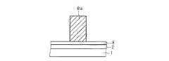
図2を参照して、本実施の形態1に係るHEMTは、GaAs基板等の化合物半導体基板1、電子走行層2、電子供給層3、高濃度ドープ層4a,4b,5、ソース電極6a,6b、ドレイン電極7、及びオーバーハング形状のゲート電極8a,8bを有している。電子走行層2は、化合物半導体基板1上に全面的に形成されている。電子供給層3は、電子走行層2上に全面的に形成されている。高濃度ドープ層4a,4b,5は、互いに離間しつつ電子供給層3上に部分的に形成されている。以下の説明では、化合物半導体基板1、電子走行層2、電子供給層3、及び高濃度ドープ層4a,4b,5をまとめて、「半導体基板」と称する場合もある。 Referring to FIG. 2, the HEMT according to the first embodiment includes a
ソース電極6aは高濃度ドープ層4a上に形成されており、ソース電極6bは高濃度ドープ層4b上に形成されており、ドレイン電極7は高濃度ドープ層5上に形成されている。ゲート電極8aは、高濃度ドープ層4aと高濃度ドープ層5との間における電子供給層3上に形成されており、ゲート電極8bは、高濃度ドープ層4bと高濃度ドープ層5との間における電子供給層3上に形成されている。ソース電極6a,6bには、金属配線9が接続されている。 The
図3を参照して、半導体基板上には、側壁11a,11bが形成されている。側壁11a,11bの材質は、ポリイミド系樹脂、エポキシ系樹脂、又はフッ素系ポリマー樹脂等の、感光性樹脂である。側壁11a,11bの高さは、ゲート電極8aの高さよりも高い。金属配線9は、側壁11a,11bに接触して形成されている。金属配線9には、金属配線9の上面から底面まで貫通するスリット12が形成されている。 Referring to FIG. 3,
図2,3を参照して、ゲート電極8a,8bの周囲には、空気層10が形成されている。空気層10は、金属配線9と、側壁11a,11bと、半導体基板の上面とによって規定されている。 2 and 3, an
図1を参照して、ソース電極6a、ゲート電極8a、ドレイン電極7、ゲート電極8b、及びソース電極6bは、紙面の横方向(以下「第1方向」と称す)に沿ってこの順に並んで形成されている。側壁11a,11b及び金属配線9は、第1方向に沿って延在して形成されている。側壁11a,11bは、紙面の縦方向(以下「第2方向」と称す)に関して両側からHEMTを挟んでいる。金属配線9には、複数個の開口部(図1に示した例では6個のスリット12)が形成されている。スリット12の寸法は、例えば、幅が1μmであり、長さが20μmである。但し、長方形状のスリット12の代わりに、正方形状又は円形状の小孔を形成してもよい。 Referring to FIG. 1,
図4〜7は、図2に対応させて、本実施の形態1に係る半導体装置の製造方法を工程順に示す断面図であり、図8〜12は、図3に対応させて、本実施の形態1に係る半導体装置の製造方法を工程順に示す断面図である。 4 to 7 are cross-sectional views illustrating the manufacturing method of the semiconductor device according to the first embodiment in the order of steps corresponding to FIG. 2, and FIGS. 8 to 12 correspond to FIG. FIG. 10 is a cross-sectional view illustrating the manufacturing method of the semiconductor device according to the first embodiment in order of processes.
図4,8を参照して、まず、周知のHEMT製造プロセスを経ることにより、化合物半導体基板1、電子走行層2、電子供給層3、高濃度ドープ層4a,4b,5、ソース電極6a,6b、ドレイン電極7、及びゲート電極8a,8bを有するHEMTを形成する。 4 and 8, first, through a well-known HEMT manufacturing process,
図9を参照して、次に、写真製版法によって、半導体基板上に側壁11a,11bを形成する。 Referring to FIG. 9, next,
図5,10を参照して、次に、写真製版法によって、側壁11a,11bが形成されていない部分の半導体基板上に、側壁11a,11bの材質とは異なる感光性樹脂から成る犠牲層15を形成する。図5に示すように、犠牲層15は、HEMTを覆って形成されている。 Referring to FIGS. 5 and 10, a
図6を参照して、次に、犠牲層15を部分的に露光した後に現像処理を行うことにより、犠牲層15内にコンタクトホール16a,16bを形成する。これにより、ソース電極6a,6bの各上面が露出する。 Referring to FIG. 6, next, contact holes 16 a and 16 b are formed in the
図7,11を参照して、次に、蒸着法によって、金等の金属膜を犠牲層15及び側壁11a,11b上に全面的に形成する。次に、その金属膜をパターニングすることにより、金属配線9を形成する。 Next, referring to FIGS. 7 and 11, a metal film such as gold is formed on the entire surface of the
図12を参照して、次に、写真製版法及びエッチング法によって金属配線9を部分的に除去することにより、スリット12を形成する。これにより、犠牲層15の上面が部分的に露出する。 Referring to FIG. 12, next, the
その後、側壁11a,11bを溶解せず犠牲層15を溶解する有機アミン系の溶剤を用いて、犠牲層15を溶解する。次に、溶解された犠牲層15を、スリット12を介して外部に排出する。犠牲層15が除去された結果、空気層10が形成され、これにより、図2,3に示した構造が得られる。犠牲層15を除去した後にスリット12は塞がれるが、その方法については後述の実施の形態2〜5において説明する。 Thereafter, the
本実施の形態1に係るHEMTによると、図2に示したように、ゲート電極8a,8bの周囲に空気層10が形成されている。空気層10の比誘電率は1程度である。従って、比誘電率が4〜5程度の樹脂によってゲート電極が覆われている従来のHEMTと比較すると、ゲート電極8a,8bと高濃度ドープ層4a,4b,5との間に形成される寄生容量を、70〜80%程度低減することができる。その結果、高周波領域におけるデバイスの電気的特性を大幅に向上することが可能となる。 According to the HEMT according to the first embodiment, as shown in FIG. 2, the
また、半導体基板上に側壁11a,11bが形成されており、空気層10の上面及び側面は、金属配線9と側壁11a,11bとによって完全に密閉されている。従って、後工程で半導体装置を樹脂封止する際に、封止用の樹脂が空気層10内に流入してくることを回避できる。 Further,
実施の形態2.
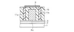
図13,14は、それぞれ図2,3に対応させて、本発明の実施の形態2に係る半導体装置の構造を示す断面図である。Ta2O5,BST,STO等の絶縁膜20が金属配線9上に形成されており、スリット12は絶縁膜20によって塞がれている。
13 and 14 are cross-sectional views showing the structure of the semiconductor device according to the second embodiment of the present invention, corresponding to FIGS. An insulating
図2,3に示した構造を得た後、CVD法又は蒸着法によって、絶縁膜20を金属配線9上に全面的に堆積又は蒸着する。スリット12の寸法は、例えば、幅が1μm、長さが20μmであり、絶縁膜20の膜厚は、例えば3μmである。スリット12の幅が非常に狭いため、絶縁膜20の形成工程において、堆積又は蒸着される絶縁膜20はスリット12の内部には侵入せず、スリット12を跨いで形成される。その結果、絶縁膜20によってスリット12が塞がれ、空気層10が密閉される。 After obtaining the structure shown in FIGS. 2 and 3, the insulating
本実施の形態2に係る半導体装置の製造方法によると、スリット12を塞ぐにあたり、成膜技術として一般的に広く用いられているCVD法又は蒸着法を転用できるため、絶縁膜20を容易に形成できるという効果が得られる。 According to the method of manufacturing a semiconductor device according to the second embodiment, the insulating
実施の形態3.
図15,16は、本発明の実施の形態3に係る半導体装置の製造方法を工程順に示す模式図である。
15 and 16 are schematic views showing the method of manufacturing the semiconductor device according to the third embodiment of the present invention in the order of steps.
図15を参照して、液槽24内には、ポリイミド等の粘度の高い樹脂液23が貯留されている。図2,3に示した構造が形成されたウェハ25を、金属配線9を下に向けた状態(つまり、図2,3に示した構造を上下に反転した状態)で、支持棒26によって支持する。そして、その状態でウェハ25を樹脂液23中へディップする。これにより、金属配線9の表面に樹脂液23が塗布される。なお、樹脂液23中へディップする代わりに、スピンコートによって樹脂液23を塗布してもよい。 Referring to FIG. 15, a
図16を参照して、次に、樹脂液23からウェハ25を取り出した後、同じく金属配線9を下に向けた状態(つまり、樹脂液23が塗布された面を下に向けた状態)で、ウェハ25をホットプレート27に対面させることにより、キュアベークを行う。 Referring to FIG. 16, next, after the
図17,18は、それぞれ図2,3に対応させて、本実施の形態3に係る半導体装置の構造を示す断面図である。樹脂液23をキュアベークすることによって得られた樹脂膜28が金属配線9上に形成されており、スリット12は樹脂膜28によって塞がれている。高粘度の樹脂液23が用いられるため、樹脂膜28の形成工程において、塗布される樹脂液23はスリット12の内部には侵入せず、スリット12を跨いで形成される。その結果、樹脂膜28によってスリット12が塞がれ、空気層10が密閉される。 17 and 18 are cross-sectional views showing the structure of the semiconductor device according to the third embodiment, corresponding to FIGS. A
本実施の形態3に係る半導体装置の製造方法によると、スリット12を塞ぐにあたり、一般的に広く用いられている塗布装置を転用できるため、樹脂膜28を容易に形成できるという効果が得られる。 According to the method for manufacturing a semiconductor device according to the third embodiment, since a coating device that is generally widely used can be diverted when the
また、スリット12を塞ぐにあたり、真空装置を使用する必要がないため、上記実施の形態2に係る半導体装置の製造方法と比較すると、コストの低減を図ることができる。 Further, since it is not necessary to use a vacuum device for closing the
さらに、樹脂液23が塗布された面を下に向けた状態でキュアベークを行うため、樹脂液23がスリット12を介して空気層10内へ侵入することを、より確実に防止することができる。 Furthermore, since the cure baking is performed with the surface coated with the
実施の形態4.
図19は、図1に対応させて、本発明の実施の形態4に係る半導体装置の構造を示す上面図であり、図20は、図19に示したラインXX−XXに沿った位置に関する断面構造を示す断面図である。Embodiment 4 FIG.
FIG. 19 is a top view showing the structure of the semiconductor device according to the fourth embodiment of the present invention corresponding to FIG. 1, and FIG. 20 is a cross-sectional view taken along the line XX-XX shown in FIG. It is sectional drawing which shows a structure.
図1〜3に示した構造を得た後、スリット12が形成されている部分の金属配線9の上面上に、高分子系の粘着可能な材質(ポリイミド、ポリエチレンテレフタレート、カーボン等)から成るテープ30を粘着する。その結果、テープ30によってスリット12が塞がれ、空気層10が密閉される。 After obtaining the structure shown in FIGS. 1 to 3, a tape made of a polymer-based adhesive material (polyimide, polyethylene terephthalate, carbon, etc.) on the upper surface of the
本実施の形態4に係る半導体装置の製造方法によると、スリット12を塞ぐにあたり、真空装置を使用する必要がないため、上記実施の形態2に係る半導体装置の製造方法と比較すると、コストの低減を図ることができる。 According to the manufacturing method of the semiconductor device according to the fourth embodiment, since it is not necessary to use a vacuum device when closing the
実施の形態5.
図21は、図1に対応させて、本発明の実施の形態5に係る半導体装置の構造を示す上面図であり、図22は、図21に示したラインXXII−XXIIに沿った位置に関する断面構造を示す断面図である。
FIG. 21 is a top view showing the structure of the semiconductor device according to the fifth embodiment of the present invention, corresponding to FIG. 1, and FIG. 22 is a cross-section regarding the position along line XXII-XXII shown in FIG. It is sectional drawing which shows a structure.
図1〜3に示した構造を得た後、スリット12が形成されている部分の金属配線9の上面上に、ポリイミド等の粘度の高い樹脂インク31をボンディングする。高粘度の樹脂インク31が用いられるため、樹脂インク31はスリット12の内部には侵入せず、スリット12を跨いで形成される。その結果、樹脂インク31によってスリット12が塞がれ、空気層10が密閉される。 After obtaining the structure shown in FIGS. 1 to 3, a
通常、トランジスタの製造プロセスにおいては、トランジスタの電気的特性の検査工程が実行される。そして、検査によって不適格と判定されたトランジスタには、適格と判定されたトランジスタと区別するために、樹脂インクをボンディングすることによって所定の印が付される。スリット12を塞ぐための樹脂インク31のボンディング工程は、不適格なトランジスタへの樹脂インクのボンディング工程と併せて実行することが望ましい。これにより、スリット12を塞ぐための樹脂インク31のボンディング工程を独立の工程として実行する場合と比較すると、コストの低減を図ることができるとともに、全体として、半導体装置の製造に要する時間を短縮することができる。 Usually, in the transistor manufacturing process, an inspection process of the electrical characteristics of the transistor is performed. Then, a transistor determined to be unqualified by the inspection is given a predetermined mark by bonding resin ink in order to distinguish it from a transistor determined to be qualified. The bonding step of the
本実施の形態5に係る半導体装置の製造方法によると、スリット12を塞ぐにあたり、真空装置を使用する必要がないため、上記実施の形態2に係る半導体装置の製造方法と比較すると、コストの低減を図ることができる。 According to the manufacturing method of the semiconductor device according to the fifth embodiment, it is not necessary to use a vacuum device to close the
実施の形態6.
図23,24は、本発明の実施の形態6に係る半導体装置の構造を示す上面図であり、図25,26は、それぞれ図24に示したラインXXV−XXV,XXVI−XXVIに沿った位置に関する断面構造を示す断面図である。但し、図23では、図24に示したシート35の記載を省略している。
23 and 24 are top views showing the structure of the semiconductor device according to the sixth embodiment of the present invention, and FIGS. 25 and 26 are positions along lines XXV-XXV and XXVI-XXVI shown in FIG. 24, respectively. FIG. However, in FIG. 23, the description of the
図23を参照して、本実施の形態6に係る半導体装置は、同一の化合物半導体基板1上に行列状に形成された複数個のHEMTを備えている。図23では、代表的に4個のHEMTのみを示している。各HEMTの構造は、上記実施の形態1に係るHEMTの構造と同様である。 Referring to FIG. 23, the semiconductor device according to the sixth embodiment includes a plurality of HEMTs formed in a matrix on the same
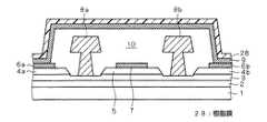
図24〜26を参照して、本実施の形態6に係る半導体装置は、HEMT及び金属配線9を覆う形状に加工されたシート35を備えている。シート35は、例えば高分子系の材質(ポリイミド、ポリエチレンテレフタレート、カーボン等)を用いて形成されている。図24を参照して、各HEMTを覆うシート35が連結部36によって互いに連結されることにより、全体として1枚のシートが構成されている。図25,26を参照して、シート35は、半導体基板上に貼り付けられている。HEMTがシート35によって覆われることにより、ゲート電極8a,8bの周囲には空気層10が形成されている。空気層10は、シート35と、半導体基板の上面とによって規定されている。 24 to 26, the semiconductor device according to the sixth embodiment includes a
図27〜29は、図26に対応させて、本実施の形態6に係る半導体装置の製造方法を工程順に示す断面図である。 27 to 29 are cross-sectional views corresponding to FIG. 26 and illustrating the method of manufacturing the semiconductor device according to the sixth embodiment in the order of steps.
まず、上記実施の形態1と同様の方法によって、図8に示した構造を得る。図27を参照して、次に、半導体基板上に犠牲層15を形成する。図27に示すように、犠牲層15は、HEMTを覆って形成されている。次に、犠牲層15内にコンタクトホール16a,16b(図27には表れない)を形成する。 First, the structure shown in FIG. 8 is obtained by the same method as in the first embodiment. Referring to FIG. 27, next, a
図28を参照して、次に、犠牲層15上に金属膜を形成した後、その金属膜をパターニングすることにより、金属配線9を形成する。次に、金属配線9内にスリット12(図28には表れない)を形成する。但し、本実施の形態6(及び後述の実施の形態7,8)では、スリット12の形成工程は省略しても構わない。 Referring to FIG. 28, next, after forming a metal film on the
図29を参照して、次に、犠牲層15を溶解する溶剤を用いて犠牲層15を溶解した後、溶解された犠牲層15を外部に排出する。 Referring to FIG. 29, next, the
その後、シート35とHEMTとを互いに位置合わせして、シート35を、HEMT及び金属配線9を覆って半導体基板上に貼り付けることにより、図26に示した構造が得られる。 Thereafter, the
本実施の形態6に係るHEMTによると、図25に示したように、ゲート電極8a,8bの周囲に空気層10が形成されている。従って、上記実施の形態1と同様の理由により、高周波領域におけるデバイスの電気的特性を大幅に向上することが可能となる。 According to the HEMT according to the sixth embodiment, as shown in FIG. 25, the
また、半導体基板上にシート35が形成されており、空気層10の上面及び側面は、シート35によって完全に密閉されている。従って、後工程で半導体装置を樹脂封止する際に、封止用の樹脂が空気層10内に流入してくることを防止できる。なお、寄生容量を低減するためには、シート35の形状は少なくともゲート電極8a,8bの周囲を覆う形状であれば足りるが、図24〜26に示したようにHEMT全体をシート35によって覆うことにより、空気層10内への樹脂の流入を防止する効果を高めることができる。 In addition, a
さらに、図24に示したように、各HEMTを覆うシート35が連結部36によって互いに連結されることにより、全体として1枚のシートが構成されている。従って、化合物半導体基板1上に形成された複数個のHEMTを1枚のシートによって同時に覆うことができるため、スループットの向上を図ることができる。 Furthermore, as shown in FIG. 24, the
実施の形態7.
図30,31は、本発明の実施の形態7に係る半導体装置の構造を示す上面図であり、図32は、図31に示したラインXXXII−XXXIIに沿った位置に関する断面構造を示す断面図である。但し、図30では、図31に示したテープ41の記載を省略している。
30 and 31 are top views showing the structure of the semiconductor device according to the seventh embodiment of the present invention, and FIG. 32 is a cross-sectional view showing the cross-sectional structure regarding the position along the line XXXII-XXXII shown in FIG. It is. However, in FIG. 30, the description of the
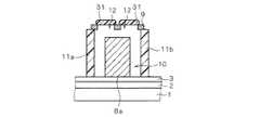
図30〜32を参照して、本実施の形態7に係る半導体装置は、上面が開口した枠状の壁40と、壁40の開口上面を塞ぐように壁40上に貼り付けられたテープ41とを備えている。壁40は、HEMTの周囲を取り囲むように半導体基板上に形成されている。壁40の材質はポリイミド等であり、テープ41は、例えば高分子系の材質を用いて形成されている。図32に示すように、壁40の高さは、半導体基板の上面から金属配線9の上面までの高さよりも高い。HEMTが壁40及びテープ41によって取り囲まれることにより、ゲート電極8a,8bの周囲には空気層10が形成されている。空気層10は、壁40と、テープ41と、半導体基板の上面とによって規定されている。 Referring to FIGS. 30 to 32, the semiconductor device according to the seventh embodiment includes a frame-
図29に示した構造を得た後、写真製版法によって、半導体基板上に壁40を形成する。その後、壁40上にテープ41を貼り付けることにより、図32に示した構造が得られる。 After obtaining the structure shown in FIG. 29, the
本実施の形態7に係るHEMTによると、図31,32に示したように、ゲート電極8a,8bの周囲に空気層10が形成されている。従って、上記実施の形態1と同様の理由により、高周波領域におけるデバイスの電気的特性を大幅に向上することが可能となる。 According to the HEMT according to the seventh embodiment, as shown in FIGS. 31 and 32, the
また、半導体基板上に壁40が形成されており、壁40上にテープ41が貼り付けられているため、空気層10の上面及び側面は完全に密閉されている。従って、後工程で半導体装置を樹脂封止する際に、封止用の樹脂が空気層10内に流入してくることを回避できる。本実施の形態7ではHEMT全体が壁40及びテープ41によって覆われるため、この効果は高い。 Moreover, since the
実施の形態8.
図33は、本発明の実施の形態8に係る半導体装置の構造を示す上面図であり、図34は、図33に示したラインXXXIV−XXXIVに沿った位置に関する断面構造を示す断面図である。
33 is a top view showing the structure of the semiconductor device according to the eighth embodiment of the present invention, and FIG. 34 is a cross-sectional view showing a cross-sectional structure relating to the position along line XXXIV-XXXIV shown in FIG. .
図23と同様に、本実施の形態8に係る半導体装置は、同一の化合物半導体基板1上に行列状に形成された複数個のHEMTを備えている。また、図33,34を参照して、本実施の形態8に係る半導体装置は、HEMT及び金属配線9を覆う形状に加工された壁部46を有する基板45を備えている。基板45は、絶縁基板、又はGaAs基板等の化合物半導体基板である。但し、基板45の代わりに、高分子系の材質によって形成されたテープを用いてもよい。 Similarly to FIG. 23, the semiconductor device according to the eighth embodiment includes a plurality of HEMTs formed in a matrix on the same
図34を参照して、基板45は、半導体基板上に貼り付けられている。HEMTが基板45によって覆われることにより、ゲート電極8a,8bの周囲には空気層10が形成されている。空気層10は、基板45と、半導体基板の上面とによって規定されている。 Referring to FIG. 34,
上記実施の形態6と同様の方法によって図23に示した構造を得た後、互いに隣接するHEMT同士の間に壁部46が挿入されるように基板45を位置合わせして、基板45を半導体基板上に貼り付けることにより、図33,34に示した構造が得られる。 After the structure shown in FIG. 23 is obtained by the same method as in the sixth embodiment, the
本実施の形態8に係るHEMTによると、図34に示したように、ゲート電極8a,8bの周囲に空気層10が形成されている。従って、上記実施の形態1と同様の理由により、高周波領域におけるデバイスの電気的特性を大幅に向上することが可能となる。 According to the HEMT according to the eighth embodiment, as shown in FIG. 34, the
また、半導体基板上に基板45(又はテープ)が形成されており、空気層10の上面及び側面は、基板45によって完全に密閉されている。従って、後工程で半導体装置を樹脂封止する際に、封止用の樹脂が空気層10内に流入してくることを防止できる。本実施の形態8ではHEMT全体が基板45によって覆われるため、この効果は高い。 A substrate 45 (or tape) is formed on the semiconductor substrate, and the upper surface and side surfaces of the
さらに、化合物半導体基板1上に形成された複数個のHEMTを1個の基板45によって同時に覆うことができるため、スループットの向上を図ることができる。 Furthermore, since a plurality of HEMTs formed on the
1 化合物半導体基板、2 電子走行層、3 電子供給層、4a,4b,5 高濃度ドープ層、6a,6b ソース電極、7 ドレイン電極、8a,8b ゲート電極、9 金属配線、10 空気層、11a,11b 側壁、12 スリット、15 犠牲層、16a,16b コンタクトホール、20 絶縁膜、28 樹脂膜、30,41 テープ、31 樹脂インク、35 シート、40 壁、45 基板。
1 Compound semiconductor substrate, 2 electron transit layer, 3 electron supply layer, 4a, 4b, 5 highly doped layer, 6a, 6b source electrode, 7 drain electrode, 8a, 8b gate electrode, 9 metal wiring, 10 air layer,
Claims (8)
Translated fromJapanese(b)前記第1方向に垂直な第2方向に関して前記トランジスタを挟む第1の側壁及び第2の側壁を、前記半導体基板の前記上面上に形成する工程と、
(c)犠牲層を、前記トランジスタを覆って前記半導体基板の前記上面上に形成する工程と、
(d)前記犠牲層を部分的に除去することにより、前記第1のソース電極及び前記第2のソース電極を露出する工程と、
(e)前記工程(d)よりも後に実行され、前記第1の側壁及び前記第2の側壁に接触し、前記第1のソース電極及び前記第2のソース電極に接続され、前記第1方向に沿って延在する配線を、前記犠牲層の上面上に形成する工程と、
(f)前記工程(e)よりも後に実行され、前記犠牲層を除去する工程と
を備える、半導体装置の製造方法。(A) forming a transistor having a structure in which a first source electrode, a gate electrode, a drain electrode, and a second source electrode are arranged in this order along the first direction on the upper surface of the semiconductor substrate; When,
(B) forming a first sidewall and a second sidewall sandwiching the transistor in a second direction perpendicular to the first direction on the upper surface of the semiconductor substrate;
(C) forming a sacrificial layer on the upper surface of the semiconductor substrate so as to cover the transistor;
(D) exposing the first source electrode and the second source electrode by partially removing the sacrificial layer;
(E) executed after the step (d), contacting the first side wall and the second side wall, connected to the first source electrode and the second source electrode, and in the first direction. Forming a wiring extending along the upper surface of the sacrificial layer;
(F) A method for manufacturing a semiconductor device, comprising: a step executed after the step (e) and removing the sacrificial layer.
(h)前記工程(f)よりも後に実行され、前記配線上に絶縁膜を堆積又は蒸着することにより、前記開口部を塞ぐ工程と
をさらに備える、請求項1に記載の半導体装置の製造方法。(G) performing between the step (e) and the step (f), and exposing a part of the upper surface of the sacrificial layer by forming an opening in the wiring;
The method for manufacturing a semiconductor device according to claim 1, further comprising: (h) a step of closing the opening by depositing or vapor-depositing an insulating film on the wiring, which is performed after the step (f). .
(h)前記工程(f)よりも後に実行され、前記配線上に樹脂液を塗布した後にベークを行うことにより、前記開口部を塞ぐ工程と
をさらに備える、請求項1に記載の半導体装置の製造方法。(G) performing between the step (e) and the step (f), and exposing a part of the upper surface of the sacrificial layer by forming an opening in the wiring;
The semiconductor device according to claim 1, further comprising: (h) performing a step after the step (f) and closing the opening by baking after applying a resin liquid on the wiring. Production method.
(h)前記工程(f)よりも後に実行され、前記開口部が形成されている部分の前記配線上にテープを粘着することにより、前記開口部を塞ぐ工程と
をさらに備える、請求項1に記載の半導体装置の製造方法。(G) performing between the step (e) and the step (f), and exposing a part of the upper surface of the sacrificial layer by forming an opening in the wiring;
(H) The method further includes a step of closing the opening by sticking a tape onto the wiring in a portion where the opening is formed, which is executed after the step (f). The manufacturing method of the semiconductor device of description.
(h)前記工程(f)よりも後に実行され、前記開口部が形成されている部分の前記配線上に樹脂インクをボンディングすることにより、前記開口部を塞ぐ工程と
をさらに備える、請求項1に記載の半導体装置の製造方法。(G) performing between the step (e) and the step (f), and exposing a part of the upper surface of the sacrificial layer by forming an opening in the wiring;
(H) The method further includes a step of closing the opening by bonding resin ink onto the wiring in a portion where the opening is formed, which is executed after the step (f). The manufacturing method of the semiconductor device as described in 2. above.
(b)犠牲層を、前記トランジスタを覆って前記半導体基板の前記上面上に形成する工程と、
(c)前記犠牲層を部分的に除去することにより、前記第1のソース電極及び前記第2のソース電極を露出する工程と、
(d)前記工程(c)よりも後に実行され、前記第1のソース電極及び前記第2のソース電極に接続され、前記所定方向に沿って延在する配線を、前記犠牲層の上面上に形成する工程と、
(e)前記工程(d)よりも後に実行され、前記犠牲層を除去する工程と、
(f)前記工程(e)よりも後に実行され、前記トランジスタ及び前記配線を覆う形状に加工されたシート、テープ、又は基板を、前記トランジスタ及び前記配線を覆って前記半導体基板の前記上面上に貼り付ける工程と
を備える、半導体装置の製造方法。(A) forming a transistor having a structure in which a first source electrode, a gate electrode, a drain electrode, and a second source electrode are arranged in this order along a predetermined direction on an upper surface of a semiconductor substrate; ,
(B) forming a sacrificial layer on the top surface of the semiconductor substrate over the transistor;
(C) exposing the first source electrode and the second source electrode by partially removing the sacrificial layer;
(D) A wiring that is executed after the step (c) and is connected to the first source electrode and the second source electrode and extends along the predetermined direction is formed on the upper surface of the sacrificial layer. Forming, and
(E) performing the step after the step (d) and removing the sacrificial layer;
(F) A sheet, tape, or substrate that is executed after the step (e) and is processed to cover the transistor and the wiring is placed on the upper surface of the semiconductor substrate so as to cover the transistor and the wiring. A method for manufacturing a semiconductor device, comprising a step of attaching.
(b)犠牲層を、前記トランジスタを覆って前記半導体基板の前記上面上に形成する工程と、
(c)前記犠牲層を部分的に除去することにより、前記第1のソース電極及び前記第2のソース電極を露出する工程と、
(d)前記工程(c)よりも後に実行され、前記第1のソース電極及び前記第2のソース電極に接続され、前記所定方向に沿って延在する配線を、前記犠牲層の上面上に形成する工程と、
(e)前記工程(d)よりも後に実行され、前記犠牲層を除去する工程と、
(f)上面が開口した枠体を、前記トランジスタの周囲を取り囲んで、前記半導体基板の前記上面上に形成する工程と、
(g)前記枠体上にテープを貼り付けることにより、前記枠体及び前記テープによって前記トランジスタ及び前記配線を覆う工程と
を備える、半導体装置の製造方法。
(A) forming a transistor having a structure in which a first source electrode, a gate electrode, a drain electrode, and a second source electrode are arranged in this order along a predetermined direction on an upper surface of a semiconductor substrate; ,
(B) forming a sacrificial layer on the top surface of the semiconductor substrate over the transistor;
(C) exposing the first source electrode and the second source electrode by partially removing the sacrificial layer;
(D) A wiring that is executed after the step (c) and is connected to the first source electrode and the second source electrode and extends along the predetermined direction is formed on the upper surface of the sacrificial layer. Forming, and
(E) performing the step after the step (d) and removing the sacrificial layer;
(F) forming a frame having an open top surface on the top surface of the semiconductor substrate so as to surround the transistor;
(G) A method of manufacturing a semiconductor device, comprising: a step of covering the transistor and the wiring with the frame and the tape by attaching a tape on the frame.
Priority Applications (2)
| Application Number | Priority Date | Filing Date | Title |
|---|---|---|---|
| JP2005056898AJP4907093B2 (en) | 2005-03-02 | 2005-03-02 | Manufacturing method of semiconductor device |
| US11/295,663US7358179B2 (en) | 2005-03-02 | 2005-12-07 | Method of manufacturing semiconductor device including air space formed around gate electrode |
Applications Claiming Priority (1)
| Application Number | Priority Date | Filing Date | Title |
|---|---|---|---|
| JP2005056898AJP4907093B2 (en) | 2005-03-02 | 2005-03-02 | Manufacturing method of semiconductor device |
Related Child Applications (2)
| Application Number | Title | Priority Date | Filing Date |
|---|---|---|---|
| JP2011257062ADivisionJP5483481B2 (en) | 2011-11-25 | 2011-11-25 | Manufacturing method of semiconductor device |
| JP2011257061ADivisionJP5512639B2 (en) | 2011-11-25 | 2011-11-25 | Manufacturing method of semiconductor device |
Publications (2)
| Publication Number | Publication Date |
|---|---|
| JP2006245159Atrue JP2006245159A (en) | 2006-09-14 |
| JP4907093B2 JP4907093B2 (en) | 2012-03-28 |
Family
ID=36944601
Family Applications (1)
| Application Number | Title | Priority Date | Filing Date |
|---|---|---|---|
| JP2005056898AExpired - Fee RelatedJP4907093B2 (en) | 2005-03-02 | 2005-03-02 | Manufacturing method of semiconductor device |
Country Status (2)
| Country | Link |
|---|---|
| US (1) | US7358179B2 (en) |
| JP (1) | JP4907093B2 (en) |
Cited By (4)
| Publication number | Priority date | Publication date | Assignee | Title |
|---|---|---|---|---|
| JP2010205837A (en)* | 2009-03-02 | 2010-09-16 | Mitsubishi Electric Corp | Field effect transistor and method of manufacturing thereof |
| JP2011142182A (en)* | 2010-01-06 | 2011-07-21 | Sharp Corp | Field-effect transistor |
| JP2019519088A (en)* | 2017-03-30 | 2019-07-04 | ダイナックス セミコンダクター インコーポレイテッドDynax Semiconductor,Inc. | Semiconductor device and method of manufacturing the same |
| JP2021125526A (en)* | 2020-02-04 | 2021-08-30 | ラピスセミコンダクタ株式会社 | Semiconductor device and method for manufacturing semiconductor device |
Families Citing this family (2)
| Publication number | Priority date | Publication date | Assignee | Title |
|---|---|---|---|---|
| KR101142515B1 (en)* | 2010-07-08 | 2012-05-07 | 한국전기연구원 | Fabrication method of inter-metallic dielectrics between gate and source of mosfet |
| KR101729653B1 (en)* | 2013-12-30 | 2017-04-25 | 한국전자통신연구원 | Nitride semiconductor device |
Citations (8)
| Publication number | Priority date | Publication date | Assignee | Title |
|---|---|---|---|---|
| JPH05275549A (en)* | 1992-03-27 | 1993-10-22 | Mitsubishi Electric Corp | Manufacture of semiconductor device |
| JPH06120251A (en)* | 1992-10-07 | 1994-04-28 | Sony Corp | Field effect transistor and manufacture thereof |
| JPH06140440A (en)* | 1992-10-28 | 1994-05-20 | Matsushita Electron Corp | Semiconductor device and its manufacture |
| WO1999008326A1 (en)* | 1997-08-08 | 1999-02-18 | Infineon Technologies Ag | Power transistor cell |
| JPH11126782A (en)* | 1997-10-24 | 1999-05-11 | Nec Corp | Semiconductor device and method of manufacturing the same |
| JPH11269355A (en)* | 1998-01-07 | 1999-10-05 | Taiyo Ink Mfg Ltd | Liquid thermosetting composition for filler and permanent filling of printed circuit board with the same |
| JP2000216443A (en)* | 1999-01-25 | 2000-08-04 | Citizen Electronics Co Ltd | Surface mounted type led and its manufacture |
| JP2003017651A (en)* | 2001-06-29 | 2003-01-17 | Toshiba Corp | High frequency semiconductor device |
Family Cites Families (4)
| Publication number | Priority date | Publication date | Assignee | Title |
|---|---|---|---|---|
| US4972250A (en)* | 1987-03-02 | 1990-11-20 | Microwave Technology, Inc. | Protective coating useful as passivation layer for semiconductor devices |
| JP2001118859A (en) | 1999-10-18 | 2001-04-27 | Nec Corp | Semiconductor device and its manufacturing method |
| US6798064B1 (en)* | 2000-07-12 | 2004-09-28 | Motorola, Inc. | Electronic component and method of manufacture |
| JP3600544B2 (en)* | 2001-03-30 | 2004-12-15 | ユーディナデバイス株式会社 | Method for manufacturing semiconductor device |
- 2005
- 2005-03-02JPJP2005056898Apatent/JP4907093B2/ennot_activeExpired - Fee Related
- 2005-12-07USUS11/295,663patent/US7358179B2/ennot_activeExpired - Fee Related
Patent Citations (9)
| Publication number | Priority date | Publication date | Assignee | Title |
|---|---|---|---|---|
| JPH05275549A (en)* | 1992-03-27 | 1993-10-22 | Mitsubishi Electric Corp | Manufacture of semiconductor device |
| JPH06120251A (en)* | 1992-10-07 | 1994-04-28 | Sony Corp | Field effect transistor and manufacture thereof |
| JPH06140440A (en)* | 1992-10-28 | 1994-05-20 | Matsushita Electron Corp | Semiconductor device and its manufacture |
| WO1999008326A1 (en)* | 1997-08-08 | 1999-02-18 | Infineon Technologies Ag | Power transistor cell |
| JP2001512909A (en)* | 1997-08-08 | 2001-08-28 | インフィネオン テクノロジース アクチエンゲゼルシャフト | Power transistor cell |
| JPH11126782A (en)* | 1997-10-24 | 1999-05-11 | Nec Corp | Semiconductor device and method of manufacturing the same |
| JPH11269355A (en)* | 1998-01-07 | 1999-10-05 | Taiyo Ink Mfg Ltd | Liquid thermosetting composition for filler and permanent filling of printed circuit board with the same |
| JP2000216443A (en)* | 1999-01-25 | 2000-08-04 | Citizen Electronics Co Ltd | Surface mounted type led and its manufacture |
| JP2003017651A (en)* | 2001-06-29 | 2003-01-17 | Toshiba Corp | High frequency semiconductor device |
Cited By (5)
| Publication number | Priority date | Publication date | Assignee | Title |
|---|---|---|---|---|
| JP2010205837A (en)* | 2009-03-02 | 2010-09-16 | Mitsubishi Electric Corp | Field effect transistor and method of manufacturing thereof |
| JP2011142182A (en)* | 2010-01-06 | 2011-07-21 | Sharp Corp | Field-effect transistor |
| JP2019519088A (en)* | 2017-03-30 | 2019-07-04 | ダイナックス セミコンダクター インコーポレイテッドDynax Semiconductor,Inc. | Semiconductor device and method of manufacturing the same |
| JP2021125526A (en)* | 2020-02-04 | 2021-08-30 | ラピスセミコンダクタ株式会社 | Semiconductor device and method for manufacturing semiconductor device |
| JP7500208B2 (en) | 2020-02-04 | 2024-06-17 | ラピスセミコンダクタ株式会社 | Semiconductor Device |
Also Published As
| Publication number | Publication date |
|---|---|
| US20060199322A1 (en) | 2006-09-07 |
| US7358179B2 (en) | 2008-04-15 |
| JP4907093B2 (en) | 2012-03-28 |
Similar Documents
| Publication | Publication Date | Title |
|---|---|---|
| CN112039455B (en) | Packaging method and packaging structure of bulk acoustic wave resonator | |
| TWI360850B (en) | Semiconductor device and method of manufacturing t | |
| CN112039458B (en) | Packaging method and packaging structure of bulk acoustic wave resonator | |
| CN112039459B (en) | Packaging method and packaging structure of bulk acoustic wave resonator | |
| US7989955B2 (en) | Semiconductor device, electronic device, and method of producing semiconductor device | |
| CN113066832A (en) | A display substrate and a display device | |
| US11088074B2 (en) | Semiconductor device and method for manufacturing same | |
| CN103000693B (en) | Thin-film transistor, display part, manufacturing method of display part, and display device | |
| JP5483151B2 (en) | Thin film element and manufacturing method thereof | |
| JP2011249649A (en) | Semiconductor device | |
| JP4907093B2 (en) | Manufacturing method of semiconductor device | |
| US20090242946A1 (en) | Semiconductor device and fabrication method for the semiconductor device | |
| JP5512639B2 (en) | Manufacturing method of semiconductor device | |
| TWI437689B (en) | Semiconductor device | |
| JP5483481B2 (en) | Manufacturing method of semiconductor device | |
| CN111199981B (en) | Array substrate, preparation method thereof and display device | |
| US8587094B2 (en) | Semiconductor device using a compound semiconductor subtrate | |
| JP2010067650A (en) | Semiconductor device, manufacturing method for the semiconductor device, and power module | |
| US7728389B2 (en) | Semiconductor device and fabrication method for the semiconductor device | |
| CN114975245B (en) | Preparation method of embedded chip packaging structure | |
| US20250176108A1 (en) | Printed circuit board and manufacturing method thereof | |
| US20090189147A1 (en) | Organic transistor comprising a self-aligning gate electrode, and method for the production thereof | |
| US20110053336A1 (en) | Method for selective deposition of dielectric layers on semiconductor structures | |
| TWM634739U (en) | Carrier structure and carrier encapsulation structure | |
| JP6003460B2 (en) | Method for manufacturing vertical transistor |
Legal Events
| Date | Code | Title | Description |
|---|---|---|---|
| A621 | Written request for application examination | Free format text:JAPANESE INTERMEDIATE CODE: A621 Effective date:20080221 | |
| RD04 | Notification of resignation of power of attorney | Free format text:JAPANESE INTERMEDIATE CODE: A7424 Effective date:20080221 | |
| A977 | Report on retrieval | Free format text:JAPANESE INTERMEDIATE CODE: A971007 Effective date:20110930 | |
| A131 | Notification of reasons for refusal | Free format text:JAPANESE INTERMEDIATE CODE: A131 Effective date:20111004 | |
| A521 | Request for written amendment filed | Free format text:JAPANESE INTERMEDIATE CODE: A523 Effective date:20111125 | |
| TRDD | Decision of grant or rejection written | ||
| A01 | Written decision to grant a patent or to grant a registration (utility model) | Free format text:JAPANESE INTERMEDIATE CODE: A01 Effective date:20120110 | |
| A01 | Written decision to grant a patent or to grant a registration (utility model) | Free format text:JAPANESE INTERMEDIATE CODE: A01 | |
| A61 | First payment of annual fees (during grant procedure) | Free format text:JAPANESE INTERMEDIATE CODE: A61 Effective date:20120111 | |
| FPAY | Renewal fee payment (event date is renewal date of database) | Free format text:PAYMENT UNTIL: 20150120 Year of fee payment:3 | |
| R150 | Certificate of patent or registration of utility model | Free format text:JAPANESE INTERMEDIATE CODE: R150 | |
| R250 | Receipt of annual fees | Free format text:JAPANESE INTERMEDIATE CODE: R250 | |
| R250 | Receipt of annual fees | Free format text:JAPANESE INTERMEDIATE CODE: R250 | |
| LAPS | Cancellation because of no payment of annual fees |