JP2006239052A - Electronic endoscope device - Google Patents
Electronic endoscope deviceDownload PDFInfo
- Publication number
- JP2006239052A JP2006239052AJP2005056979AJP2005056979AJP2006239052AJP 2006239052 AJP2006239052 AJP 2006239052AJP 2005056979 AJP2005056979 AJP 2005056979AJP 2005056979 AJP2005056979 AJP 2005056979AJP 2006239052 AJP2006239052 AJP 2006239052A
- Authority
- JP
- Japan
- Prior art keywords
- field
- image processing
- processing means
- still image
- pixel signals
- Prior art date
- Legal status (The legal status is an assumption and is not a legal conclusion. Google has not performed a legal analysis and makes no representation as to the accuracy of the status listed.)
- Granted
Links
Images


Classifications
- G—PHYSICS
- G02—OPTICS
- G02B—OPTICAL ELEMENTS, SYSTEMS OR APPARATUS
- G02B23/00—Telescopes, e.g. binoculars; Periscopes; Instruments for viewing the inside of hollow bodies; Viewfinders; Optical aiming or sighting devices
- G02B23/24—Instruments or systems for viewing the inside of hollow bodies, e.g. fibrescopes
- G02B23/2476—Non-optical details, e.g. housings, mountings, supports
- G02B23/2484—Arrangements in relation to a camera or imaging device
- A—HUMAN NECESSITIES
- A61—MEDICAL OR VETERINARY SCIENCE; HYGIENE
- A61B—DIAGNOSIS; SURGERY; IDENTIFICATION
- A61B1/00—Instruments for performing medical examinations of the interior of cavities or tubes of the body by visual or photographical inspection, e.g. endoscopes; Illuminating arrangements therefor
- A61B1/04—Instruments for performing medical examinations of the interior of cavities or tubes of the body by visual or photographical inspection, e.g. endoscopes; Illuminating arrangements therefor combined with photographic or television appliances
- A61B1/045—Control thereof
- H—ELECTRICITY
- H04—ELECTRIC COMMUNICATION TECHNIQUE
- H04N—PICTORIAL COMMUNICATION, e.g. TELEVISION
- H04N23/00—Cameras or camera modules comprising electronic image sensors; Control thereof
- H04N23/50—Constructional details
- H04N23/555—Constructional details for picking-up images in sites, inaccessible due to their dimensions or hazardous conditions, e.g. endoscopes or borescopes
Landscapes
- Physics & Mathematics (AREA)
- Health & Medical Sciences (AREA)
- Life Sciences & Earth Sciences (AREA)
- Engineering & Computer Science (AREA)
- Optics & Photonics (AREA)
- Surgery (AREA)
- Multimedia (AREA)
- Biomedical Technology (AREA)
- Astronomy & Astrophysics (AREA)
- Pathology (AREA)
- Radiology & Medical Imaging (AREA)
- Biophysics (AREA)
- General Physics & Mathematics (AREA)
- Heart & Thoracic Surgery (AREA)
- Medical Informatics (AREA)
- Molecular Biology (AREA)
- Animal Behavior & Ethology (AREA)
- General Health & Medical Sciences (AREA)
- Public Health (AREA)
- Veterinary Medicine (AREA)
- Nuclear Medicine, Radiotherapy & Molecular Imaging (AREA)
- Signal Processing (AREA)
- Endoscopes (AREA)
- Instruments For Viewing The Inside Of Hollow Bodies (AREA)
- Closed-Circuit Television Systems (AREA)
Abstract
Translated fromJapaneseDescription
Translated fromJapanese本発明は、撮像素子を有するビデオスコープとビデオスコープが接続される電子内視鏡装置に関し、特に、静止画記録動作における観察画像の表示処理に関する。 The present invention relates to a videoscope having an image sensor and an electronic endoscope apparatus to which the videoscope is connected, and more particularly to display processing of an observation image in a still image recording operation.
電子内視鏡装置では、インターライン転送方式のCCDを用いて観察画像を動画像としてモニタに表示するとともに、同一露光による1フレーム分の静止画像を表示、記録することが可能である。静止画像を表示、記録する場合、画素読み出しのために1フィールド期間遮光する必要があるため、半円状ロータリシャッタなどの遮光部材を動作させることにより照明光が遮断される。奇数ライン、偶数ラインの画素信号がそれぞれ1フィールド期間ごとに読み出され、その結果、高解像度のブレのない静止画像を得ることができる(特許文献1、特許文献2参照)。
静止画像を記録するために2フィールド期間(1フレーム期間)に渡って全画素の画素信号を読み出すときに遮光期間があるため、画像をその2フィールド期間に渡って表示することができない。その結果、観察画像が表示されず画面がブラック状態となるブランク期間が生じ、内視鏡術者に不快感を与え、内視鏡作業に悪影響を及ぼす。 Since there is a light shielding period when reading out the pixel signals of all the pixels over two field periods (one frame period) in order to record a still image, the image cannot be displayed over the two field periods. As a result, a blank period in which the observation image is not displayed and the screen is in a black state occurs, which gives an uncomfortable feeling to the endoscopist and adversely affects the endoscopic work.
本発明の電子内視鏡装置は、撮像素子を有するビデオスコープを備えた電子内視鏡装置であって、被写体を照明するための照明光を射出する光源と、撮像素子から奇数フィールドに応じた画素信号(奇数フィールド画素信号)、偶数フィールドに応じた画素信号(偶数フィールド画素信号)を順に読み出す動画処理手段と、撮像素子から同一露光により得られた1フレーム分の全画素信号を2フィールド期間に渡って読み出し、2フィールド期間のうち後のフィールド期間において照明光を遮断する静止画像処理手段と、フィールド読み出し手段と全画素読み出し手段の実行を切り替える切り替え手段とを備える。 An electronic endoscope apparatus according to the present invention is an electronic endoscope apparatus provided with a video scope having an image sensor, and a light source that emits illumination light for illuminating a subject, and an odd field from the image sensor Moving image processing means for sequentially reading pixel signals (odd field pixel signals), pixel signals corresponding to even fields (even field pixel signals), and all pixel signals for one frame obtained by the same exposure from the image sensor for two field periods And a still image processing unit that blocks illumination light in a later field period of the two field periods, and a switching unit that switches execution of the field reading unit and the all-pixel reading unit.
例えば、メモリに順次1フィールド期間に読み出された画素信号が格納し、所定のタイミングで出力するように構成する。この場合、メモリと、1フィールド分の画素信号を一時的にデータとしてメモリに格納し、1フィールド期間経過する度に格納されているデータを更新するメモリ更新手段とが設けられる。 For example, the pixel signals sequentially read out in one field period are stored in the memory and output at a predetermined timing. In this case, a memory and a memory updating means for temporarily storing the pixel signals for one field in the memory as data and updating the stored data every time one field period elapses are provided.
例えば、露光時間を調整するため、1フィールド分の画素信号読み出し期間において照明光を交互に通過、遮断する開口部および遮断部とが形成される回転シャッタが設けられる。遮光に関しては、遮光部材を所定のタイミングで光路中に配置するように構成すればよい。 For example, in order to adjust the exposure time, there is provided a rotary shutter in which an opening and a blocking unit for alternately passing and blocking illumination light are provided in a pixel signal reading period for one field. Regarding light shielding, the light shielding member may be arranged in the optical path at a predetermined timing.
本発明の電子内視鏡装置は、静止画処理手段により全画素信号を2フィールド期間に渡って読み出す間、静止画記録用の露光タイミング前の動画処理手段により得られる画素信号に基いて、観察画像を表示する暫定画像表示手段とを備える。例えば、暫定画像表示手段は、静止画記録用の露光タイミング直前からメモリにおけるデータ更新を2フィールド期間に変更すればよい。この場合、奇数フィールド信号、偶数フィールド信号に基づいて順番に暫定画像が表示される。あるいは、暫定画像表示手段が、静止画像処理手段により2フィールド期間に渡って全画素信号が読み出される間、メモリにおけるデータ更新を停止すればよい。この場合、一方の画素信号に基づいて動画像が表示される。 The electronic endoscope apparatus according to the present invention observes, based on the pixel signal obtained by the moving image processing means before the exposure timing for still image recording, while all the pixel signals are read out for two field periods by the still image processing means. Provisional image display means for displaying an image. For example, the provisional image display means may change the data update in the memory to a two-field period immediately before the exposure timing for still image recording. In this case, provisional images are displayed in order based on the odd field signal and the even field signal. Alternatively, the provisional image display means may stop updating the data in the memory while the still image processing means reads all the pixel signals over a two-field period. In this case, a moving image is displayed based on one pixel signal.
本発明の内視鏡用画像処理装置は、ビデオスコープの撮像素子から、奇数フィールドに応じた奇数フィールド画素信号、偶数フィールドに応じた偶数フィールド画素信号を順に読み出す動画処理手段と、撮像素子から同一露光により得られた1フレーム分の全画素信号を2フィールド期間に渡って読み出し、2フィールド期間のうち後のフィールド期間において照明光を遮断する静止画処理手段と、動画処理手段と静止画処理手段の実行を切り替える切り替え手段と、静止画処理手段により全画素信号を2フィールド期間に渡って読み出す間、静止画記録用の露光タイミング前の動画処理手段により得られる奇数フィールド画素信号、偶数フィールド画素信号のうち少なくとも一方の画素信号に基いて、観察画像を表示する処理を実行する信号処理手段とを備えたことを特徴とする。 The endoscope image processing apparatus of the present invention is identical to the moving image processing means for sequentially reading out the odd field pixel signal corresponding to the odd field and the even field pixel signal corresponding to the even field from the image sensor of the video scope, from the image sensor. All image signals for one frame obtained by exposure are read out over two field periods, a still image processing unit that blocks illumination light in a later field period of the two field periods, a moving image processing unit, and a still image processing unit The odd-numbered field pixel signal and the even-numbered field pixel signal obtained by the moving image processing means before the exposure timing for still image recording while the all-pixel signals are read out over two field periods by the switching means for switching the execution of A signal for executing processing for displaying an observation image based on at least one of the pixel signals. Characterized by comprising a processing unit.
本発明によれば、静止画を記録する場合においても連続的に観察画像が表示され、術者等に不快感を生じさせず、内視鏡作業を適切に行うことができる。 According to the present invention, even when a still image is recorded, an observation image is continuously displayed, and an endoscopic operation can be appropriately performed without causing discomfort to an operator or the like.
以下、図面を参照して本発明の実施形態について説明する。 Hereinafter, embodiments of the present invention will be described with reference to the drawings.
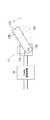
図1は、第1の実施形態である電子内視鏡装置のブロック図である。 FIG. 1 is a block diagram of an electronic endoscope apparatus according to the first embodiment.
電子内視鏡装置は、CCD54を有するビデオスコープ50と、CCD54から読み出される画素信号を処理するとともに光源ユニットが一体的に設けられたプロセッサ10とを備える。ビデオスコープ50はプロセッサ10に着脱自在に接続され、また、被写体像を表示するモニタ52、静止画記録用のレコーダ53とがプロセッサ10に接続される。 The electronic endoscope apparatus includes a
ランプ点灯スイッチ(図示せず)がONになると、ランプ制御部11からランプ12へ電源が供給されてランプ12が点灯する。ランプ12から放射された光は、ロータリシャッタ15、集光レンズ16を介してビデオスコープ50内に設けられたライトガイド51の入射端51Aに入射する。ライトガイド51は、ランプ12から放射される光をビデオスコープ50の先端側へ伝達する光ファイバー束であり、ライトガイド51を通った光は出射端51Bから出射し、拡散レンズである配光レンズ(図示せず)を介して観察部位に光が照射する。 When a lamp lighting switch (not shown) is turned on, power is supplied from the
観察部位において反射した光は対物レンズ(図示せず)を介してCCD54に到達し、観察部位の像がCCD54の受光面に形成される。本実施形態では、カラー撮像方式として単板同時式、色差線順次方式が適用されており、CCDの受光面上にはイエロー(Ye)、シアン(Cy)、マゼンタ(Mg)、グリーン(G)の色要素が市松状に並べられた補色カラーフィルタ(図示せず)が受光面の各画素に対応するよう配置されている。CCD54では、補色カラーフィルタを通る色に応じた被写体像の画素信号が光電変換により発生する。CCD54は、ここではインターライン転送型CCDが適用されている。 The light reflected at the observation site reaches the
カラーテレビジョン方式として例えばNTSC方式が適用されており、動画像をモニタ52に表示させる場合、フィールド読み出しが行われ、CCDドライバ59から送られてくる駆動信号に従って、1/60秒時間間隔ごとに隣接する画素が互いに加算された状態で奇数フィールド、偶数フィールドの画像信号が順次読み出され、増幅回路55へ送られる。 For example, the NTSC system is applied as a color television system, and when a moving image is displayed on the
増幅回路55では、画素信号に対して増幅処理等が施され、画像素信号として初期信号処理回路57へ送られる。初期信号処理回路57では、画像信号に対し所定の処理が施され、プロセッサ10のプロセッサ側信号処理回路28へ送られる。 In the
プロセッサ側信号処理回路28では、初期信号処理回路57から送られてくる画像信号に対し、ホワイトバランス調整、ガンマ補正など様々な処理が施され、一時的に画像メモリ29にデータとして格納される。そして、所定のタイミングで画像信号が順次出力され、モニタ52へ出力される。これにより、観察画像が動画像としてモニタ52に表示される。 The processor-side signal processing circuit 28 performs various processes such as white balance adjustment and gamma correction on the image signal sent from the initial
一方、フリーズボタン53Aの押下によって静止画像をモニタ52に表示、あるいは外部の記録装置へ記録させる場合、同一露光による1フレーム分の画素信号が読み出されるフレーム読み出しが行われる。すなわち、1回の露光で各画素に電荷が蓄積されると、CCD54の画素配列において奇数ラインの画素信号、次いで偶数ラインの画素信号が1フィールド分の画素信号として順番に読み出される。1フィールド分の奇数ライン、偶数ラインの画素信号はそれぞれ初期信号処理回路57、プロセッサ側信号処理回路28へ送られ、奇数フィールドの画像信号、偶数フィールドの画像信号としてモニタ52へ出力される。また、1フィールド分の奇数ライン、偶数ラインの画素信号は、所定の処理が施された後、静止画像データとしてレコーダ53へ送られる。 On the other hand, when a still image is displayed on the
CPUを含むシステムコントロール回路22は、プロセッサ10の動作を制御し、ランプ制御部11、プロセッサ側信号処理回路28などの各回路に制御信号を出力する。プロセッサ側のタイミングコントロール回路(図示せず)では、信号の処理タイミングを調整するクロックパルス信号がプロセッサ10内の各回路に出力され、また、ビデオ信号に付随される同期信号がプロセッサ側信号処理回路28へ送られる。システムコントロール回路22は、各クロックパルス信号の出力タイミングを制御可能であり、フリーズボタン53Aの操作に応じて画像メモリ29に出力されるデータ更新用クロックパルス信号の出力タイミング、CCDドライバ59から出力される駆動用クロックパルス信号などを調整する。 A system control circuit 22 including a CPU controls the operation of the
ビデオスコープ50には、ビデオスコープ50を制御するスコープコントローラ56が設けられており、初期信号処理回路57、タイミングコントロール回路58を制御する。タイミングコントロール回路58は、スコープコントローラ56から送られてくる制御信号に基づいてCCDドライバ59に駆動信号を出力し、CCD54の画素信号読み出し処理を制御する。ビデオスコープ50がプロセッサ10に接続されると、スコープコントローラ56とシステムコントロール回路22との間でデータが送受信される。 The
ロータリシャッタ15はモータ(図示せず)に取り付けられており、モータドライバ23から送られてくる駆動信号に基づいて一定速度で回転する。ロータリシャッタ15と集光レンズ16との間には、遮光用のチョッパ17が設けられており、DCソレノイドによって構成されている。チョッパ17は、PWM駆動回路24から送られてくる一連のパルス信号に基づいて動作する。 The
図2は、ロータリシャッタ15の平面図である。図3は、チョッパ17の平面図である。 FIG. 2 is a plan view of the
ロータリシャッタ15では、照明光を透過する開口部15Aと照明光を遮断する遮光部15Bによって半円部15Pが構成されており、半円部15Pは1フィールド期間(NTSC方式では1/60秒)に対応する。ロータリシャッタ15は、1フレーム読み出し期間(NTSC方式では1/30秒)で一回転し、ランプ12から放射される照明光の光路LB上に開口部15A、遮光部15Bが順番に通過する。その結果、遮光、光透過が1フレーム読み出し期間に渡って2回繰り返される。開口部15Aのサイズは露光時間(電荷蓄積時間)に応じて定められ、これにより電子シャッタと同様に観察画像の明るさ調整が行われる。 In the
静止画像を記録する場合、一方の開口部15Aを通った照明光により得られる(同一露光により得られる)1フレーム分の全画素信号が、1フレーム期間(NTSC方式では1/30秒)かけて読み出される。1フィールド読み出し期間(NTSC方式では1/60秒)でロータリシャッタ15が半周することから、照明光の光路上に他方の開口部15Aが移動してきたとき、開口部15Aを遮蔽して照明光を遮断する必要がある。そのため、チョッパ17が開口部15Aを覆うように動作する。図3では、チョッパ17の退避位置が実線で表されており、開口部15Aを覆う遮光位置は破線によって表されている。 When a still image is recorded, all pixel signals for one frame obtained by illumination light passing through one
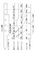
図4は、静止画記録処理を示したタイミングチャートである。 FIG. 4 is a timing chart showing still image recording processing.
フリーズボタン53Aが押下される前の状態では、画素混合読み出し方式によって奇数フィールド、偶数フィールドに応じた画素信号が交互に1/60秒間隔で読み出される。CCD54はインターライン型CCDであることから、ある所定の露光タイミングにおいて蓄積された電荷信号は、次の露光タイミングの期間に読み出される。例えば、n−1番目の露光タイミングにより蓄積される偶数フィールドに応じた混合画素信号は、n番目の露光タイミングの期間に出力される。 In a state before the
フリーズボタン53Aが押下されて静止画記録処理が実行開始されると、同一露光による全画素信号を2フィールド期間に渡って読み出すため、n番目の露光タイミングにおいて蓄積された全画素信号は、奇数ラインの画素信号、偶数ラインの画素信号に分けられて順番に読み出される。この間、遮光するためにチョッパ17が作動する。 When the
さらに、静止画記録処理が実行開始されると、メモリ29に対する画像データ更新用クロックパルス信号のタイミングは、1フィールド期間から1フレーム期間に変更される。これにより、奇数フィールドの画素信号、あるいは偶数フィールドの画素信号がそれぞれ2フィールド期間(1フレーム期間)に渡って使用され、偶数フィールド、奇数フィールドの画素信号によってそれぞれ1/30秒間ずつ動画像が表示される。そして、静止画記録処理が終了すると、メモリ29に対するクロックパルス信号のタイミングは、1フィールド期間へ戻る。 Further, when the execution of the still image recording process is started, the timing of the image data update clock pulse signal for the
このように本実施形態によれば、プロセッサ10内にロータリシャッタ15とチョッパ17とが設けられ、ロータリシャッタ15が1フレーム期間で一回転するように回転する。そして、静止画を記録、表示する場合、メモリ29における画像信号を更新するタイミングが、1フィールド期間から2フィールド期間に変更される。これにより、奇数ラインの画素信号、偶数ラインの画素信号が読み出される2フィールド期間においても観察画像が表示される。 As described above, according to the present embodiment, the
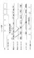
次に図5を用いて、第2の実施形態である電子内視鏡装置について説明する。第2の実施形態では、静止画記録のため露光している間、メモリにおけるデータ更新を行わない。それ以外の構成については、第1の実施形態と実質的に同じである。 Next, an electronic endoscope apparatus according to the second embodiment will be described with reference to FIG. In the second embodiment, data is not updated in the memory during exposure for still image recording. About another structure, it is substantially the same as 1st Embodiment.
図5は、第2の実施形態における静止画記録処理を示したタイミングチャートである。 FIG. 5 is a timing chart showing still image recording processing in the second embodiment.
図5に示すように、静止画を記録、表示する場合、2フィールド期間に渡ってメモリ29におけるデータ更新用クロックパルス信号が送られない。そして、静止画記録用の露光タイミングにおける直前の露光タイミングにおいて蓄積された奇数フィールドの画素信号に基いて、動画像が表示される。 As shown in FIG. 5, when a still image is recorded and displayed, the data update clock pulse signal in the
10 プロセッサ
22 システムコントロール回路
29 画像メモリ(メモリ)
50 ビデオスコープ
54 CCD(撮像素子)
10 Processor 22
50
Claims (5)
Translated fromJapanese被写体を照明するための照明光を射出する光源と、
前記撮像素子から、奇数フィールドに応じた奇数フィールド画素信号、偶数フィールドに応じた偶数フィールド画素信号を順に読み出す動画処理手段と、
前記撮像素子から同一露光により得られた1フレーム分の全画素信号を2フィールド期間に渡って読み出し、2フィールド期間のうち後のフィールド期間において照明光を遮断する静止画処理手段と、
前記動画処理手段と前記静止画処理手段の実行を切り替える切り替え手段と、
静止画処理手段により全画素信号を2フィールド期間に渡って読み出す間、前記静止画記録用の露光タイミング前の前記動画処理手段により得られる奇数フィールド画素信号、偶数フィールド画素信号のうち少なくとも一方の画素信号に基いて、観察画像を表示する暫定画像表示手段と
を備えたことを特徴とする電子内視鏡装置。An electronic endoscope apparatus including a video scope having an image sensor,
A light source that emits illumination light to illuminate the subject;
Movie processing means for sequentially reading out odd field pixel signals corresponding to odd fields and even field pixel signals corresponding to even fields from the imaging device;
A still image processing means for reading out all pixel signals for one frame obtained by the same exposure from the image sensor over a two-field period, and blocking illumination light in a later field period of the two-field period;
Switching means for switching execution of the moving image processing means and the still image processing means;
At least one of the odd field pixel signal and the even field pixel signal obtained by the moving image processing means before the exposure timing for the still image recording while all the pixel signals are read out over two field periods by the still image processing means. An electronic endoscope apparatus comprising: provisional image display means for displaying an observation image based on a signal.
1フィールド分の画素信号を一時的にデータとして前記メモリに格納し、1フィールド期間経過する度に格納されているデータを更新するメモリ更新手段とをさらに有し、
前記暫定画像表示手段が、前記静止画記録用の露光タイミング直前から前記メモリにおけるデータ更新を2フィールド期間に変更することを特徴とする請求項1に記載の電子内視鏡装置。Memory,
Memory update means for temporarily storing pixel signals for one field in the memory as data, and updating the stored data every time one field period elapses;
2. The electronic endoscope apparatus according to claim 1, wherein the temporary image display means changes data update in the memory to a two-field period immediately before the exposure timing for recording the still image.
1フィールド分の画素信号を一時的にデータとして前記メモリに格納し、1フィールド期間経過する度に格納されているデータを更新するメモリ更新手段とをさらに有し、
前記暫定画像表示手段が、前記静止画処理手段により2フィールド期間に渡って全画素信号が読み出される間、前記メモリにおけるデータ更新を停止することを特徴とする請求項1に記載の電子内視鏡装置。Memory,
Memory update means for temporarily storing pixel signals for one field in the memory as data, and updating the stored data every time one field period elapses;
2. The electronic endoscope according to claim 1, wherein the provisional image display unit stops updating data in the memory while all the pixel signals are read out over a two-field period by the still image processing unit. apparatus.
前記撮像素子から同一露光により得られた1フレーム分の全画素信号を2フィールド期間に渡って読み出し、2フィールド期間のうち後のフィールド期間において照明光を遮断する静止画処理手段と、
前記動画処理手段と前記静止画処理手段の実行を切り替える切り替え手段と、
静止画処理手段により全画素信号を2フィールド期間に渡って読み出す間、前記静止画記録用の露光タイミング前の前記動画処理手段により得られる奇数フィールド画素信号、偶数フィールド画素信号のうち少なくとも一方の画素信号に基いて、観察画像を表示する処理を実行する信号処理手段と
を備えたことを特徴とする内視鏡用画像処理装置。
A moving image processing means for sequentially reading out an odd field pixel signal corresponding to an odd field and an even field pixel signal corresponding to an even field from an imaging device of a videoscope;
A still image processing means for reading out all pixel signals for one frame obtained by the same exposure from the image sensor over a two-field period, and blocking illumination light in a later field period of the two-field period;
Switching means for switching execution of the moving image processing means and the still image processing means;
At least one of the odd field pixel signal and the even field pixel signal obtained by the moving image processing means before the exposure timing for the still image recording while all the pixel signals are read out over two field periods by the still image processing means. An endoscope image processing apparatus comprising: signal processing means for executing processing for displaying an observation image based on a signal.
Priority Applications (4)
| Application Number | Priority Date | Filing Date | Title |
|---|---|---|---|
| JP2005056979AJP4786915B2 (en) | 2005-03-02 | 2005-03-02 | Electronic endoscope device |
| FR0601818AFR2882883B1 (en) | 2005-03-02 | 2006-03-01 | ELECTRONIC ENDOSCOPE AND APPARATUS FOR DISPLAYING AN IMAGE USING THE SAME |
| US11/365,506US7907170B2 (en) | 2005-03-02 | 2006-03-02 | Electronic endoscope |
| DE102006009720ADE102006009720A1 (en) | 2005-03-02 | 2006-03-02 | Electronic endoscope |
Applications Claiming Priority (1)
| Application Number | Priority Date | Filing Date | Title |
|---|---|---|---|
| JP2005056979AJP4786915B2 (en) | 2005-03-02 | 2005-03-02 | Electronic endoscope device |
Publications (2)
| Publication Number | Publication Date |
|---|---|
| JP2006239052Atrue JP2006239052A (en) | 2006-09-14 |
| JP4786915B2 JP4786915B2 (en) | 2011-10-05 |
Family
ID=36922037
Family Applications (1)
| Application Number | Title | Priority Date | Filing Date |
|---|---|---|---|
| JP2005056979AExpired - Fee RelatedJP4786915B2 (en) | 2005-03-02 | 2005-03-02 | Electronic endoscope device |
Country Status (4)
| Country | Link |
|---|---|
| US (1) | US7907170B2 (en) |
| JP (1) | JP4786915B2 (en) |
| DE (1) | DE102006009720A1 (en) |
| FR (1) | FR2882883B1 (en) |
Cited By (2)
| Publication number | Priority date | Publication date | Assignee | Title |
|---|---|---|---|---|
| JP2009100916A (en)* | 2007-10-23 | 2009-05-14 | Hoya Corp | Endoscopic system control unit and endoscopic system |
| JP2012125502A (en)* | 2010-12-17 | 2012-07-05 | Hoya Corp | Endoscope processor |
Families Citing this family (38)
| Publication number | Priority date | Publication date | Assignee | Title |
|---|---|---|---|---|
| JP4827398B2 (en)* | 2004-10-15 | 2011-11-30 | Hoya株式会社 | Electronic endoscope apparatus provided with light shielding member |
| JP4953759B2 (en)* | 2006-10-27 | 2012-06-13 | Hoya株式会社 | Electronic endoscope device |
| JP5435916B2 (en) | 2008-09-18 | 2014-03-05 | 富士フイルム株式会社 | Electronic endoscope system |
| US12137873B2 (en) | 2009-06-18 | 2024-11-12 | Endochoice, Inc. | Compact multi-viewing element endoscope system |
| WO2010146587A1 (en) | 2009-06-18 | 2010-12-23 | Peer Medical Ltd. | Multi-camera endoscope |
| US9706903B2 (en) | 2009-06-18 | 2017-07-18 | Endochoice, Inc. | Multiple viewing elements endoscope system with modular imaging units |
| US11278190B2 (en) | 2009-06-18 | 2022-03-22 | Endochoice, Inc. | Multi-viewing element endoscope |
| US9642513B2 (en) | 2009-06-18 | 2017-05-09 | Endochoice Inc. | Compact multi-viewing element endoscope system |
| US9713417B2 (en) | 2009-06-18 | 2017-07-25 | Endochoice, Inc. | Image capture assembly for use in a multi-viewing elements endoscope |
| US11864734B2 (en) | 2009-06-18 | 2024-01-09 | Endochoice, Inc. | Multi-camera endoscope |
| US9101268B2 (en) | 2009-06-18 | 2015-08-11 | Endochoice Innovation Center Ltd. | Multi-camera endoscope |
| US11547275B2 (en) | 2009-06-18 | 2023-01-10 | Endochoice, Inc. | Compact multi-viewing element endoscope system |
| US9101287B2 (en) | 2011-03-07 | 2015-08-11 | Endochoice Innovation Center Ltd. | Multi camera endoscope assembly having multiple working channels |
| US9872609B2 (en) | 2009-06-18 | 2018-01-23 | Endochoice Innovation Center Ltd. | Multi-camera endoscope |
| US9492063B2 (en) | 2009-06-18 | 2016-11-15 | Endochoice Innovation Center Ltd. | Multi-viewing element endoscope |
| US9402533B2 (en) | 2011-03-07 | 2016-08-02 | Endochoice Innovation Center Ltd. | Endoscope circuit board assembly |
| US10165929B2 (en) | 2009-06-18 | 2019-01-01 | Endochoice, Inc. | Compact multi-viewing element endoscope system |
| US8926502B2 (en) | 2011-03-07 | 2015-01-06 | Endochoice, Inc. | Multi camera endoscope having a side service channel |
| US9901244B2 (en) | 2009-06-18 | 2018-02-27 | Endochoice, Inc. | Circuit board assembly of a multiple viewing elements endoscope |
| JP5375359B2 (en)* | 2009-06-22 | 2013-12-25 | ソニー株式会社 | Imaging device, charge readout method, and imaging apparatus |
| US12220105B2 (en) | 2010-06-16 | 2025-02-11 | Endochoice, Inc. | Circuit board assembly of a multiple viewing elements endoscope |
| EP2618718B1 (en) | 2010-09-20 | 2020-04-15 | EndoChoice Innovation Center Ltd. | Multi-camera endoscope having fluid channels |
| US9560953B2 (en) | 2010-09-20 | 2017-02-07 | Endochoice, Inc. | Operational interface in a multi-viewing element endoscope |
| CN103403605A (en) | 2010-10-28 | 2013-11-20 | 恩多巧爱思创新中心有限公司 | Optical systems for multi-sensor endoscopes |
| US12204087B2 (en) | 2010-10-28 | 2025-01-21 | Endochoice, Inc. | Optical systems for multi-sensor endoscopes |
| US9320419B2 (en) | 2010-12-09 | 2016-04-26 | Endochoice Innovation Center Ltd. | Fluid channeling component of a multi-camera endoscope |
| CN107361721B (en) | 2010-12-09 | 2019-06-18 | 恩多巧爱思创新中心有限公司 | Flexible electronic circuit boards for multi-camera endoscopes |
| US11889986B2 (en) | 2010-12-09 | 2024-02-06 | Endochoice, Inc. | Flexible electronic circuit board for a multi-camera endoscope |
| EP2672878B1 (en) | 2011-02-07 | 2017-11-22 | Endochoice Innovation Center Ltd. | Multi-element cover for a multi-camera endoscope |
| JP2013048694A (en)* | 2011-08-30 | 2013-03-14 | Olympus Corp | Endoscope apparatus |
| KR101817655B1 (en)* | 2011-11-07 | 2018-01-12 | 삼성전자주식회사 | Photographing apparatus and method for three dimensional image |
| CA2798716A1 (en) | 2011-12-13 | 2013-06-13 | Peermedical Ltd. | Removable tip endoscope |
| EP2604172B1 (en) | 2011-12-13 | 2015-08-12 | EndoChoice Innovation Center Ltd. | Rotatable connector for an endoscope |
| US9560954B2 (en) | 2012-07-24 | 2017-02-07 | Endochoice, Inc. | Connector for use with endoscope |
| US9993142B2 (en) | 2013-03-28 | 2018-06-12 | Endochoice, Inc. | Fluid distribution device for a multiple viewing elements endoscope |
| US9986899B2 (en) | 2013-03-28 | 2018-06-05 | Endochoice, Inc. | Manifold for a multiple viewing elements endoscope |
| US10499794B2 (en) | 2013-05-09 | 2019-12-10 | Endochoice, Inc. | Operational interface in a multi-viewing element endoscope |
| JP6672006B2 (en)* | 2016-02-18 | 2020-03-25 | オリンパス株式会社 | Imaging device |
Citations (13)
| Publication number | Priority date | Publication date | Assignee | Title |
|---|---|---|---|---|
| JPS62201411A (en)* | 1986-02-28 | 1987-09-05 | Toshiba Corp | endoscope equipment |
| JPH01107732A (en)* | 1987-10-20 | 1989-04-25 | Olympus Optical Co Ltd | Electronic endoscopic apparatus |
| JPH06254045A (en)* | 1993-03-08 | 1994-09-13 | Fuji Photo Optical Co Ltd | Electronic endoscope device |
| JPH0990244A (en)* | 1995-09-19 | 1997-04-04 | Fuji Photo Optical Co Ltd | Electronic endoscope device |
| JPH1085175A (en)* | 1996-09-17 | 1998-04-07 | Fuji Photo Optical Co Ltd | Electronic endoscope system provided with electronic shutter function |
| JPH11216107A (en)* | 1998-01-30 | 1999-08-10 | Fuji Photo Optical Co Ltd | Electronic endoscope unit |
| JPH11216109A (en)* | 1998-02-04 | 1999-08-10 | Fuji Photo Optical Co Ltd | Electronic endoscope unit |
| JPH11216108A (en)* | 1998-01-30 | 1999-08-10 | Fuji Photo Optical Co Ltd | Electronic endoscope unit |
| JPH11225955A (en)* | 1998-02-18 | 1999-08-24 | Fuji Photo Optical Co Ltd | Electronic endoscope device |
| JP2001045473A (en)* | 1999-08-03 | 2001-02-16 | Fuji Photo Optical Co Ltd | Electronic endoscope device |
| JP2002051977A (en)* | 2000-08-10 | 2002-02-19 | Asahi Optical Co Ltd | Switchable electronic endoscope between normal light and special wavelength light |
| JP2003008948A (en)* | 2001-06-22 | 2003-01-10 | Fuji Photo Film Co Ltd | Electronic camera and its image display method, and image recording method |
| JP3370871B2 (en)* | 1996-10-23 | 2003-01-27 | 富士写真光機株式会社 | Electronic endoscope device |
Family Cites Families (12)
| Publication number | Priority date | Publication date | Assignee | Title |
|---|---|---|---|---|
| US82845A (en)* | 1868-10-06 | Improvem ent in saw-sets | ||
| US59722A (en)* | 1866-11-13 | Improvement in the manufacture of wash-boilers, kettles | ||
| US220447A (en)* | 1879-10-07 | Improvement in machines for making fluted trimmings | ||
| JPH0638134B2 (en) | 1985-12-28 | 1994-05-18 | 株式会社町田製作所 | Illumination light supply device used for electronic endoscope device |
| JP3097014B2 (en)* | 1993-07-08 | 2000-10-10 | 株式会社リコー | Electronic still camera |
| US6078353A (en) | 1996-09-12 | 2000-06-20 | Fuji Photo Optical Co., Ltd. | All-pixels reading type electronic endoscope apparatus |
| JP3944954B2 (en)* | 1997-06-16 | 2007-07-18 | ヤマハ株式会社 | Interlaced image still image processing device |
| JP3637264B2 (en) | 2000-05-31 | 2005-04-13 | ペンタックス株式会社 | Endoscope light source device |
| JP3880351B2 (en)* | 2001-09-21 | 2007-02-14 | フジノン株式会社 | Electronic endoscope device for driving a light shielding plate |
| JP4160883B2 (en)* | 2003-09-02 | 2008-10-08 | 富士フイルム株式会社 | Image recording apparatus and image recording method |
| US7336894B2 (en) | 2004-03-31 | 2008-02-26 | Pentax Corporation | Electronic endoscope system, lighting device for electronic endoscope system, and light controller for electronic endoscope system |
| JP4827398B2 (en) | 2004-10-15 | 2011-11-30 | Hoya株式会社 | Electronic endoscope apparatus provided with light shielding member |
- 2005
- 2005-03-02JPJP2005056979Apatent/JP4786915B2/ennot_activeExpired - Fee Related
- 2006
- 2006-03-01FRFR0601818Apatent/FR2882883B1/ennot_activeExpired - Fee Related
- 2006-03-02USUS11/365,506patent/US7907170B2/ennot_activeExpired - Fee Related
- 2006-03-02DEDE102006009720Apatent/DE102006009720A1/ennot_activeWithdrawn
Patent Citations (13)
| Publication number | Priority date | Publication date | Assignee | Title |
|---|---|---|---|---|
| JPS62201411A (en)* | 1986-02-28 | 1987-09-05 | Toshiba Corp | endoscope equipment |
| JPH01107732A (en)* | 1987-10-20 | 1989-04-25 | Olympus Optical Co Ltd | Electronic endoscopic apparatus |
| JPH06254045A (en)* | 1993-03-08 | 1994-09-13 | Fuji Photo Optical Co Ltd | Electronic endoscope device |
| JPH0990244A (en)* | 1995-09-19 | 1997-04-04 | Fuji Photo Optical Co Ltd | Electronic endoscope device |
| JPH1085175A (en)* | 1996-09-17 | 1998-04-07 | Fuji Photo Optical Co Ltd | Electronic endoscope system provided with electronic shutter function |
| JP3370871B2 (en)* | 1996-10-23 | 2003-01-27 | 富士写真光機株式会社 | Electronic endoscope device |
| JPH11216107A (en)* | 1998-01-30 | 1999-08-10 | Fuji Photo Optical Co Ltd | Electronic endoscope unit |
| JPH11216108A (en)* | 1998-01-30 | 1999-08-10 | Fuji Photo Optical Co Ltd | Electronic endoscope unit |
| JPH11216109A (en)* | 1998-02-04 | 1999-08-10 | Fuji Photo Optical Co Ltd | Electronic endoscope unit |
| JPH11225955A (en)* | 1998-02-18 | 1999-08-24 | Fuji Photo Optical Co Ltd | Electronic endoscope device |
| JP2001045473A (en)* | 1999-08-03 | 2001-02-16 | Fuji Photo Optical Co Ltd | Electronic endoscope device |
| JP2002051977A (en)* | 2000-08-10 | 2002-02-19 | Asahi Optical Co Ltd | Switchable electronic endoscope between normal light and special wavelength light |
| JP2003008948A (en)* | 2001-06-22 | 2003-01-10 | Fuji Photo Film Co Ltd | Electronic camera and its image display method, and image recording method |
Cited By (2)
| Publication number | Priority date | Publication date | Assignee | Title |
|---|---|---|---|---|
| JP2009100916A (en)* | 2007-10-23 | 2009-05-14 | Hoya Corp | Endoscopic system control unit and endoscopic system |
| JP2012125502A (en)* | 2010-12-17 | 2012-07-05 | Hoya Corp | Endoscope processor |
Also Published As
| Publication number | Publication date |
|---|---|
| DE102006009720A1 (en) | 2006-09-21 |
| FR2882883B1 (en) | 2011-04-15 |
| US7907170B2 (en) | 2011-03-15 |
| FR2882883A1 (en) | 2006-09-08 |
| US20060198620A1 (en) | 2006-09-07 |
| JP4786915B2 (en) | 2011-10-05 |
Similar Documents
| Publication | Publication Date | Title |
|---|---|---|
| JP4786915B2 (en) | Electronic endoscope device | |
| JP5698878B2 (en) | Endoscope device | |
| US8823789B2 (en) | Imaging apparatus | |
| JP2004313523A (en) | Solid-state imaging device, electronic endoscope | |
| JP4827398B2 (en) | Electronic endoscope apparatus provided with light shielding member | |
| JP2007029746A (en) | Endoscope apparatus | |
| JP2008113177A (en) | Electronic endoscope device | |
| JP7610343B2 (en) | Electronic Endoscope System | |
| JP2008104614A (en) | Endoscope device with automatic light control function | |
| JP2007054113A (en) | Electronic endoscope, endoscope light source device, endoscope processor, and endoscope system | |
| JP4953759B2 (en) | Electronic endoscope device | |
| JP2008110004A (en) | Electronic endoscope device | |
| JP2001211448A (en) | Endoscope system | |
| JP3940016B2 (en) | Electronic endoscope device capable of recording still images | |
| JP4024632B2 (en) | Electronic endoscope device capable of recording still images | |
| JP4439245B2 (en) | Electronic endoscope device | |
| JP4459549B2 (en) | Solid-state imaging device, electronic endoscope, and electronic endoscope apparatus | |
| JP4360813B2 (en) | Electronic endoscope device | |
| JP2011087826A (en) | Imaging apparatus and electronic endoscope apparatus | |
| JP3398551B2 (en) | All-pixel readout electronic endoscope | |
| JP3836593B2 (en) | Electronic endoscope device | |
| JP3898973B2 (en) | Electronic endoscope device capable of recording still images | |
| JP3182415B2 (en) | Imaging device | |
| JP2981437B2 (en) | Light source device for endoscope | |
| JP5186177B2 (en) | Endoscope system control unit and endoscope system |
Legal Events
| Date | Code | Title | Description |
|---|---|---|---|
| A621 | Written request for application examination | Free format text:JAPANESE INTERMEDIATE CODE: A621 Effective date:20080213 | |
| A711 | Notification of change in applicant | Free format text:JAPANESE INTERMEDIATE CODE: A712 Effective date:20080501 | |
| A977 | Report on retrieval | Free format text:JAPANESE INTERMEDIATE CODE: A971007 Effective date:20100812 | |
| A131 | Notification of reasons for refusal | Free format text:JAPANESE INTERMEDIATE CODE: A131 Effective date:20100817 | |
| A521 | Request for written amendment filed | Free format text:JAPANESE INTERMEDIATE CODE: A523 Effective date:20101014 | |
| TRDD | Decision of grant or rejection written | ||
| A01 | Written decision to grant a patent or to grant a registration (utility model) | Free format text:JAPANESE INTERMEDIATE CODE: A01 Effective date:20110628 | |
| A01 | Written decision to grant a patent or to grant a registration (utility model) | Free format text:JAPANESE INTERMEDIATE CODE: A01 | |
| A61 | First payment of annual fees (during grant procedure) | Free format text:JAPANESE INTERMEDIATE CODE: A61 Effective date:20110714 | |
| R150 | Certificate of patent or registration of utility model | Free format text:JAPANESE INTERMEDIATE CODE: R150 | |
| FPAY | Renewal fee payment (event date is renewal date of database) | Free format text:PAYMENT UNTIL: 20140722 Year of fee payment:3 | |
| R250 | Receipt of annual fees | Free format text:JAPANESE INTERMEDIATE CODE: R250 | |
| S531 | Written request for registration of change of domicile | Free format text:JAPANESE INTERMEDIATE CODE: R313531 | |
| R350 | Written notification of registration of transfer | Free format text:JAPANESE INTERMEDIATE CODE: R350 | |
| R250 | Receipt of annual fees | Free format text:JAPANESE INTERMEDIATE CODE: R250 | |
| LAPS | Cancellation because of no payment of annual fees |