JP2006238900A - Blood vessel position marking device - Google Patents
Blood vessel position marking deviceDownload PDFInfo
- Publication number
- JP2006238900A JP2006238900AJP2005028376AJP2005028376AJP2006238900AJP 2006238900 AJP2006238900 AJP 2006238900AJP 2005028376 AJP2005028376 AJP 2005028376AJP 2005028376 AJP2005028376 AJP 2005028376AJP 2006238900 AJP2006238900 AJP 2006238900A
- Authority
- JP
- Japan
- Prior art keywords
- light
- blood vessel
- light guide
- suction tube
- suction
- Prior art date
- Legal status (The legal status is an assumption and is not a legal conclusion. Google has not performed a legal analysis and makes no representation as to the accuracy of the status listed.)
- Pending
Links
- 210000004204blood vesselAnatomy0.000titleclaimsabstractdescription74
- 238000001514detection methodMethods0.000claimsabstractdescription24
- 230000003287optical effectEffects0.000claimsabstractdescription14
- 238000005192partitionMethods0.000claimsabstractdescription10
- 239000013307optical fiberSubstances0.000claimsdescription27
- 210000004369bloodAnatomy0.000claimsdescription8
- 239000008280bloodSubstances0.000claimsdescription8
- 238000012544monitoring processMethods0.000claimsdescription6
- 206010033675panniculitisDiseases0.000claimsdescription6
- 210000004304subcutaneous tissueAnatomy0.000claimsdescription6
- 210000003491skinAnatomy0.000description31
- 239000007788liquidSubstances0.000description13
- 238000002347injectionMethods0.000description12
- 239000007924injectionSubstances0.000description12
- 238000001802infusionMethods0.000description5
- 238000000034methodMethods0.000description5
- 239000000049pigmentSubstances0.000description5
- 239000000306componentSubstances0.000description4
- 108010054147HemoglobinsProteins0.000description3
- 102000001554HemoglobinsHuman genes0.000description3
- QVGXLLKOCUKJST-UHFFFAOYSA-Natomic oxygenChemical compound[O]QVGXLLKOCUKJST-UHFFFAOYSA-N0.000description3
- 229910052760oxygenInorganic materials0.000description3
- 239000001301oxygenSubstances0.000description3
- 230000005540biological transmissionEffects0.000description2
- 238000003780insertionMethods0.000description2
- 230000037431insertionEffects0.000description2
- 210000001519tissueAnatomy0.000description2
- LFQSCWFLJHTTHZ-UHFFFAOYSA-NEthanolChemical compoundCCOLFQSCWFLJHTTHZ-UHFFFAOYSA-N0.000description1
- 108010064719OxyhemoglobinsProteins0.000description1
- 206010042496SunburnDiseases0.000description1
- 238000010521absorption reactionMethods0.000description1
- 230000032683agingEffects0.000description1
- 230000017531blood circulationEffects0.000description1
- 239000012503blood componentSubstances0.000description1
- 230000037237body shapeEffects0.000description1
- 238000006243chemical reactionMethods0.000description1
- 239000011248coating agentSubstances0.000description1
- 238000000576coating methodMethods0.000description1
- 210000004207dermisAnatomy0.000description1
- 210000000624ear auricleAnatomy0.000description1
- 238000005516engineering processMethods0.000description1
- 210000002615epidermisAnatomy0.000description1
- 230000001678irradiating effectEffects0.000description1
- 239000010410layerSubstances0.000description1
- 230000031700light absorptionEffects0.000description1
- 239000003550markerSubstances0.000description1
- 238000005259measurementMethods0.000description1
- 230000002250progressing effectEffects0.000description1
- 238000011160researchMethods0.000description1
- 230000000717retained effectEffects0.000description1
- 230000000630rising effectEffects0.000description1
- 210000004872soft tissueAnatomy0.000description1
- 239000002344surface layerSubstances0.000description1
- 210000003462veinAnatomy0.000description1
- 238000012800visualizationMethods0.000description1
- 238000004804windingMethods0.000description1
Images


Classifications
- A—HUMAN NECESSITIES
- A61—MEDICAL OR VETERINARY SCIENCE; HYGIENE
- A61B—DIAGNOSIS; SURGERY; IDENTIFICATION
- A61B5/00—Measuring for diagnostic purposes; Identification of persons
- A61B5/48—Other medical applications
- A61B5/4887—Locating particular structures in or on the body
- A61B5/489—Blood vessels
- A—HUMAN NECESSITIES
- A61—MEDICAL OR VETERINARY SCIENCE; HYGIENE
- A61B—DIAGNOSIS; SURGERY; IDENTIFICATION
- A61B5/00—Measuring for diagnostic purposes; Identification of persons
- A61B5/0059—Measuring for diagnostic purposes; Identification of persons using light, e.g. diagnosis by transillumination, diascopy, fluorescence
- A61B5/0062—Arrangements for scanning
- A61B5/0064—Body surface scanning
Landscapes
- Health & Medical Sciences (AREA)
- Life Sciences & Earth Sciences (AREA)
- Heart & Thoracic Surgery (AREA)
- Medical Informatics (AREA)
- Biophysics (AREA)
- Pathology (AREA)
- Engineering & Computer Science (AREA)
- Biomedical Technology (AREA)
- Vascular Medicine (AREA)
- Physics & Mathematics (AREA)
- Molecular Biology (AREA)
- Surgery (AREA)
- Animal Behavior & Ethology (AREA)
- General Health & Medical Sciences (AREA)
- Public Health (AREA)
- Veterinary Medicine (AREA)
- Infusion, Injection, And Reservoir Apparatuses (AREA)
Abstract
Translated fromJapaneseDescription
Translated fromJapanese本発明は、血管センサにより特定された皮膚表面上の部位に注射針の刺入位置の目安となる目印を付ける装置に関する。 The present invention relates to an apparatus for marking a site on a skin surface specified by a blood vessel sensor, which serves as a guide for an insertion position of an injection needle.
診療のため際医師や看護婦が患者、検診者に注射を行う際に、注射を受ける者の体形、年齢等により血管の位置が確認し難いため、針の抜き刺しを繰り返さざるを得なくなる場合が生ずる。体形的には肥満ぎみで脂肪層が厚い場合、病気でむくみのある人の場合にこのような傾向があり、乳幼児の場合は血管が細い上に皮下組織が厚いのでやはり目視での血管の確認が困難である。注射が円滑になされないことは、入院患者のように日に数回の注射が施される人にとっては、苦痛、ストレスをもたらすことになり、乳幼児の場合、熟練した小児科医でも難渋することがある。
一方で、高齢化社会の到来とともに、在宅医療の取り組みの中で、遠隔操作を含めた自動化の可能性を探る研究も進んでおり、視覚で捉えられない血管の可視化技術へのニーズが高まっている。When a doctor or nurse makes an injection to a patient or examiner for medical treatment, it is difficult to confirm the position of the blood vessel depending on the body shape, age, etc. of the person receiving the injection, so it is necessary to repeat needle insertion and removal Will occur. If the body is obese and the fat layer is thick, there is such a tendency in the case of a sick and swollen person, and in the case of infants, the blood vessels are thin and the subcutaneous tissue is thick, so the blood vessels can be confirmed visually Is difficult. The lack of smooth injections can be painful and stressful for those who are given several injections a day, such as hospitalized patients, and even a pediatrician can be troubled by infants. is there.
On the other hand, with the advent of an aging society, research on the possibility of automation including remote control is also progressing in home medical care efforts, and the need for visualization technology of blood vessels that cannot be grasped visually is increasing. Yes.
血管、血流の検知、測定に関する技術として、脈拍センサ、パルスオキシメータ等がある。脈拍センサは、光源からの照射光のうちの赤外領域成分を血液中のヘモグロビンが吸収することにより、検出器に届く光の赤外領域成分の強度が心拍変動に伴う血管中の血流変化に応じて規則的に変動することを利用して、脈拍をモニターするもので、実用化されているものとして、装置を手指の先端に被せるか挟む形態、あるいは耳朶に挟む形態のような透過型のもの、巻き付け部材で指先に装置を保持固定する形態のような反射型のものがある。また、パルスオキシメータは動脈血中の血液中の酸化ヘモグロビンに注目して酸素飽和度を計測するものであって、光源からの赤色もしくは赤外領域の透過光から、動脈血中の酸素飽和度を求める。透過型のものが実用化されているが、反射型のものは、生体組織内の経路が異なって正確な酸素飽和度の測定ができないという問題があって、実用化されていない。掌の血管パターンを利用することが個人認証の分野で試みられており、これは掌を透過する光の強度を検出するものである。 Techniques relating to detection and measurement of blood vessels and blood flow include pulse sensors and pulse oximeters. The pulse sensor absorbs the infrared region component of the light emitted from the light source, and the hemoglobin in the blood absorbs the intensity of the infrared region component of the light that reaches the detector. The pulse type is monitored by utilizing the regular fluctuation according to the type, and the transmission type such as a mode in which the device is put on or put on the tip of a finger or a mode in which the device is put on the earlobe And a reflection type such as a form in which the device is held and fixed to the fingertip by a winding member. The pulse oximeter measures oxygen saturation by paying attention to oxyhemoglobin in arterial blood, and obtains oxygen saturation in arterial blood from red or infrared transmitted light from a light source. . The transmission type has been put into practical use, but the reflection type has a problem that the path in the living tissue is different and accurate oxygen saturation cannot be measured, and has not been put into practical use. The use of the blood vessel pattern of the palm has been attempted in the field of personal authentication, which detects the intensity of light transmitted through the palm.
ところで、注射や点滴の場合の血管探索の対象部位は一般的に上腕であり、掌や指と異なって肉厚であるため、透過型とすることはできず、反射型のものになる。光や音を検知する血管探索装置として次のような文献に開示されたものがある。 By the way, the target site for blood vessel search in the case of injection or infusion is generally the upper arm and is thick unlike the palm or finger, so it cannot be transmissive, but is reflective. Some blood vessel search devices that detect light and sound are disclosed in the following documents.
特許文献1は、LED等の発光部からの光を照射し体組織、血管等で反射した光を受光部で受け、それによって生じた電流値を指定された閾値と比較し、閾値以下であればランプを点灯することにより血管の位置を特定する技術を開示している。 In Patent Document 1, light received from a light emitting unit such as an LED and reflected by a body tissue, blood vessel, or the like is received by a light receiving unit, and a current value generated thereby is compared with a specified threshold value. For example, a technique for specifying the position of a blood vessel by lighting a lamp is disclosed.
特許文献2は、発光手段とその両側に位置する2つの受光手段とからなる検出手段を複数組一列に配置し、各組ごとに検出手段の2つの受光手段の受光量を比較手段と、2つの受光手段の受光量が同じか異なるかを表示する手段を設けて、静脈の位置及び方向を確認することが開示している。 In
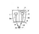
医師が注射や点滴を行う前に、公知の血管検出装置により目的の血管を検出及び確認する過程を、図5に示すような光による反射型の血管検出装置を用いた場合について説明する。医師はアルコール類で該当部位近辺を消毒した後、図5に示すような血管検出装置のセンサ部を皮膚表面に接触あるいは近接させて平面的にスライドさせ、血管位置を検出する。血管検出装置のケーシング4内のLED等の発光素子1から発した光は、光ファイバー5aを通過して皮膚表面6から皮下組織内に浸入する。皮膚内に浸入した透過光9は血管7の内部の血液8に含まれるヘモグロビンにより特定の波長成分が吸収され、反射光10が光ファイバー5bを経てケーシング4内の受光素子2に到達する。 The process of detecting and confirming a target blood vessel with a known blood vessel detection device before a doctor performs injection or infusion will be described in the case of using a reflection type blood vessel detection device as shown in FIG. The doctor disinfects the vicinity of the corresponding site with alcohol, and then slides the sensor portion of the blood vessel detection device as shown in FIG. 5 in contact with or close to the skin surface to detect the blood vessel position. Light emitted from the light emitting element 1 such as an LED in the
ケーシング4内で発光素子1及び光ファイバー5aと、受光素子2及び光ファイバー5bとの間は隔壁3で遮光されている。血管検出装置は受光素子2で受光した光の強度を示す信号のモニター手段11を備えており、血管検出装置を皮膚表面6に沿ってスライドさせながら、反射光の強度をモニターし、血管位置を探索する。反射光は血液の成分による光吸収のために血管の直上と、それ以外の位置とではその強度が異なる。ヘモグロビンの吸収を利用する場合、光源として赤外領域の発光素子が用いられる。光ファイバー5a、5bの先端は離れており、反射光の強度が谷になる位置は、光ファイバー先端間の中心位置の直下に血管が存在することを意味する。 In the
目的の血管位置が特定された後に、その位置に注射を施すのであるが、従来の装置ではこのように探索した血管の位置を適格にマーキングを行う手段が備えられていなかった。血管位置を確認した後、実際に注射する際に装置を腕の血管検出位置から外さなければならず、検出位置に何らかの目印を残さない限り、検出した位置が判然としなくなる。
このようなことから、適格な位置に注射するために、血管検出後に検出位置をマーキングすることが必要になる。文献5には、LEDにより血管位置をマーキングし、あるいは顔料によりマーキングすることが開示されているが、LEDによりマーキングする場合に検出装置を皮膚から外せないので血管位置の検出をする人と注射をする人が同時に作業に携わる必要があり、手間がかかって能率が悪い。また、顔料を付与する場合には皮膚に顔料が長期間残存することになる。After the target blood vessel position is specified, the injection is performed at that position. However, the conventional apparatus has not been provided with means for appropriately marking the searched blood vessel position. After confirming the blood vessel position, the device must be removed from the blood vessel detection position of the arm when actually injecting, and the detected position is unclear unless some mark is left at the detection position.
For this reason, it is necessary to mark the detection position after blood vessel detection in order to inject at an appropriate position. Reference 5 discloses that a blood vessel position is marked with an LED or a pigment. However, when marking with an LED, the detection device cannot be removed from the skin. Need to be involved in the work at the same time, it takes time and is inefficient. In addition, when a pigment is applied, the pigment remains on the skin for a long time.
特許文献3には、血液に吸収される波長の光を断続光にして照射し、血管に断続光が照射されると断続光の周波数に応じた音響信号を発生することを利用して、音響信号を圧電素子で検出して血管位置を特定し、その位置にペン等でマーキングするためのマーク口を備えることについて開示されているが、ペン等でマーキングするために、マーキングの形跡が長期間にわたって残存する。
特許文献4には、光源の光を皮膚面に照射し目視で血管位置を確認し付設された突起状のマーカーを皮膚に押し当てて血管位置をマーキングすることが示されている。しかし、皮膚は軟組織であり、構造的な突起等により皮膚表面に窪みをつける場合、丸みをもった突起等を血管の位置との間に介在する厚みをもち弾力性のある皮下組織に押し込んでいき、また皮膚表面は必ずしも平面状ではなく、ある程度曲率をもつので、表皮及び真皮といった表面に近い層と、対象となる血管がある皮下組織との間でのずれが生じ易く、正確にマーキングができない可能性が大きい。この突起等を先鋭なものにすれば正確さが多少向上するが、痛みが生じ、傷、痕跡を残すことにもなる。 Japanese Patent Application Laid-Open No. H10-228688 shows that the light is emitted from the light source to the skin surface, the blood vessel position is visually confirmed, and the attached marker is pressed against the skin to mark the blood vessel position. However, the skin is soft tissue, and when the skin surface is dented by structural protrusions, etc., push the rounded protrusions etc. into the elastic subcutaneous tissue with a thickness intervening between the positions of the blood vessels. In addition, the skin surface is not necessarily flat, and has a certain degree of curvature. Therefore, there is a tendency for a gap between the surface layer, such as the epidermis and dermis, and the subcutaneous tissue with the target blood vessel to be accurately marked. There is a great possibility that it cannot be done. If the protrusions are sharpened, the accuracy will be improved somewhat, but pain will be generated, leaving scratches and traces.
このように、従来技術による血管位置の検出、マーキングにおいては、血管位置を検出しても、血管位置を簡単な操作で正確にマーキングすることができず、一人の者が血管の位置の特定と、その後の注射、点滴の操作を簡単に行うことができなかった。また、塗布式のマーキングの場合がその痕跡が長期間残存するという問題点があり、突起を押し込む手法では位置ずれによりマーキングが正確になされないとともに、傷、痕跡が残り、痛みを生ずることにもなるものでもあった。 As described above, in the detection and marking of the blood vessel position according to the prior art, even if the blood vessel position is detected, the blood vessel position cannot be accurately marked with a simple operation. The subsequent injection and infusion operations could not be easily performed. In addition, in the case of coating-type marking, there is a problem that the trace remains for a long time, and the method of pushing the projection does not make the marking accurately due to the positional deviation, and the scratch and the trace remain and cause pain. It was also a thing.
本発明は、このような課題を解決するものであり、血液に吸収される成分を含む光を発光する発光素子と、該発光素子からの光を導く第1の導光体と、該第1の導光体から出射し皮膚表面を通り皮下組織で反射した光を導く第2の導光体と、該第2の導光体を通過した光を受光し受光した光の強度を示す信号に変換する受光素子と、該受光素子からの信号を受けて受光した光の強度をモニターするモニター手段とを有する血管検出手段と、前記発光手段と前記受光手段との間に、前記第1の導光体から出る光の光路と前記第2の導光体に向かう光の光路との交点を通る方向に皮膚表面から離れた第1の位置と皮膚表面に当接する第2の位置との間で移動可能に配置された吸引管と、を備え、前記吸引管の前記光路の交点と反対の側に吸引手段を接続して吸引動作により血管位置をマーキングできるようにしたものである。 The present invention solves such a problem, and a light-emitting element that emits light including a component absorbed by blood, a first light guide that guides light from the light-emitting element, and the first A second light guide that guides light emitted from the light guide and passes through the surface of the skin and reflected by the subcutaneous tissue, and a signal that indicates the intensity of the received light after receiving the light that has passed through the second light guide. Between the light emitting means and the light receiving means, a blood vessel detecting means having a light receiving element for conversion and a monitor means for monitoring the intensity of light received in response to a signal from the light receiving element, the first light guide Between a first position away from the skin surface and a second position in contact with the skin surface in a direction passing through the intersection of the optical path of the light emitted from the light body and the optical path of the light toward the second light guide A suction pipe movably arranged, and suction means on a side opposite to the intersection of the optical paths of the suction pipe It is obtained by allowing marking the position of the blood vessel by suction operatively connected.
本発明では、反射型の血管検出装置に吸引管及び吸引手段によるマーキング装置を備えるという簡単な構成により、血管検出装置により特定された血管位置に正確にマーキングを行うことができるものである。また、血管位置のマーキングと、それに続く注射、点滴の作業が一人でも容易にできるようになり、マーキングの痕跡が長時間残存することもない。 In the present invention, it is possible to accurately mark the blood vessel position specified by the blood vessel detection device by a simple configuration in which the reflection type blood vessel detection device is provided with a marking device using a suction tube and suction means. In addition, it becomes possible for one person to easily perform the marking of the blood vessel position and the subsequent injection and infusion work, and the marking trace does not remain for a long time.
以下、発明の実施の形態を、実施例に基づき、図面を参照して説明する。 Hereinafter, embodiments of the present invention will be described based on examples with reference to the drawings.
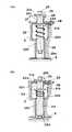
本発明の好ましい実施例を図1に示す。図1に示される血管位置マーキング装置は、図1に示される血管検出装置にマーキング装置20を設けたものである。図5の血管検出装置と同様に、ケーシング4内に設けられたLED等の発光素子1を上から下向きに導く光ファイバー5a、反射光を下から上向きに導く光ファイバー5b、光ファイバー5bを通過した反射光を受光し電気信号に変換する受光素子2、受光素子2からの電気信号により反射光の強度をモニターするための手段(図示せず)を備えている。光ファイバー5aは発光素子1の光を垂直方向下方に導き、光ファイバー5bは反射光を垂直方向に受光素子2に向けて導くものである。ケーシングの下側部分は、光ファイバー5a、5bの先端部を保持するとともに、先端部から光が出入できるようになっている。光ファイバー5a、5bの先端近傍の部分は光の出入の方向を規定することになり、光ファイバー5aから出た光の光路と光ファイバー5bに向かう反射光の光路が交差するように対称的に内方の向きにするのがよい。 A preferred embodiment of the present invention is shown in FIG. The blood vessel position marking device shown in FIG. 1 is obtained by providing a
ケーシング4の内部において、発光素子1及び光ファイバー5aと、受光素子2及び光ファイバー5bとの間に隔壁3が形成されている。隔壁3は発光素子1の側と受光素子2の側との間に光が通過しないように遮光するとともに、マーキング装置20を上下方向に移動可能に支持しガイドする形状になっている。マーキング装置20が隔壁3内に設けられていることのほかは、図1の血管位置マーキング装置は図5の血管検出装置と同様である。 Inside the
図2(a)は図1のマーキング装置の部分を詳細に示したものである。マーキング装置20は、筒体24と、筒体24の内部に内挿され固定保持された吸引管25とを備えており、吸引管25の上端部25b及び下端部25aはそれぞれ筒体24の上端及び下端より突出しており、筒体24の上端に上側ストッパー21aが固設され、それより下方に間隔をおいて下側ストッパー21bが固設されている。このようなマーキング装置20が隔壁3の形状によりガイドされて上下動可能に設けられている。筒体24に内挿された吸引管25の移動方向は光ファイバー5aから出る光の光路と光ファイバー5bに向かう光の光路との交点を通るようにし、この方向に吸引管25が下降して下端部25aが皮膚に当接した位置が血管の存在を示す位置となる。光ファイバー5a、5bを対称的に配置した場合、この方向は対称軸の方向であり、吸引管25の下端部25aが皮膚に当接する位置は光ファイバー5a、5bの先端間の中心の位置となる。 FIG. 2A shows in detail the portion of the marking device of FIG. The marking
ケーシング4の上側の上板22aに上部ガイド孔22cが形成され、隔壁3の下側部分に下部ガイド孔21dが形成されている。下側ガイド孔22dの上側の隔壁3の部分は下側ガイド孔より大径の空間になっており、肩部22bが形成されている。肩部22bと下側ストッパー21bとの間にコイル状ばね23が圧縮状態で設けられていて、通常はコイル状ばね23のばね力により下側ストッパー21bがケーシングの上板22aに達するまで押付けられている。 An
光ファイバー5a、5bを対象形に配置したものでは、筒体24は、これに内挿された吸引管25の中心軸線が光ファイバー5a、5bの対称中心となる位置で垂直方向に上下動するように、上部ガイド孔22cと下部ガイド孔22dとに可動に支持されている。可動筒体24をコイルばね23の力に抗して押し下げたときに、上側ストッパー21aがケーシングの上板22aの上面に接した状態で可動筒体24が停止し、このときに吸引管25の下端部25aが皮膚にマーキングする位置、すなわち光ファイバー5a、5bの下端よりわずかに下に下降して皮膚を軽く押付ける位置になるように、上側ストッパー21aと下側ストッパー21bとの間隔27が設定されている。吸引管25の上端部25bには公知の吸引手段(図示せず)が直接あるいはチューブを介して接続されている。 In the case where the
マーキング装置20は、これをコイルばね23の力に抗して押し下げた状態で吸引によるマーキングを行うものであり、マーキングを行い易くするために、この押し下げた状態で保持するのが望ましい。そのため上側ストッパー21aより下側の筒体24の側部にばねで外方に突出するように押圧されマーキング装置を押し下げた状態でケーシングの上板22aの下面に係止される係止手段28を設け、ケーシング4の側に係止手段28による係止を解除する解除手段29を設けるのがよい。 The marking
吸引管25の内部30を負圧にする吸引手段としては、例えばスポイトが使用できる。負圧の大きさはスポイトの容量の異なるものを適宜付け替えて変えられる。より強い吸引力を得たい場合には、ピペット用のピペッターが用いられる。さらに、注射器の針を除いたものを直接またはチューブを介して接続すれば、より強力に吸引できる。また、チューブを介して電動式の吸引ポンプを接続してもよい。これらの吸引手段は、医療従事者にとって操作性がよいとされるもの、注射の対象者の年齢、性別、体質等により皮膚表面の堅さや色が異なることから、マーキングが明瞭になされる最適な吸引力となるものという見地から適宜選択して使用される。 For example, a syringe can be used as a suction means for making the inside 30 of the
次に、本発明の動作形態について説明する。
本発明の血管位置マーキング装置を用いて血管位置を探索し血管位置にマーキングを行う動作について説明する。血管位置マーキング装置を注射がなされる腕等の部位に近接してスライドさせ、血管位置を探索する過程は、公知の血管検出装置を用いた場合と同様である。モニターされた反射光の強度が谷となる位置で血管位置マーキング装置を停止させ、この位置に保持しながらマーキング操作を行う。反射光の強度が谷になる位置は、その位置を通過して確認できるので、実際には、一旦谷の位置を通過した後に逆向きに戻して確認することが必要になる。Next, the operation mode of the present invention will be described.
An operation of searching for a blood vessel position and marking the blood vessel position using the blood vessel position marking device of the present invention will be described. The process of sliding the blood vessel position marking device in proximity to a site such as an arm to be injected and searching for the blood vessel position is the same as in the case of using a known blood vessel detection device. The blood vessel position marking device is stopped at a position where the intensity of the reflected light that is monitored becomes a valley, and the marking operation is performed while being held at this position. Since the position where the intensity of the reflected light reaches the valley can be confirmed by passing through the position, in practice, it is necessary to confirm by returning to the reverse direction after once passing through the position of the valley.
血管位置マーキング装置を停止させた時に、マーキング装置20は図2(a)に示される状態にあり、下側ストッパー21bがケーシングの上板22aの下面に当接している。マーキングを行うために上側ストッパー21aをそれと一体的な可動筒体24とともにコイル状ばね23の力に抗して押下げていき、上側ストッパー21aがケーシングの上板22aの上面に当接して停止した時に筒体24に内挿された吸引管25の下端部25aが血管のある目標位置となる皮膚の部分を軽く押す状態になっている(図2(b))。この状態で筒体24に設けられた係止手段28がケーシングの上板22aの下面に係止される。 When the blood vessel position marking device is stopped, the marking
この時の吸引管25の下端部25aと皮膚との関係を拡大して示すと、図3(a)のようになっている。状態で吸引管25の上端部25bに接続された吸引装置を動作させて吸引を行うと、吸引管25の下端部25aは皮膚に軽く押付けられていて空気が通過することはないので、吸引管25内部が大気圧に対して負圧になり、図3(b)に示されるように、吸引管25内に位置する皮膚部分が持ち上げられ、丘状の突起32を形成する。このように吸引を行っている状態で、ある程度の時間その負圧を保持する。保持時間は負圧の圧力の程度によって異なるが、容量3mlのスポイトの場合で、約10秒間保持すれば十分である。 FIG. 3A shows an enlarged view of the relationship between the
吸引ポンプを用いた場合、真空度が高いほど短時間で明瞭なマーキングがなされるが、吸引により皮膚表面の局部が過度に持ち上げられると痛みを感じるおそれがあるので、適度な負圧とすべきである。管内が負圧に保たれている限り、皮膚の突起32により吸引管25の下端部25aが目標位置から横方向にずれること防止される。 When using a suction pump, the higher the degree of vacuum, the clearer the marking will be made in a shorter time. However, if the local area of the skin surface is lifted excessively by suction, there is a risk of feeling pain. It is. As long as the inside of the tube is maintained at a negative pressure, the
このようにある程度の時間負圧を保持して丘状の突起32が形成された後に、係止手段28による係止を解除して吸引管を上昇させ、あるいは血管位置マーキング装置全体を外して、吸引管25を皮膚表面から取り外しても、丘状の突起はそのまましばらくの間残存する。この残存時間は吸引の際の負圧の大小により異なるが、注射、点滴を行うまで持続すれば十分である。またその部分の皮膚の色は周辺部分に比べて赤みを帯び、丘状の突起とともに色の違いとしても識別が可能である。 After the hill-shaped
体毛の濃い人などは、吸引管の下端部25aと皮膚との間に体毛が挟まることによって、丘状の突起を形成するのに十分な負圧が発生できない場合がある。また、人種の違いや日焼けの程度により、吸引により生じるはずの赤みが目視で確認できない場合もある。そのような場合に、本発明の吸引によるマーキング装置を用いて色素を含んだ液体を塗布することもできるのであり、それについて説明する。 A person with dark body hair may not be able to generate a negative pressure sufficient to form a hill-shaped protrusion due to the hair being sandwiched between the
筒体24とともに吸引管25を押し下げて係止し、下端部25aを人体に害のない色素を含んだ液体の液面33にわずかに接触させると、図4(a)に示されるように、毛細管現象により微量の液体が管内に取り込まれ、管内の液面34が若干上昇する。そのまま筒体24の係止を解除するか、マーキング装置全体を引き上げると、図4(b)に示されるように、吸引管の下端部25aの内部で上昇した液面に想到する微量の液体35が保持される。このように液体を保持した状態で、前述したように血管を検出した後、筒体24とともに吸引管25を押し下げて皮膚に接触させると、目標の位置に微量液体35を滴下させ塗布することができる。 When the
1 発光素子
2 受光素子
3 隔壁
4 ケーシング
5a 第1の導光体(光ファイバー)
5b 第2の導光体(光ファイバー)
6 皮膚表面
7 血管
8 血液
9 透過光
10 反射光
11 モニター手段
20 マーキング装置
23 コイル状ばね
24 筒体
25 吸引管
28 係止手段
29 解除手段
32 突起
33,34 液面DESCRIPTION OF SYMBOLS 1
5b Second light guide (optical fiber)
6
Claims (4)
Translated fromJapanese前記発光手段と前記受光手段との間に、前記第1の導光体から出る光の光路と前記第2の導光体に向かう光の光路との交点を通る方向に皮膚表面から離れた第1の位置と皮膚表面に当接する第2の位置との間で移動可能に配置された吸引管と、
を備え、前記吸引管の前記光路の交点と反対の側に吸引手段を接続して吸引動作により血管位置をマーキングできるようにしたことを特徴とする血管位置マーキング装置。A light-emitting element that emits light containing a component absorbed by blood, a first light guide that guides light from the light-emitting element, and is emitted from the first light guide and reflected by the subcutaneous tissue through the skin surface A second light guide that guides the transmitted light, a light receiving element that receives the light that has passed through the second light guide and converts the light into a signal indicating the intensity of the received light, and receives a signal from the light receiving element Blood vessel detection means having monitoring means for monitoring the intensity of the received light;
Between the light emitting means and the light receiving means, a first distance away from the skin surface in a direction passing through the intersection of the optical path of the light emitted from the first light guide and the optical path of the light toward the second light guide. A suction tube movably disposed between a first position and a second position in contact with the skin surface;
A blood vessel position marking device, wherein a suction means is connected to a side of the suction tube opposite to the intersection of the optical paths so that the blood vessel position can be marked by a suction operation.
Priority Applications (1)
| Application Number | Priority Date | Filing Date | Title |
|---|---|---|---|
| JP2005028376AJP2006238900A (en) | 2005-02-01 | 2005-02-04 | Blood vessel position marking device |
Applications Claiming Priority (2)
| Application Number | Priority Date | Filing Date | Title |
|---|---|---|---|
| JP2005024851 | 2005-02-01 | ||
| JP2005028376AJP2006238900A (en) | 2005-02-01 | 2005-02-04 | Blood vessel position marking device |
Publications (1)
| Publication Number | Publication Date |
|---|---|
| JP2006238900Atrue JP2006238900A (en) | 2006-09-14 |
Family
ID=37045901
Family Applications (1)
| Application Number | Title | Priority Date | Filing Date |
|---|---|---|---|
| JP2005028376APendingJP2006238900A (en) | 2005-02-01 | 2005-02-04 | Blood vessel position marking device |
Country Status (1)
| Country | Link |
|---|---|
| JP (1) | JP2006238900A (en) |
Cited By (1)
| Publication number | Priority date | Publication date | Assignee | Title |
|---|---|---|---|---|
| CN115054202A (en)* | 2022-06-10 | 2022-09-16 | 郑州航空港经济综合实验区空港人工智能研究院 | Artery identification locator |
- 2005
- 2005-02-04JPJP2005028376Apatent/JP2006238900A/enactivePending
Cited By (1)
| Publication number | Priority date | Publication date | Assignee | Title |
|---|---|---|---|---|
| CN115054202A (en)* | 2022-06-10 | 2022-09-16 | 郑州航空港经济综合实验区空港人工智能研究院 | Artery identification locator |
Similar Documents
| Publication | Publication Date | Title |
|---|---|---|
| US12402816B2 (en) | Medical monitoring device for harmonizing physiological measurements | |
| JP5351419B2 (en) | Blood test apparatus and blood test method | |
| US8287467B2 (en) | Puncturing system | |
| US20170290537A1 (en) | Capillary refill time diagnostic apparatus and methods | |
| US8647575B2 (en) | Device for measuring blood component | |
| TWI310834B (en) | Sensor with integrated lancet | |
| CN100396234C (en) | Detector for measuring biological signal and biological signal measuring system including same | |
| US20090076415A1 (en) | Cap for a Lancing Device | |
| JP2004529728A (en) | Apparatus and method for sampling body fluid | |
| JP2006239114A (en) | Cuff-less electronic blood pressure monitor | |
| KR20030042393A (en) | A disposal lancet | |
| RU2414854C2 (en) | Device for providing constant contact pressure in sampling | |
| JP2017012375A (en) | Blood glucose level measuring device | |
| JP2000232974A (en) | Specimen sampling implement and puncture device | |
| JP2006238900A (en) | Blood vessel position marking device | |
| JP2007181602A (en) | Portable blood sugar level measuring instrument | |
| CN101938941B (en) | Skin incision instrument | |
| JP2011110083A (en) | Skin tissue measuring probe | |
| JP2004290692A (en) | Test device for humor | |
| JP2004290477A (en) | Ingredient measuring device and kit | |
| JP4502634B2 (en) | Puncture device | |
| JP2011062403A (en) | Skin tissue measuring probe | |
| JP2011062402A (en) | Skin tissue measuring probe | |
| MacLean | Development and Testing of a Near Infrared Spectroscopy Opioid Overdose Detection Device | |
| TWM523915U (en) | Walking aid with physiological parameter detection function |