JP2006236076A - Data processing apparatus, imaging apparatus, wireless communication system, control method, and program - Google Patents
Data processing apparatus, imaging apparatus, wireless communication system, control method, and programDownload PDFInfo
- Publication number
- JP2006236076A JP2006236076AJP2005050967AJP2005050967AJP2006236076AJP 2006236076 AJP2006236076 AJP 2006236076AJP 2005050967 AJP2005050967 AJP 2005050967AJP 2005050967 AJP2005050967 AJP 2005050967AJP 2006236076 AJP2006236076 AJP 2006236076A
- Authority
- JP
- Japan
- Prior art keywords
- wireless communication
- data processing
- unit
- printer
- data
- Prior art date
- Legal status (The legal status is an assumption and is not a legal conclusion. Google has not performed a legal analysis and makes no representation as to the accuracy of the status listed.)
- Pending
Links
Images


Landscapes
- Studio Devices (AREA)
- Accessory Devices And Overall Control Thereof (AREA)
Abstract
Translated fromJapaneseDescription
Translated fromJapanese本発明は、撮像装置とデータ処理装置との間で無線によりデータの送受信を行う場合に適用されるデータ処理装置、撮像装置、無線通信システム、制御方法、及びプログラムに関する。 The present invention relates to a data processing device, an imaging device, a wireless communication system, a control method, and a program that are applied when data is transmitted and received wirelessly between an imaging device and a data processing device.
近年、コンピュータ技術や通信技術の発展には著しいものがあり、特に、IEEE802.11b、Bluetooth(R)等の無線通信技術の発展が著しい。また、この種の無線通信技術に対応した家電製品や、印刷装置・画像入力装置・デジタルカメラ等の情報機器等も普及しつつある。 In recent years, there have been remarkable developments in computer technology and communication technology, and in particular, wireless communication technologies such as IEEE802.11b and Bluetooth (R) have been significantly developed. In addition, home appliances compatible with this type of wireless communication technology, information devices such as printing devices, image input devices, and digital cameras are becoming widespread.
他方、無線通信技術のデジタルカメラへの応用例が提案されている(例えば、特許文献1参照)。該提案は、撮影機能部と画像データを含む通信データを無線通信する送受信機能部を備えるカメラとの間で前記通信データの送受信を可能とする送受信部と、受信した画像データに基づいて画像を記録紙に印刷する印刷手段とを備えた印刷装置に関する。送受信部は、装置本体に対して可動に支持され、通信データを送受信する方向を自在に変更可能となっている。これによれば、IrDA(Infrared Data Association)通信において方向指向性の無線通信を常に容易に行うことができる印刷装置を提供するというものである。
従来の無線を利用した通信においては、通信を行う双方の機器が交互にデータをやり取りするなど、双方向通信が一般的であった。しかしながら、例えばデジタルカメラが外部装置と通信を行う際の通信形態は、デジタルカメラで撮像して得た画像データを外部装置に転送する等の、もっぱらデジタルカメラ側から画像データを送信する一方向の通信の場合が多い。従って、デジタルカメラから外部装置への画像データ通信を終了した状態では、通信先の外部装置の状態に関わらずデジタルカメラの動作状態を変えることが可能であり、例えば電源をオフすることもできる。 In conventional communication using wireless communication, two-way communication is common, such that both devices that perform communication exchange data alternately. However, for example, the communication mode when the digital camera communicates with the external device is one-way transmission of image data exclusively from the digital camera side, such as transferring image data obtained by imaging with the digital camera to the external device. There are many cases of communication. Therefore, when the image data communication from the digital camera to the external device is completed, the operation state of the digital camera can be changed regardless of the state of the external device that is the communication destination, and for example, the power can be turned off.
また、画像データは一般に大容量であることが多いため、無線を利用した通信においては通信時間が長くなることが多い。更に、この通信時間は、画像データの容量により変化するから、容易には推定できない。また、画像データの転送中にデジタルカメラの電源がオフされると、画像データ転送はその段階で終了してしまい、正常に画像データ転送ができない。従って、画像データの転送中はデジタルカメラの電源を自動的にオフすることができない。 In addition, since image data generally has a large capacity in many cases, communication time often increases in communication using radio. Furthermore, since this communication time varies depending on the volume of image data, it cannot be easily estimated. If the power of the digital camera is turned off during the transfer of image data, the image data transfer ends at that stage, and the image data cannot be transferred normally. Therefore, the power of the digital camera cannot be automatically turned off during the transfer of image data.
このため、通常、デジタルカメラから外部装置に無線で画像データ転送を行う場合、使用者は通信開始の指示を出してからしばらく放置し、画像データ転送の終了を確認した後、次の操作を行ったり、デジタルカメラの電源をオフしたりすることが必要であった。しかし、デジタルカメラや外部装置の表示部に表示される通信状態を見ないと、画像データ転送の終了を確認できないので、使用者はデジタルカメラや外部装置から離れることができず非常に煩わしかった。 For this reason, normally, when transferring image data wirelessly from a digital camera to an external device, the user gives a communication start instruction and leaves it for a while, confirms the end of the image data transfer, and then performs the next operation. Or turning off the power of the digital camera. However, since the end of the image data transfer cannot be confirmed without looking at the communication status displayed on the display unit of the digital camera or external device, the user was unable to leave the digital camera or external device and was very troublesome. .
また、無線通信は、有線通信のようなケーブル類の接続が不要であるため便利であるが、その反面、データが相手先に確実に送信されているのかという不安が生じたり、通信状態を目視できないために精神的にどうしても安心できないということがあった。 In addition, wireless communication is convenient because it does not require connection of cables such as wired communication, but on the other hand, there is anxiety about whether data is reliably transmitted to the other party, or the communication status is visually checked. There were times when I couldn't be relieved mentally because I couldn't.
また、上記特開2000-177213号公報記載の提案では、デジタルカメラ及び印刷装置の送受信部が指向性が強い場合には使用者の意図によって両方の送受信部同士を対向させることができるが、送受信部がIEEE802.11b、Bluetooth(R)等の無指向性の場合には意味が無い。また、送受信部が無指向性の場合には逆にどこからでもデータの無線送信が可能なため、かえって不安が募るという場合が多く、精神的に安心できないということがあった。 Moreover, in the proposal of the said Unexamined-Japanese-Patent No. 2000-177213, when the transmission / reception part of a digital camera and a printing apparatus has strong directivity, both transmission / reception parts can be made to oppose by a user's intention. When the part is non-directional such as IEEE802.11b, Bluetooth (R), etc., there is no meaning. On the other hand, when the transmission / reception unit is omnidirectional, data can be transmitted wirelessly from anywhere. Therefore, there are many cases in which anxiety is raised, and there is a case that it is not possible to be relieved mentally.
本発明の目的は、無線通信が行われていることを離れた場所からでも視認可能とし、使用者に安心感を持たせることを可能としたデータ処理装置、撮像装置、無線通信システム、制御方法、及びプログラムを提供することにある。 An object of the present invention is to enable a data processing device, an imaging device, a wireless communication system, and a control method to make it possible to visually recognize that wireless communication is being performed from a remote location and to give a sense of security to the user. And providing a program.
上述の目的を達成するために、本発明のデータ処理装置は、撮像装置と無線通信を行う無線通信手段と、発光手段が付設され、無線通信可能状態と無線通信不可状態を切り替える切替手段と、前記切替手段により前記無線通信可能状態に切り替えられた場合で、前記無線通信手段により前記撮像装置との無線通信時には、前記切替手段の前記発光手段を発光させる制御手段と、を備えることを特徴とする。 In order to achieve the above object, a data processing apparatus of the present invention includes a wireless communication unit that performs wireless communication with an imaging device, a light emitting unit, and a switching unit that switches between a wireless communication enabled state and a wireless communication disabled state, Control means for causing the light emitting means of the switching means to emit light during wireless communication with the imaging device by the wireless communication means when the wireless communication means is switched to the wireless communicable state by the switching means. To do.
上述の目的を達成するために、本発明の撮像装置は、電源を設定時間経過後に切断するオートパワーオフ機能を有する電源制御手段と、データ処理装置と無線通信を行う無線通信手段と、前記無線通信手段により前記データ処理装置と無線通信中の場合は、前記オートパワーオフ機能を無効に設定し、前記データ処理装置と無線通信が終了した場合は、前記オートパワーオフ機能を有効に設定する設定手段と、を備えることを特徴とする。 In order to achieve the above-described object, an imaging apparatus of the present invention includes a power control unit having an auto power off function for cutting off a power source after a set time has elapsed, a wireless communication unit that performs wireless communication with a data processing device, and the wireless Setting that disables the auto power-off function when wireless communication is being performed with the data processing device by communication means, and enables the auto power-off function when wireless communication with the data processing device is terminated. And means.
本発明によれば、データ処理装置が撮像装置との無線通信時には、発光手段を発光させるため、無線通信が行われていることをデータ処理装置から離れた場所からでも視認可能であり、使用者にとって安心感が生ずるという効果がある。 According to the present invention, since the data processing device emits the light emitting means during wireless communication with the imaging device, it is possible to visually recognize that wireless communication is being performed even from a location away from the data processing device. There is an effect that a sense of security arises.
また、切替手段がデータ処理装置から引き出された場合或いは引き起こされた場合は無線通信可能状態に設定し、切替手段がデータ処理装置に収納された場合は無線通信不可状態に設定するため、難しい設定が一切無く、有線通信の感覚を持って無線通信の接続を行うことができ、利便性に優れるという効果がある。 In addition, when the switching unit is pulled out or caused from the data processing device, it is set to a wireless communication enabled state, and when the switching unit is housed in the data processing device, it is set to a wireless communication disabled state. There is no problem, and it is possible to connect wireless communication with a sense of wired communication, which is advantageous in terms of convenience.
また、データ受信時は、ケーブル先端側から基端側の発光手段に向けて順番に発光させ、データ送信時は、ケーブル基端側から先端側の発光手段に向けて順番に発光させるため、無線通信が行われていることをデータ処理装置から離れた場所からでも視認可能であり、使用者にとって安心感が大きくなるという効果がある。 Also, when data is received, light is emitted sequentially from the front end side of the cable toward the light emitting means on the proximal end side, and when data is transmitted, light is emitted sequentially from the base end side of the cable toward the light emitting means on the front end side. The fact that communication is being performed can be visually recognized even from a location away from the data processing apparatus, and there is an effect that a sense of security is increased for the user.
また、無線通信やデータ処理装置及び撮像装置それぞれに関わる所定の状況が発生した場合は、複数の発光手段を一斉に発光させるため、データ処理装置から離れた場所からでも所定の状況の発生を簡単に視認できるという効果がある。 In addition, when a predetermined situation related to wireless communication, a data processing device, and an imaging device occurs, a plurality of light emitting means emit light at the same time, so it is easy to generate the predetermined situation even from a location away from the data processing device. There is an effect that it can be visually recognized.
また、無線通信中の場合はオートパワーオフ機能を無効に設定し、無線通信が終了した場合はオートパワーオフ機能を有効に設定するため、無線通信中にオートパワーオフ機能が作動して撮像装置の電源が切断されることを防止できる。 In addition, the auto power off function is disabled during wireless communication, and the auto power off function is enabled when wireless communication is terminated. Can be prevented from being turned off.
以下、本発明の実施の形態を図面に基づき説明する。 Hereinafter, embodiments of the present invention will be described with reference to the drawings.
最初に、本発明の実施の形態で説明する各種無線通信方式の標準化が推進されているものの中で代表的なものについて説明する。 First, typical ones among those in which standardization of various wireless communication systems described in the embodiments of the present invention is promoted will be described.
電磁波を利用して無線でパケット化されたデータの送受信を行う方式の標準化の一例を以下に挙げる。IEEE標準委員会では、IEEE std802.11という名称で無線LANの物理層及びメディアアクセス制御層(以下MAC層と略記する)を標準化しており、更にIEEE std802.11b及びIEEE std802.11aという名称でより高速な物理層及びMAC層を標準化している。ここで、IEEE std802.11では、電磁波だけでなく赤外線の利用も含めている。これに対し、IEEE std802.11b及びIEEE std802.11aは、現在のところ電磁波のみである。また、IEEE std802.11及びIEEE std802.11bで使用する電磁波の周波数帯域は、利用者が免許取得を不要とする2.4GHz(ギガヘルツ)帯である。 An example of standardization of a method for transmitting and receiving packetized data wirelessly using electromagnetic waves is given below. The IEEE standard committee has standardized the physical layer and media access control layer (hereinafter abbreviated as MAC layer) of wireless LAN under the name IEEE std802.11, and further named IEEE std802.11b and IEEE std802.11a. Higher speed physical and MAC layers are standardized. Here, IEEE std802.11 includes not only electromagnetic waves but also infrared rays. On the other hand, IEEE std802.11b and IEEE std802.11a are currently only electromagnetic waves. The frequency band of electromagnetic waves used in IEEE std802.11 and IEEE std802.11b is a 2.4 GHz (gigahertz) band that does not require the user to obtain a license.
IEEE std802.11では、通信速度は1Mbit/秒(メガビット毎秒)乃至2Mbit/秒であるが、IEEE std802.11bでは、前記通信速度の他に5.5Mbit/秒及び11Mbit/秒の通信速度が加えられている。IEEE std802.11aでは、使用する電磁波の周波数帯域が異なるものの、6Mbit/秒から54Mbit/秒の通信速度が規定されている。IEEEstd802.11b準拠の製品の通信距離は、11Mbpsで30m程度であるが、通信速度を下げればより長距離の通信が可能である。 In IEEE std802.11, the communication speed is 1 Mbit / sec (megabit per second) to 2 Mbit / sec, but in IEEE std802.11b, communication speeds of 5.5 Mbit / sec and 11 Mbit / sec are added in addition to the above communication speed. ing. IEEE std802.11a defines a communication speed of 6 Mbit / second to 54 Mbit / second, although the frequency band of electromagnetic waves to be used is different. The communication distance of a product compliant with IEEEstd 802.11b is about 30 m at 11 Mbps, but longer distance communication is possible by lowering the communication speed.
電磁波を使う無線通信方式は、IEEE std802.11では、直接拡散方式(DS(Direct Sequence)方式)及び周波数ホッピング方式(FH(Frequency Hopping)方式)の両方を採用している。IEEE std802.11bでは、DS方式を採用している。IEEE std802.11aでは、OFDM(Orthogonal Frequency Division Multiplexing)という方式を採用している。 IEEE std802.11 adopts both a direct spreading method (DS (Direct Sequence) method) and a frequency hopping method (FH (Frequency Hopping) method) as a wireless communication method using electromagnetic waves. IEEE std802.11b adopts the DS method. IEEE std802.11a employs a method called OFDM (Orthogonal Frequency Division Multiplexing).
2.4GHz帯を使用する無線通信方式で最近注目されているものとして、他にBluetooth(R)がある。Bluetooth(R)は、現状の規格では通信速度が1Mbpsで通信距離も10m程度であり、IEEE802.11bよりも低速で通信距離が短く、携帯電話機とヘッドセット間の通信や、携帯型PCと携帯電話機間の通信等の、手近なアプリケーションを想定して規格化されたものである。IEEE802.11bがDS方式を採用しているのに対して、Bluetooth(R)はFH方式を採用している。 Another recent wireless communication method using the 2.4 GHz band is Bluetooth (R). Bluetooth (R) has a communication speed of 1 Mbps and a communication distance of about 10 m under the current standards, and is slower than IEEE802.11b and has a short communication distance. Communication between a mobile phone and a headset, a portable PC and a portable It is standardized assuming near applications such as communication between telephones. IEEE 802.11b employs the DS system, whereas Bluetooth® employs the FH system.
Bluetooth(R)では、物理層やリンク層の規格のほか、各アプリケーションを想定して各アプリケーション毎にプロトコルスタックの実装方法を規定するプロファイルと呼ばれる仕様を定めている。これらのプロファイルには、現在開発中のものも含め、ヘッドセット・プロファイル、ダイヤルアップ・ネットワーキング・プロファイル、ファイル転送プロファイル、プリンティング・プロファイル等、種々の仕様が定められつつある。 In Bluetooth (R), in addition to the physical layer and link layer standards, a specification called a profile that defines the implementation method of the protocol stack for each application is defined assuming each application. Various specifications such as a headset profile, a dial-up networking profile, a file transfer profile, and a printing profile are being defined for these profiles, including those currently under development.
これらのプロファイルは、ヘッドセットに音声データを出力するためのアプリケーション、ダイヤルアップを行うためのアプリケーション、ファイル転送を行うアプリケーション、プリンティングを行うアプリケーション等、各アプリケーション毎に定められるものである。通信を行う双方の機器がアプリケーションに該当するプロファイルに従っていなければならない。 These profiles are determined for each application such as an application for outputting audio data to the headset, an application for dial-up, an application for file transfer, an application for printing, and the like. Both communicating devices must follow the profile applicable to the application.
例えば、Bluetooth(R)を利用してデジタルカメラから情報端末装置にファイル転送を行うためには、デジタルカメラと情報端末装置には共にBluetooth(R)の規格に従った物理層や上位層を実装すると共に、上記ファイル転送プロファイルに従っていなければならない。また、Bluetooth(R)を利用してデジタルカメラからプリンタにプリント出力を行うためには、デジタルカメラとプリンタには共にBluetooth(R)の規格に従った物理層や上位層を実装すると共に、上記プリンティング・プロファイルに従っていなければならない。 For example, in order to transfer files from a digital camera to an information terminal device using Bluetooth (R), both the digital camera and the information terminal device are equipped with a physical layer and an upper layer according to the Bluetooth (R) standard. And must follow the file transfer profile. In addition, in order to perform print output from a digital camera to a printer using Bluetooth (R), both the digital camera and the printer are equipped with a physical layer and an upper layer according to the Bluetooth (R) standard, and the above-mentioned Must follow the printing profile.
[第1の実施の形態]
図1は、本発明の第1の実施の形態に係る撮像装置としてのデジタルカメラとデータ処理装置としてのプリンタとの間で無線通信を行っている状態を示す概略図である。[First Embodiment]
FIG. 1 is a schematic diagram showing a state in which wireless communication is performed between a digital camera as an imaging apparatus and a printer as a data processing apparatus according to the first embodiment of the present invention.
図1において、デジタルカメラ1は、撮像して得た画像データを無線通信によりプリンタ3へ送信可能に構成されている。プリンタ3は、ケーブル2を備えており、デジタルカメラ1から送信された画像データを印刷可能に構成されている。ケーブル2は、中空のケーブル材料内部に発光体としてLED(Light Emitting Diode)4a、4b、4cを備えている。LED4a、4b、4cは、ケーブル2の長手方向の先端側から基端側(プリンタ側)に所定間隔をおいて配設されている。LED4a、4b、4cは、それぞれ、例えば緑と赤の2色LEDとして構成されており、プリンタ3のCPU(後述)により個別に点灯(点滅)/消灯が制御される。 In FIG. 1, a digital camera 1 is configured so that image data obtained by imaging can be transmitted to a
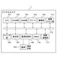
図2は、デジタルカメラ1の構成を示すブロック図である。 FIG. 2 is a block diagram showing the configuration of the digital camera 1.
図2において、デジタルカメラ1は、CPU101、ROM部102、RAM部103、タイマ104、撮像部105、スイッチ部106、表示部107、電源制御部108、電源109、DMAC(Direct Memory Access Controller)110、無線通信部111、内部バス112、画像メモリ部113を備えている。 2, the digital camera 1 includes a
CPU101は、撮像部105、無線通信部111等のデジタルカメラ各部を制御する中央制御装置であり、必要に応じて、データ変換等のデータ処理を行う機能も有する。また、CPU101は、プログラム命令コードに基づき図8及び図9のフローチャートに示す処理を実行する。ROM部102は、CPU101が読み出すプログラム命令コード等を格納しているメモリである。RAM部103は、CPU101が必要に応じてデータの書き込みや読み出しを行うためのメモリである。タイマ104は、CPU101の制御に基づき計時を開始し、設定された時間の経過をCPU101に通知する。 The
撮像部105は、被写体の光学像を画像信号に変換する等の撮像動作を行う。画像メモリ部113は、撮像した画像データを記憶するものであり、デジタルカメラ内蔵のフラッシュROM、或いはデジタルカメラに着脱可能なメモリカード、或いは磁気記録媒体等として構成される。スイッチ部106は、電源スイッチ及び各種スイッチ(図7)から構成される。スイッチ部106が押下された場合は押下を示す情報がCPU101に通知される。もしくは、CPU101が定期的にスイッチ部106の状態を監視するように構成してもよい。表示部107は、CPU101の制御に基づき表示を行うLED、LCD(Liquid Crystal Display)、液晶パネル、デジタルカメラの各種操作機能を含む液晶タッチパネルディスプレイ等から構成される。 The
電源制御部108は、CPU101の制御に基づき動作し、後述の図8及び図9のフローチャートに示す手順に基づき電源部109の出力を制御する。電源部109は、例えば電池やAC100V入力を所望のDC電圧に変換するACアダプタ等から構成され、デジタルカメラ各部に電源を供給する。DMAC110は、無線通信部111の後述のMAC層制御部201内のメモリ(不図示)に対し、RAM部103や画像メモリ部113から撮像データ等を転送する際等に使用され、データ処理部、通信処理部の機能をそれぞれ担うものである。内部バス112は、CPU101と各部を接続する伝送路である。 The power
図3は、デジタルカメラ1の無線通信部111の構成を示すブロック図である。 FIG. 3 is a block diagram illustrating a configuration of the
図3において、無線通信部111は、MAC層制御部201、ベースバンド処理部202、IF(Intermediate Frequency)のI/Q(In phase/Quadrature)モデム部203、RF/IF変換部204、RF送受信部205を備えている。なお、プリンタ3の無線通信部の構成も図3と基本的に同様であり、図示及び説明は省略する。 In FIG. 3, a
MAC層制御部201は、IEEE std802.11bに従って動作するものであり、無線で送受信するフレームの組み立て/分解、制御フレームの生成、無線通信チャネルの獲得制御、通信速度の制御等を司る。MAC層制御部201は、内部バス112と接続されている。ベースバンド処理部202は、フレームの変復調、符号化/復号化、アナログ/デジタル変換等を行う。IFのI/Qモデム部203は、送信用IF信号及び受信用IF信号のフィルタリング、4相位相変調/復調等を行う。 The MAC
RF/IF変換部204は、IFのI/Qモデム部203から出力されるIF信号を入力してRF(Radio Frequency)信号に変換し、更にRF信号をRF送受信部205に出力し、RF信号をRF送受信部205を介してアンテナ206から出力させる。RF/IF変換部204は、逆にアンテナ206により受信したRF信号がRF送受信部205を介して入力された場合に、RF信号をIF信号に変換し、IF信号をI/Qモデム部203に出力する。RF送受信部205は、RF信号の増幅、MAC層制御部201の指示に基づき送信/受信の切り替え等を行う。 The RF /
アンテナ206は、RF送受信部205の出力信号を電磁波として出力したり、受信した電磁波をRF信号である電気信号に変換したりするためのものである。ベースバンド処理部202乃至アンテナ206まではIEEE std802.11b準拠の物理層を形成するためのものである。MAC層制御部201乃至アンテナ206が通信処理部として動作することで、デジタルカメラ外部と各種コマンドを含むデータの送受信が行われる。 The
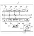
図4は、プリンタ3の構成を示すブロック図である。 FIG. 4 is a block diagram illustrating the configuration of the
図4において、プリンタ3は、CPU301、ROM部302、RAM部303、タイマ304、プリントエンジン部305、スイッチ部306、表示部307、電源制御部308、電源309、DMAC310、無線通信部311、内部バス312、ケーブル部313を備えている。 In FIG. 4, the
CPU301は、プリントエンジン部305、無線通信部311等のプリンタ各部を制御する中央制御装置であり、必要に応じて、データ変換等のデータ処理を行う機能も有する。また、CPU301は、プログラム命令コードに基づき図10及び図11のフローチャートに示す処理を実行する。ROM部302は、CPU301が読み出すプログラム命令コード等を格納しているメモリである。RAM部303は、CPU301が必要に応じてデータの書き込みや読み出しを行うためのメモリである。タイマ304は、CPU301の制御に基づき計時を開始し、設定された時間の経過をCPU301に通知する。 The
プリントエンジン部305は、例えば昇華型熱転写方式により印刷動作を行う。スイッチ部306は、電源スイッチ等を含む。スイッチ部306が押下された場合は押下を示す情報がCPU301に通知される。もしくは、CPU301が定期的にスイッチ部306の状態を監視するように構成してもよい。表示部307は、CPU301の制御に基づき各種表示を行う。 The
電源制御部308は、CPU301の制御に基づき動作し、電源部309の出力を制御する。電源部309は、例えば電池やAC100V入力を所望のDC電圧に変換するACアダプタ等から構成され、プリンタ各部に電源を供給する。DMAC310は、デジタルカメラ1の無線通信部111のMAC層制御部201内のメモリ(不図示)から受信したフレームを分解して格納された印刷データ等をRAM部303へ転送する際等に使用され、データ処理部、通信処理部の機能をそれぞれ担うものである。内部バス312は、CPU101と各部を接続する伝送路である。 The power
ケーブル部313は、通常時(非無線通信時)はケーブル2をケーブル部313の内部に巻き取った状態で収納し、無線通信時にはプリンタ3の筐体外部にケーブル2を引き出すことができるように構成されている。ケーブル部313は、ケーブル2の引き出しを検出する検出スイッチ314、ラチェット機構(不図示)を備えている。使用者によりケーブル部313からケーブル2が引き出されると、CPU301は、検出スイッチ314から出力されるオン信号(ケーブル引き出し信号)に基づき無線通信を可能に設定する。 The
ケーブル2は、ケーブル部313から引き出された位置でラチェット機構により固定することが可能となっている。プリンタ3においてデジタルカメラ1との無線通信を止める場合は、ケーブル2をケーブル部313から更に少しだけ引き出してラチェット機構を解除し、ケーブル2をケーブル部313内に巻き取ることで収納する。ケーブル部313内にケーブル2が収納されると、CPU301は、検出スイッチ314から出力されるオフ信号(ケーブル収納信号)に基づき無線通信を解除するように設定する。 The
即ち、ケーブル2は、プリンタ3とデジタルカメラ1との間を無線通信可能状態とする設定と、プリンタ3とデジタルカメラ1との間を無線通信不可状態(無線通信可能状態を解除した状態)とする設定とを切り替える、無線通信のスイッチ機能を有するものである。 That is, the
図5は、デジタルカメラ1及びプリンタ3から構成される無線通信システムとしてのプリントシステムを示す概略図である。 FIG. 5 is a schematic diagram illustrating a print system as a wireless communication system including the digital camera 1 and the
図5において、プリントシステムは、デジタルカメラ1及びプリンタ3を所定の無線データ伝送方式の無線通信を介して相互に接続することで(図示の矢印)、デジタルカメラ1からプリンタ3に対して画像データを送信しプリント出力させることが可能に構成されている。 In FIG. 5, the print system connects the digital camera 1 and the
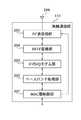
図6は、デジタルカメラ1及びプリンタ3に適用されるデータ処理の階層構造例を示す図である。 FIG. 6 is a diagram illustrating an example of a hierarchical structure of data processing applied to the digital camera 1 and the
図6において、データ処理の階層構造例としてBluetoothの階層構造を説明する。アプリケーション・レイヤ501は、装置や機能によって異なる。API(Application Interface)502は、アプリケーション・レイヤ501とRFCOMM504等との橋渡しをする部分である。なお、プロファイルの種類に応じて、APIに実装されるプロトコルスタックが異なる。 In FIG. 6, a Bluetooth hierarchical structure will be described as an example of a hierarchical structure of data processing. The
例えばシリアルポート・プロファイルの場合は、シリアルポート・エミュレーションと呼ばれるプロトコルスタックがAPIに必要になる。ヘッドセット・プロファイルの場合は、ヘッドセット・コントロールと呼ばれるプロトコルスタックがAPIに必要になる。ダイヤルアップ接続プロファイルやファクシミリ・プロファイルの場合は、ダイヤリング・アンド・コントロールと呼ばれるプロトコルスタックがAPIに必要になる。 For example, in the case of a serial port profile, a protocol stack called serial port emulation is required for the API. In the case of a headset profile, a protocol stack called headset control is required for the API. In the case of a dial-up connection profile or a facsimile profile, a protocol stack called dialing and control is required for the API.
SDP(Service Discovery Protocol)503は、アプリケーション・レイヤ501が通信相手先の装置のサービス情報を知るために使用するプロトコルである。RFCOMM504は、2つの機器のアプリケーション・レイヤを論理的に接続するために用いられるレイヤである。 An SDP (Service Discovery Protocol) 503 is a protocol used by the
LMP(Link Management Protocol)505は、ベースバンド層507で定義される通信リンクの制御や管理を行うためのプロトコルである。L2CAP(Logical Link Control & Adaptation Protocol)506は、論理チャネルの設定、パケットのセグメント化及び再構成、プロトコルの種類に応じてデータを振り分けたり多重したりする等の役割を果たすためのプロトコルである。 An LMP (Link Management Protocol) 505 is a protocol for controlling and managing a communication link defined in the
ベースバンド層507は、音声を一定周期のクロックに同期させて通信させるSCO(Synchronous Connection Oriented)という通信方式、または非音声データを非同期に通信させるACL(Asynchronous Connectionless)という通信方式の通信リンクの提供、SCOパケットやACLパケットの組み立て・分解や誤り訂正等を行う部分である。RF部508は、2.4GHz帯の周波数を用いて周波数ホッピング型のスペクトラム拡散方式により電波の送受信を行う部分である。 The
図7は、デジタルカメラ1の背面側の構成を示す図である。 FIG. 7 is a diagram showing the configuration of the back side of the digital camera 1.
図7において、デジタルカメラ1は、筐体背面側に、液晶表示素子(以下LCDと表記)107aと、LCD107aの近傍に配設され、上記スイッチ部106を構成する各種スイッチ106a、106b、106c、106dとを備えている。LCD107aは、バックライト駆動回路を有する。再生モードスイッチ106aは、表示部107を構成するLCD107aの表示を指示する際に操作する。スイッチ106b、106cは、表示すべき撮影画像を選択する際に操作する。プリントスイッチ106dは、撮影画像を外部のプリンタに印刷させるプリント指示を行う際に操作する。 In FIG. 7, the digital camera 1 is disposed on the back side of the housing on a liquid crystal display element (hereinafter referred to as LCD) 107 a and in the vicinity of the
次に、上記図1乃至図4に示したデジタルカメラ1及びプリンタ3の各構成を詳細に説明する。 Next, each configuration of the digital camera 1 and the
先ず、デジタルカメラ1側において、撮像部105は、所定位置に撮影レンズ(不図示)を介して入射する被写体光を受光し光電変換することで画像信号を生成するCCDと、CCDドライバと、アナログ/デジタル(以下A/Dと表記)変換回路を備えている。CCDは、CPU101の制御の下でCCDドライバにより駆動制御される。CCDの出力は、後段のA/D変換回路及びRAM部103を介してCPU101の入力に接続されている。また、表示部107には、表示用の画像メモリであるVRAMが配設されている。CPU101の出力は、VRAMを介してLCD107aの入力に接続される。 First, on the digital camera 1 side, the
無線通信部111は、プリンタ3側の無線通信部311と所定の無線データ伝送方式の無線通信を介して相互に接続され、デジタルカメラ及びプリンタ双方の無線通信を実現する。電源制御部108は、電源109の電圧をCPU101の制御の下で所定のタイミングをもって、表示部107、撮像部105、無線通信部111に供給する。なお、電源制御部108は、CPU101の制御の下で、設定時間の経過後に自動的に電源をオフ状態(パワーオフ状態)に切り換えるオートパワーオフ機能を有している。 The
一方、プリンタ3側において、無線通信部311は、デジタルカメラ1側の無線通信部111と所定の無線データ伝送方式の無線通信を介して相互に接続され、プリンタ及びデジタルカメラ双方の無線通信を実現する。無線通信部311の出力は、CPU301の入力に接続されている。CPU301の出力は、プリントエンジン部305、RAM部303等に接続されている。プリントエンジン部305は、用紙を搬送する紙搬送部、インクリボンを搬送するインクリボン搬送部、バッファメモリ、プリントヘッド、プリントヘッドを制御するヘッドコントローラ等を備えている。 On the other hand, on the
上記構成において、先ず、デジタルカメラ1側の動作を説明する。撮像部105のCCDにより被写体像が撮像された後、CCDから出力される画像信号(アナログ信号)がA/D変換回路に入力され、デジタル信号に変換された後、RAM部103に一時的に記憶される。RAM部103に記憶されたデータは、CPU101により読み出され、CPU内部の演算部によりホワイトバランス等の色変換やJPEG(Joint Photographic Experts Group)画像圧縮といった各種処理が施される。各種処理が施された画像データは、画像メモリ部113に撮影コマ毎に順次記憶される。 First, the operation on the digital camera 1 side will be described. After the subject image is picked up by the CCD of the
この状態で、使用者によりスイッチ部106の再生モードスイッチ106aが操作されると、操作情報がCPU101で認識され、且つCPU101の制御により画像メモリ部113の圧縮画像データが読み出される。更に、圧縮画像データがLCD107aへの表示のために伸長された後、表示部107に出力され、表示用の画像メモリであるVRAMに画像データが書き込まれることで、LCD107aに表示画像として表示される。このとき、LCD107aのバックライト駆動回路に電源が供給される。 In this state, when the user operates the
続いて、スイッチ部106のスイッチ106b、106cが使用者によって操作されると、画像メモリ部113に記憶された画像データが適宜選択され、上記同様に表示部107のLCD107aに表示画像として順次表示される。 Subsequently, when the user operates the
次に、プリンタ3側の動作を説明する。CPU301は、ダイレクトプリントを実行するために、デジタルカメラ1から無線通信部311を介して画像ファイルデータを受信し、画像ファイルデータを一旦RAM部303に蓄積する。更に、CPU301は、RAM部303に蓄積された画像ファイルデータの伸長処理を行いつつ、RAM部303の別の領域に先ず黄色(Y)、マゼンタ(M)、シアン(C)の色毎のデータを順次、1画面分展開した後、プリントエンジン部305によりダイレクトプリント処理を行う。この時、CPU301は、色毎のガンマ変換処理や輪郭強調処理等の処理も行う。 Next, the operation on the
また、CPU301は、プリントエンジン部305において紙搬送部を駆動して印刷する用紙を給紙し、印刷開始先頭位置に用紙を設定する。同時に、CPU301は、RAM部303に蓄積された印刷用画像データをバッファメモリに転送し、ヘッドコントローラによりプリントヘッドを制御して印刷を開始する。ここで、プリントヘッドは、用紙の1ライン分のデータを同時に印刷できるものであり、紙搬送部は、1ラインの印刷が終わる毎に用紙を1ライン分搬送する。 In addition, the
このように、CPU301は、プリントエンジン部305において、紙搬送部による用紙の給紙と、バッファメモリへの印刷用画像データの転送とを同期させながら行い、所望の画像の印刷動作が終了すると、紙搬送部を駆動して用紙を排紙する。 As described above, the
なお、デジタルカメラ1からプリンタ3へデータが送出されている間の少なくとも一部の期間は、節電のために、表示部107のLCD107aのバックライト駆動回路や、撮像時に動作する信号処理回路(例えばCCDドライバや撮影レンズの駆動系或いはストロボ充電回路等)の駆動を停止する。 In order to save power, the backlight drive circuit of the
ここで、上記図1に示すようにプリンタ3のケーブル2が引き出されている状態の場合は、デジタルカメラ1とプリンタ3とが所定の無線データ伝送形式により無線通信可能状態となる。他方、プリンタ3にケーブル2が収納されている状態の場合は、デジタルカメラ1とプリンタ3とは無線通信不可状態となる。 Here, in the state where the
デジタルカメラ及びプリンタ間の無線通信時には、デジタルカメラ1から接続確認信号をプリンタ3に対して送信することで、プリンタ3側でプリンタ3がデジタルカメラ1に接続されたことを認識し、応答信号をデジタルカメラ1側に返送する。使用者がデジタルカメラ1側で印刷を希望する画像を表示部107のLCD107aに再生画像として表示した状態で、プリントスイッチ106dを操作すると、プリンタ3で印刷動作が開始される。 At the time of wireless communication between the digital camera and the printer, a connection confirmation signal is transmitted from the digital camera 1 to the
次に、デジタルカメラ1のプリントスイッチ106dが操作されてからのデジタルカメラ1のCPU101とプリンタ3のCPU301の動作を図8乃至図11のフローチャートを参照しながら説明する。 Next, operations of the
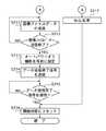
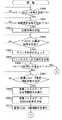
図8及び図9は、デジタルカメラ側のダイレクトプリント指示処理を示すフローチャートであり、図10及び図11は、プリンタ側のダイレクトプリント処理を示すフローチャートである。 8 and 9 are flowcharts showing the direct print instruction process on the digital camera side, and FIGS. 10 and 11 are flowcharts showing the direct print process on the printer side.
先ず、デジタルカメラ側のダイレクトプリント指示処理を説明する。 First, direct print instruction processing on the digital camera side will be described.
図8及び図9において、使用者によりプリントスイッチ106dが押下されると(ステップS701)、CPU101は、無線通信部111を介して接続確認信号をプリンタ3に送信し(ステップS702)、プリンタ3からの応答信号を受信したか否かを確認する(ステップS703)。即ち、CPU101は、プリンタ3が無線通信を介してデジタルカメラ1に接続されているか否かの確認を行う。プリンタ3から応答信号が得られない場合は、接続が確認できないので、ステップS717のエラー処理(以下N.G.処理と表記)に移行する。プリンタ3から応答信号が得られた場合は、接続が確認できたので、次のステップS704に進む。 8 and 9, when the user presses the
CPU101は、プリンタ3からの応答信号受信に伴い、無線通信部111を介してプリンタステータス要求信号をプリンタ3に送信し(ステップS704)、プリンタ3からプリンタステータス信号を受信したか否かを確認する(ステップS705)。CPU101は、無線通信部111を介してプリンタ3からプリンタステータス信号を受信すると、プリンタステータス信号を解析し(ステップS706)、プリンタ3がプリント可能な状態にあるか否かを判断する(ステップS707)。プリンタ3がプリント可能な状態にある場合は、次のステップS708に進む。プリンタ3がプリント不可能な状態にある場合は、ステップS717のN.G.処理に移行する。 Upon receiving the response signal from the
プリント不可能な状態とは、例えば、プリントエンジン部305でプリントが実行中である場合や、用紙収納部に用紙がセットされていない場合や、インクリボンがセットされていない場合である。また、プリントエンジン部305でジャムなどの不具合が生じている或いは故障している状態や、画像処理機能が故障している状態や、RAM部303が故障している或いは十分な記憶領域が確保できない状態などである。 The unprintable state is, for example, a case where printing is being executed by the
上記ステップS703或いはステップS707においてN.G.処理に移行した場合は、CPU101は、それぞれの状況に応じた状態(例えば接続エラーやプリンタエラーなどのメッセージ)を表示部107に表示し、使用者に報知する。更に、CPU101は、ケーブル2に内蔵されているLED4a、4b、4cを例えば一斉に点滅させることで、プリンタ3から離れた場所からもエラーがあったことを確認できるようにする(ステップS717)。 In step S703 or step S707, N.I. G. When the process is shifted to the process, the
CPU101は、プリンタ3がプリント可能状態であることに伴い、無線通信部111を介してデータ送信開始信号をプリンタ3に送信し(ステップS708)、プリンタ3からのデータ受信OK信号を待つ(ステップS709)。CPU101は、無線通信部111を介してプリンタ3からデータ受信OK信号を受信すると、電源制御部108のオートパワーオフ機能を無効となるように設定し(ステップS710)、無線通信部111を介してプリンタ3に画像ファイルデータの送信を開始する(ステップ711)。 As the
CPU101は、必要なデータ量の画像ファイルデータの送信を終了すると(ステップS712でYES)、電源制御部108のオートパワーオフ機能無効の設定を解除し、オートパワーオフ機能を有効に設定する(ステップS713)。更に、CPU101は、無線通信部111を介してデータ送信終了信号をプリンタ3に送信し(ステップS714)、プリンタ3からデータ受信完了信号を待つ(ステップS715)。CPU101は、無線通信部111を介してプリンタ3からデータ受信完了信号を受信すると、デジタルカメラ1の状態をプリントスイッチ106dが押下される以前の開始状態にリセットする(ステップS716)。 When the
次に、プリンタ側のダイレクトプリント処理を説明する。 Next, direct print processing on the printer side will be described.
図10及び図11において、CPU301は、プリンタ3のパワーオンの状態で、ケーブル部313の検出スイッチ314の状態をモニタしている。使用者がプリンタ及びデジタルカメラ間で無線通信を行うべくケーブル部313からケーブル2を引き出した場合には、検出スイッチ314がオンとなりケーブル引き出し信号(オン信号)を出力する。これに伴い、CPU301は、検出スイッチ314からケーブル引き出し信号を受信し(ステップS800)、無線通信部311を介してデジタルカメラ1と無線通信可能な状態となる。 10 and 11, the
CPU301は、無線通信可能な状態になると、無線通信部311への入力信号をモニタし、入力信号に応じて無線通信部311へ応答信号を出力し、プリンタ3の動作を制御する。CPU301は、無線通信部311を介してデジタルカメラ1から接続確認信号を受信すると(ステップS801でYES)、プリンタ3が無線通信によりデジタルカメラ1に接続していることをデジタルカメラ1に伝える応答信号を、無線通信部311を介してデジタルカメラ1に送信する(ステップS802)。 When the wireless communication is enabled, the
次に、CPU301は、無線通信部311を介してデジタルカメラ1からプリンタステータス要求信号を受信すると(ステップS803でYES)、プリンタ3内部のチェックを行う(ステップS804)。CPU301は、無線通信部311を介してチェックの結果をプリンタステータス信号としてデジタルカメラ1に送信する(ステップS805)。プリンタ3内部に異常がある場合は(ステップS806でYES)、ステップS822のN.G.処理に移行する。 Next, when receiving a printer status request signal from the digital camera 1 via the wireless communication unit 311 (YES in step S803), the
異常な状態とは、例えば、プリンタ3の用紙収納部に用紙がセットされていない場合や、インクリボンがセットされていない場合である。また、プリントエンジン部305でジャムなどの不具合が生じている或いは故障している状態や、画像処理機能が故障している状態や、RAM部303が故障している或いは十分な記憶領域が確保できない状態などである。 The abnormal state is, for example, a case where no paper is set in the paper storage unit of the
上記ステップS806においてN.G.処理に移行した場合は、CPU101は、状況に応じた状態を表示部107に表示し、使用者に報知する。更に、CPU101は、ケーブル2に内蔵されているLED4a、4b、4cを例えば一斉に点滅させることで、プリンタ3から離れた場所からもエラーがあったことを確認できるようにする(ステップS822)。 In step S806, N. G. When the process is shifted to the process, the
CPU301は、無線通信部311を介してデジタルカメラ1からデータ送信開始信号を受信すると(ステップS807でYES)、デジタルカメラ1からの画像ファイルデータの受信準備動作を実行する(ステップS808)。次に、CPU301は、無線通信部311を介して画像ファイルデータ受信OK信号をデジタルカメラ1に送信する(ステップS809)。次に、CPU301は、無線通信部311を介してデジタルカメラ1から画像ファイルデータを受信する動作を実行する(ステップS810)。 When the
CPU301は、無線通信部311を介してデジタルカメラ1から画像ファイルデータ送信終了信号を受信すると(ステップS811でYES)、画像ファイルデータ受信動作を終了し(ステップS812)、無線通信部311を介して画像ファイルデータ受信完了信号をデジタルカメラ1に送信する(ステップS813)。 When the
この場合、デジタルカメラ1からプリンタ3に送信する画像ファイルデータには、デジタルカメラ1での撮影条件(例えばシャッタスピードや露出時間等)を示すデータを含ませてもよい。なお、本実施の形態では、画像ファイルデータとしてJPEG方式で圧縮された画像ファイルデータを例に挙げるものとするが、これに限定されるものではない。 In this case, the image file data transmitted from the digital camera 1 to the
次に、CPU301は、JPEG方式で圧縮された画像ファイルデータに対し圧縮時と逆に伸長する画像処理を施し、元の画像ファイルデータに伸長展開する(ステップS814)。次に、CPU301は、画像ファイルデータに含まれている撮影条件を示すデータに基づき、適応する画像データ補正テーブルをROM部302から読み出して設定する(ステップS815)。この画像データ補正テーブルは、プリンタ3に設定された色変換テーブルと組み合わされて、印刷用の色毎に画像データを変換して印刷データとするためのものである。 Next, the
次に、CPU301は、印刷用インクリボンの色に適合させて、まず、1色目を印刷するために、イエロー(以下“Y”と表記)の色データをRAM部303に展開する(ステップS816)。CPU301は、展開された色データを順次1ライン毎にプリントエンジン部305のヘッドコントローラに出力し、プリントヘッドを介して1画面分のYの印刷を行う(ステップS817)。 Next, the
次いで、CPU301は、印刷用の他の色、マゼンタ(以下“M”と表記)について、ステップS818及びステップS819で同様に1画面分印刷を行い、シアン(以下“C”と表記)について、ステップS820及びステップS821で同様に1画面分印刷を行う。これにより、1画面全てのフルカラー印刷が終了する。 Next, the
上述したように、デジタルカメラ1がプリンタ3との間でデータ通信を実行中の場合は、デジタルカメラ1のオートパワーオフ機能を無効となるように設定し、データ通信が終了した場合は、デジタルカメラ1のオートパワーオフ機能を有効となるように設定する。これにより、デジタルカメラ及びプリンタ間のデータ通信実行中に、デジタルカメラ1のオートパワーオフ機能が働いて電源オフになることを防止することができる。また、データ通信が終了すれば、元のオートパワーオフ機能を働かせることができる。 As described above, when the digital camera 1 is executing data communication with the
次に、プリンタ3に装備されたケーブル2に関わる動作について説明する。 Next, operations related to the
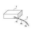
図12は、プリンタ3からケーブル2を引き出している状態を示す図であり、図13は、プリンタ3からケーブル2を引き出した状態を示す図である。また、図14は、デジタルカメラ1からプリンタ3へ無線データ通信が行われている状態を示す図であり、図15は、プリンタ3からデジタルカメラ1へ無線データ通信が行われている状態を示す図である。 FIG. 12 is a diagram illustrating a state where the
図12乃至図15において、図12に示すように、使用者はプリンタ3のケーブル部313に巻き取られて収納されているケーブル2を引き出す。図13に示すように、プリンタ3からケーブル2が引き出されると、プリンタ3はデジタルカメラ1と無線通信可能な状態へ遷移する。 12 to 15, as shown in FIG. 12, the user pulls out the
図14に示すように、プリンタ3がデジタルカメラ1から無線通信の信号を受信すると、プリンタ3のCPU301は、ケーブル2に内蔵されている3つのLED4a、4b、4cを、例えば、それぞれ4a→4b→4cの順番に1秒間ずつ緑色に点灯させる。これにより、ケーブル2は、あたかもデジタルカメラ1から送信される無線信号がプリンタ3内部に吸い込まれるように見えるため、プリンタ3が無線信号を受信していることが感覚的に分かるようになっている。 As illustrated in FIG. 14, when the
他方、図15に示すように、プリンタ3からデジタルカメラ1に無線通信で信号を送信する場合には、プリンタ3のCPU301は、ケーブル2に内蔵されている3つのLED4a、4b、4cを、例えば、それぞれ4c→4b→4aの順番に1秒間ずつ点灯させる。これにより、ケーブル2は、あたかもプリンタ3から送信される無線信号がプリンタ3からデジタルカメラ1へ出て行くように見えるため、プリンタ3が無線信号を送信していることが感覚的に分かるようになっている。 On the other hand, as shown in FIG. 15, when a signal is transmitted from the
また、デジタルカメラ1やプリンタ3に下記のような各種の不具合(所定の状況)が発生した場合は、プリンタ3のCPU301は、ケーブル2のLED4a、4b、4cを例えば同時に赤色を点滅させることで、離れた場所にいる使用者へ報知するようになっている。各種の不具合とは、デジタルカメラ1とプリンタ3が何らかの理由で無線通信ができなくなった場合、プリンタ3の印刷時に不具合が発生した場合、プリンタ3でインク切れや用紙切れが発生した場合、デジタルカメラ1から何らかの不具合が発生したことをプリンタ3に通信してきた場合などである。 When the following various problems (predetermined situations) occur in the digital camera 1 or the
以上説明したように、本実施の形態によれば、プリンタ3がデジタルカメラ1との無線通信時には、ケーブル2のLED4a、4b、4cを点灯させるため、無線通信が行われていることをプリンタ3から離れた場所からでも視認可能であり、使用者にとって安心感が生ずるという効果がある。 As described above, according to the present embodiment, when the
また、ケーブル2がプリンタ3から引き出された場合は無線通信可能状態に設定し、ケーブル2がプリンタ3に収納された場合は無線通信不可状態に設定するため、難しい設定が一切無く、有線通信の感覚を持って無線通信の接続を行うことができ、利便性に優れるという効果がある。 Also, when the
また、プリンタ3がデジタルカメラ1からのデータ受信時は、ケーブル先端側のLEDからケーブル基端側(プリンタ側)のLEDに向けて順番に点灯させ、プリンタ3からデジタルカメラ1へのデータ送信時は、ケーブル基端側のLEDからケーブル先端側のLEDに向けて順番に点灯させるため、無線通信が行われていることをプリンタ3から離れた場所からでも視認可能であり、使用者にとって安心感が大きくなるという効果がある。 When the
また、プリンタ及びデジタルカメラ間の無線通信に関わる不具合や、プリンタ及びデジタルカメラそれぞれに関わる不具合等が発生した場合は、各LEDを一斉に発光させるため、プリンタ3から離れた場所からでも不具合の発生を簡単に視認できるという効果がある。 In addition, if a problem related to wireless communication between the printer and the digital camera, or a problem related to each of the printer and the digital camera occurs, the LEDs are emitted all at once. Is easily visible.
また、デジタルカメラ1がプリンタ3と無線通信中の場合はオートパワーオフ機能を無効に設定し、デジタルカメラ1がプリンタ3と無線通信が終了した場合はオートパワーオフ機能を有効に設定するため、無線通信中にオートパワーオフ機能が作動してデジタルカメラ1の電源が切断されることを防止することができる。 Further, when the digital camera 1 is wirelessly communicating with the
[第2の実施の形態]
本発明の第2の実施の形態は、上述した第1の実施の形態に対して、デジタルカメラがデータ保存装置との間で無線通信を行う点において相違する。本実施の形態のその他の要素は、上述した第1の実施の形態(図2、図3、図6、図7)の対応するものと同一なので、説明を省略する。[Second Embodiment]
The second embodiment of the present invention is different from the above-described first embodiment in that the digital camera performs wireless communication with the data storage device. The other elements of the present embodiment are the same as the corresponding ones of the first embodiment (FIGS. 2, 3, 6, and 7) described above, and thus description thereof is omitted.
図16は、本実施の形態に係るデータ処理装置としてのデータ保存装置の構成を示すブロック図である。 FIG. 16 is a block diagram showing a configuration of a data storage device as a data processing device according to the present embodiment.
図16において、データ保存装置5は、CPU301、ROM部302、RAM部303、タイマ304、データ保存エンジン部501、スイッチ部306、表示部307、電源制御部308、電源309、DMAC310、無線通信部311、内部バス312、ケーブル部313を備えている。 In FIG. 16, the
データ保存装置5は、上記第1の実施の形態のプリンタ3のプリントエンジン部305をデータ保存エンジン部501に置き換えたものである。データ保存エンジン部501は、具体的にはDVDレコーダやハードディスク等の大容量の記憶装置として搭載されるものであり、デジタルカメラ1から送信された画像ファイルデータを直接書き込むように構成されている。 The
上記第1の実施の形態では、デジタルカメラ1で画像ファイルデータをプリント信号に変換することで、デジタルカメラ及びプリンタ間でプリント信号を送受信した。これに対し、本実施の形態では、デジタルカメラ内部に保存している画像ファイルデータをそのままのファイル形式でデジタルカメラ及びデータ保存装置間で送受信する。更に、データ保存装置5のCPU301が、画像ファイルデータを複製してデータ保存エンジン部501に保存して行くように制御を行う。 In the first embodiment, the digital camera 1 converts image file data into a print signal, so that the print signal is transmitted and received between the digital camera and the printer. In contrast, in the present embodiment, image file data stored in the digital camera is transmitted and received between the digital camera and the data storage device in the same file format. Further, the
ケーブル部313は、通常時(非無線通信時)はケーブル503をケーブル部313の内部に倒した状態で収納し、無線通信時にはデータ保存装置5の筐体上面部に対し垂直にケーブル2を引き起こすことができるように構成されている。ケーブル部313は、ケーブル503が引き起こされたことを検出する検出スイッチ502を備えている。 The
ケーブル503をケーブル部313から引き起こす動作で、無線通信のスイッチ機能を働かせる。これにより、上記第1の実施の形態のようなケーブルをケーブル部から引き出すのと等価な動作が可能となる。具体的には、使用者によりケーブル部313からケーブル503が引き起こされると、CPU301は、検出スイッチ502から出力されるオン信号に基づき無線通信を可能に設定する。 The operation of causing the
即ち、ケーブル503は、データ保存装置5とデジタルカメラ1との間を無線通信可能状態とする設定と、データ保存装置5とデジタルカメラ1との間を無線通信不可状態(無線通信可能状態を解除した状態)とする設定とを切り替える、無線通信のスイッチ機能を有するものである。 That is, the
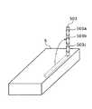
図17は、データ保存装置5のケーブル503を引き起こした状態を示す斜視図である。 FIG. 17 is a perspective view showing a state in which the
図17において、ケーブル503は、硬質材料からなる中空のアンテナ形状を有し、中空のケーブル材料内部に発光体としてLED503a、503b、503cを備えている。LED503a、503b、503cは、ケーブル503の長手方向の先端側から基端側(データ保存装置側)に所定間隔をおいて配設されている。LED503a、503b、503cは、それぞれ、例えば緑と赤の2色LEDとして構成されており、データ保存装置5のCPU301により個別に点灯(点滅)/消灯が制御される。 In FIG. 17, a
データ保存装置5がデジタルカメラ1からデータを受信する場合は、CPU301は、ケーブル503のLED503a、503b、503cを、例えば、それぞれ503a→503b→503cの順番に1秒間ずつ緑色に点灯させる。これにより、ケーブル503は、あたかもデジタルカメラ1から送信されるデータがデータ保存装置5内部に吸い込まれるように見えるため、データ保存装置5がデータを受信していることが感覚的に明確となる。 When the
他方、データ保存装置5がデジタルカメラ1にデータを送信する場合は、CPU301は、ケーブル503のLED503a、503b、503cを、例えば、それぞれ503c→503b→503aの順番に点灯させる。これにより、ケーブル503は、あたかもデータ保存装置5からデジタルカメラ1に送信されるデータがデータ保存装置5から出て行くように見えるため、データ保存装置5がデータを送信していることが感覚的に明確となる。 On the other hand, when the
上述したケーブル503のLED点灯制御により、遠くからでもデータ保存装置501がデータ送信またはデータ受信をしている様子を容易に視認することが可能であり、無線通信においても不安感無くデータ保存装置5を取り扱うことができる。 By controlling the LED lighting of the
また、上記第1の実施の形態と同様に、デジタルカメラ1やデータ保存装置5に下記のような各種の不具合が発生した場合は、データ保存装置5のCPU301が、ケーブル503のLED503a、503b、503cを例えば同時に赤色を点滅させることで、離れた場所にいる使用者へ報知するようにしてもよい。各種の不具合とは、デジタルカメラ1とデータ保存装置5が何らかの理由で無線通信ができなくなった場合、データ保存装置5に不具合が発生した場合、デジタルカメラ1から何らかの不具合が発生したことをデータ保存装置5に通信してきた場合などである。 Similarly to the first embodiment, when the following various problems occur in the digital camera 1 or the
以上説明したように、本実施の形態によれば、データ保存装置5がデジタルカメラ1との無線通信時には、ケーブル503のLED503a、503b、503cを点灯させるため、無線通信が行われていることをデータ保存装置5から離れた場所からでも視認可能であり、使用者にとって安心感が生ずるという効果がある。 As described above, according to the present embodiment, when the
また、ケーブル503がデータ保存装置5から引き出された場合は無線通信可能状態に設定し、ケーブル503がデータ保存装置5に収納された場合は無線通信不可状態に設定するため、難しい設定が一切無く、有線通信の感覚を持って無線通信の接続を行うことができ、利便性に優れるという効果がある。 In addition, when the
また、データ保存装置5がデジタルカメラ1からのデータ受信時は、ケーブル先端側のLEDからケーブル基端側(プリンタ側)のLEDに向けて順番に点灯させ、データ保存装置5からデジタルカメラ1へのデータ送信時は、ケーブル基端側のLEDからケーブル先端側のLEDに向けて順番に点灯させるため、無線通信が行われていることをデータ保存装置5から離れた場所からでも視認可能であり、使用者にとって安心感が大きくなるという効果がある。 When the
また、データ保存装置及びデジタルカメラ間の無線通信に関わる不具合や、データ保存装置及びデジタルカメラそれぞれに関わる不具合等が発生した場合は、各LEDを一斉に発光させるため、データ保存装置5から離れた場所からでも不具合の発生を簡単に視認できるという効果がある。 In addition, when troubles related to wireless communication between the data storage device and the digital camera, or troubles related to the data storage device and the digital camera occur, the LEDs are separated from the
[他の実施の形態]
上記第1の実施の形態では、ケーブル2に3つのLED4a、4b、4cを配設し、それぞれ緑と赤の2色LEDで構成した場合を例に挙げたが、本発明は、これに限定されるものではない。ケーブル2に配設するLEDの個数及び色の組み合わせは任意とすることが可能である。[Other embodiments]
In the first embodiment, the case where the three
上記第1の実施の形態では、プリンタ3における無線信号受信時に、LEDを4a→4b→4cの順番に1秒間ずつ緑色に点灯させ、無線信号送信時に、LEDを4c→4b→4aの順番に1秒間ずつ点灯させたが、本発明は、これに限定されるものではない。LEDの点灯時間や点灯色は任意とすることが可能である。 In the first embodiment, when the wireless signal is received by the
上記第2の実施の形態では、ケーブル503に3つのLED503a、503b、503cを配設し、それぞれ緑と赤の2色LEDで構成した場合を例に挙げたが、本発明は、これに限定されるものではない。ケーブル503に配設するLEDの個数及び色の組み合わせは任意とすることが可能である。 In the second embodiment, the case where the three
上記第2の実施の形態では、データ保存装置501におけるデータ受信時に、LEDを503a→503b→503cの順番に1秒間ずつ緑色に点灯させ、データ送信時に、LEDを503c→503b→503aの順番に点灯させたが、本発明は、これに限定されるものではない。LEDの点灯時間や点灯色は任意とすることが可能である。 In the second embodiment, when the
また、本発明の目的は、実施形態の機能を実現するソフトウェアのプログラムコードを記録した記憶媒体を、システム或いは装置に供給し、そのシステム或いは装置のコンピュータ(またはCPUやMPU等)が記憶媒体に格納されたプログラムコードを読み出して実行することによっても達成される。 In addition, an object of the present invention is to supply a storage medium storing software program codes for realizing the functions of the embodiments to a system or apparatus, and a computer (or CPU, MPU, etc.) of the system or apparatus as a storage medium. This can also be achieved by reading and executing the stored program code.
この場合、記憶媒体から読み出されたプログラムコード自体が前述した実施の形態の機能を実現することになり、そのプログラムコード及び該プログラムコードを記憶した記憶媒体は本発明を構成することになる。 In this case, the program code itself read from the storage medium realizes the functions of the above-described embodiments, and the program code and the storage medium storing the program code constitute the present invention.
また、プログラムコードを供給するための記憶媒体としては、例えば、フロッピー(登録商標)ディスク、ハードディスク、光磁気ディスク、CD−ROM、CD−R、CD−RW、DVD−ROM、DVD−RAM、DVD−RW、DVD+RW、磁気テープ、不揮発性のメモリカード、ROM等を用いることができる。または、プログラムコードをネットワークを介してダウンロードしてもよい。 Examples of the storage medium for supplying the program code include a floppy (registered trademark) disk, a hard disk, a magneto-optical disk, a CD-ROM, a CD-R, a CD-RW, a DVD-ROM, a DVD-RAM, and a DVD. -RW, DVD + RW, magnetic tape, nonvolatile memory card, ROM, etc. can be used. Alternatively, the program code may be downloaded via a network.
また、コンピュータが読み出したプログラムコードを実行することにより、上記実施の形態の機能が実現されるだけでなく、そのプログラムコードの指示に基づき、コンピュータ上で稼動しているOS(オペレーティングシステム)等が実際の処理の一部または全部を行い、その処理によって前述した実施形態の機能が実現される場合も含まれる。 Further, by executing the program code read by the computer, not only the functions of the above-described embodiments are realized, but also an OS (operating system) running on the computer based on the instruction of the program code. A case where part or all of the actual processing is performed and the functions of the above-described embodiments are realized by the processing is also included.
更に、記憶媒体から読み出されたプログラムコードが、コンピュータに挿入された機能拡張ボードやコンピュータに接続された機能拡張ユニットに備わるメモリに書き込まれた後、そのプログラムコードの指示に基づき、その機能拡張ボードや機能拡張ユニットに備わるCPU等が実際の処理の一部または全部を行い、その処理によって前述した実施形態の機能が実現される場合も含まれる。 Further, after the program code read from the storage medium is written in a memory provided in a function expansion board inserted into the computer or a function expansion unit connected to the computer, the function expansion is performed based on the instruction of the program code. This includes the case where the CPU or the like provided in the board or the function expansion unit performs part or all of the actual processing, and the functions of the above-described embodiments are realized by the processing.
また、コンピュータが読み出したプログラムコードを実行することにより、前述した各実施の形態の機能が実現されるだけでなく、そのプログラムコードの指示に基づき、コンピュータ上で稼働しているOSなどが実際の処理の一部または全部を行い、その処理によって前述した各実施の形態の機能が実現される場合も、本発明に含まれることは言うまでもない。 Further, by executing the program code read by the computer, not only the functions of the above-described embodiments are realized, but the OS running on the computer based on the instruction of the program code is actually used. Needless to say, the present invention also includes a case in which the functions of the above-described embodiments are realized by performing part or all of the processing and the processing.
この場合、上記プログラムは、該プログラムを記憶した記憶媒体から直接、又はインターネット、商用ネットワーク、若しくはローカルエリアネットワーク等に接続された不図示の他のコンピュータやデータベース等からダウンロードすることにより供給される。 In this case, the program is supplied by downloading directly from a storage medium storing the program or from another computer or database (not shown) connected to the Internet, a commercial network, a local area network, or the like.
上記実施の形態では、プリンタの印刷方式を昇華型熱転写方式とした場合を例に挙げたが、本発明は、昇華型熱転写方式に限定されるものではなく、電子写真方式、インクジェット方式、感熱方式、静電方式、放電破壊方式など各種印刷方式に適用することができる。 In the above embodiment, the case where the printing system of the printer is a sublimation type thermal transfer system is taken as an example, but the present invention is not limited to the sublimation type thermal transfer system, and is an electrophotographic system, an inkjet system, a thermal system. It can be applied to various printing methods such as electrostatic method and electric discharge destruction method.
上記プログラムの形態は、オブジェクトコード、インタプリタにより実行されるプログラムコード、OS(オペレーティングシステム)に供給されるスクリプトデータ等の形態から成ってもよい。 The form of the program may be in the form of object code, program code executed by an interpreter, script data supplied to an OS (operating system), and the like.
1 デジタルカメラ(撮像装置)
2 ケーブル(切替手段)
3 プリンタ(データ処理装置、印刷装置)
4a、4b、4c LED(発光手段)
5 データ保存装置(データ処理装置)
101 CPU(設定手段)
111 無線通信部(無線通信手段)
108 電源制御部(電源制御手段)
301 CPU(制御手段)
311 無線通信部(無線通信手段)
313 ケーブル部
314 検出スイッチ(検出手段)
501 データ保存エンジン部
502 検出スイッチ(検出手段)
503 ケーブル(切替手段)
503a、503b、503c LED(発光手段)1 Digital camera (imaging device)
2 Cable (switching means)
3 Printer (data processing device, printing device)
4a, 4b, 4c LED (light emitting means)
5 Data storage device (data processing device)
101 CPU (setting means)
111 Wireless communication unit (wireless communication means)
108 Power control unit (power control means)
301 CPU (control means)
311 Wireless communication unit (wireless communication means)
313
501 Data
503 cable (switching means)
503a, 503b, 503c LED (light emitting means)
Claims (12)
Translated fromJapanese発光手段が付設され、無線通信可能状態と無線通信不可状態を切り替える切替手段と、
前記切替手段により前記無線通信可能状態に切り替えられた場合で、前記無線通信手段により前記撮像装置との無線通信時には、前記切替手段の前記発光手段を発光させる制御手段と、
を備えることを特徴とするデータ処理装置。Wireless communication means for performing wireless communication with the imaging device;
A light emitting means, a switching means for switching between a wireless communication enabled state and a wireless communication disabled state;
Control means for causing the light emitting means of the switching means to emit light during wireless communication with the imaging device by the wireless communication means when the wireless communication means is switched to the wireless communication enabled state by the switching means.
A data processing apparatus comprising:
前記切替手段は、前記データ処理装置に対して収納及び引き出し可能に構成され、
前記制御手段は、前記切替手段が前記データ処理装置から引き出されたことを前記検出手段により検出した場合は、前記無線通信可能状態に設定し、前記切替手段が前記データ処理装置に収納されたことを前記検出手段により検出した場合は、前記無線通信不可状態に設定することを特徴とする請求項1記載のデータ処理装置。It further comprises detection means for detecting the state of the switching means,
The switching means is configured to be capable of being stored and withdrawn from the data processing device,
The control means sets the wireless communication enabled state when the detection means detects that the switching means is pulled out from the data processing device, and the switching means is accommodated in the data processing device. The data processing apparatus according to claim 1, wherein when the detection means detects the wireless communication, the wireless communication disabled state is set.
前記切替手段は、前記データ処理装置に対して収納及び引き起こし可能に構成され、
前記制御手段は、前記切替手段が前記データ処理装置から引き起こされたことを前記検出手段により検出した場合は、前記無線通信可能状態に設定し、前記切替手段が前記データ処理装置に収納されたことを前記検出手段により検出した場合は、前記無線通信不可状態に設定することを特徴とする請求項1記載のデータ処理装置。It further comprises detection means for detecting the state of the switching means,
The switching means is configured to be housed and triggered with respect to the data processing device,
The control means sets the wireless communication enabled state when the detection means detects that the switching means is caused by the data processing device, and the switching means is stored in the data processing device. The data processing apparatus according to claim 1, wherein when the detection means detects the wireless communication, the wireless communication disabled state is set.
前記制御手段は、前記撮像装置からのデータ受信時は、前記ケーブルの先端側の前記発光手段から前記ケーブルの基端側の前記発光手段に向けて順番に発光させ、前記撮像装置へのデータ送信時は、前記ケーブルの基端側の前記発光手段から前記ケーブルの先端側の前記発光手段に向けて順番に発光させることを特徴とする請求項1乃至3の何れかに記載のデータ処理装置。The switching means is configured as a cable in which a plurality of the light emitting means are arranged in the longitudinal direction,
When receiving data from the imaging device, the control means sequentially emits light from the light emitting means at the distal end side of the cable toward the light emitting means at the proximal end side of the cable, and transmits data to the imaging apparatus. 4. The data processing apparatus according to claim 1, wherein light is emitted in order from the light emitting means on the proximal end side of the cable toward the light emitting means on the distal end side of the cable. 5.
データ処理装置と無線通信を行う無線通信手段と、
前記無線通信手段により前記データ処理装置と無線通信中の場合は、前記オートパワーオフ機能を無効に設定し、前記データ処理装置と無線通信が終了した場合は、前記オートパワーオフ機能を有効に設定する設定手段と、
を備えることを特徴とする撮像装置。Power control means having an auto power off function for cutting off the power after a set time has elapsed;
Wireless communication means for performing wireless communication with the data processing device;
When wireless communication with the data processing device is being performed by the wireless communication means, the auto power off function is set to be invalid, and when wireless communication with the data processing device is completed, the auto power off function is set to be valid. Setting means to
An imaging apparatus comprising:
撮像装置と無線通信を行う無線通信ステップと、
前記切替手段により前記無線通信可能状態に切り替えられた場合で、前記無線通信ステップにより前記撮像装置との無線通信時には、前記切替手段の前記発光手段を発光させる制御ステップと、
を備えることを特徴とする制御方法。A control method of a data processing apparatus provided with a switching means for switching between a wireless communication enabled state and a wireless communication disabled state, provided with a light emitting means,
A wireless communication step for performing wireless communication with the imaging device;
A control step of causing the light emitting means of the switching means to emit light during wireless communication with the imaging device by the wireless communication step when the wireless communication step is switched to the wireless communication enabled state by the switching means;
A control method comprising:
データ処理装置と無線通信を行う無線通信ステップと、
前記無線通信ステップにより前記データ処理装置と無線通信中の場合は、前記オートパワーオフ機能を無効に設定し、前記データ処理装置と無線通信が終了した場合は、前記オートパワーオフ機能を有効に設定する設定ステップと、
を備えることを特徴とする制御方法。A method for controlling an image pickup apparatus having an auto power off function for cutting off a power supply after a set time has elapsed,
A wireless communication step for performing wireless communication with the data processing device;
The auto power off function is set to invalid when wireless communication is being performed with the data processing device by the wireless communication step, and the auto power off function is set to valid when wireless communication with the data processing device is terminated. A setting step to
A control method comprising:
撮像装置と無線通信を行う無線通信モジュールと、
前記切替手段により前記無線通信可能状態に切り替えられた場合で、前記無線通信モジュールにより前記撮像装置との無線通信時には、前記切替手段の前記発光手段を発光させる制御モジュールと、
を備えることを特徴とするプログラム。A program that causes a computer to execute a control method of a data processing apparatus that includes a switching unit that switches between a wireless communication enabled state and a wireless communication disabled state, to which a light emitting unit is attached,
A wireless communication module for performing wireless communication with the imaging device;
A control module for causing the light emitting means of the switching means to emit light when the wireless communication module is switched to the wireless communicable state by the switching means and wirelessly communicating with the imaging device by the wireless communication module;
A program comprising:
データ処理装置と無線通信を行う無線通信モジュールと、
前記無線通信モジュールにより前記データ処理装置と無線通信中の場合は、前記オートパワーオフ機能を無効に設定し、前記データ処理装置と無線通信が終了した場合は、前記オートパワーオフ機能を有効に設定する設定モジュールと、
を備えることを特徴とするプログラム。A program for causing a computer to execute a control method of an imaging apparatus having an auto power-off function for cutting off a power supply after a set time has elapsed,
A wireless communication module for performing wireless communication with the data processing device;
When wireless communication with the data processing device is being performed by the wireless communication module, the auto power off function is disabled, and when wireless communication with the data processing device is terminated, the auto power off function is enabled. A configuration module to
A program comprising:
Priority Applications (1)
| Application Number | Priority Date | Filing Date | Title |
|---|---|---|---|
| JP2005050967AJP2006236076A (en) | 2005-02-25 | 2005-02-25 | Data processing apparatus, imaging apparatus, wireless communication system, control method, and program |
Applications Claiming Priority (1)
| Application Number | Priority Date | Filing Date | Title |
|---|---|---|---|
| JP2005050967AJP2006236076A (en) | 2005-02-25 | 2005-02-25 | Data processing apparatus, imaging apparatus, wireless communication system, control method, and program |
Publications (1)
| Publication Number | Publication Date |
|---|---|
| JP2006236076Atrue JP2006236076A (en) | 2006-09-07 |
Family
ID=37043645
Family Applications (1)
| Application Number | Title | Priority Date | Filing Date |
|---|---|---|---|
| JP2005050967APendingJP2006236076A (en) | 2005-02-25 | 2005-02-25 | Data processing apparatus, imaging apparatus, wireless communication system, control method, and program |
Country Status (1)
| Country | Link |
|---|---|
| JP (1) | JP2006236076A (en) |
Cited By (6)
| Publication number | Priority date | Publication date | Assignee | Title |
|---|---|---|---|---|
| JP2009201031A (en)* | 2008-02-25 | 2009-09-03 | Canon Inc | Image processing device and control method thereof |
| JP2011183594A (en)* | 2010-03-05 | 2011-09-22 | Toshiba Tec Corp | Portable printer, and system |
| WO2015029823A1 (en)* | 2013-08-28 | 2015-03-05 | 株式会社 東芝 | Imaging system and imaging device |
| JP2015159989A (en)* | 2014-02-27 | 2015-09-07 | シャープ株式会社 | washing machine |
| JP2017130108A (en)* | 2016-01-21 | 2017-07-27 | キヤノン株式会社 | COMMUNICATION DEVICE, ITS CONTROL METHOD, AND PROGRAM |
| JP2018179318A (en)* | 2017-04-04 | 2018-11-15 | 三菱電機株式会社 | Cooker and cooker system |
- 2005
- 2005-02-25JPJP2005050967Apatent/JP2006236076A/enactivePending
Cited By (11)
| Publication number | Priority date | Publication date | Assignee | Title |
|---|---|---|---|---|
| JP2009201031A (en)* | 2008-02-25 | 2009-09-03 | Canon Inc | Image processing device and control method thereof |
| JP2011183594A (en)* | 2010-03-05 | 2011-09-22 | Toshiba Tec Corp | Portable printer, and system |
| WO2015029823A1 (en)* | 2013-08-28 | 2015-03-05 | 株式会社 東芝 | Imaging system and imaging device |
| JP2015046760A (en)* | 2013-08-28 | 2015-03-12 | 株式会社東芝 | Imaging system and imaging apparatus |
| KR20160032203A (en)* | 2013-08-28 | 2016-03-23 | 가부시끼가이샤 도시바 | Imaging system and imaging device |
| KR101717890B1 (en) | 2013-08-28 | 2017-03-17 | 도시바 라이프스타일 가부시키가이샤 | Imaging system and imaging device |
| US10362275B2 (en) | 2013-08-28 | 2019-07-23 | Toshiba Lifestyle Products & Services Corporation | Imaging system and imaging device |
| US10917616B2 (en) | 2013-08-28 | 2021-02-09 | Toshiba Lifestyle Products & Services Corporation | Imaging system and imaging device |
| JP2015159989A (en)* | 2014-02-27 | 2015-09-07 | シャープ株式会社 | washing machine |
| JP2017130108A (en)* | 2016-01-21 | 2017-07-27 | キヤノン株式会社 | COMMUNICATION DEVICE, ITS CONTROL METHOD, AND PROGRAM |
| JP2018179318A (en)* | 2017-04-04 | 2018-11-15 | 三菱電機株式会社 | Cooker and cooker system |
Similar Documents
| Publication | Publication Date | Title |
|---|---|---|
| RU2350043C2 (en) | Device and communication method | |
| JP2002347308A (en) | PRINTING APPARATUS, POWER CONTROL METHOD OF PRINTING APPARATUS, COMPUTER-READABLE STORAGE MEDIUM, AND PROGRAM | |
| US6785748B2 (en) | Image communication apparatus wirelessly connectable to other apparatuses, system having the image communication apparatus, and method for controlling the same | |
| JP4006452B2 (en) | COMMUNICATION DEVICE, COMMUNICATION METHOD, AND COMPUTER PROGRAM FOR CAUSING COMPUTER TO EXECUTE THE COMMUNICATION METHOD | |
| JP2005167634A (en) | Imaging apparatus and power supply control method thereof | |
| JP2006135654A (en) | COMMUNICATION SYSTEM, COMMUNICATION DEVICE, AND COMMUNICATION METHOD | |
| JP4612865B2 (en) | Imaging apparatus and power supply control method thereof | |
| JP4321802B2 (en) | Printing system, printer, and printer control device | |
| JP4502389B2 (en) | COMMUNICATION DEVICE AND ITS CONTROL METHOD | |
| US7310158B2 (en) | Communication apparatus capable of communication with other apparatuses through wireless communication, communication system having the same communication apparatus, and method for controlling the same | |
| JP2006261854A (en) | COMMUNICATION DEVICE AND ITS CONTROL METHOD | |
| CN103391386B (en) | Can with the communicator of auto-negotiation mode work and control method thereof | |
| JP2006236076A (en) | Data processing apparatus, imaging apparatus, wireless communication system, control method, and program | |
| JP2006318262A (en) | Printing system | |
| JP2006261852A (en) | Wireless communication apparatus and control method thereof | |
| JP2002290320A (en) | Bluetooth SYSTEM AND Bluetooth MOUNTED DEVICE | |
| US20020034965A1 (en) | Communication apparatus wirelessly connectable to other apparatuses, communication system having the same communication apparatus, and method for controlling the same | |
| JP4683629B2 (en) | Protocol conversion apparatus and control method thereof | |
| JP2007081566A (en) | Relay device and relay method | |
| JPH10257119A (en) | Data communication device and method | |
| JP2010093723A (en) | Cradle apparatus, method of controlling cradle apparatus, and image processing system | |
| JP5106230B2 (en) | Communication system and method, terminal station and program | |
| JP4541066B2 (en) | Image forming apparatus | |
| JP2006186894A (en) | Image input device, control method, and control program | |
| JP6843630B2 (en) | Communication device, control method of communication device, program |
Legal Events
| Date | Code | Title | Description |
|---|---|---|---|
| RD05 | Notification of revocation of power of attorney | Free format text:JAPANESE INTERMEDIATE CODE: A7425 Effective date:20070626 |