JP2006236022A - Image processor - Google Patents
Image processorDownload PDFInfo
- Publication number
- JP2006236022A JP2006236022AJP2005050021AJP2005050021AJP2006236022AJP 2006236022 AJP2006236022 AJP 2006236022AJP 2005050021 AJP2005050021 AJP 2005050021AJP 2005050021 AJP2005050021 AJP 2005050021AJP 2006236022 AJP2006236022 AJP 2006236022A
- Authority
- JP
- Japan
- Prior art keywords
- image
- parallax
- buffer
- work
- processing
- Prior art date
- Legal status (The legal status is an assumption and is not a legal conclusion. Google has not performed a legal analysis and makes no representation as to the accuracy of the status listed.)
- Pending
Links
- 238000012545processingMethods0.000claimsabstractdescription58
- 238000004364calculation methodMethods0.000claimsabstractdescription51
- 239000000872bufferSubstances0.000claimsabstractdescription48
- 238000012935AveragingMethods0.000claimsabstractdescription7
- 238000000034methodMethods0.000claimsdescription56
- 238000006243chemical reactionMethods0.000description15
- 230000015654memoryEffects0.000description7
- 238000005259measurementMethods0.000description4
- 238000004422calculation algorithmMethods0.000description3
- 230000000694effectsEffects0.000description3
- 230000004927fusionEffects0.000description3
- 230000000007visual effectEffects0.000description2
- 238000012937correctionMethods0.000description1
- 238000010586diagramMethods0.000description1
- 238000009434installationMethods0.000description1
- 238000012544monitoring processMethods0.000description1
Images


Landscapes
- Measurement Of Optical Distance (AREA)
- Processing Or Creating Images (AREA)
- Image Processing (AREA)
- Closed-Circuit Television Systems (AREA)
- Testing, Inspecting, Measuring Of Stereoscopic Televisions And Televisions (AREA)
- Image Analysis (AREA)
- Length Measuring Devices By Optical Means (AREA)
Abstract
Description
Translated fromJapanese本発明は、視差計算技術に関し、例えば3次元座標計測システムに適用して有効な技術に関する。 The present invention relates to a parallax calculation technique, for example, a technique effective when applied to a three-dimensional coordinate measurement system.
ステレオカメラ等によって前方に存在する障害物を検出し、かかる障害物情報を運転者や操縦者に提示することにより、自動車の走行中又は航空機の飛行中における安全性を向上させる技術が開発されている。例えば、立体視界情報と障害物情報との双方を提示する技術として、1対のステレオカメラを用いて撮像した1対の画像により得られる立体視界情報及び障害物情報から融合視界情報を生成し、生成した融合視界情報を可視像として搭乗者に提示する融合視界装置が提案されている(例えば特許文献1参照)。 A technology has been developed to improve safety while driving a car or flying an aircraft by detecting obstacles in front using a stereo camera, etc., and presenting such obstacle information to the driver or operator. Yes. For example, as a technique for presenting both the stereoscopic view information and the obstacle information, the fusion view information is generated from the stereoscopic view information and the obstacle information obtained from a pair of images captured using a pair of stereo cameras, A fusion visual field device that presents generated fusion visual field information to a passenger as a visible image has been proposed (see, for example, Patent Document 1).
また、注意を払いたい対象物までの距離を正確に測定して、この対称物の形状情報等を正確に提示するための技術として、人の両眼の間隔で配置された1対の固定カメラと、可動カメラと、2台のカメラの画像を処理する画像表示処理部と、距離情報を生成するステレオ画像処理部と、監視対象を指定する詳細画像指定部と、指定対象物を正確に撮像するカメラ間隔を求めるカメラ間隔計算部と、可動カメラを移動させるカメラ駆動装置と、可動カメラを含む1対のカメラによる画像情報から求めた距離情報に基づいて指定対象物を識別する詳細画像情報生成部と、固定カメラの画像と識別された指定対象物の画像とを重ねて表示する画像表示装置とを具備する視界装置が提案されている(例えば特許文献2参照)。 In addition, as a technique for accurately measuring the distance to an object to which attention should be paid and accurately presenting shape information and the like of this symmetrical object, a pair of fixed cameras arranged at a distance between human eyes A movable camera, an image display processing unit for processing images of two cameras, a stereo image processing unit for generating distance information, a detailed image specifying unit for specifying a monitoring target, and accurately picking up a specified object Detailed image information generation for identifying a specified object based on distance information obtained from image information obtained from a pair of cameras including a camera, a camera interval calculation unit for obtaining a camera interval to be moved, a camera driving device for moving the movable camera There has been proposed a field of view device that includes a display unit and an image display device that displays an image of a fixed camera and an image of an identified designated object in an overlapping manner (see, for example, Patent Document 2).
さらに、確実に移動体を分離検出することができ、その移動体の追跡や人数の計算などを高精度に行うための技術として、新規特徴点を追跡してその特徴点の空間座標を求め、この空間座標上での移動状態を示す動線を統合する技術が提案されている(特許文献3)
移動体の追跡等のための3次元画像処理を行うに際して、第1カメラで得られた第1画像と、上記第1カメラに対して所定の間隔を有して配置された第2カメラで得られた第2画像とに基づいて視差画像が得られる。この視差画像を得るには、高度な3次元演算を中央処理装置(CPU)で実行しなければならないから、演算処理能力が低いCPUでは、その演算処理に時間がかかってしまう。 When performing three-dimensional image processing for tracking a moving object, etc., the first image obtained by the first camera and the second camera arranged at a predetermined interval with respect to the first camera are obtained. A parallax image is obtained based on the obtained second image. In order to obtain this parallax image, advanced three-dimensional computation must be executed by the central processing unit (CPU), so that the computation processing takes time in a CPU with low computation processing capability.
本発明の目的は、視差計算処理の高速化を図ることにある。 An object of the present invention is to increase the speed of parallax calculation processing.
本発明の前記並びにその他の目的と新規な特徴は本明細書の記述及び添付図面から明らかになるであろう。 The above and other objects and novel features of the present invention will be apparent from the description of this specification and the accompanying drawings.
本願において開示される発明のうち代表的なものの概要を簡単に説明すれば下記の通りである。 The following is a brief description of an outline of typical inventions disclosed in the present application.
すなわち、第1カメラで得られた第1画像と、上記第1カメラに対して所定の間隔を有して配置された第2カメラで得られた第2画像とに基づいて視差計算処理を行う視差計算部と、それぞれ上記視差計算処理に使用されるワーク画像を保持可能な第1バッファ及び第2バッファとを設ける。そして上記視差計算部での視差計算処理には、上記第1画像と上記第2画像との引き算により第1差分画像を得る第1処理と、上記第1差分画像の画素値を加算平均する第2処理と、上記第2処理で加算平均された画像と上記第1バッファ内のワーク画像とを比較し、小さい方の値によって上記第1バッファ内のワーク画像の画素値を更新する第3処理と、上記第1バッファ内のワーク画像と、上記第2バッファ内のワーク画像との引き算により第2差分画像を得る第4処理と、視差との関係で予め形成されたルックアップテーブルを用いて上記第2差分画像の画素値を変換することによって視差画像を得る第5処理とを含める。上記第2処理における加算平均処理は、上記第1差分画像を構成する小ブロック毎に行うことができる。 That is, the parallax calculation processing is performed based on the first image obtained by the first camera and the second image obtained by the second camera arranged with a predetermined interval with respect to the first camera. A parallax calculation unit and a first buffer and a second buffer that can hold work images used for the parallax calculation processing are provided. The parallax calculation processing in the parallax calculation unit includes a first process for obtaining a first difference image by subtraction of the first image and the second image, and an addition averaging of pixel values of the first difference image. The second process and the third process of comparing the image averaged in the second process with the work image in the first buffer and updating the pixel value of the work image in the first buffer with the smaller value And a fourth process for obtaining a second difference image by subtraction of the work image in the first buffer and the work image in the second buffer, and a lookup table formed in advance in relation to the parallax. And a fifth process for obtaining a parallax image by converting the pixel value of the second difference image. The addition averaging process in the second process can be performed for each small block constituting the first difference image.
上記の手段によれば、上記視差計算部での視差計算処理として、上記第1画像と上記第2画像との引き算や、画素値を加算平均、画素値の比較、画素値変換等の各処理が行われるが、これらの処理は、一般的な処理能力を有するCPUで十分に処理可能であるため、CPUの性能に殆ど影響されずに視差計算を行うことができる。また、上記視差計算部での視差計算処理においては、左画像(たとえば第1カメラで得られた第1画像)及び右画像(たとえば第2カメラで得られた第2画像)を取り込むことによってフレーム単位で処理しているため、左画像及び右画像を取り込むためのメモリアクセス回数の低減を図ることができる。以上のことが、上記視差計算部での視差計算処理の時間短縮を達成する。 According to the above means, as the parallax calculation processing in the parallax calculation unit, each process such as subtraction of the first image and the second image, addition averaging of pixel values, comparison of pixel values, pixel value conversion, etc. However, since these processes can be sufficiently processed by a CPU having a general processing capability, the parallax calculation can be performed with almost no influence on the performance of the CPU. In the parallax calculation processing in the parallax calculation unit, a frame is obtained by capturing a left image (for example, a first image obtained by a first camera) and a right image (for example, a second image obtained by a second camera). Since processing is performed in units, the number of memory accesses for capturing the left image and the right image can be reduced. The above achieves a reduction in time for the parallax calculation processing in the parallax calculation unit.
このとき、上記視差計算部での視差計算処理の開始直後から視差画像を正しく得るには、上記第1バッファ内のワーク画像及び上記第2バッファ内のワーク画像は、上記視差計算部での視差計算処理前に、最大画素値に初期化すると良い。 At this time, in order to obtain a parallax image correctly immediately after the start of the parallax calculation process in the parallax calculation unit, the work image in the first buffer and the work image in the second buffer are parallaxes in the parallax calculation unit. It is good to initialize to the maximum pixel value before the calculation process.
上記第4処理の後に、上記第1バッファ内のワーク画像と上記第2バッファ内のワーク画像とが入れ換えられ、上記第1画像が、現在計算中の視差に相当する画素だけ一方向にシフトされた状態で、上記第1処理から上記第5処理までが再度実行することができる。 After the fourth process, the work image in the first buffer and the work image in the second buffer are interchanged, and the first image is shifted in one direction by a pixel corresponding to the currently calculated parallax. In this state, the first process to the fifth process can be executed again.
上記第1処理における引き算結果は絶対値化され、上記第4処理における引き算結果は「0」以下の場合に切り捨てることができる。 The subtraction result in the first process is converted into an absolute value, and the subtraction result in the fourth process can be rounded down when it is “0” or less.
現在計算中の視差を「i」で示すとき、上記第5処理においては、上記第4処理での上記第2差分画像の画素値が「0」場合には「0」に変換され、上記第4処理での上記第2差分画像の画素値が「0」以外の場合には「i」に変換される。 When the currently calculated parallax is indicated by “i”, in the fifth process, when the pixel value of the second difference image in the fourth process is “0”, it is converted to “0”. When the pixel value of the second difference image in the four processes is other than “0”, it is converted to “i”.
上記第5処理によって得られた視差画像に対して3次元座標変換処理を施すことにより3次元画像を形成することができる。 A three-dimensional image can be formed by performing a three-dimensional coordinate conversion process on the parallax image obtained by the fifth process.
本願において開示される発明のうち代表的なものによって得られる効果を簡単に説明すれば下記の通りである。 The effects obtained by the representative ones of the inventions disclosed in the present application will be briefly described as follows.
すなわち、視差画像を得るための視差計算処理の高速化を図ることができる。 That is, the speed of the parallax calculation process for obtaining the parallax image can be increased.
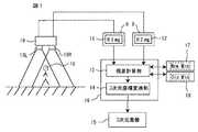
図1には、本発明にかかる画像処理装置の一例とされる3次元座標計測システムの構成例が示される。このシステムは、特に制限されないが、人体などの被写体の位置や動線を検出して3次元画像を形成することができる。 FIG. 1 shows a configuration example of a three-dimensional coordinate measurement system as an example of an image processing apparatus according to the present invention. Although this system is not particularly limited, a three-dimensional image can be formed by detecting the position and flow line of a subject such as a human body.
図1に示される3次元座標計測システムは、特に制限されないが、ステレオカメラ19、中央処理装置(CPU)16、第1バッファ17、第2バッファ18を含む。 The three-dimensional coordinate measurement system shown in FIG. 1 includes a
上記ステレオカメラ19は、被写体10の左画像(LImg)11を得るための左カメラ19Lと、上記左カメラ19Lに対して所定の間隔を有して配置されることによって上記被写体10の右画像(RImg)12を得るための右カメラ19Rとを含む。左カメラ19Lで得られた左画像11及び右カメラ19Rで得られた右画像12は、それぞれ対応するフレームメモリ8,9を介してCPU16に取り込まれる。 The
CPU16は、所定のプログラムを実行することによって、上記ステレオカメラ19から伝達された左画像11及び右画像12についての演算処理を行う。具体的には、上記左画像11及び上記右画像12とに基づいて視差画像を得るための視差計算処理を行う視差計算部13と、この視差計算部13において得られた視差画像に対して3次元座標変換処理を施すことによって3次元画像を得るための3次元座標変換部14とが機能的に実現される。上記3次元座標変換部14における3次元座標変換処理においては、上記ステレオカメラ19におけるレンズ歪み補正データ、カメラキャリブレーションデータ、カメラ設置データ(カメラの位置、焦点処理等)が必要とされ、それらは予め3次元座標変換部14に与えられている。尚、3次元座標変換処理自体は公知の技術(例えば特許文献3など)を適用することができる。 The
第1バッファ17及び第2バッファ18は、それぞれ上記視差計算処理に使用されるワーク画像を格納するために設けられ、CPU16によってアクセス可能とされる。ここでは説明の便宜上、第1バッファ17に格納されているワーク画像を「NewMin」とし、第2バッファ18に格納されているワーク画像を「OldMin」とする。上記ワーク画像NewMin,OldMinは、上記視差計算部13での演算処理において適宜に読み出される。また、必要に応じて第1バッファ17内のワーク画像と第2バッファ18内のワーク画像との入換えが行われる。 The
図2には、上記視差計算部13で行われる視差計算処理のアルゴリズムが示される。 FIG. 2 shows an algorithm for parallax calculation processing performed by the
上記視差計算部13で視差計算処理が行われる前に、第1バッファ17内のワーク画像NewMin、及び第2バッファ18内のワーク画像OldMinは、最大画素値に初期化される。特に制限されないが、画素値が符号無しの8ビットで示される場合には、「0xFF」とされる。 Before the parallax calculation process is performed in the
また、求める視差の大きさ(ここでは「0〜I」とする)に対応する数だけ、画素値変換のためのルックアップテーブルが用意される。例えば、視差0に対応するルックアップテーブル、視差1に対応するルックアップテーブル、視差2に対応するルックアップテーブル、視差3に対応するルックアップテーブルのように、複数のルックアップテーブル21が用意される。ルックアップテーブル21は、図示されない読み出し専用メモリなどを利用して形成される。 Also, as many lookup tables for pixel value conversion as the number corresponding to the required parallax magnitude (here, “0 to I”) are prepared. For example, a plurality of lookup tables 21 are prepared such as a lookup table corresponding to
先ず、視差0の右画像12を基準にした視差画像を次のように計算する。 First, a parallax image based on the
ステップS12において、左画像11から右画像12を各画素毎引き算することによって第1差分画像を得る(SubAbs)。このステップS12の引き算結果は絶対値化される。 In step S12, the first difference image is obtained by subtracting the
ステップS13において、上記第1差分画像を所定のサイズの矩形領域毎に画素値の加算平均化処理を行う(Avrg)。上記矩形領域の大きさは任意に設定することができる。 In step S13, the first difference image is subjected to pixel value addition averaging processing for each rectangular area of a predetermined size (Avrg). The size of the rectangular area can be arbitrarily set.
ステップS14において、上記ステップS13で平均化処理された画像と、第1バッファ17内の第1ワーク画像(NewMin)とが画素毎に比較され、この比較結果に基づいて第1バッファ17内の第1ワーク画像(NewMin)の画素値が更新される。具体的には、上記ステップS13で平均化処理された画像と、第1バッファ17内の第1ワーク画像(NewMin)との画素毎の比較において小さい方の値によって第1バッファ17内の第1ワーク画像(NewMin)の画素値が置き換えられる。 In step S14, the image averaged in step S13 and the first work image (NewMin) in the
ステップS15において、第1バッファ17内の第1ワーク画像(NewMin)と、第2バッファ18内の第2ワーク画像(OldMin)の引き算が行われることで第2差分画像が形成される(Sub)。このステップS15の引き算において、「0」以下は切り捨てられる。 In step S15, a second differential image is formed by subtracting the first work image (NewMin) in the
ステップS16において、上記第2差分画像における画素値の変換処理が行われる(LUT)。この変換処理においては、現在の計算視差値「0」に対応するルックアップテーブルが使用される。現在の計算視差値「0」に対応するルックアップテーブルによれば、上記第2差分画像における画素値「0」は、そのまま「0」とされ、上記第2差分画像における「0」以外の画素値の場合も「0」に変換される。これによって視差「0」についての視差画像20が得られる。 In step S16, pixel value conversion processing in the second difference image is performed (LUT). In this conversion process, a lookup table corresponding to the current calculated parallax value “0” is used. According to the lookup table corresponding to the current calculated parallax value “0”, the pixel value “0” in the second difference image is set to “0” as it is, and pixels other than “0” in the second difference image. The value is also converted to “0”. As a result, the
次に、視差「1」についての視差画像が次のように求められる。 Next, a parallax image for parallax “1” is obtained as follows.
第1バッファ17内の第1ワーク画像(NewMin)と、第2バッファ18内の第2ワーク画像(OldMin)との入換えが行われ、左画像11が、現在計算中の視差「1」に相当する画素だけ左にシフトされた状態で、上記ステップS12〜S16までの処理が再度実行される。このとき、ステップS16での変換処理では、現在の計算視差値「1」に対応するルックアップテーブルが使用される。現在の計算視差値「1」に対応するルックアップテーブルによれば、上記第2差分画像における画素値「0」は、そのまま「0」とされ、上記第2差分画像における「0」以外の画素値は「1」に変換される。これによって視差「1」についての視差画像20が得られる。 The first work image (NewMin) in the
次に、視差「2」についての視差画像が次のように求められる。 Next, a parallax image for parallax “2” is obtained as follows.
再び第1バッファ17内の第1ワーク画像(NewMin)と、第2バッファ18内の第2ワーク画像(OldMin)との入換えが行われ、左画像11が、現在計算中の視差「2」に相当する画素だけ左にシフトされた状態で、上記ステップS12〜S16までの処理が再度実行される。このとき、ステップS16での変換処理では、現在の計算視差値「2」に対応するルックアップテーブルが使用される。現在の計算視差値「2」に対応するルックアップテーブルによれば、上記第2差分画像における画素値「0」は、そのまま「0」とされ、上記第2差分画像における「0」以外の画素値は「2」に変換される。これによって視差「2」についての視差画像20が得られる。 The first work image (NewMin) in the
このようにして、求めようとする視差(これを「i」とする)までの視差画像20を得ることができる。尚、現在の計算視差値「i」に対応するルックアップテーブルによれば、上記第2差分画像における画素値「0」は、そのまま「0」とされ、上記第2差分画像における「0」以外の画素値は「i」に変換される。これによって視差「i」についての視差画像20が得られる。 In this way, it is possible to obtain the
上記例によれば、以下の作用効果を得ることができる。 According to the above example, the following operational effects can be obtained.
(1)ステップS12での引き算処理、ステップS13での加算平均化処理、ステップS14での比較処理、ステップS15での引き算処理、及びステップS16での画素値変換処理は、高度な3次元演算処理ではなく、一般的な処理能力を有するCPUで十分に処理可能であるため、CPUの性能に殆ど影響されずに視差計算を行うことができる。 (1) Subtraction processing in step S12, addition averaging processing in step S13, comparison processing in step S14, subtraction processing in step S15, and pixel value conversion processing in step S16 are advanced three-dimensional arithmetic processing. Instead, the processing can be sufficiently performed by a CPU having a general processing capability, so that the parallax calculation can be performed with almost no influence on the performance of the CPU.
(2)視差計算部13での演算処理においては、フレームメモリ8,9から左画像11及び右画像12を取り込むことによってフレーム単位で処理している。換言すれば、視差計算部13での演算処理の単位がフレームとされる。処理の単位が8×8画素の小ブロックとされる場合のようにフレームメモリを頻繁にアクセスして画像データを取り込む必要が無いので、その分、フレームメモリのアクセス回数が少なくて済む。 (2) In the arithmetic processing in the
(3)上記(1)及び(2)の作用効果により、視差画像20を得るまでの時間短縮を図ることができる。 (3) The time until the
以上本発明者によってなされた発明を具体的に説明したが、本発明はそれに限定されるものではなく、その要旨を逸脱しない範囲で種々変更可能であることはいうまでもない。 Although the invention made by the present inventor has been specifically described above, the present invention is not limited thereto, and it goes without saying that various changes can be made without departing from the scope of the invention.
例えば、上記の例では、左画像11が、現在計算中の視差に相当する画素だけ左にシフトされた状態で、上記ステップS12〜S16までの処理が実行される場合について説明したが、図3に示されるように、右画像12が、現在計算中の視差に相当する画素だけ右にシフトされた状態で(ステップS17)、上記ステップS12〜S16までの処理が実行されるようにしても良い。尚、図3においてステップS12〜S16までの処理は、図2に示される場合と同一とされるため、その詳細な説明を省略する。 For example, in the above example, a case has been described in which the processing from step S12 to step S16 is performed in a state where the
以上の説明では主として本発明者によってなされた発明をその背景となった利用分野である3次元座標計測システムに適用した場合について説明したが、本発明はそれに限定されるものではなく、画像処理装置に広く適用することができる。 In the above description, the case where the invention made mainly by the present inventor is applied to the three-dimensional coordinate measuring system which is a field of use as the background has been described. However, the present invention is not limited thereto, and the image processing apparatus is not limited thereto. Can be widely applied to.
本発明は、少なくとも視差計算処理を行う視差計算部を含むことを条件に適用することができる。 The present invention can be applied on condition that at least a parallax calculation unit that performs parallax calculation processing is included.
8,9 フレームメモリ
11 左画像
12 右画像
13 視差計算部
14 3次元座標変換部
15 3次元画像
16 CPU
17 第1バッファ
18 第2バッファ
19 ステレオカメラ
19L 左カメラ
19R 右カメラ
20 視差画像
21 ルックアップテーブル8, 9
17
Claims (5)
Translated fromJapaneseそれぞれ上記視差計算処理に使用されるワーク画像を保持可能な第1バッファ及び第2バッファと、を含み、
上記視差計算部での視差計算処理は、
上記第1画像と上記第2画像とを引き算して第1差分画像を得る第1処理と、
上記第1差分画像の画素値を加算平均する第2処理と、
上記第2処理で加算平均された画像と上記第1バッファ内のワーク画像とを比較し、小さい方の値によって上記第1バッファ内のワーク画像の画素値を更新する第3処理と、
上記第1バッファ内のワーク画像と、上記第2バッファ内のワーク画像との引き算により第2差分画像を得る第4処理と、
視差との関係で予め形成されたルックアップテーブルを用いて上記第2差分画像の画素値を変換することによって視差画像を得る第5処理と、を含む画像処理装置。Parallax calculation for performing parallax calculation processing by capturing a first image obtained by a first camera and a second image obtained by a second camera arranged at a predetermined interval with respect to the first camera And
A first buffer and a second buffer each capable of holding a work image used for the parallax calculation process,
The parallax calculation processing in the parallax calculation unit is as follows:
A first process of subtracting the first image and the second image to obtain a first difference image;
A second process for averaging the pixel values of the first difference image;
A third process for comparing the image averaged in the second process with the work image in the first buffer and updating the pixel value of the work image in the first buffer with a smaller value;
A fourth process for obtaining a second difference image by subtraction of the work image in the first buffer and the work image in the second buffer;
An image processing apparatus comprising: a fifth process for obtaining a parallax image by converting a pixel value of the second difference image using a look-up table formed in advance in relation to parallax.
Priority Applications (1)
| Application Number | Priority Date | Filing Date | Title |
|---|---|---|---|
| JP2005050021AJP2006236022A (en) | 2005-02-25 | 2005-02-25 | Image processor |
Applications Claiming Priority (1)
| Application Number | Priority Date | Filing Date | Title |
|---|---|---|---|
| JP2005050021AJP2006236022A (en) | 2005-02-25 | 2005-02-25 | Image processor |
Publications (1)
| Publication Number | Publication Date |
|---|---|
| JP2006236022Atrue JP2006236022A (en) | 2006-09-07 |
Family
ID=37043599
Family Applications (1)
| Application Number | Title | Priority Date | Filing Date |
|---|---|---|---|
| JP2005050021APendingJP2006236022A (en) | 2005-02-25 | 2005-02-25 | Image processor |
Country Status (1)
| Country | Link |
|---|---|
| JP (1) | JP2006236022A (en) |
Cited By (3)
| Publication number | Priority date | Publication date | Assignee | Title |
|---|---|---|---|---|
| JPH0735158A (en)* | 1993-07-22 | 1995-02-03 | Shinko Electric Co Ltd | Cooling structure of marine hydraulic clutch unit |
| JP2008236642A (en)* | 2007-03-23 | 2008-10-02 | Hitachi Ltd | Object tracking device |
| JP2014178190A (en)* | 2013-03-14 | 2014-09-25 | Ricoh Co Ltd | Stereo camera |
Citations (1)
| Publication number | Priority date | Publication date | Assignee | Title |
|---|---|---|---|---|
| JP2000512790A (en)* | 1997-04-15 | 2000-09-26 | インターバル リサーチ コーポレイション | Data processing system and method |
- 2005
- 2005-02-25JPJP2005050021Apatent/JP2006236022A/enactivePending
Patent Citations (1)
| Publication number | Priority date | Publication date | Assignee | Title |
|---|---|---|---|---|
| JP2000512790A (en)* | 1997-04-15 | 2000-09-26 | インターバル リサーチ コーポレイション | Data processing system and method |
Cited By (3)
| Publication number | Priority date | Publication date | Assignee | Title |
|---|---|---|---|---|
| JPH0735158A (en)* | 1993-07-22 | 1995-02-03 | Shinko Electric Co Ltd | Cooling structure of marine hydraulic clutch unit |
| JP2008236642A (en)* | 2007-03-23 | 2008-10-02 | Hitachi Ltd | Object tracking device |
| JP2014178190A (en)* | 2013-03-14 | 2014-09-25 | Ricoh Co Ltd | Stereo camera |
Similar Documents
| Publication | Publication Date | Title |
|---|---|---|
| EP3565739B1 (en) | Rear-stitched view panorama for rear-view visualization | |
| JP6891954B2 (en) | Object detection device, object detection method, and program | |
| US20170339397A1 (en) | Stereo auto-calibration from structure-from-motion | |
| JP2009265783A (en) | Driving supporting system and vehicle | |
| JP2005072888A (en) | Image projection method and image projection device | |
| US10300854B2 (en) | Apparatus and method of generating top-view image | |
| EP3633606B1 (en) | Information processing device, information processing method, and program | |
| GB2567530A (en) | Virtual reality parallax correction | |
| CN109447901B (en) | Panoramic imaging method and device | |
| JP2012198077A (en) | Stereo camera device and parallax image generating method | |
| JP5624370B2 (en) | Moving body detection apparatus and moving body detection method | |
| JPWO2014076769A1 (en) | Detection apparatus, method and program | |
| JP2022132063A (en) | Pose determination method and device for augmented reality providing device | |
| JP2008085710A (en) | Driving support system | |
| JP2022506061A (en) | Rolling Shutter Correction for images / videos using convolutional neural networks in applications for image / video SFM / SLAM | |
| WO2019198399A1 (en) | Image processing device and method | |
| US10943334B2 (en) | Method and system for representation of vehicle surroundings with reduced artefacts | |
| JP6188860B1 (en) | Object detection device | |
| US20130142388A1 (en) | Arrival time estimation device, arrival time estimation method, arrival time estimation program, and information providing apparatus | |
| JP6407596B2 (en) | Image processing apparatus and driving support system | |
| JP6444981B2 (en) | Image processing apparatus, image processing method, and image processing program | |
| WO2020003764A1 (en) | Image processing device, moving apparatus, method, and program | |
| JP2017078692A (en) | Drive assisting information output device and drive assisting information output method | |
| JP2011209070A (en) | Image processor | |
| JP2006236022A (en) | Image processor |
Legal Events
| Date | Code | Title | Description |
|---|---|---|---|
| A621 | Written request for application examination | Free format text:JAPANESE INTERMEDIATE CODE: A621 Effective date:20080221 | |
| A977 | Report on retrieval | Free format text:JAPANESE INTERMEDIATE CODE: A971007 Effective date:20101108 | |
| A131 | Notification of reasons for refusal | Free format text:JAPANESE INTERMEDIATE CODE: A131 Effective date:20101124 | |
| A02 | Decision of refusal | Free format text:JAPANESE INTERMEDIATE CODE: A02 Effective date:20110317 |