JP2006224904A - Vehicle control device - Google Patents
Vehicle control deviceDownload PDFInfo
- Publication number
- JP2006224904A JP2006224904AJP2005044021AJP2005044021AJP2006224904AJP 2006224904 AJP2006224904 AJP 2006224904AJP 2005044021 AJP2005044021 AJP 2005044021AJP 2005044021 AJP2005044021 AJP 2005044021AJP 2006224904 AJP2006224904 AJP 2006224904A
- Authority
- JP
- Japan
- Prior art keywords
- road
- vehicle
- branch
- control
- information
- Prior art date
- Legal status (The legal status is an assumption and is not a legal conclusion. Google has not performed a legal analysis and makes no representation as to the accuracy of the status listed.)
- Pending
Links
Images


Landscapes
- Navigation (AREA)
- Control Of Driving Devices And Active Controlling Of Vehicle (AREA)
- Traffic Control Systems (AREA)
Abstract
Translated fromJapaneseDescription
Translated fromJapanese本発明は、車両の走行を支援するための各種制御を行う車両制御装置に関する。 The present invention relates to a vehicle control apparatus that performs various types of control for supporting the traveling of a vehicle.
従来から、車両の現在位置情報と、ナビゲーションシステムに記憶された道路情報とに基づいて、道路分岐点を起点に発生する複数の分岐路の中から進行する方向を推定し、推定された分岐路の道路情報に基づいて車両制御を行う車両制御装置が知られている(例えば、特許文献1参照)。また、自車前方の交差点(道路分岐点)から分岐する複数の分岐路のうち、走行難易度の最も低い分岐路(自車が進行する道路との交差角が最も小さい分岐路)と、該走行難易度の最も低い分岐路上のカーブとを対象として通過可否の判定をし、通過不可判定の場合には車速制御や警報などの各種車両制御を行う車両制御装置が知られている(例えば、特許文献2参照)。
しかしながら、道路分岐点を起点に発生する複数の分岐路の中には、特に車両制御(典型的には、減速を促す警報や介入制動)の必要性の高い分岐路が含まれる場合がある。従って、上述の従来技術のように、単に走行の可能性が高い分岐路や、走行難易度の最も低い分岐路を走行すると想定して車両制御を行う構成では、実際に走行する分岐路が、想定していた分岐路と異なるものであり、しかも車両制御の必要性が高い分岐路であったとき、当該想定外の分岐路に対して適正な車両制御を行うための修正が困難となる。 However, the plurality of branch roads that start from the road branch point may include branch roads that have a particularly high need for vehicle control (typically, warning for prompting deceleration or intervention braking). Therefore, as in the above-described prior art, in a configuration in which vehicle control is performed on the assumption that the vehicle travels on a branch road with a high possibility of traveling or a branch road with the lowest traveling difficulty, the actually traveling branch road is When the branch road is different from the assumed branch road and the necessity of vehicle control is high, it is difficult to make corrections for performing appropriate vehicle control on the unexpected branch road.
そこで、本発明は、実際に走行する分岐路が想定と異なる分岐路であっても、当該想定外の分岐路に対して適正な車両制御を行うことができる車両制御装置の提供を目的とする。 Therefore, the present invention has an object of providing a vehicle control device that can perform appropriate vehicle control on an unforeseen branch road even if the actually traveling branch road is different from the assumed branch road. .
上記課題を解決するため、本発明の一局面によれば、車両の走行を支援するための各種制御を行う車両制御装置において、
車両の現在位置情報と所与の地図情報とに基づいて、進行方向前方にある道路分岐点を検出する手段と、
検出した道路分岐点からの分岐後の複数の分岐路に対して、各分岐路に係る道路情報に基づいて、各分岐路を走行したと想定した場合の制御必要度を評価する手段とを備え、
前記評価した最も高い制御必要度の分岐路を走行すると想定して、前記道路分岐点より手前の区間での制御態様を決定することを特徴とする、車両制御装置が提供される。In order to solve the above-described problem, according to one aspect of the present invention, in a vehicle control apparatus that performs various controls for supporting driving of a vehicle,
Means for detecting a road junction ahead of the direction of travel based on the current position information of the vehicle and the given map information;
Means for evaluating the degree of control necessity when it is assumed that the vehicle has traveled on each branch road based on road information relating to each branch road for a plurality of branch roads after branching from the detected road branch point ,
Provided is a vehicle control device that determines a control mode in a section before the road branch point on the assumption that the vehicle travels on the evaluated branch road with the highest degree of control necessity.
本局面において、検出した道路分岐点からの分岐後の複数の分岐路に対して、車両の走行状態を表す走行状態情報及び/又は道路分岐点前後の道路情報に基づいて、各分岐路を走行する可能性を評価する走行可能性評価手段を更に備え、
前記走行可能性が所定値以上となる分岐路のうちの、前記制御必要度の最も高い分岐路を走行すると想定して、前記道路分岐点より手前の区間での制御態様を決定することとしてもよい。In this aspect, for each of a plurality of branch roads after branching from the detected road branch point, the vehicle travels on each branch road based on the driving state information indicating the driving state of the vehicle and / or road information before and after the road branch point. The vehicle further includes a traveling possibility evaluation means for evaluating the possibility of
Assuming that the vehicle travels on the branch road having the highest degree of control necessity among the branch roads where the travel possibility becomes a predetermined value or more, the control mode in the section before the road branch point may be determined. Good.
本発明によれば、実際に走行する分岐路が想定と異なる分岐路であっても、当該想定外の分岐路に対して適正な車両制御を行うことができる車両制御装置を得ることができる。 According to the present invention, it is possible to obtain a vehicle control device that can perform appropriate vehicle control on an unforeseen branch road even if the actually traveling branch road is a branch road different from the assumed one.
以下、図面を参照して、本発明を実施するための最良の形態の説明を行う。 The best mode for carrying out the present invention will be described below with reference to the drawings.
図1は、本発明による車両制御装置の一実施例を示すシステム構成図である。本実施例の車両制御装置は、統合マネージャ10を備える。統合マネージャ10は、通常的なECU(電子制御ユニット)と同様、図示しないバスを介して互いに接続されたCPU、ROM、及びRAM等からなるマイクロコンピュータとして構成されている。 FIG. 1 is a system configuration diagram showing an embodiment of a vehicle control apparatus according to the present invention. The vehicle control device of this embodiment includes an integrated
統合マネージャ10は、以下で詳説する如く、地図データベース20内に格納されている地図情報(後述する)等に基づいて、車両進行方向前方に迫る道路分岐点を把握し、当該道路分岐点及びそこからの分岐路を適切に通過できるように、必要に応じて各種制御対象デバイスに制御指示を出して車両を制御する制御装置である。 As will be described in detail below, the integrated
上記の制御対象デバイスは、ブレーキ、エンジンやトランスミッションのような車両の運動を制御する装置のみならず、ディスプレイやオーディオのような警報装置として機能できる装置を含む。従って、統合マネージャ10からこれらの制御対象デバイスに送信される制御指示には、運動制御装置に対する加減速指示や、警報装置に対する加減速を促す警報出力指示が含まれる。 The devices to be controlled include not only devices that control the movement of the vehicle such as brakes, engines and transmissions, but also devices that can function as alarm devices such as displays and audio. Therefore, the control instruction transmitted from the integrated
統合マネージャ10には、CAN(controller area network)などの適切なバスを介して、上記の制御デバイスの他、車両内の各種の電子部品(車速センサのような各種センサや各種ECU)が接続される。例えば、統合マネージャ10には、ナビゲーション装置の主要機能を実現するナビゲーションECU20が接続される。ナビゲーションECU20は、マイクロコンピュータで構成され、CPU、ROM、RAM、I/O等を備えている。 In addition to the control device described above, various electronic components in the vehicle (various sensors such as vehicle speed sensors and various ECUs) are connected to the integrated
ナビゲーションECU20には、DVD、CD−ROM等の記録媒体上に地図データを保有する地図データベース22や、地図表示や経路案内表示を映像により出力する液晶ディスプレイ等の表示装置24、ユーザインターフェースとなるタッチパネル等の操作入力部26等が接続されている。 The navigation ECU 20 includes a
ナビゲーションECU20には、自車位置検出手段28を備えている。自車位置検出手段28は、GPS(Global Positioning System)受信機、ビーコン受信機及びFM多重受信機や、車速センサやジャイロセンサ等の各種センサを含む。自車位置検出手段28は、GPS受信機によりGPSアンテナを介してGPS衛星が出力するGPS信号を受信する。自車位置検出手段28は、GPS信号を所定形式の信号に変換してナビゲーションECU20に供給する。ナビゲーションECU20は、GPS信号や各種センサから供給された信号に基づいて、現在の車両位置及び車両方位を演算する。 The
地図データベース22には、地図データが格納されている。地図データには、通常的なものと同様、道路分岐点(交差点)に対応するノードの座標情報、高速道路の合流点/分岐点に各々対応する各ノードの座標情報、隣接するノードを接続するリンク情報、各リンクに対応する道路の幅員情報、各リンクに対応する国道・県道・高速道路等の道路種別、各リンクの通行規制情報及び各リンク間の通行規制情報等の各種道路情報が含まれている。 The
地図データベース22には、更に、コーナの形状に関する道路情報としてコーナ情報が含まれている。コーナは、典型的には、クロソイド曲線(緩和曲線)の形状を有する入口側のクロソイド区間、一定曲率区間、及び、出口側のクロソイド区間からなる。従って、コーナ情報は、各クロソイド区間の開始点及び終了点(座標値)、各一定曲率区間の開始点及び終了点、一定曲率区間の曲率半径R[m]、カントα[%]、旋回角度θ[rad]、クロソイド区間の区間長LC[m]及び一定曲率区間の区間長LF[m]若しくはその類を含んでよい。The
ここで、一般的なナビゲーション装置の地図データには、これらのコーナ情報は含まれていない。典型的には、コーナは点情報の集合として管理されている。かかる地図データに対しては、これらの点情報から上記のコーナ情報(曲率半径Rや区間長LF、LCなど)が予め算出・生成され、これらがコーナ情報として地図データベース22に格納されてもよい。Here, such corner information is not included in the map data of a general navigation apparatus. Typically, a corner is managed as a set of point information. For such map data, the above corner information (curvature radius R, section length LF , LC, etc.) is calculated and generated in advance from these point information, and these are stored in the
或いは、コーナ情報は、一般的なナビゲーション装置の地図データに代えて若しくはそれに加えて、詳細な実測データを用いて導出されたものであってもよく、若しくは、当該コーナを実走行した際に得られる横加速度データやヨー角データ(センサ出力)に基づいて逆算的に導出されたものであってもよい。前者の場合として、具体的には各種入手可能な工事図面から曲率情報を導出してもよく、又は、航空写真から道路のセンターラインに対して形状点列を打点し、当該打点データを解析して曲率情報を導出してもよい。 Alternatively, the corner information may be derived using detailed measured data instead of or in addition to the map data of a general navigation device, or obtained when the corner is actually traveled. It may be derived inversely based on the obtained lateral acceleration data or yaw angle data (sensor output). Specifically, in the former case, curvature information may be derived from various available construction drawings, or from aerial photographs, shape point sequences are scored on the center line of the road, and the corresponding dot data is analyzed. Thus, curvature information may be derived.
尚、地図データベース22内にこれらのコーナ情報を事後的に追記・更新する構成の場合には、地図データベース22はハードディスクのような書き込み可能な記録媒体により構成されてよい。 In the case of a configuration in which the corner information is added / updated later in the
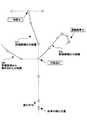
次に、本実施例による統合マネージャ10(及びナビゲーションECU20)により実現される車両制御について説明する。図2は、本実施例に係るナビゲーションECU20及び統合マネージャ10の処理を示すフローチャートである。ここでは、図3に示す道路環境において車両進行方向前方に道路分岐点Xが出現した場合を想定する。 Next, vehicle control realized by the integrated manager 10 (and the navigation ECU 20) according to this embodiment will be described. FIG. 2 is a flowchart illustrating processing of the
先ず、ステップ100として、ナビゲーションECU20は、車両の現在位置情報と地図データベース22内の地図データに基づいて、進行方向前方の所定距離内に道路分岐点が存在するか否かを判定する。尚、本明細書及び添付の特許請求の範囲において、用語“道路分岐点”とは、典型的には、走行可能な車線が2以上方向に分かれる地点であり、典型的には交差点を指すが、高速道路の分岐点などのような、分岐直後の方向は略同じであるが実質的には分岐である地点も含むものとする。 First, as
上記ステップ100において道路分岐点が検出された場合、ステップ110以降の処理に進む。本例では、図3に示す道路分岐点Xが検出されるものとする。 If a road junction is detected in
ステップ110では、ナビゲーションECU20は、道路分岐点Xを起点として発生する複数の分岐路の中から、評価候補となる分岐路を選択する。この評価候補の選別は、以下の処理で制御必要度の評価を受けるに値する分岐路のみを選別する趣旨で実行されるものであり、例えば検出した道路分岐点前後での道路形状、現在又は現在までの車両の走行状態やドライバの運転状態等に基づくものであってよい。例えば、一方通行などにより走行できない分岐路や、車両を90度以上旋回しなければ走行できないような分岐路といったような、現在の走行路からの走行が物理的に不能ないし困難であるか若しくは走行の可能性の非常に小さい分岐路が、評価候補から排除されてよい。本例では、図3に示す分岐路D0〜D2の中から、分岐路D1、D2が評価候補として選別され、分岐路D0が評価候補から除外されるものとする。 In step 110, the
このようにして評価候補となる分岐路が選別されると、ナビゲーションECU20は、当該選別した分岐路に係る道路情報を地図データベース22内から検索して取り出し、当該取り出した道路情報を統合マネージャ10に送信する。このようにしてナビゲーションECU20から道路情報が供給されると、ステップ120以降において、統合マネージャ10は、以下で詳説するように、道路分岐点手前の道路区間において、各分岐路の状態に応じた適切な車両制御を実行していく。 When the branch road as the evaluation candidate is selected in this way, the
以下、前提として、統合マネージャ10には、ナビゲーションECU20の自車位置検出手段28により検出される自車位置情報及び車速センサからの自車速情報が、所定周期毎に供給されており、統合マネージャ10は、常時、最新の車両位置及び車速を算出・把握しているものとする。 Hereinafter, as a premise, the
先ず、ステップ120では、統合マネージャ10は、評価候補とされた各分岐路に対して、制御必要度を評価する。ここで、分岐路に対する制御必要度は、当該分岐路の区間を安定して走行させるために必要な目標制御値に対応し、例えば介入制動の場合、当該分岐路上のある地点である目標速度まで減速するのに必要な目標減速度又はその類であってよい。以下では、説明上、制御必要度とは、目標減速度とする。 First, in
本例では、評価候補として選別された分岐路D1、D2に対して制御必要度が評価される。先ず一時停止点を含む分岐路D1に対しては、当該一時停止点で車速ゼロを実現する必要があるため、比較的高い制御必要度が付与される。尚、分岐路D1が一時停止点を含むことは、地図データベース22内の地図データに基づいて判断されてよい。但し、地図データベース22内の地図データにかかる道路情報が含まれていない場合、例えば信号機の無い交差点を簡易的に一時停止点と看做してもよく、或いは、当該一時停止点で交差する道路との優先関係や道路種別の対比結果に基づいて、一時停止点が存在するか否かを推定してもよい。後者のような推定方法の詳細は、例えば特開2004−86363号公報に開示されており、かかる方法が採用されてよい。また、CCDカメラなどのような撮像手段を搭載する車両においては、過去に走行した道路分岐点で実際に取得された正確な道路情報が、地図データベース22内に追加的に格納され、次回以降の走行の際に利用されてもよい。 In this example, the degree of control necessity is evaluated for the branch paths D1 and D2 selected as evaluation candidates. First, for the branch road D1 including the temporary stop point, since it is necessary to realize the vehicle speed zero at the temporary stop point, a relatively high degree of control necessity is given. It may be determined based on the map data in the
コーナを含む分岐路D2に対しては、当該コーナの入口で所定の車速を実現する必要があるものの、車速ゼロを実現する必要がある分岐路D1に比べて低い制御必要度が付与される。ここで、分岐路D2がコーナを含むことは、地図データベース22内の地図データに基づいて判断されてよい。但し、曲率半径が一定基準より大きいコーナのような、制御の必要性の乏しいコーナは除外されてよい。この観点から、コーナを含む分岐路に対しては、制御必要度は、含まれるコーナの曲率半径やコーナ手前の減速区間の長さなどに基づいて、段階的に評価されてよい。また、複数のコーナを連続して含む場合には、かかる連続コーナの最も急なコーナに関する情報に基づいて、制御必要度が評価されてもよい。 Although it is necessary to achieve a predetermined vehicle speed at the entrance of the corner, the branch D2 including the corner is given a lower control necessity than the branch D1 where the vehicle speed needs to be zero. Here, it may be determined based on the map data in the
続くステップ130では、統合マネージャ10は、各分岐路に対して評価した制御必要度のうち最も高い制御必要度を特定・選択し、続くステップ140では、統合マネージャ10は、当該最も高い制御必要度を基準として、最終的な目標制御値を決定する。本例では、上述の如く分岐路D1に対する制御必要度が分岐路D2に対する制御必要度よりも大きいので、分岐路D1に対する制御必要度を基準として(即ち車両が分岐路D1を走行すると想定して)、最終的な目標制御値が決定されることになる。具体的には、現在の車両位置から一時停止点までの距離と、現在の車速とに基づいて、一時停止点で車速ゼロを実現するために必要な目標減速度が算出され、当該目標減速度が最終的な目標制御値とされる。 In the subsequent step 130, the
一方、上記ステップ100において所定距離内に道路分岐点が存在しないと判定された場合には、統合マネージャ10は、通常通り、現在の走行路に直接関連する道路情報に基づいて、最終的な目標制御値を決定する(ステップ150)。例えば、図3に示す先の例とは異なり、分岐路D0やD1がなく、道路分岐点Xが存在しない場合、統合マネージャ10は、(正確には、“分岐路”といえないが)分岐路D2に対する制御必要度を基準として、最終的な目標制御値を決定することになる。 On the other hand, if it is determined in
このようにして最終的な目標制御値を決定すると、統合マネージャ10は、ステップ160において、当該最終的な目標制御値に基づいて、必要に応じて車両制御を実行する。車両制御は、例えば減速を促す各種警報や介入制動のような車両制御であってよく、この場合、例えば最終的な目標制御値である目標減速度が所定値以上となったときに(即ち所定基準以上の減速が必要となったときに)、各種警報及び/又は介入制動が実行されてよい。尚、本発明は、特に警報や介入制動のような車両制御の詳細によって限定されるものではなく、如何なる適切な車両制御に対しても適用可能である。 When the final target control value is determined in this manner, the
本ステップ160において、車両が道路分岐点を実際に通過する等して実際の車両の走行路が確定した後は、当然ながら、当該実際に走行している分岐路に係る目標制御値に基づいて、車両制御が実行されることになる。従って、先の例で、仮に実際の車両の走行路が分岐路D1でなく分岐路D2であると判明した場合、統合マネージャ10は、分岐路D2に対する制御必要度を基準として、最終的な目標制御値を決定することになる。この場合でも、本実施例によれば、分岐路D2に対する制御必要度が、上述の如く、分岐路D1に対する制御必要度に比して低いので、分岐路D2を走行時に急な減速を要求等する必要が無く、適正な車両制御を実現することが可能である。 In this step 160, after the actual travel path of the vehicle is determined by, for example, the vehicle actually passing through the road branch point, of course, based on the target control value relating to the actual travel path. Then, vehicle control is executed. Therefore, in the above example, if it is determined that the actual vehicle travel path is the branch path D2 instead of the branch path D1, the
以上のように本実施例によれば、車両前方の道路分岐点が検出された段階で、当該道路分岐点から派生する複数の分岐路のうち、走行可能性のある分岐路を適切に選別し、当該選別した分岐路に対してそれぞれ評価した制御必要度のうち、最も高い制御必要度に基づいて車両制御が実行されるので、仮に実際に走行する分岐路が想定と異なる分岐路であっても、当該想定外の分岐路に対して適正な車両制御を行うことができる。 As described above, according to the present embodiment, when a road branch point ahead of the vehicle is detected, a branch road having a possibility of traveling is appropriately selected from a plurality of branch roads derived from the road branch point. Since the vehicle control is executed based on the highest control necessity among the control necessity evaluated for each of the selected branch roads, the branch road actually traveled is a branch road different from the assumed one. In addition, appropriate vehicle control can be performed on the unexpected branch road.
尚、本実施例の変形例として、上述の制御必要度(目標制御値)が、より厳密に求められてもよい。例えば、コーナを含む分岐路D2に対しては、コーナにおける一定曲率区間XFの曲率半径R及びカントαを用いて、当該コーナ走行時の目標速度Vtg[m/s]を算出し、次いで、現在の車両位置や車速、コーナ入口までの距離情報に基づいて、目標速度Vtgをコーナ入口で実現するのに必要な目標減速度を算出してもよい。具体的には、統合マネージャ10は、現在の車速をV0[m/s]として、コーナの入口側クロソイド区間の開始点で目標速度Vtgとなるように減速可能区間内で減速する場合の目標減速度[m/s2]を算出する。この算出では、簡易的に現在の車速V0が維持されるものと仮定してもよく、或いは、現在までの車速の履歴に基づいて推定可能な以後の加減速態様が加味されてもよい。この際、目標速度Vtgは、所定の横加速度(旋回横加速度)の許容限度値をGy[m/s2]としたとき、Gy=Vtg2/R+α・g/100なる関係に基づいて、Vtg={R(Gy−α・g/100)}1/2により導出されてよい(gは重力加速度)。尚、許容限度値Gyは、車種毎に異なる走行性能等の相違に応じて適宜設定される設計値であるが、可変値であってよく、例えば安全性を重視するユーザに対しては下方修正されてもよい。目標速度Vtgは、コーナ毎に予め生成されていてもよく、この場合、各コーナの目標速度Vtgは、統合マネージャ10のアクセス可能なメモリに記憶されていてもよく、若しくは、統合マネージャ10に道路情報の一部として供給されても良い。一方、一時停止点を含む分岐路D1に対しては、現在の車両位置や車速、現在の車両位置から一時停止点までの距離に基づいて、一時停止点で車速ゼロを実現するために必要な目標減速度を算出してもよい。かかる変形例では、上述の如く求めた2つの目標減速度の大きい方に基づいて車両制御を行うこととすればよい。尚、本変形例において、制御必要度(目標制御値)は、上述の各地点(一時停止点又はコーナ入口)での目標速度に基づいて、道路分岐点Xまでに必要な目標減速度が算出されてもよい。As a modification of the present embodiment, the control necessity (target control value) described above may be obtained more strictly. For example, for the branch path D2 including the corner, the target speed Vtg [m / s] at the time of corner traveling is calculated using the radius of curvature R and the cant α of the constant curvature section XF at the corner, A target deceleration required to realize the target speed Vtg at the corner entrance may be calculated based on the current vehicle position, vehicle speed, and distance information to the corner entrance. Specifically, the
以上、本発明の好ましい実施例について詳説したが、本発明は、上述した実施例に制限されることはなく、本発明の範囲を逸脱することなく、上述した実施例に種々の変形及び置換を加えることができる。 The preferred embodiments of the present invention have been described in detail above. However, the present invention is not limited to the above-described embodiments, and various modifications and substitutions can be made to the above-described embodiments without departing from the scope of the present invention. Can be added.
例えば、上述の実施例では、代表的な例としてコーナや一時停止線に基づいて制御必要度を評価しているが、分岐路における制限速度や渋滞情報、工事情報、車線・幅員情報のような各種道路情報を因子として制御必要度を評価・補正することも可能である。 For example, in the above-described embodiment, the necessity of control is evaluated based on corners and temporary stop lines as a representative example. However, such as speed limit on a branch road, traffic information, construction information, lane / width information, etc. It is also possible to evaluate and correct the control necessity using various road information as a factor.
また、上述の実施例は、主に車両の減速度を調整する車両減速制御に関するものであるが、本発明は、プリクラッシュシートベルトのような直接的に車両の運動に影響を与えない他の制御に対しても適用可能である。また、減速制御だけでなく、事故回避操舵制御などを適用することも可能である。 The above-described embodiment mainly relates to vehicle deceleration control for adjusting the deceleration of the vehicle, but the present invention does not directly affect the motion of the vehicle such as a pre-crash seat belt. It can also be applied to control. Moreover, not only deceleration control but also accident avoidance steering control can be applied.
また、上述の実施例において、ナビゲーション装置でルート案内がなされている場合には、ルート案内に反する分岐路に係る制御必要度に対しては、相対的に小さく評価される方向に重み付けをしてもよい。 Further, in the above-described embodiment, when route guidance is provided by the navigation device, the control necessity degree related to the branch road contrary to the route guidance is weighted in the direction that is evaluated to be relatively small. Also good.
また、上述の実施例では、ナビゲーションECU20及び統合マネージャ10が別個独立のハードウェア構成となっているが、ナビゲーションECU20の機能が統合マネージャ10に組み込まれてもよい。 In the above-described embodiment, the
10 統合マネージャ
20 ナビゲーションECU
22 地図データベース
24 表示装置
26 操作入力部
28 自車位置検出手段10
22
Claims (2)
Translated fromJapanese車両の現在位置情報と所与の地図情報とに基づいて、進行方向前方にある道路分岐点を検出する手段と、
検出した道路分岐点からの分岐後の複数の分岐路に対して、各分岐路に係る道路情報に基づいて、各分岐路を走行したと想定した場合の制御必要度を評価する手段とを備え、
前記評価した最も高い制御必要度の分岐路を走行すると想定して、前記道路分岐点より手前の区間での制御態様を決定することを特徴とする、車両制御装置。In a vehicle control apparatus that performs various controls for supporting the running of a vehicle,
Means for detecting a road junction ahead of the direction of travel based on the current position information of the vehicle and the given map information;
Means for evaluating the degree of control necessity when it is assumed that the vehicle has traveled on each branch road based on road information relating to each branch road for a plurality of branch roads after branching from the detected road branch point ,
A vehicle control device that determines a control mode in a section before the road branch point on the assumption that the vehicle travels on the evaluated branch road with the highest degree of control necessity.
前記走行可能性が所定値以上となる分岐路のうちの、前記制御必要度の最も高い分岐路を走行すると想定して、前記道路分岐点より手前の区間での制御態様を決定することを特徴とする、請求項1に記載の車両制御装置。For a plurality of branch roads after branching from the detected road branch point, the possibility of traveling on each branch road based on the driving state information indicating the driving state of the vehicle and / or the road information before and after the road branch point. The vehicle further comprises a traveling possibility evaluation means for evaluating
The control mode in the section before the road branch point is determined on the assumption that the vehicle travels on the branch road with the highest degree of control necessity among the branch roads where the travel possibility becomes a predetermined value or more. The vehicle control device according to claim 1.
Priority Applications (1)
| Application Number | Priority Date | Filing Date | Title |
|---|---|---|---|
| JP2005044021AJP2006224904A (en) | 2005-02-21 | 2005-02-21 | Vehicle control device |
Applications Claiming Priority (1)
| Application Number | Priority Date | Filing Date | Title |
|---|---|---|---|
| JP2005044021AJP2006224904A (en) | 2005-02-21 | 2005-02-21 | Vehicle control device |
Publications (1)
| Publication Number | Publication Date |
|---|---|
| JP2006224904Atrue JP2006224904A (en) | 2006-08-31 |
Family
ID=36986624
Family Applications (1)
| Application Number | Title | Priority Date | Filing Date |
|---|---|---|---|
| JP2005044021APendingJP2006224904A (en) | 2005-02-21 | 2005-02-21 | Vehicle control device |
Country Status (1)
| Country | Link |
|---|---|
| JP (1) | JP2006224904A (en) |
Cited By (5)
| Publication number | Priority date | Publication date | Assignee | Title |
|---|---|---|---|---|
| FR2940428A1 (en)* | 2008-12-22 | 2010-06-25 | Clarion Co Ltd | VEHICLE OPERATING SUPPORT SYSTEM AND NAVIGATION DEVICE |
| JP2012098997A (en)* | 2010-11-04 | 2012-05-24 | Aisin Aw Co Ltd | Driving support device, driving support method and driving support program |
| JP2013241146A (en)* | 2012-05-22 | 2013-12-05 | Aisin Aw Co Ltd | System, method and program of vehicle speed control |
| KR20150082429A (en)* | 2012-11-02 | 2015-07-15 | 톰톰 인터내셔날 비.브이. | Methods and systems for generating a horizon for use in an advanced driver assistance system(ADAS) |
| JP7576699B2 (en) | 2020-10-28 | 2024-10-31 | メルセデス・ベンツ グループ アクチェンゲゼルシャフト | Method for dynamically restraining an occupant fastened to a vehicle seat by a seat belt - Patents.com |
- 2005
- 2005-02-21JPJP2005044021Apatent/JP2006224904A/enactivePending
Cited By (12)
| Publication number | Priority date | Publication date | Assignee | Title |
|---|---|---|---|---|
| FR2940428A1 (en)* | 2008-12-22 | 2010-06-25 | Clarion Co Ltd | VEHICLE OPERATING SUPPORT SYSTEM AND NAVIGATION DEVICE |
| JP2010143504A (en)* | 2008-12-22 | 2010-07-01 | Hitachi Automotive Systems Ltd | Vehicle driving support system and navigation device |
| JP2012098997A (en)* | 2010-11-04 | 2012-05-24 | Aisin Aw Co Ltd | Driving support device, driving support method and driving support program |
| JP2013241146A (en)* | 2012-05-22 | 2013-12-05 | Aisin Aw Co Ltd | System, method and program of vehicle speed control |
| KR20150082429A (en)* | 2012-11-02 | 2015-07-15 | 톰톰 인터내셔날 비.브이. | Methods and systems for generating a horizon for use in an advanced driver assistance system(ADAS) |
| JP2016503533A (en)* | 2012-11-02 | 2016-02-04 | トムトム インターナショナル ベスローテン フエンノートシャップ | Method and system for generating a predictable range for use in an advanced driver assistance system (ADAS) |
| US10527432B2 (en) | 2012-11-02 | 2020-01-07 | Tomtom Navigation B.V. | Methods and systems for generating a horizon for use in an advanced driver assistance system (ADAS) |
| KR102131842B1 (en)* | 2012-11-02 | 2020-07-09 | 톰톰 네비게이션 비.브이. | Methods and systems for generating a horizon for use in an advanced driver assistance system(ADAS) |
| US11378404B2 (en) | 2012-11-02 | 2022-07-05 | Tomtom Navigation B.V. | Methods and systems for generating a horizon for use in an advanced driver assistance system (ADAS) |
| JP7576699B2 (en) | 2020-10-28 | 2024-10-31 | メルセデス・ベンツ グループ アクチェンゲゼルシャフト | Method for dynamically restraining an occupant fastened to a vehicle seat by a seat belt - Patents.com |
| US12246667B2 (en) | 2020-10-28 | 2025-03-11 | Mercedes-Benz Group AG | Method for dynamically restraining an occupant fastened into a vehicle seat with a seatbelt |
| KR102856565B1 (en) | 2020-10-28 | 2025-09-08 | 메르세데스-벤츠 그룹 아게 | Dynamic restraint method for seatbelt-wearing occupants in vehicle seats |
Similar Documents
| Publication | Publication Date | Title |
|---|---|---|
| US10704920B2 (en) | Traffic lane guidance system for vehicle and traffic lane guidance method for vehicle | |
| EP3287744B1 (en) | Route searching apparatus and route searching method | |
| US8027762B2 (en) | Driving assist apparatus | |
| JP6036371B2 (en) | Vehicle driving support system and driving support method | |
| US11685398B2 (en) | Lane based routing system for autonomous driving vehicles | |
| JP4650899B2 (en) | In-vehicle system providing safety support information | |
| US20100315217A1 (en) | Driving support device and program | |
| US20120303222A1 (en) | Driver assistance system | |
| JP6954469B2 (en) | Driving support method and driving support device | |
| JP2006131055A (en) | Vehicle traveling controlling device | |
| EP3875910A1 (en) | Information processing device, information processing method, and information processing program | |
| US10845205B2 (en) | Route searching apparatus and route searching method | |
| US20200398864A1 (en) | Vehicle-Behavior Prediction Method and Vehicle-Behavior Prediction Device | |
| JP2016205918A (en) | Route information provision device and route information provision method | |
| JP6971315B2 (en) | Information management device | |
| WO2020058741A1 (en) | Automatic driving control method and automatic driving control system | |
| JP2008139104A (en) | Exit detection device | |
| JP2007109001A (en) | Road environment estimation system | |
| JP4677794B2 (en) | Corner information providing device | |
| JP2006224904A (en) | Vehicle control device | |
| US10699562B2 (en) | Driver assistance system and driver assistance method | |
| JP2019090834A (en) | Route search device and route search method of route search device | |
| US11662219B2 (en) | Routing based lane guidance system under traffic cone situation | |
| JP2023048308A (en) | Vehicle support server, vehicle support server processing method, and program | |
| JP2006282136A (en) | Vehicle control device |
Legal Events
| Date | Code | Title | Description |
|---|---|---|---|
| A621 | Written request for application examination | Free format text:JAPANESE INTERMEDIATE CODE: A621 Effective date:20070302 | |
| A977 | Report on retrieval | Free format text:JAPANESE INTERMEDIATE CODE: A971007 Effective date:20080922 | |
| A131 | Notification of reasons for refusal | Free format text:JAPANESE INTERMEDIATE CODE: A131 Effective date:20081007 | |
| A521 | Written amendment | Free format text:JAPANESE INTERMEDIATE CODE: A523 Effective date:20081204 | |
| A02 | Decision of refusal | Free format text:JAPANESE INTERMEDIATE CODE: A02 Effective date:20090901 |