JP2006223341A - Tissue disruption device - Google Patents
Tissue disruption deviceDownload PDFInfo
- Publication number
- JP2006223341A JP2006223341AJP2005037531AJP2005037531AJP2006223341AJP 2006223341 AJP2006223341 AJP 2006223341AJP 2005037531 AJP2005037531 AJP 2005037531AJP 2005037531 AJP2005037531 AJP 2005037531AJP 2006223341 AJP2006223341 AJP 2006223341A
- Authority
- JP
- Japan
- Prior art keywords
- catheter body
- tissue
- catheter
- balloon
- lumen
- Prior art date
- Legal status (The legal status is an assumption and is not a legal conclusion. Google has not performed a legal analysis and makes no representation as to the accuracy of the status listed.)
- Pending
Links
- 239000000523sampleSubstances0.000claimsabstractdescription23
- 238000001802infusionMethods0.000claimsabstractdescription8
- 210000001519tissueAnatomy0.000claimsdescription60
- 210000004027cellAnatomy0.000claimsdescription20
- 210000000805cytoplasmAnatomy0.000claimsdescription16
- 238000002474experimental methodMethods0.000claimsdescription8
- 230000003902lesionEffects0.000description28
- 238000002347injectionMethods0.000description20
- 239000007924injectionSubstances0.000description20
- 210000004204blood vesselAnatomy0.000description18
- 238000000034methodMethods0.000description12
- 208000007536ThrombosisDiseases0.000description7
- 239000000126substanceSubstances0.000description6
- 230000017531blood circulationEffects0.000description5
- 239000008280bloodSubstances0.000description3
- 210000004369bloodAnatomy0.000description3
- 239000011521glassSubstances0.000description3
- 239000007788liquidSubstances0.000description3
- 208000031481Pathologic ConstrictionDiseases0.000description2
- 238000013459approachMethods0.000description2
- 239000003814drugSubstances0.000description2
- 239000012530fluidSubstances0.000description2
- 230000000302ischemic effectEffects0.000description2
- 201000007270liver cancerDiseases0.000description2
- 208000014018liver neoplasmDiseases0.000description2
- 239000000463materialSubstances0.000description2
- 208000010125myocardial infarctionDiseases0.000description2
- 230000000644propagated effectEffects0.000description2
- 230000036262stenosisEffects0.000description2
- 208000037804stenosisDiseases0.000description2
- 239000004094surface-active agentSubstances0.000description2
- 238000002604ultrasonographyMethods0.000description2
- 241000283690Bos taurusSpecies0.000description1
- 206010006187Breast cancerDiseases0.000description1
- 208000026310Breast neoplasmDiseases0.000description1
- 206010061216InfarctionDiseases0.000description1
- 206010028980NeoplasmDiseases0.000description1
- 208000035965Postoperative ComplicationsDiseases0.000description1
- 206010057469Vascular stenosisDiseases0.000description1
- 238000002679ablationMethods0.000description1
- 206010000891acute myocardial infarctionDiseases0.000description1
- 201000011510cancerDiseases0.000description1
- 206010008118cerebral infarctionDiseases0.000description1
- 208000026106cerebrovascular diseaseDiseases0.000description1
- 230000001684chronic effectEffects0.000description1
- 238000004891communicationMethods0.000description1
- 201000010099diseaseDiseases0.000description1
- 208000037265diseases, disorders, signs and symptomsDiseases0.000description1
- 229940079593drugDrugs0.000description1
- 230000000694effectsEffects0.000description1
- 210000002615epidermisAnatomy0.000description1
- 239000003527fibrinolytic agentSubstances0.000description1
- 230000007574infarctionEffects0.000description1
- 208000000509infertilityDiseases0.000description1
- 230000036512infertilityEffects0.000description1
- 231100000535infertilityToxicity0.000description1
- 239000012212insulatorSubstances0.000description1
- 239000011236particulate materialSubstances0.000description1
- 238000011084recoveryMethods0.000description1
- 229960000103thrombolytic agentDrugs0.000description1
- 210000003462veinAnatomy0.000description1
Images


Landscapes
- Surgical Instruments (AREA)
Abstract
Translated fromJapaneseDescription
Translated fromJapanese本発明は、カテーテル等の導管を利用して経皮的に対象とする病変部などの組織を超音波で破砕する組織破砕装置に関する。 The present invention relates to a tissue crushing apparatus that crushes a tissue such as a lesioned portion percutaneously with ultrasound using a conduit such as a catheter.
従来、様々な病気に対し、低浸襲的治療方法を行うために様々の経皮的治療器が開発されたが、経管的治療器として超音波の破砕能を利用したものはない。
例えば、急性心筋梗塞や脳梗塞を発生させる血栓に対する治療は、カテーテルを病変近位部までアプローチさせ、そこから血栓溶解剤を注入する程度の治療方法にとどまっており、メカニカルに除去又は破砕し治療する方法は行われていないのが現状である。また、慢性の梗塞を引き起こす血管内に堆積した粥状物質に対しては、経皮的に拡張用のバルーンを挿入し押し広げる方法や、外科的にバイパスを設置する方法や、血管を開き粥状物質を剥離する方法などが行われているが、堆積した粥状物質を経皮的に且つ直接的に粉砕や剥離などを施し治療しようとする方法は少ない。Conventionally, various percutaneous treatment devices have been developed to perform a low invasive treatment method for various diseases, but there is no transluminal treatment device utilizing ultrasonic crushing ability.
For example, the treatment of thrombosis that causes acute myocardial infarction or cerebral infarction is limited to a treatment method in which a catheter is approached to the proximal part of the lesion, and a thrombolytic agent is injected from there. Currently, there is no way to do this. In addition, for rod-like substances accumulated in blood vessels that cause chronic infarction, a method of inserting and expanding a balloon for expansion percutaneously, a method of surgically setting a bypass, Although there are methods for peeling off the particulate material, there are few methods for percutaneously and directly crushing or peeling the deposited soot-like material to treat it.
経皮的に且つ直接的に粉砕や剥離などを施す方法としては、例えば、血管内に対し経皮的にドリル状に回転するデバイスをアプローチして、血管内に堆積した石灰化狭窄病変を粉砕するロータブレーターなどが知られている。しかし、この方法は破砕対象が石灰化した病変に限定される。また、突起した粥状物質をカッターの様に物理的にそぎ落として除去するDCAという方法もあるが、これも比較的大口径な血管での偏心的に発生している病変にしか使用できない。
また、癌などに対する経皮的治療としては、アブレーションなど経皮的に刺した針先から放出されるマイクロ波を使って病変組織を焼き殺す術式があるが、システムの構造上の問題から使用が肝臓癌に限られる上に、正常な周辺組織も破壊される。As a method of percutaneously and directly crushing or peeling off, for example, a device that rotates in a drill shape percutaneously in the blood vessel is approached to crush the calcified stenosis lesion accumulated in the blood vessel. A rotablator is known. However, this method is limited to lesions whose crushed objects are calcified. In addition, there is a method called DCA in which the protruding rod-like substance is physically scraped off and removed like a cutter, but this method can also be used only for an eccentric lesion occurring in a relatively large-diameter blood vessel.
Also, as a transcutaneous treatment for cancer etc., there is an operation method that burns and kills the diseased tissue using microwaves emitted from the needle tip percutaneously, such as ablation, but it is used because of structural problems of the system In addition to liver cancer, normal surrounding tissue is also destroyed.
上述のように、今までの経皮的治療器による治療では、患者にとって浸襲が高く、術後の合併症のおそれもある。また、従来から虚血部の血流回復による心筋梗塞症の根本的で、より有効な治療手段が求められている。
なお、心筋梗塞を引き起こす虚血部の改善だけでなく、体内の治療を要する体腔周辺の患部に直接かつ局所的に必要な薬物を送達させる手段がないというのが現状である。
本発明は、上記のような点に着目してなされたもので、正常な周辺組織への影響を抑えつつ、経皮的に且つ直接的に病変組織を粉砕や剥離など可能な組織破砕装置を提供することを課題としている。As described above, conventional treatment with a percutaneous treatment device is highly invasive to the patient, and there is a risk of postoperative complications. Further, there has been a need for a more effective treatment means that is fundamental to myocardial infarction due to recovery of blood flow in the ischemic region.
In addition to the improvement of the ischemic part causing myocardial infarction, there is currently no means for directly and locally delivering a necessary drug to the affected part around the body cavity requiring treatment in the body.
The present invention has been made paying attention to the above points, and a tissue crushing apparatus capable of crushing or peeling a diseased tissue percutaneously and directly while suppressing an influence on normal surrounding tissues. The issue is to provide.
上記課題を解決するために、本発明のうち請求項1に記載した発明の組織破砕装置は、1本のカテーテル本体内に軸方向に延びる複数のルーメンが形成されると共に、そのカテーテル本体に対し外径方向に拡張可能な2つのバルーンが軸方向に並んで配設されたカテーテルに対し、上記2つのバルーン間に位置する上記カテーテル本体の部分に、超音波を発生する超音波プローブを設けたことを特徴とするものである。
本発明によれば、2つのバルーン間の閉じた局所的な閉鎖領域に存在する病変部などの組織に限定して超音波を作用させることが可能となる。In order to solve the above-described problems, the tissue crushing device according to the first aspect of the present invention includes a plurality of lumens extending in the axial direction in one catheter body, and the catheter body For a catheter in which two balloons expandable in the outer diameter direction are arranged side by side in the axial direction, an ultrasonic probe for generating an ultrasonic wave is provided in a portion of the catheter body located between the two balloons. It is characterized by this.
According to the present invention, ultrasonic waves can be applied only to a tissue such as a lesion existing in a closed local closed region between two balloons.
次に、請求項2に記載した発明は、請求項1に記載した構成に対し、上記複数のルーメンのうちの少なくとも一つは、上記2つのバルーン間の位置でカテーテル本体の外側と連通していることを特徴とするものである。
本発明によれば、閉じた閉鎖領域内で破砕(粉砕・剥離を含む。以下同様)された組織片部をルーメンを通じて吸引除去したり、閉鎖領域内に脱気した流体を注入するなど超音波を効果的に利用可能な環境としたりすることが可能となる。また、病変等に応じた所定の薬剤を予め注入して、超音波で破砕する前に病変を破砕しやすくすることなども可能となる。Next, the invention described in
According to the present invention, an ultrasonic wave such as aspirating and removing a tissue piece that has been crushed (including crushing and peeling, the same applies hereinafter) in a closed closed region through a lumen or injecting a degassed fluid into the closed region. Can be used effectively. It is also possible to inject a predetermined medicine corresponding to a lesion or the like in advance and to easily crush the lesion before crushing with ultrasonic waves.
次に、請求項3に記載した発明の組織破砕装置は、第1のカテーテル本体と、その第1のカテーテル本体内を軸方向に貫通且つ移動可能に遊挿される第2のカテーテル本体と、上記第1のカテーテル本体に対し外径方向に拡張可能に配設された第1のバルーンと、第2のカテーテル本体に対し外径方向に拡張可能に配設された第2のバルーンと、上記第2のカテーテル本体における第2のバルーン位置よりも尾端側の近位の位置、若しくは第1のカテーテル本体における第1のバルーン位置よりも先端側の遠位の位置に設けられて超音波を発生する超音波プローブとを備えることを特徴とするものである。 Next, a tissue crushing apparatus according to a third aspect of the present invention includes a first catheter main body, a second catheter main body that is inserted into the first catheter main body so as to penetrate and move in the axial direction, and A first balloon disposed to be expandable in the outer diameter direction with respect to the first catheter body; a second balloon disposed to be expandable in the outer diameter direction with respect to the second catheter body; Ultrasound is provided at a position proximal to the tail end side of the second balloon position in the second catheter body or a position distal to the first balloon position in the first catheter body. And an ultrasonic probe.
本発明によれば、上記作用に加えて、2つのバルーン間の間隔や位置を微調整することが可能となる。つまり、第2のカテーテル本体の移動によって、閉鎖領域の大きさや位置を微調整できる。
なお、第1のカテーテル本体内の第2のカテーテル本体を遊挿するルーメンと当該第2のカテーテルとの間の隙間を使用して、閉鎖領域へのアプローチは可能である。
次に、請求項4に記載した発明は、請求項3に記載した構成に対し、上記第1のカテーテル本体内を軸方向に貫通且つ移動可能に遊挿される注入用カテーテルを備えることを特徴とするものである。According to the present invention, in addition to the above operation, it is possible to finely adjust the interval and position between two balloons. That is, the size and position of the closed region can be finely adjusted by moving the second catheter body.
In addition, the approach to a closed area | region is possible using the clearance gap between the lumen which loosely inserts the 2nd catheter main body in a 1st catheter main body, and the said 2nd catheter.
Next, the invention described in claim 4 is characterized in that, with respect to the configuration described in
次に、請求項5に記載した発明の組織破砕装置は、カテーテル又は中空の針からなる導管と、その導管内を軸方向に貫通且つ移動可能に遊挿され且つその先端部に対し超音波を発生する超音波プローブを備えたガイド部材とを備えることを特徴とするものである。
本発明によれば、導管を病変部などの対象とする組織近位部までアプローチし、その導管内をガイド部材を通過させることで、ガイドの先端部に設けた超音波プローブを直接若しくは間接的に対象とする組織に接触若しくは近接させ、場合によっては組織内に差し込んで対象とする組織の破砕が可能である。Next, a tissue crushing device according to a fifth aspect of the present invention includes a conduit formed of a catheter or a hollow needle, and loosely inserted in the conduit so as to penetrate and move in the axial direction, and transmits ultrasonic waves to the distal end portion thereof. And a guide member provided with the generated ultrasonic probe.
According to the present invention, the ultrasonic probe provided at the distal end portion of the guide is directly or indirectly made by approaching the conduit to the proximal portion of the tissue such as a lesion and passing the guide member through the conduit. The target tissue can be crushed by being brought into contact with or close to the target tissue and, if necessary, inserted into the tissue.
次に、請求項6に記載した発明は、請求項1〜請求項5のいずれか1項に記載した構成に対し、上記超音波プローブから発生する超音波の周波数は、対象とする組織を破砕又は剥離可能な周波数であることを特徴とするものである。
超音波の周波数等を特定することで、破砕される組織を限定することが可能である。
次に、請求項7に記載した発明は、請求項6に記載した構成に対し、上記対象とする組織は、卵細胞内の細胞質であり、且つ、上記超音波の周波数は、予め実験等で取得した、対象とする卵細胞の当該卵細胞内の細胞質が高速回転する周波数帯に設定することを特徴とするものである。
本発明によれば、卵細胞中の細胞質のみを破砕することが可能となる。Next, the invention described in claim 6 is directed to the configuration described in any one of claims 1 to 5, in which the frequency of ultrasonic waves generated from the ultrasonic probe crushes the target tissue. Or it is the frequency which can be peeled.
By specifying the frequency of the ultrasonic wave and the like, it is possible to limit the tissue to be crushed.
Next, the invention described in
According to the present invention, it is possible to crush only the cytoplasm in the egg cell.
本発明によれば、正常な周辺組織への影響を小さく抑えつつ、経皮的に且つ直接的に病変組織などの対象とする組織について粉砕や剥離などを施すことができる。 According to the present invention, a target tissue such as a lesioned tissue can be pulverized or peeled directly and percutaneously while suppressing an influence on normal surrounding tissue.
次に、本発明の第1実施形態について図面を参照しつつ説明する。
図1は、本実施形態に係る組織破砕装置を説明するための側面概要図であって、可撓性の筒体からなるカテーテル本体1の先端部側に2個のバルーン2,3が所定間隔をあけて配設されている。
上記カテーテル本体1は、図2に示す断面図のように、4ルーメン構造で構成されている。その4ルーメンは、バイパス用ルーメンも兼ねて一番大きなルーメンであるガイド用ルーメン4、注入用ルーメン5、吸引用ルーメン6、及び上記2つのバルーン2,3に連通するバルーン用ルーメン7である。Next, a first embodiment of the present invention will be described with reference to the drawings.
FIG. 1 is a schematic side view for explaining the tissue crushing apparatus according to the present embodiment, in which two
The catheter body 1 has a four-lumen structure as shown in the cross-sectional view of FIG. The four lumens are the guide lumen 4, the
上記ガイド用ルーメン4は、図4に示すように、ガイドワイヤ8が尾端部1bのガイドワイヤポート1cから挿入されるルーメンであって、カテーテル本体1に沿って尾端部1bから先端部1aまで延び、当該カテーテル本体1の先端部1aで開口している。この先端部1aの開口は、バイパス用ルーメンの遠位の開口を兼ねる。なお、この明細書では、カテーテル本体1の尾端部1bを基準に近位及び遠位を表現し、カテーテル本体1の先端部1a側を遠位と表現する。 As shown in FIG. 4, the guide lumen 4 is a lumen into which the
また、上記ガイド用ルーメン4は、図1のように、上記2つのバルーン2,3群の位置よりも尾端部1b側、つまり近位の位置にバイパス用開口部9を1又は2以上有する。これによって、2つのバルーン2,3で血管Aを局所的に閉鎖しても、当該血管A内の血液の流通が可能となっている。
また、注入用ルーメン5は、尾端部1b側で注入用ポート1dに連通し、当該尾端部1b側から、上記2つのバルーン2,3の間の位置まで延び、図1に示すように、当該2つのバルーン2,3間の位置でカテーテル本体1の外部に連通するための注入口10と連通している。Further, as shown in FIG. 1, the guide lumen 4 has one or more bypass openings 9 at the tail end 1b side, that is, at a position proximal to the positions of the two
The
同様に、吸引用ルーメン6も、図4のように、尾端部1b側で吸引用ポート1eに連通し、当該尾端部1b側から、上記2つのバルーン2,3の間の位置まで延び、図1に示すように、当該2つのバルーン2,3間の位置でカテーテル本体1の外部に連通するための吸引口11に連通している。
ここで、上記バルーンカテーテルとしては、例えばカテーテル本体1の断面積は、円形に換算して直径が、2mmφ以内0.5mmφ以上が好ましい。要は、静脈内に遊挿可能で有ればよいが、バイパス用ルーメンとして所要以上の開口断面積が確保されればよい。本実施形態では、0.635mmφとなっている。また、ガイド用ルーメン4,つまりバイパス用ルーメンの開口断面積は、円形に換算して直径が、1mmφ以内0.4mmφ以上が好ましい。余り小さいと所要以上の血流の確保が困難となる。Similarly, as shown in FIG. 4, the suction lumen 6 communicates with the
Here, as the balloon catheter, for example, the cross-sectional area of the catheter body 1 is preferably 2 mmφ or more and 0.5 mmφ or more in diameter when converted into a circle. In short, it is only necessary that it can be loosely inserted into the vein, but it is sufficient if an opening cross-sectional area larger than necessary is ensured as a bypass lumen. In this embodiment, it is 0.635 mmφ. Further, the opening cross-sectional area of the guide lumen 4, that is, the bypass lumen, is preferably 1 mmφ or less and 0.4 mmφ or more in diameter when converted into a circle. If it is too small, it will be difficult to secure more blood flow than necessary.
さらに、バルーン用ルーメン7は、尾端部1bにあるバルーンポート1fに連通すると共に、両バルーン2,3の位置まで延在して両バルーン2,3の内部にそれぞれ連通している。
なお、2つのバルーン2,3の大きさは、同じ大きさでも、異なっていても良い。要は、拡張したときに血管Aを傷つけること無く閉鎖可能なもので有ればよい。
さらに、上記ガイド用ルーメン4内にガイドワイヤポート1cから挿入されるガイドワイヤ8がある。Further, the
The sizes of the two
Furthermore, there is a
また、上記2つのバルーン2,3の間に位置する上記カテーテル本体1の部分には、周方向に沿って超音波プローブ12が円環状に配設されている。この超音波プローブ12は、カテーテル本体1内に埋設された電線13を介して超音波発生器19に接続され、当該超音波発生器19によって、例えば20kHz〜200MHzの範囲の周波数帯のうちの対象とする病変部の破砕に適した周波数帯の超音波を外径方向全周に照射可能となっている。
ここで、図4中、符号15は、注入用ポート1dに接続される、液体を収容した容器を、符号16は吸引ポート1eに接続される吸引機を、符号17は、シリンダ装置1fをそれぞれ示す。Further, an
Here, in FIG. 4,
次に、上記構成のカテーテルの使用例などについて説明する。
まず、ガイディングカテーテル(不図示)を、病変のある血管A内に挿入して留置する。
続いて、上記本発明に基づくバルーンカテーテルにガイドワイヤ8を予め組み合わせた状態で、上記ガイディングカテーテル内を通じて、血管A内へ、血流と逆行方向に挿入して、図3に示すように、2つのバルーン2,3の間に破砕対象の組織である病変部が位置するように調整する。Next, a usage example of the catheter having the above configuration will be described.
First, a guiding catheter (not shown) is inserted into the lesioned blood vessel A and placed.
Subsequently, in a state in which the
次に、ガイドワイヤ8の先端部がバイパス用開口部9近傍で且つ当該バイパス用開口部9よりも近位の位置となるまで、ガイドワイヤ8を引き戻す。これによって、ガイド用ルーメン4の先端開口部とバイパス用開口部9とが連通して、2つのバルーン2,3位置のカテーテル本体1外部を迂回して血液の流通が可能となる。
また、上記ガイドワイヤ8の操作と前後して各バルーン用ルーメン7に気体を圧送して各バルーン2,3を拡張して血管Aを局所的に閉鎖して両バルーン2,3間に閉鎖領域Xを形成する。Next, the
Further, before and after the operation of the
次に、注入ポートから注入用ルーメン5を通じて上記閉鎖領域Xに脱気された液体や界面活性剤を注入することで超音波が伝搬しやすい環境として、当該閉鎖領域Xに存在する病変を超音波にて非接触で破砕しやすくする。
なお、注入に先立って、吸引用ルーメン6を負圧として上記閉鎖領域X内の血液等を全部又は1部分を抜き取るようにしても良い。
この状態で、超音波発生器19を作動させて上記閉鎖領域X内に存在する病変組織40を超音波にて破砕する。Next, the lesion existing in the closed region X is ultrasonicated as an environment in which ultrasonic waves are easily propagated by injecting the degassed liquid or surfactant into the closed region X through the
Prior to the injection, all or one part of the blood or the like in the closed region X may be extracted by using the suction lumen 6 as a negative pressure.
In this state, the
その後、閉鎖領域X内の物質、特に破砕して遊離した病変組織40を、吸引ルーメンを通じて吸引する。
これによって、2つのバルーン2,3で閉鎖された、病変を含む局所的な部分でのみ、超音波による病変の破砕が行われて、健康な組織への影響を最小限に抑えることができる。
また、脱気した気体を閉鎖領域Xに送ることで、超音波を非接触式であっても効果的に作用させることができる。Thereafter, the substance in the closed region X, in particular, the
As a result, the lesion is disrupted by the ultrasonic wave only at the local portion including the lesion which is closed by the two
Further, by sending the degassed gas to the closed region X, it is possible to effectively act even if the ultrasonic wave is a non-contact type.
さらに、閉鎖領域X内の遊離している物質を吸引することで破砕した病変組織を除去することができる。
ここで、上記実施形態では、吸引と注入のルーメン5,6を別ルーメンとしているが、同一のルーメンを共有させても良い。
また、超音波の周波数及び強度は、対象とする病変組織に応じて、適宜選択して使用する。本発明者らの実験によれば、血栓などの病変組織に応じて周波数や強度を可変にすることで血栓等の病変組織を選択的に破砕することが出来ることを確認している。
なお、局所的に血管Aをバルーン2、3で閉鎖しても、当該血管A内における順行性及び逆行性血流を閉鎖領域Xを飛び越えて流通することを確保している。Furthermore, the crushed lesion tissue can be removed by aspirating the free substance in the closed region X.
In this embodiment, the suction and
Further, the frequency and intensity of the ultrasonic wave are appropriately selected and used according to the target lesion tissue. According to the experiments by the present inventors, it has been confirmed that a lesion tissue such as a thrombus can be selectively crushed by changing the frequency and intensity according to the lesion tissue such as a thrombus.
Even if the blood vessel A is locally closed with the
次に、第2実施形態について図面を参照しつつ説明する。なお、上記各実施形態と同様な部材などについては同一の符号を付して説明する。
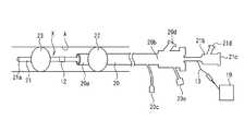
本実施形態では、図5及び図8に示すように、第1のカテーテル本体20内に第2のカテーテル本体21が遊挿されて、2つのカテーテル本体20,21が入れ子状に配置されている。Next, a second embodiment will be described with reference to the drawings. In addition, the same code | symbol is attached | subjected and demonstrated about the member similar to said each embodiment.
In this embodiment, as shown in FIGS. 5 and 8, the
第1のカテーテル本体20及び第2のカテーテル本体21の各先端部20a、21a側には、それぞれバルーン22,23が配設されている。
上記第1のカテーテル本体20には、ルーメンとして通過ルーメン24、バルーンルーメン25及び注入用ルーメン26が設けられている。
上記通過ルーメン24は、第2のカテーテル本体21を遊挿するための一番大きなルーメンであって、第1のカテーテル本体20に沿って尾端部20bから先端部20aまで延び、当該第1のカテーテル本体20の先端部20aで開口していると共に吸引用ポート20dに連通している。
The
The
また、注入用ルーメン26は、図8のように、尾端部20b側で注入用ポート20cに連通し、当該尾端部20b側から先端部20aまで延び、当該第1のカテーテル本体20の先端部20aで開口している。
さらに、バルーン用ルーメン25は、尾端部20bにあるバルーンポート20eに連通すると共に、バルーン22の位置まで延在してバルーン22の内部に連通している。Further, as shown in FIG. 8, the
Further, the
また、第2のカテーテル本体21には、図7に示すように、ガイドワイヤルーメン27及びバルーンルーメン28が設けられている。
ガイドワイヤルーメン27は、尾端部21bのガイドワイヤポート21cからガイドワイヤ8が挿入されるルーメンであって、第2のカテーテル本体21に沿って尾端部21bから先端部21aまで延び、当該第2のカテーテル本体21の先端部21aで開口している。
また、バルーンルーメン28は、尾端部21bにあるバルーンポート21dに連通すると共に、バルーン23の位置まで延在してバルーン23の内部に連通している。The
The
The
また、第2のカテーテル本体21におけるバルーン23位置よりも近位の位置に、超音波プローブ12が円環状に配置されている。この超音波プローブ12は、第2のカテーテル本体21内に埋設された電線13を介して超音波発生器19に接続され、当該超音波発生器19によって、例えば20kHz〜200MHzの範囲のうちの病変破砕に適した周波数帯の超音波を発生し外径方向に照射可能となっている。
なお、第2のカテーテル本体21に超音波プローブ12を設ける代わりに、第1のカテーテル本体20におけるバルーン22よりも遠位である先端部20a側に超音波プローブを設けても良い。In addition, the
Instead of providing the
次に、上記構成の組織破砕装置の使用例などについて説明する。
まず、ガイディングカテーテル(不図示)を、病変のある血管A内に挿入して留置する。
続いて、上記のように第1のカテーテル本体20内に第2のカテーテル本体21及びガイドワイヤ8を予め組み合わせた状態で、上記ガイディングカテーテル内を通じて、血管A内へ、血流と逆行方向に挿入して、さらに、第1のカテーテル本体20から第2のカテーテル本体21をバルーン23及び超音波プローブ12が露出するまで突き出した状態として、図5に示すように、2つのバルーン22,23の間に病変部組織40が位置するように調整する。Next, a usage example of the tissue crushing apparatus having the above configuration will be described.
First, a guiding catheter (not shown) is inserted into the lesioned blood vessel A and placed.
Subsequently, the
次に、各バルーンルーメン25,28に気体を圧送して各バルーン22,23を拡張して血管Aを局所的に閉鎖して両バルーン22,23間に閉鎖領域Xを形成する。
次に、注入ポートから注入用ルーメン26を通じて上記閉鎖領域Xに脱気された液体や界面活性剤を注入することで超音波が伝搬しやすい環境として、当該閉鎖領域Xに存在する病変を超音波にて非接触で破砕しやすくする。Next, gas is pumped to the
Next, the lesion existing in the closed region X is ultrasonicated as an environment in which ultrasonic waves are easily propagated by injecting the degassed liquid or surfactant into the closed region X through the
この状態で、超音波発生器19を作動させて上記閉鎖領域X内に存在する病変組織40を超音波にて破砕する。
その後、閉鎖領域X内の物質、特に破砕して遊離した病変組織を、上記通過ルーメン24と第2のカテーテル本体21との間の隙間を吸引用通路として使用して吸引する。
これによって、2つのバルーン22,23で閉鎖された、病変を含む局所的な部分でのみ超音波による病変の破砕が行われて、健康な組織への影響を最小限に抑えることができる。In this state, the
Thereafter, the substance in the closed region X, particularly the lesion tissue released by crushing, is sucked using the gap between the
As a result, the lesion is disrupted by the ultrasonic wave only at a local portion including the lesion which is closed by the two
また、脱気した気体を閉鎖領域Xに送ることで、超音波を非接触式であっても効果的に作用させることができる。さらに、吸引することで病変を除去することができる。
その他の構成や作用効果については上記第1実施形態と同様である。
ここで、上記説明では、注入用ルーメン26によって直接、流体の注入を行っているが、これに限定されない。例えば、図9に示すように、注入用ルーメン26内に注入用の細径の注入用チューブ29を挿入して、その注入用チューブ29を使用して注入を行うようにしても良い。この場合には、第1のカテーテル本体20の先端部から注入用チューブ29を突出させて注入することなる。Further, by sending the degassed gas to the closed region X, it is possible to effectively act even if the ultrasonic wave is a non-contact type. Furthermore, the lesion can be removed by aspiration.
Other configurations and operational effects are the same as those in the first embodiment.
Here, in the above description, the fluid is directly injected by the
次に、第3の実施形態について図面を参照しつつ説明する。なお、上記各実施形態と同様な部材などについては同一の符号を付して説明する。
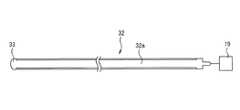
本実施形態では、図10に示すように、導管を構成するガイド用カテーテル30と、そのガイド用カテーテル30内に形成した通過用ルーメン31に挿入される線状のガイド部材32とを備える。Next, a third embodiment will be described with reference to the drawings. In addition, the same code | symbol is attached | subjected and demonstrated about the member similar to said each embodiment.
In this embodiment, as shown in FIG. 10, a
上記ガイド部材32の本体32aは、図11のように、可撓性のある素材から構成され表面が絶縁体から構成される。また、ガイド部材32の先端には超音波プローブ33が設けられている。超音波プローブ33の形状は特に限定されないが、半球状、球状、円錐台状などの形状が採用される。
そして、上記ガイド用カテーテル30を、病変のある血管A内に挿入し、その先端部が病変近傍にアプローチするまで挿入する。As shown in FIG. 11, the
The
続いて、図10のように、ガイド用カテーテル30内を通じてガイド部材32の先端部を病変組織である血栓34に接近させ、さらに、当該血栓34に超音波プローブ33を接触させる。本実施形態では、符号35は血管狭窄部を示す。
この状態で、超音波発生器19を作動させて、直接、超音波で血栓34を破砕する。
ここで、上記説明では、導管としてカテーテルを例示しているが、針であっても良い。この場合には、図12に示すように、中空の針40を病巣部内部まで突き刺し、経皮的に挿入させ、その針内を通じて上記ガイド部材32の先端部を病巣内部50に配置し、その状態で超音波を発生して、周囲の病変組織を破壊する。肝癌、乳癌などに好適な方法となる。Subsequently, as shown in FIG. 10, the distal end portion of the
In this state, the
Here, in the above description, a catheter is exemplified as the conduit, but a needle may be used. In this case, as shown in FIG. 12, a
ここで、発明者の実験によれば、特定の超音波周波数及び強度を選択すれば、超音波プローブ33に接触した膜などの物質を破壊することなく、内部の組織、例えば細胞の核だけを破砕することができることを確認している。したがって、予め実験などによって病変組織の種類と、それを破砕する周波数帯及び強度を求めておけば、選択的に特定の病変部を破砕することが可能である。 Here, according to the experiment by the inventors, if a specific ultrasonic frequency and intensity are selected, only the inner tissue, for example, the nucleus of the cell, is destroyed without destroying a substance such as a film in contact with the
また、対象とする組織としては、上述のような病変組織に限定されず、卵細胞内の細胞質を対象としても良い。予め実験にて、卵細胞中の対象とする細胞質が高速回転する周波数帯を特定しておき、その特定した周波数帯で且つ所定強度以上の超音波を上記卵細胞52に付与すれば、卵細胞中の細胞質が高速回転して当該細胞質だけを破裂させることができる。 Further, the target tissue is not limited to the above-described lesioned tissue, and the cytoplasm in the egg cell may be the target. If the frequency band in which the target cytoplasm in the egg cell rotates at high speed is specified in advance in the experiment, and the ultrasonic wave having the specified frequency band and a predetermined intensity or higher is applied to the
次に、その卵細胞中の細胞質だけを破砕する実証例を示す。
実験としては、図13に示すように、超音波源となる圧電素子50(PZT)に、基端部が直径1mmの断面円形のガラス棒51を接続する。該ガラス棒51の先端部の寸法は直径50〜60μmである。このガラス棒51の先端を卵細胞52の表皮に接触させ、該卵細胞52に超音波を伝達可能状態とする。ここで、実験に使用した卵細胞はウシ卵細胞で直径が50〜100μmのものを使用した。
そして、上記圧電素子50に周波数≒196kHzの交流を与え、電圧(超音波の強度)を徐々に上昇させていくと、卵細胞52内の細胞質が回転を始め、上記電圧が5V以上になると、上記細胞質が高速で回転し、ばらつきがあるが、電圧が8V〜10V以上で当該細胞質のみが破裂した。Next, a demonstration example in which only the cytoplasm in the egg cell is disrupted is shown.
As an experiment, as shown in FIG. 13, a glass rod 51 having a circular cross section with a base end portion having a diameter of 1 mm is connected to a piezoelectric element 50 (PZT) serving as an ultrasonic source. The size of the tip of the glass rod 51 is 50-60 μm in diameter. The tip of the glass rod 51 is brought into contact with the epidermis of the
Then, when an alternating current having a frequency ≈ 196 kHz is applied to the
また、電圧を8V未満に設定しておき、上記周波数(196kHz)を中心として、少しだけ周波数を変更(プラス又はマイナス)させてみたところ、回転する細胞質の大きさが異なっていた。すなわち、対象とする細胞質の大きさに応じて、上記周波数から所定だけ変動させることで、選択的に対象とする細胞質だけを破砕することが可能であることを確認した。
このことから、不妊処理など、卵細胞52中の核だけを選択的に破砕することが可能であることが分かる。In addition, when the voltage was set to less than 8 V and the frequency was slightly changed (plus or minus) around the frequency (196 kHz), the size of the rotating cytoplasm was different. That is, it was confirmed that only the target cytoplasm can be selectively disrupted by changing the frequency from the frequency by a predetermined amount according to the size of the target cytoplasm.
From this, it is understood that only the nucleus in the
X 閉鎖領域
A 血管
1 カテーテル本体
2、3 バルーン
4 ガイド用ルーメン
5 注入用ルーメン
6 吸引用ルーメン
7 バルーン用ルーメン
8 ガイドワイヤ
9 バイパス用開口部
10 注入口
11 吸引口
12 超音波プローブ
19 超音波発生器
20 第1のカテーテル本体
21 第2のカテーテル本体
22 バルーン(第1のバルーン)
23 バルーン(第2のバルーン)
24 通過ルーメン
25 バルーンルーメン
26 注入用ルーメン
27 ガイドワイヤルーメン
28 バルーンルーメン
29 注入用チューブ
30 ガイド用カテーテル
31 通過用ルーメン
32 ガイド部材
33 超音波プローブ
34 血栓
35 血管狭窄部
40 病変組織
50 圧電素子
52 卵細胞X closed area
A Blood vessel 1
23 Balloon (second balloon)
24
Claims (7)
Translated fromJapanese上記2つのバルーン間に位置する上記カテーテル本体の部分に、超音波を発生する超音波プローブを設けたことを特徴とする組織破砕装置。For a catheter in which a plurality of lumens extending in the axial direction are formed in one catheter body, and two balloons expandable in the outer diameter direction with respect to the catheter body are arranged side by side in the axial direction.
An apparatus for disrupting tissue, wherein an ultrasonic probe for generating an ultrasonic wave is provided in a portion of the catheter body located between the two balloons.
Priority Applications (1)
| Application Number | Priority Date | Filing Date | Title |
|---|---|---|---|
| JP2005037531AJP2006223341A (en) | 2005-02-15 | 2005-02-15 | Tissue disruption device |
Applications Claiming Priority (1)
| Application Number | Priority Date | Filing Date | Title |
|---|---|---|---|
| JP2005037531AJP2006223341A (en) | 2005-02-15 | 2005-02-15 | Tissue disruption device |
Publications (1)
| Publication Number | Publication Date |
|---|---|
| JP2006223341Atrue JP2006223341A (en) | 2006-08-31 |
Family
ID=36985229
Family Applications (1)
| Application Number | Title | Priority Date | Filing Date |
|---|---|---|---|
| JP2005037531APendingJP2006223341A (en) | 2005-02-15 | 2005-02-15 | Tissue disruption device |
Country Status (1)
| Country | Link |
|---|---|
| JP (1) | JP2006223341A (en) |
Cited By (7)
| Publication number | Priority date | Publication date | Assignee | Title |
|---|---|---|---|---|
| JP2008253304A (en)* | 2007-03-30 | 2008-10-23 | Japan Health Science Foundation | Medical guidewire |
| JP2015509395A (en)* | 2012-02-13 | 2015-03-30 | ニューロダイアミクス,エルエルシー | Catheter for use in revascularization procedures and method of using the same |
| WO2016064076A1 (en)* | 2014-10-20 | 2016-04-28 | Catholic Kwandong University Industry Foundation | Catheter assembly |
| WO2016064077A1 (en)* | 2014-10-20 | 2016-04-28 | Catholic Kwandong University Industry Foundation | Catheter assembly |
| JP2021090707A (en)* | 2019-12-07 | 2021-06-17 | 貴州医科大学 | Double-balloon injection catheter instrument for vessel thrombolytic |
| JP2022013816A (en)* | 2020-06-29 | 2022-01-18 | ニューラヴィ・リミテッド | Separation, weakening, and aspiration of intravascular plaque |
| CN115644984A (en)* | 2022-10-26 | 2023-01-31 | 上海百心安生物技术股份有限公司 | A pulse balloon dilatation catheter with conformal adherence and its application method |
Citations (3)
| Publication number | Priority date | Publication date | Assignee | Title |
|---|---|---|---|---|
| JPH0251517U (en)* | 1988-10-03 | 1990-04-11 | ||
| JP2000175933A (en)* | 1998-12-15 | 2000-06-27 | Toshiba Corp | Ultrasonic cautery treatment device |
| JP2004503324A (en)* | 2000-07-13 | 2004-02-05 | トランサージカル,インコーポレイテッド | Energy imparting device with expandable annular lens |
- 2005
- 2005-02-15JPJP2005037531Apatent/JP2006223341A/enactivePending
Patent Citations (3)
| Publication number | Priority date | Publication date | Assignee | Title |
|---|---|---|---|---|
| JPH0251517U (en)* | 1988-10-03 | 1990-04-11 | ||
| JP2000175933A (en)* | 1998-12-15 | 2000-06-27 | Toshiba Corp | Ultrasonic cautery treatment device |
| JP2004503324A (en)* | 2000-07-13 | 2004-02-05 | トランサージカル,インコーポレイテッド | Energy imparting device with expandable annular lens |
Cited By (10)
| Publication number | Priority date | Publication date | Assignee | Title |
|---|---|---|---|---|
| JP2008253304A (en)* | 2007-03-30 | 2008-10-23 | Japan Health Science Foundation | Medical guidewire |
| JP2015509395A (en)* | 2012-02-13 | 2015-03-30 | ニューロダイアミクス,エルエルシー | Catheter for use in revascularization procedures and method of using the same |
| WO2016064076A1 (en)* | 2014-10-20 | 2016-04-28 | Catholic Kwandong University Industry Foundation | Catheter assembly |
| KR20160046214A (en)* | 2014-10-20 | 2016-04-28 | 가톨릭관동대학교산학협력단 | Catheter assembly |
| WO2016064077A1 (en)* | 2014-10-20 | 2016-04-28 | Catholic Kwandong University Industry Foundation | Catheter assembly |
| KR101722508B1 (en)* | 2014-10-20 | 2017-04-03 | 가톨릭관동대학교산학협력단 | Catheter assembly |
| JP2021090707A (en)* | 2019-12-07 | 2021-06-17 | 貴州医科大学 | Double-balloon injection catheter instrument for vessel thrombolytic |
| JP2022013816A (en)* | 2020-06-29 | 2022-01-18 | ニューラヴィ・リミテッド | Separation, weakening, and aspiration of intravascular plaque |
| CN115644984A (en)* | 2022-10-26 | 2023-01-31 | 上海百心安生物技术股份有限公司 | A pulse balloon dilatation catheter with conformal adherence and its application method |
| CN115644984B (en)* | 2022-10-26 | 2025-03-18 | 上海百心安生物技术股份有限公司 | A conformable and wall-adherent pulse balloon dilatation catheter and its use method |
Similar Documents
| Publication | Publication Date | Title |
|---|---|---|
| US11564729B2 (en) | Torus balloon with energy emitters for intravascular lithotripsy | |
| EP2496165B1 (en) | Lumenal remodelling device | |
| CN102917748B (en) | Intravascular tissue disruption | |
| JP6018155B2 (en) | Method and system for performing submucosal medical procedures | |
| US10456563B2 (en) | Steerable, conformable, drug eluting balloon catheter | |
| JP5636363B2 (en) | Shock wave balloon catheter device | |
| CN114746032A (en) | Small Electrodes for Shockwave Guides | |
| US20140107481A1 (en) | Delivery and administration of compositions using interventional catheters | |
| US20150265343A1 (en) | Anatomical structure access and penetration | |
| EP3946087B1 (en) | Excisional devices | |
| US20130261544A1 (en) | Device for a biological treatment | |
| JPH02503161A (en) | Expandable pullback acerectomy catheter system | |
| US20200261693A1 (en) | Bypass catheter | |
| US20100286705A1 (en) | Vascular access to extra-vascular space | |
| JPH01288249A (en) | Apparatus and method for treating patient having blood vessel clogged with precipitate | |
| JP2024503651A (en) | combination balloon catheter | |
| CN115192122A (en) | Shockwave Balloon Catheter Device | |
| JP2006223341A (en) | Tissue disruption device | |
| EP4146322A1 (en) | Torus balloon with energy emitters for intravascular lithotripsy | |
| JP2004506454A (en) | Percutaneous and remote endarterectomy method and apparatus | |
| EP2785288B1 (en) | A lesion treatment device | |
| WO2024220116A1 (en) | Intravascular lithotripsy catheter with slotted emitter bands | |
| US20220331555A1 (en) | Intravascular devices and methods for delivery of fluids and therapeutic agents into blood vessel walls and intravascular structures | |
| CN117159889B (en) | Medicine saccule catheter | |
| US20250176992A1 (en) | Magnetic milli-spinner for untethered robotic endovascular surgery and methods for use |
Legal Events
| Date | Code | Title | Description |
|---|---|---|---|
| A621 | Written request for application examination | Free format text:JAPANESE INTERMEDIATE CODE: A621 Effective date:20080214 | |
| A977 | Report on retrieval | Free format text:JAPANESE INTERMEDIATE CODE: A971007 Effective date:20090807 | |
| A131 | Notification of reasons for refusal | Free format text:JAPANESE INTERMEDIATE CODE: A131 Effective date:20090818 | |
| A521 | Written amendment | Free format text:JAPANESE INTERMEDIATE CODE: A523 Effective date:20090928 | |
| A131 | Notification of reasons for refusal | Free format text:JAPANESE INTERMEDIATE CODE: A131 Effective date:20091110 | |
| A02 | Decision of refusal | Free format text:JAPANESE INTERMEDIATE CODE: A02 Effective date:20100309 |