Movatterモバイル変換


[0]ホーム

URL:


JP2006221665A - Information processor - Google Patents

Information processor
Download PDF

Info

Publication number
JP2006221665A
JP2006221665AJP2006088489AJP2006088489AJP2006221665AJP 2006221665 AJP2006221665 AJP 2006221665AJP 2006088489 AJP2006088489 AJP 2006088489AJP 2006088489 AJP2006088489 AJP 2006088489AJP 2006221665 AJP2006221665 AJP 2006221665A
Authority
JP
Japan
Prior art keywords
button
cpu
operated
lcd
touch pad
Prior art date
Legal status (The legal status is an assumption and is not a legal conclusion. Google has not performed a legal analysis and makes no representation as to the accuracy of the status listed.)
Pending
Application number
JP2006088489A
Other languages
Japanese (ja)
Inventor
Shigemi Yamada
滋実 山田
Ryoji Amamiya
亮治 雨宮
Tatsuya Isoda
達哉 磯田
Current Assignee (The listed assignees may be inaccurate. Google has not performed a legal analysis and makes no representation or warranty as to the accuracy of the list.)
Sony Corp
Original Assignee
Sony Corp
Priority date (The priority date is an assumption and is not a legal conclusion. Google has not performed a legal analysis and makes no representation as to the accuracy of the date listed.)
Filing date
Publication date
Application filed by Sony CorpfiledCriticalSony Corp
Priority to JP2006088489ApriorityCriticalpatent/JP2006221665A/en
Publication of JP2006221665ApublicationCriticalpatent/JP2006221665A/en
Pendinglegal-statusCriticalCurrent

Links

Images

Landscapes

Abstract

<P>PROBLEM TO BE SOLVED: To input various kinds of information without increasing the scale of an information processor. <P>SOLUTION: An LCD is disposed on the back of a touch pad 11 for a portable personal computer 1, and when a function button 14 for a portable personal computer 1 is operated by a user, a menu for selection of a function is displayed on the LCD. When the user operates the touch pad 11 to select, for example, ten keys from the menu configured of the ten keys, a game, a clock, a pen, a note, a telephone book, an address book, a calendar, a schedule, a wall paper, an electronic calculator, function setting, etc., ten keys are displayed on the LCD. Desired operation can be performed by operating the ten keys through a touch pad 11. <P>COPYRIGHT: (C)2006,JPO&NCIPI

Description

Translated fromJapanese

本発明は、情報処理装置に関し、特に、装置を大型化することなく、簡単かつ確実に、多くの入力を行うことができるようにした情報処理装置に関する。  The present invention relates to an information processing apparatus, and more particularly, to an information processing apparatus capable of performing many inputs easily and reliably without increasing the size of the apparatus.

最近、携帯型パーソナルコンピュータが普及しつつある。この携帯型パーソナルコンピュータが普及する理由の1つに、例えば、ユーザが、同一の建物内において、他の部屋に出かけていったり、あるいは、得意先に出向いて各種の情報をプレゼンテーションしたりするのが比較的簡単にでき、利便性が高いことがあげられる。従って、当然のことながら、携帯型パーソナルコンピュータは、小型で軽量であることが、その本来の機能から要求される。  Recently, portable personal computers are becoming popular. One of the reasons for the popularity of portable personal computers is that, for example, a user goes to another room in the same building, or goes to a customer to present various information. Can be made relatively simple and is highly convenient. Therefore, as a matter of course, a portable personal computer is required to be small and lightweight because of its original function.

また、多くのユーザが、簡単に操作できるようにするために、マウスに代表される、ポインティングデバイスが、コンピュータの入力装置として利用されるようになってきた。ポインティングデバイスを用いれば、キーボードに不慣れなものでも、比較的簡単に入力を行うことができるので、ポインティングデバイスは、近年、急速に普及しつつある。特に、携帯型パーソナルコンピュータの場合、マウスを本体とは別に所持するのは不便であるところから、タッチパッド、トラックボールといった、ポインティングデバイスが設けられていることが多い。  In order to allow many users to operate easily, a pointing device represented by a mouse has been used as an input device of a computer. If a pointing device is used, even a user who is unfamiliar with a keyboard can input relatively easily, and the pointing device has been rapidly spreading in recent years. In particular, in the case of a portable personal computer, since it is inconvenient to carry a mouse separately from the main body, a pointing device such as a touchpad or a trackball is often provided.

ところで、例えば、特開平10−214154号公報には、ポインティングデバイスを携帯型パーソナルコンピュータに対して着脱自在とし、ポインティングデバイスをリモートコントローラとして利用することができるようにし、利便性を図ることが提案されている。  By the way, for example, Japanese Patent Laid-Open No. 10-214154 proposes to make the pointing device detachable from the portable personal computer so that the pointing device can be used as a remote controller for convenience. ing.

また、特開平10−74119号公報には、携帯型パーソナルコンピュータに対して、PDA(Personal Digital Assistant)を着脱自在とし、PDAをプレゼンテーションにおいて遠隔操作に用いることができるようにするだけでなく、スタンドアローンとしても利用できるようにすることで、より利便性を高めるようにすることが提案されている。  Japanese Patent Application Laid-Open No. 10-74119 discloses not only a PDA (Personal Digital Assistant) that can be attached to and detached from a portable personal computer so that the PDA can be used for remote operation in a presentation. It has been proposed to improve convenience by making it available as a standalone.

しかしながら、先に提案されているようなポインティングデバイスは、いずれも、場合に応じて、多くの種類の入力の中から所定のものを選択的に入力することができるようにするには、ボタンやスイッチなどが多く必要となり、大型化してしまう課題あった。その結果、それを装着する携帯型パーソナルコンピュータも大型化してしまい、結局、その利用範囲は限られたものにならざるを得ない課題があった。  However, any of the pointing devices as proposed previously can be used to selectively input a predetermined one of many types of inputs depending on the situation. A large number of switches and the like were required, and there was a problem of increasing the size. As a result, the portable personal computer to which it is attached is also increased in size, resulting in a problem that the range of use must be limited.

さらに提案されているPDAは、ポインティングデバイスとしての機能を有していないので、ポインティングデバイスとして、マウスなどをさらに付加しなければならず、装置が大型化し、コスト高となる課題があった。  Further, since the proposed PDA does not have a function as a pointing device, a mouse or the like has to be further added as a pointing device, and there is a problem that the apparatus becomes large and the cost is high.

本発明はこのような状況に鑑みてなされたものであり、装置を大型化することなく、多くの情報を簡単に、かつ、ポインティングデバイスとして入力することができるようにするものである。  The present invention has been made in view of such a situation, and allows a large amount of information to be easily input as a pointing device without increasing the size of the apparatus.

本発明の一側面は、所定の入力を行う第1の入力手段と、前記第1の入力手段によって入力された情報を処理する処理手段と、前記処理手段によって処理された情報を表示する第1の表示手段と、前記処理手段によって処理された情報を表示する第2の表示手段とを備える情報処理装置である。  One aspect of the present invention is a first input means for performing a predetermined input, a processing means for processing information input by the first input means, and a first for displaying information processed by the processing means. Information processing apparatus, and a second display means for displaying information processed by the processing means.

本発明の一側面においては、所定の入力を行われ、入力された情報が処理され、処理された情報が第1の表示手段と第2の表示手段に表示される。  In one aspect of the present invention, predetermined input is performed, the input information is processed, and the processed information is displayed on the first display unit and the second display unit.

以上のように、本発明の一側面によれば、装置を大型化することなく、多くの情報を簡単に、かつ、ポインティングデバイスとして入力することができる。  As described above, according to one aspect of the present invention, a large amount of information can be easily input as a pointing device without increasing the size of the apparatus.

以下、本発明を適用したノート型の携帯型パーソナルコンピュータについて添付図面に基づいて詳細に説明する。  A notebook portable personal computer to which the present invention is applied will be described in detail below with reference to the accompanying drawings.

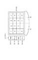
図1に示すように、携帯型パーソナルコンピュー1の本体2には、文字等を入力するとき操作されるキーボード4が設けられている。画像を表示する表示部3は、本体2に対して開閉(折り畳み)自在に取り付けられている。また、図においては示していないが、本体2に対しては、外部のポインティングデバイスとしてマウス等を外付けすることもできる。  As shown in FIG. 1, themain body 2 of the portablepersonal computer 1 is provided with akeyboard 4 that is operated when inputting characters or the like. Thedisplay unit 3 for displaying an image is attached to themain body 2 so as to be freely opened and closed (folded). Although not shown in the drawing, a mouse or the like can be externally attached to themain body 2 as an external pointing device.

本体2は電源ランプPL、電池ランプBL、そしてメッセージランプMLを有し、電源ランプPLは電源オン時に点灯し、電池ランプBLはバッテリパック5の電池残量の程度を示す。これらのランプの内の特にメッセージランプMLは、表示部3を本体2に対して閉じた状態でも外部に表出している。これにより表示部3を閉じていても所定のプログラムの動作は、メッセージランプMLの点灯により利用者に報知することができる。  Themain body 2 includes a power lamp PL, a battery lamp BL, and a message lamp ML. The power lamp PL is lit when the power is turned on, and the battery lamp BL indicates the degree of remaining battery capacity of thebattery pack 5. Among these lamps, in particular, the message lamp ML is exposed to the outside even when thedisplay unit 3 is closed with respect to themain body 2. Thus, even when thedisplay unit 3 is closed, the operation of the predetermined program can be notified to the user by turning on the message lamp ML.

本体2の側面には、電源をオンまたはオフするとき操作される電源スイッチ6と、ワンタッチ操作用の操作キー7が設けられている。この操作キー7は、所定のアプリケーションを瞬時に立ち上げるとき操作され、その立上げ状態がメッセージランプMLにより表示される。さらに本体2の側面には、PCMCIA(Personal Computer Memory Card International Association)カード(いわゆるPCカード)が装着されるスロット8が設けられている。  On the side surface of themain body 2, apower switch 6 that is operated when the power is turned on or off and anoperation key 7 for one-touch operation are provided. Theoperation key 7 is operated when a predetermined application is started up instantaneously, and the start-up state is displayed by the message lamp ML. Further, aslot 8 in which a PCMCIA (Personal Computer Memory Card International Association) card (so-called PC card) is mounted is provided on the side surface of themain body 2.

本体2の上面のキーボード4の手前には、タッチ操作部9が設けられている。このタッチ操作部9は、タッチパッド11、左ボタン12、右ボタン13、および機能ボタン14により構成されている。  Atouch operation unit 9 is provided in front of thekeyboard 4 on the upper surface of themain body 2. Thetouch operation unit 9 includes atouch pad 11, aleft button 12, aright button 13, and afunction button 14.

タッチパッド11は、ユーザにより、指またはペン(図示はしないが、表示部3の左側面に収容されている)で操作される。タッチパッド1は、例えば、表示部3のLCD41(図2)に表示されているポインタを所定の位置に移動させるとき、こするようにして操作される。左ボタン12は、「OK]や「キャンセル」などを選択したり、メニューを選ぶときなどに操作される。タッチパッド11が、指で1回軽く叩かれた場合にも、同様の機能が実行される。左ボタン12は、ダブルクリックするとき、2回続けて操作される。ポインタをドラッグする場合には、左ボタン12を操作したまま、タッチパッド11上でも指が移動される。タッチパッド11上で2回続けて軽く叩いた後、そのままタッチパッド11上で指を動かした場合も、ドラッグの操作となる。右ボタン13は、さまざまな内容のバックアップメニューを表示するときなどに操作される。  Thetouch pad 11 is operated by a user with a finger or a pen (not shown, but housed on the left side surface of the display unit 3). Thetouch pad 1 is operated in such a manner as to move the pointer displayed on the LCD 41 (FIG. 2) of thedisplay unit 3 to a predetermined position, for example. Theleft button 12 is operated when selecting “OK” or “Cancel” or selecting a menu. A similar function is performed when thetouch pad 11 is tapped once with a finger. Theleft button 12 is operated twice continuously when double-clicked. When dragging the pointer, the finger is also moved on thetouch pad 11 while operating theleft button 12. When the finger is moved on thetouch pad 11 as it is after tapping twice on thetouch pad 11, the operation is also a drag operation. Theright button 13 is operated when displaying a backup menu having various contents.

バッテリパック5の左側には、マイクロホン15が設けられており、本体2の底面の電源ランプPLの近傍にはスピーカ16が設けられている。  Amicrophone 15 is provided on the left side of thebattery pack 5, and aspeaker 16 is provided in the vicinity of the power lamp PL on the bottom surface of themain body 2.

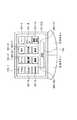
図2は、携帯型パーソナルコンピュータ1の内部の構成例を表している。本体2は、情報の処理を集中して行うCPU(Central Processing Unit)52と、揮発性のメモリであるRAM(Random Access Memory)53とを有している。これらCPU52、およびRAM53は、内部バス(PCI(Peripheral Component Interconnect) BUS)50にそれぞれ接続されている。この内部バス50には、スロット8から挿入された、所定の機能を備えたPCカード82も、インタフェース(I/F)51を介して接続される。  FIG. 2 illustrates an internal configuration example of the portablepersonal computer 1. Themain body 2 includes a CPU (Central Processing Unit) 52 that centrally processes information and a RAM (Random Access Memory) 53 that is a volatile memory. TheCPU 52 and theRAM 53 are connected to an internal bus (PCI (Peripheral Component Interconnect) BUS) 50, respectively. APC card 82 having a predetermined function inserted from theslot 8 is also connected to the internal bus 50 via an interface (I / F) 51.

CPU52は、各機能を統括するコントローラであり、PCカード82は、内部バス50に対してオプションの機能を付加するためのものである。RAM53の中には、本体2の起動が完了した時点において、アプリケーション・プログラム、オートパイロットプログラム、そして基本プログラム(operating system: OS)等が記憶される。  TheCPU 52 is a controller that controls each function, and thePC card 82 is for adding an optional function to the internal bus 50. TheRAM 53 stores an application program, an autopilot program, a basic program (operating system: OS), and the like when the activation of themain body 2 is completed.

オートパイロットプログラムは、予め設定された複数の処理(またはプログラム)等を、予め設定された順序で順次起動して、処理するプログラムである。OSは、携帯型パーソナルコンピュータ1の基本的な動作を制御するものであり、例えばWindows(登録商標)98などの、市販のマルチタスクOSを用いることができる。  The autopilot program is a program for sequentially starting and processing a plurality of preset processes (or programs) in a preset order. The OS controls basic operations of the portablepersonal computer 1, and a commercially available multitask OS such as Windows (registered trademark) 98 can be used.

また、本体2は、データの入出力を制御する入出力(in-out:I/O)コントローラ63、情報を記録する記録部であるHDD(Hard Disc Drive)55、実時間時計(real time clock: RTC)62、およびバックアップ用のバッテリ76を有している。  Themain body 2 also includes an input / output (in-out: I / O)controller 63 that controls data input / output, an HDD (Hard Disc Drive) 55 that is a recording unit for recording information, a real time clock (real time clock). : RTC) 62 and abattery 76 for backup.

I/Oコントローラ63、HDD55、RTC62、メッセージランプML、バッテリランプBL、電源ランプPL、電源スイッチ6、操作キー7、バックアップ用バッテリ76は、外部バス(ISA BUS)54にそれぞれ接続されている。外部バス54は、内部バス50に接続されている。  The I /O controller 63,HDD 55,RTC 62, message lamp ML, battery lamp BL, power lamp PL,power switch 6,operation key 7, andbackup battery 76 are connected to an external bus (ISA BUS) 54, respectively. The external bus 54 is connected to the internal bus 50.

I/Oコントローラ63は、マイクロコントローラ64を有し、このマイクロコントローラ64はCPU66、RAM67、ROM65が相互に接続されて構成されている。このRAM67は、キー入力ステイタスレジスタ72、LED制御レジスタ73、設定時刻レジスタ74、操作キー/プログラム対応関係レジスタ75を有している。設定時刻レジスタ74は、起動条件格納部であり、ユーザが予め設定した時刻(起動条件)を記憶する。これは、予め設定された時刻になると所定のプログラムを起動する一連の処理である起動シーケンスの動作を開始させる際に利用される。操作キー/プログラム対応関係レジスタ75は、予め設定された操作キーの組合せ(起動条件)と、起動すべきアプリケーションプログラムの対応を記憶するもので、予め設定された操作キーの組合せがユーザにより押されると、起動しようとするアプリケーション・プログラムが起動される。  The I /O controller 63 includes amicrocontroller 64, and themicrocontroller 64 is configured by connecting aCPU 66, aRAM 67, and aROM 65 to each other. TheRAM 67 includes a keyinput status register 72, anLED control register 73, aset time register 74, and an operation key / program correspondence register 75. Theset time register 74 is a start condition storage unit and stores a time (start condition) preset by the user. This is used when starting an operation of an activation sequence which is a series of processes for activating a predetermined program at a preset time. The operation key / program correspondence register 75 stores a preset operation key combination (startup condition) and a correspondence between the application program to be started, and the user presses the preset operation key combination. Then, the application program to be started is started.

キー入力ステイタスレジスタ72は、ワンタッチ操作用のスイッチとしての操作キー7が押されると、操作キーフラグが格納されるようになっている。LED制御レジスタ73は、操作キー7が押されて、所定のアプリケーションの瞬時の立ち上げ状態を表示するメッセージランプMLの点灯を制御するものである。設定時刻レジスタ74は、ある時刻を任意に設定することができるものである。  The key input status register 72 stores an operation key flag when theoperation key 7 as a one-touch operation switch is pressed. The LED control register 73 controls lighting of the message lamp ML that displays an instantaneous start-up state of a predetermined application when theoperation key 7 is pressed. Theset time register 74 can arbitrarily set a certain time.

なお、このマイクロコントローラ64にはバックアップ用のバッテリ76が設けられており、各レジスタ72,73,74の値は、本体2の電源がオフとされている状態においても保持されるようになっている。  Themicrocontroller 64 is provided with abackup battery 76, and the values of theregisters 72, 73, 74 are held even when the power of themain body 2 is turned off. Yes.

マイクロコントローラ64内のROM65の中には、ウェイクアッププログラム69、キー入力監視プログラム70、およびLED制御プログラム71が予め格納されている。このROM65は、例えばフラッシュメモリとも呼ばれる電気消去可能プログラマブル読出し専用メモリ(electrically erasable programmable read-only memory:EEPROM)で構成されている。さらにマイクロコントローラ64には、常時現在時刻をカウントするRTC62が接続されている。  In theROM 65 in themicrocontroller 64, a wake-upprogram 69, a keyinput monitoring program 70, and anLED control program 71 are stored in advance. TheROM 65 is composed of, for example, an electrically erasable programmable read-only memory (EEPROM) also called a flash memory. Further, anRTC 62 that always counts the current time is connected to themicrocontroller 64.

ROM65の中のウェイクアッププログラム69は、RTC62から供給される現在時刻データに基づいて、設定時刻レジスタ74に予め設定された時刻になったかどうかをチェックして、設定された時刻になると、所定の処理(又はプログラム)等を起動するプログラムである。キー入力監視プログラム70は、操作キー7が利用者により押されたかどうかを常時監視するプログラムである。LED制御プログラム71は、メッセージランプMLの点灯を制御するプログラムである。  Thewakeup program 69 in theROM 65 checks whether or not the time preset in the settime register 74 is reached based on the current time data supplied from theRTC 62. It is a program that activates a process (or program) or the like. The keyinput monitoring program 70 is a program that constantly monitors whether or not theoperation key 7 has been pressed by the user. TheLED control program 71 is a program for controlling lighting of the message lamp ML.

ROM65には、さらに、基本入出力システムとしてのBIOS(basic input/output system )68が書き込まれている。このBIOSは、OSやアプリケーションプログラムと、LCD41,57、キーボード4、HDD55等の周辺機器の間でのデータの受け渡し(入出力)を制御するソフトウェアプログラムである。  In addition, a BIOS (basic input / output system) 68 as a basic input / output system is written in theROM 65. This BIOS is a software program that controls data transfer (input / output) between the OS and application programs and peripheral devices such as theLCDs 41 and 57, thekeyboard 4, and theHDD 55.

HDD55には、アプリケーションプログラム、オートパイロットプログラム、OS等が記憶されている。HDD55内のOS、オートパイロットプログラムおよびアプリケーションプログラムは、本体2のブートアップ(boot up:起動)処理の過程で、RAM53内に順次格納される。  TheHDD 55 stores an application program, an autopilot program, an OS, and the like. The OS, the autopilot program, and the application program in theHDD 55 are sequentially stored in theRAM 53 during the boot-up process of themain body 2.

さらに、本体2は、表示部3のLCD41を制御するLCDコントローラ77、外部ネットワーク81と接続するためにデータを変換するモデム78、キーボード4を制御するキーボードコントローラ61、タッチパッド11を制御するタッチパッドコントローラ59、並びに、マイクロホン15およびスピーカ16に接続して信号を変換するインターフェース60を有している。これらLCDコントローラ77、モデム78、キーボードコントローラ61、タッチパッドコントローラ59、およびインターフェース60は、上記外部バス54にそれぞれ接続されている。  Further, themain body 2 includes anLCD controller 77 that controls theLCD 41 of thedisplay unit 3, amodem 78 that converts data for connection to theexternal network 81, akeyboard controller 61 that controls thekeyboard 4, and a touchpad that controls thetouchpad 11. Thecontroller 59 has aninterface 60 that is connected to themicrophone 15 and thespeaker 16 to convert signals. TheLCD controller 77,modem 78,keyboard controller 61,touch pad controller 59, andinterface 60 are connected to the external bus 54, respectively.

外部バス54にはまた、LCDコントローラ56が接続されている。LCDコントローラ56は、LCD57とバックライト58を制御する。LCD57は、透明な(LCD57の光を透過する)素材よりなるタッチパッド11の後方に配置されている。バックライト58は、LCD57の後方に配置され、LCD57を照明する。  AnLCD controller 56 is also connected to the external bus 54. TheLCD controller 56 controls theLCD 57 and thebacklight 58. TheLCD 57 is disposed behind thetouch pad 11 made of a transparent material (that transmits the light of the LCD 57). Thebacklight 58 is disposed behind theLCD 57 and illuminates theLCD 57.

外部バス54に接続されているキーボードコントローラ61は、キーボード4からの入力をコントロールする。タッチパッドコントローラ59は、タッチパッド11、左ボタン12、右ボタン13、および、機能ボタン14からの入力を制御する。  Akeyboard controller 61 connected to the external bus 54 controls input from thekeyboard 4. Thetouch pad controller 59 controls input from thetouch pad 11, theleft button 12, theright button 13, and thefunction button 14.

インターフェース60は、内部マイクロホン15からの入力を取り込み、あるいは内蔵スピーカ16に対して音声信号を供給する。  Theinterface 60 takes in an input from theinternal microphone 15 or supplies an audio signal to the built-inspeaker 16.

モデム78は、本体2と外部のネットワーク81とを接続して、通信を行うために情報信号のフォーマットを変換する処理を行う。  Themodem 78 connects themain body 2 and theexternal network 81 and performs processing for converting the format of the information signal in order to perform communication.

LCDコントローラ77は、表示部3のLCD41と、その後方に配置されているバックライト42とを制御する。  TheLCD controller 77 controls theLCD 41 of thedisplay unit 3 and thebacklight 42 arranged behind theLCD 41.

タッチパッド11は、キーボード4の手前側に配設され、LCD41の画面上の位置を特定するポインティングデバイスとして用いることにより、ポイントの軌跡の入力を行うものである。すなわち、ポインティングデバイスは、LCD41の表示画面に表示され、入力操作に応じて移動される指標(ポインタ)について、その指標の移動軌跡を入力するのに用いられる。また、タッチパッド11には、点の位置のみならず押圧された強さをも同時に検出することができる感圧式のタッチパッドも利用することができる。なお、本実施の形態においては、ポインティングデバイスとして、タッチパッドに限定されず、例えばタブレットを用いることもできる。  Thetouch pad 11 is disposed on the front side of thekeyboard 4 and is used as a pointing device for specifying a position on the screen of theLCD 41 to input a locus of points. That is, the pointing device is used to input a movement locus of an index (pointer) displayed on the display screen of theLCD 41 and moved in accordance with an input operation. Further, as thetouch pad 11, a pressure-sensitive touch pad that can simultaneously detect not only the position of the point but also the pressed strength can be used. In the present embodiment, the pointing device is not limited to the touch pad, and for example, a tablet can be used.

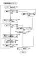
次に、図3のフローチャートを参照して、タッチ操作部9を操作した場合の動作について説明する。ステップS1において、CPU52は、機能ボタン14がユーザにより操作された(オンされた)か否かを判定する。すなわち、タッチパッドコントローラ59は、機能ボタン14がユーザにより操作されたとき、その操作信号を外部バス54と内部バス50を介してCPU52に出力する。CPU52は、ステップS1において、機能ボタン14が操作されたと判定された場合、拡張モードを設定するとともに、ステップS6に進み、機能選択処理を実行する。この機能選択処理の詳細は、図4のフローチャートを参照して後述する。  Next, the operation when thetouch operation unit 9 is operated will be described with reference to the flowchart of FIG. In step S1, theCPU 52 determines whether or not thefunction button 14 has been operated (turned on) by the user. That is, when thefunction button 14 is operated by the user, thetouch pad controller 59 outputs the operation signal to theCPU 52 via the external bus 54 and the internal bus 50. If it is determined in step S1 that thefunction button 14 has been operated, theCPU 52 sets an expansion mode and proceeds to step S6 to execute a function selection process. Details of this function selection processing will be described later with reference to the flowchart of FIG.

ステップS1において、機能ボタン14が操作されていないと判定された場合、CPU52により通常動作モードが設定されており、CPU52は、ステップS2において、タッチパッド11がユーザにより操作されたか否かを判定する。すなわち、タッチパッドコントローラ59は、タッチパッド11がユーザにより操作されたとき、その座標データを検出し、これをCPU52に出力する。CPU52は、ステップS2において、タッチパッド11が操作されたと判定された場合(タッチパッドコントローラ59より座標データが供給されてきたとき)、ステップS7に進み、入力された座標データに対応する処理を実行する。  When it is determined in step S1 that thefunction button 14 is not operated, the normal operation mode is set by theCPU 52, and theCPU 52 determines whether or not thetouch pad 11 is operated by the user in step S2. . That is, when thetouch pad 11 is operated by the user, thetouch pad controller 59 detects the coordinate data and outputs the detected coordinate data to theCPU 52. When it is determined in step S2 that thetouch pad 11 has been operated (when coordinate data is supplied from the touch pad controller 59), theCPU 52 proceeds to step S7 and executes processing corresponding to the input coordinate data. To do.

例えば、いま、LCDコントローラ77により、表示部3のバックライト42とLCD41が駆動され、バックライト42により照明されているLCD41に所定の画像が表示されている状態において、ユーザが、タッチパッド11の右端を上下方向になぞったとき、表示されている画像を上下方向に移動(スクロール)させる。タッチパッド11の下端が左右方向にこすられたとき、CPU52は、LCD41に表示されている画像を左右方向に移動(スクロール)させる。ユーザがタッチパッド11を操作したとき、CPU52がどのような処理を行うかは、CPU52が、そのとき実行しているアプリケーションプログラムによって決定される。  For example, when thebacklight 42 and theLCD 41 of thedisplay unit 3 are driven by theLCD controller 77 and a predetermined image is displayed on theLCD 41 illuminated by thebacklight 42, the user can When the right end is traced in the vertical direction, the displayed image is moved (scrolled) in the vertical direction. When the lower end of thetouch pad 11 is rubbed in the left-right direction, theCPU 52 moves (scrolls) the image displayed on theLCD 41 in the left-right direction. What processing theCPU 52 performs when the user operates thetouch pad 11 is determined by the application program being executed by theCPU 52 at that time.

ステップS2において、タッチパッド11から入力がないと判定された場合、ステップS3に進み、CPU52は、左ボタン12または右ボタン13がユーザにより操作されたか否かを判定する。タッチパッドコントローラ59は、左ボタン12または右ボタン13がユーザにより操作されたとき、その操作信号をCPU52に出力する。CPU5266は、操作信号の入力を受けたとき、ステップS8において、そのとき実行しているアプリケーションプログラムに基づいて、その意味を解釈し、マウスの左ボタンまたは右ボタンが操作された場合と同様の処理を実行する。  If it is determined in step S2 that there is no input from thetouch pad 11, the process proceeds to step S3, and theCPU 52 determines whether theleft button 12 or theright button 13 is operated by the user. Thetouch pad controller 59 outputs an operation signal to theCPU 52 when theleft button 12 or theright button 13 is operated by the user. When the CPU 5266 receives an input of an operation signal, in step S8, the CPU 5266 interprets the meaning based on the application program being executed at that time, and performs the same processing as when the left or right mouse button is operated. Execute.

ステップS3において、左ボタン12または右ボタン13が操作されていないと判定された場合、ステップS4に進み、LCDコントローラ56は、CPU52から表示すべき画像データの供給を受けているか否かを判定する。表示すべき画像データを受信したとき、ステップS5に進み、LCDコントローラ56は、CPU52より供給された画像データをLCD57に出力し、表示させる。もちろん、このとき、LCDコントローラ56は、バックライト58を点灯し、LCD57を後方から照明する。LCD57の上面には、タッチパッド11が配置されているが、タッチパッド11は、透明の素材で形成されているため、ユーザは、タッチパッド11を介して、その下方(背面)に配置されているLCD57に表示されている画像を視認することができる。  If it is determined in step S3 that theleft button 12 or theright button 13 is not operated, the process proceeds to step S4, and theLCD controller 56 determines whether image data to be displayed is received from theCPU 52 or not. . When the image data to be displayed is received, the process proceeds to step S5, where theLCD controller 56 outputs the image data supplied from theCPU 52 to theLCD 57 for display. Of course, at this time, theLCD controller 56 lights thebacklight 58 and illuminates theLCD 57 from behind. Thetouch pad 11 is disposed on the upper surface of theLCD 57. However, since thetouch pad 11 is formed of a transparent material, the user is disposed below (rear surface) through thetouch pad 11. The image displayed on theLCD 57 can be visually recognized.

ステップS4において、CPU52から表示すべき画像データが供給されてきていないと判定された場合、また、ステップS5のデータ表示処理が終了したとき、ステップS1に戻り、それ以降の処理が繰り返し実行される。  If it is determined in step S4 that image data to be displayed has not been supplied from theCPU 52, or if the data display process in step S5 is completed, the process returns to step S1, and the subsequent processes are repeatedly executed. .

このように、機能ボタン14がオンされていない場合には、ユーザは、タッチパッド11を介して、従来の場合と同様の入力を行うことができる。例えば、CPU52が、所定のアプリケーションを起動している最中に、ユーザが図示せぬペンでタッチパッド11を操作したとき、その座標データが、ステップS7でCPU52に供給される。このときCPU52は、入力に対応する座標データをLCDコントローラ77に出力し、LCD41にペンで描かれた軌跡を表示させる。  As described above, when thefunction button 14 is not turned on, the user can perform the same input as in the conventional case via thetouch pad 11. For example, when the user operates thetouchpad 11 with a pen (not shown) while theCPU 52 is starting a predetermined application, the coordinate data is supplied to theCPU 52 in step S7. At this time, theCPU 52 outputs coordinate data corresponding to the input to theLCD controller 77 and causes theLCD 41 to display a locus drawn with a pen.

CPU52が、そのように制御した場合には、LCD41に表示された軌跡が、表示すべきデータとしてLCDコントローラ56に供給される。このとき、LCDコントローラ56は、入力された画像データをLCD57に出力し、表示させる。これにより、LCD41に表示された軌跡と同一の軌跡がLCD57にも表示される。  When theCPU 52 performs such control, the locus displayed on theLCD 41 is supplied to theLCD controller 56 as data to be displayed. At this time, theLCD controller 56 outputs the input image data to theLCD 57 for display. As a result, the same trajectory displayed on theLCD 41 is also displayed on theLCD 57.

次に、図4のフローチャートを参照して、図3のステップS6における機能選択処理の詳細について説明する。この処理は、上述したように、ユーザが機能ボタンを14を操作(オン)したとき開始される。  Next, details of the function selection process in step S6 of FIG. 3 will be described with reference to the flowchart of FIG. This process is started when the user operates (turns on) thefunction button 14 as described above.

CPU25は、ステップS11において、各種の機能をユーザに選択させるためのメニュー画面をLCDコントローラ56を介してLCD57に表示させる。図5は、このようなメニュー画面の表示例を表している。この表示例においては、テンキーボタン101−1、ゲームボタン101−2、時計ボタン101−3、ペンボタン101−4、メモボタン101−5、電話帳ボタン101−6、住所録ボタン101−7、カレンダーボタン101−8、スケジュールボタン101−9、壁紙ボタン101−10、電卓ボタン101−11、および機能設定ボタン101−12などの各種の機能を選択するための選択ボタンが表示されているとともに、いずれかの選択ボタンを選択したとき、その選択を確定(決定)するとき操作される決定ボタン112が表示されている。  In step S <b> 11, the CPU 25 displays a menu screen for allowing the user to select various functions on theLCD 57 via theLCD controller 56. FIG. 5 shows a display example of such a menu screen. In this display example, a numeric keypad button 101-1, a game button 101-2, a clock button 101-3, a pen button 101-4, a memo button 101-5, a phone book button 101-6, an address book button 101-7, Selection buttons for selecting various functions such as a calendar button 101-8, a schedule button 101-9, a wallpaper button 101-10, a calculator button 101-11, and a function setting button 101-12 are displayed. When any one of the selection buttons is selected, adetermination button 112 that is operated to confirm (determine) the selection is displayed.

テンキーボタン101−1乃至電卓ボタン101−11は、それぞれ対応するテンキー乃至電卓の各機能を選択するとき操作されるが、機能設定ボタン101−12は、各機能の詳細な設定を行うとき操作されるとともに、メニューの内容を変更するときにも操作される。  The numeric keypad button 101-1 to calculator button 101-11 are operated when selecting the respective functions of the corresponding numeric keypad or calculator, while the function setting button 101-12 is operated when performing detailed setting of each function. It is also operated when changing the contents of the menu.

ステップS12において、CPU52は、選択ボタン(テンキーボタン101−1乃至機能設定ボタン101−12)のいずれかが操作されたか否かを判定し、いずれも操作されていない場合には、ステップS13に進み、機能ボタン14が再び操作された(オフされた)か否かを判定する。機能ボタン14が操作されていない場合には、ステップS12に戻り、再び、選択ボタンが操作されたか否かが判定される。メニュー画面が表示されている状態において、ステップS13で、機能ボタン14が再び操作されたと判定された場合、ステップS21に進み、CPU52は、LCDコントローラ56を制御し、LCD57に表示されているメニュー画面を消去させる。  In step S12, theCPU 52 determines whether any of the selection buttons (the numeric keypad button 101-1 to the function setting button 101-12) has been operated. If none has been operated, the process proceeds to step S13. It is determined whether or not thefunction button 14 has been operated again (turned off). If thefunction button 14 has not been operated, the process returns to step S12, and it is determined again whether or not the selection button has been operated. If it is determined in step S13 that thefunction button 14 has been operated again in the state in which the menu screen is displayed, the process proceeds to step S21, and theCPU 52 controls theLCD controller 56 to display the menu screen displayed on theLCD 57. To erase.

ステップS12において、いずれかの選択ボタンが操作されたと判定された場合、ステップS14に進み、CPU52は、LCDコントローラ56を制御し、LCD57に表示されている選択ボタンのうち、選択されたものをハイライト表示させる。例えば、図5に示す12個の選択ボタンのうち、テンキーボタン101−1が操作されたとき、テンキーボタン101−1がハイライト表示される。すなわち、このとき、ユーザが、テンキーボタン101−1の表示されている位置を指で押圧すると、その座標データが、タッチパッド11で検出され、タッチパッドコントローラ59を介してCPU52に供給される。CPU52は、入力された座標データをLCD57に表示している選択ボタンの座標と比較し、いずれの選択ボタンが操作されたのかを判定する。  If it is determined in step S12 that any one of the selection buttons has been operated, the process proceeds to step S14, where theCPU 52 controls theLCD controller 56, and selects the selected one of the selection buttons displayed on theLCD 57. Display light. For example, when the ten key button 101-1 is operated among the twelve selection buttons shown in FIG. 5, the ten key button 101-1 is highlighted. That is, at this time, when the user presses the position where the numeric keypad button 101-1 is displayed with a finger, the coordinate data is detected by thetouch pad 11 and supplied to theCPU 52 via thetouch pad controller 59. TheCPU 52 compares the input coordinate data with the coordinates of the selection button displayed on theLCD 57, and determines which selection button has been operated.

次に、ステップS15において、CPU52は、決定ボタン112が操作されたか否かを判定し、決定ボタン112が操作されていない場合には、ステップS16に進み、他の選択ボタンが操作されたか否かを判定する。他の選択ボタンが操作されたと判定された場合には、ステップS14に戻り、それまでハイライト表示されていた選択ボタンに代えて、新たに選択された選択ボタンをハイライト表示させる。  Next, in step S15, theCPU 52 determines whether or not theenter button 112 has been operated. If theenter button 112 has not been operated, the process proceeds to step S16 and whether or not another selection button has been operated. Determine. If it is determined that another selection button has been operated, the process returns to step S14 to highlight the newly selected selection button instead of the selection button that has been highlighted so far.

ステップS16において、他の選択ボタンが操作されていないと判定された場合には、ステップS17に進み、CPU52は、機能ボタン14が再び操作(オフ)されたか否かを判定する。機能ボタン14が操作されていない場合には、ステップS15に戻り、再び決定ボタン112が操作されたか否かを判定する。ステップS17において、機能ボタン14が操作されたと判定された場合、いま、メニュー画面を表示中であるので、この表示処理終了の指令と判定し、ステップS21に進み、CPU52は、メニュー表示処理を終了させる。  If it is determined in step S16 that no other selection button is operated, the process proceeds to step S17, and theCPU 52 determines whether or not thefunction button 14 is operated (off) again. If thefunction button 14 has not been operated, the process returns to step S15 to determine again whether or not theenter button 112 has been operated. If it is determined in step S17 that thefunction button 14 has been operated, the menu screen is currently being displayed. Therefore, it is determined that the display process is to be terminated, the process proceeds to step S21, and theCPU 52 ends the menu display process. Let

ステップS15において、CPU52は、決定ボタン112が操作されたと判定された場合、ステップS18に進み、LCDコントローラ56を制御し、LCD57に、選択された選択ボタンに対応する画像を表示させる。例えば、ステップS14において、テンキーボタン101−1がハイライト表示されている状態において、決定ボタン112が操作された場合には、LCD57には、図6に示すように、テンキーの画像が表示される。そこで、ステップS19において、ユーザは、ステップS18で表示された画像に基づいて、所定の機能を実行することができる。例えば、図6に示すような画像が表示されている場合、テンキーを操作して、ユーザは、数字を入力することができる。すなわち、CPU52は、LCD57に表示されている画像に基づいて、ユーザがタッチパッド11を操作して所定の入力を行ったとき、その入力に対応する信号をCPU52に出力する。  If it is determined in step S15 that theenter button 112 has been operated, theCPU 52 proceeds to step S18, controls theLCD controller 56, and causes theLCD 57 to display an image corresponding to the selected selection button. For example, in step S14, when theenter button 112 is operated while the numeric keypad button 101-1 is highlighted, an image of the numeric keypad is displayed on theLCD 57 as shown in FIG. . Accordingly, in step S19, the user can execute a predetermined function based on the image displayed in step S18. For example, when an image as shown in FIG. 6 is displayed, the user can input numbers by operating the numeric keypad. That is, when the user performs a predetermined input by operating thetouch pad 11 based on the image displayed on theLCD 57, theCPU 52 outputs a signal corresponding to the input to theCPU 52.

ステップS20において、CPU52は、機能ボタン14が操作(オフ)されたか否かを判定し、操作されていない場合には、ステップS19に戻り、選択された機能の実行処理を継続する。選択された機能の実行処理中に機能ボタン14が操作されたと、ステップS20において判定された場合、CPU52は、ステップS11に戻り、LCD57に、再び、図5に示すようなメニュー画面を表示させる。  In step S20, theCPU 52 determines whether or not thefunction button 14 has been operated (off). If thefunction button 14 has not been operated, theCPU 52 returns to step S19 and continues execution processing of the selected function. If it is determined in step S20 that thefunction button 14 has been operated during the execution process of the selected function, theCPU 52 returns to step S11 and causes theLCD 57 to display a menu screen as shown in FIG.

ペンボタン101−4が選択された場合には、ステップS19で、CPU52は、ペンによる入力モードを設定し、ユーザがペンを用いてタッチパッド11上をなぞったとき、そのなぞった軌跡を、例えば図7に示すように、LCD57に表示させる。入力された軌跡を文字認識させることにより、例えばユーザは、文字を手書き入力することができる。  When the pen button 101-4 is selected, in step S19, theCPU 52 sets a pen input mode, and when the user traces on thetouch pad 11 using the pen, the traced path is, for example, As shown in FIG. 7, it is displayed on theLCD 57. For example, the user can input characters by handwriting by recognizing the input locus.

時計ボタン101−3が選択された場合においては、ステップS19において、LCD57に、例えば、図8に示すような現在時刻を表す画像が表示される。この現在時刻は、RTC62により計時されたものである。この場合の処理の詳細について、図9のフローチャートを参照してさらに説明する。  When the clock button 101-3 is selected, in step S19, for example, an image representing the current time as shown in FIG. This current time is measured by theRTC 62. Details of the processing in this case will be further described with reference to the flowchart of FIG.

すなわち、時計ボタン101−3が選択された場合には、図4のステップS19とステップS20において、図9のフローチャートに示す処理が実行される。最初にステップS31において、CPU52は、CPU52を介してRTC62が出力する現在時刻を読み取り、これをこの携帯型パーソナルコンピュータ1の仕向地の都市(この例の場合、東京)の現在時刻とする。CPU52は、さらに、この現在時刻に対して所定の値を加算または減算することにより、他の都市(例えば、イギリスのロンドン)の現在時刻を演算する。ステップS32において、CPU52は、ステップS31で演算された東京の現在時刻とロンドンの現在時刻を、例えば、図8に示すようにLCD57に表示させる。  That is, when the clock button 101-3 is selected, the processing shown in the flowchart of FIG. 9 is executed in steps S19 and S20 of FIG. First, in step S31, theCPU 52 reads the current time output from theRTC 62 via theCPU 52, and sets this as the current time in the destination city of this portable personal computer 1 (in this example, Tokyo). TheCPU 52 further calculates the current time of another city (for example, London, England) by adding or subtracting a predetermined value to the current time. In step S32, theCPU 52 causes theLCD 57 to display the current time in Tokyo and the current time in London calculated in step S31, for example, as shown in FIG.

次に、ステップS33に進み、CPU52は、ユーザが機能ボタン14を操作することにより、時計機能の処理の終了を指令したか否かを判定する。時計の機能の処理の終了が指令された場合には、CPU52は処理を終了させる。なお、このステップS33の処理は、図4ではステップS20の処理として示されている処理である。すなわち、図4のフローチャートにおいては、説明の便宜上、ステップS20の処理をステップS19の処理とは独立に行うように示されているが、実際には、図9のフローチャートに示すように、図4のステップS20の処理は、ステップS19のサブルーチンの中で行われる。  Next, proceeding to step S33, theCPU 52 determines whether or not the user has commanded the end of the processing of the clock function by operating thefunction button 14. When the end of the processing of the clock function is instructed, theCPU 52 ends the processing. In addition, the process of this step S33 is a process shown as a process of step S20 in FIG. That is, in the flowchart of FIG. 4, for the sake of convenience of explanation, the process of step S20 is shown to be performed independently of the process of step S19, but actually, as shown in the flowchart of FIG. The process of step S20 is performed in the subroutine of step S19.

ステップS33において処理の終了が指令されていないと判定された場合、ステップS34に進み、CPU52は、タッチパッド11がユーザにより操作されたか否かを判定し、操作されたと判定された場合、さらにステップS36に進み、タッチパッドコントローラ59は、座標データを、CPU52に対して供給する。  If it is determined in step S33 that the process is not instructed, the process proceeds to step S34, and theCPU 52 determines whether or not thetouch pad 11 has been operated by the user. InS 36, thetouch pad controller 59 supplies coordinate data to theCPU 52.

ステップS34において、タッチパッド11が操作されていないと判定された場合、ステップS35に進み、タッチパッドコントローラ59は、左ボタン12または右ボタン13が操作されたか否かを判定し、操作された場合には、ステップS37において、対応する信号をCPU52に出力する。ステップS35において、左ボタン12または右ボタン13が操作されていないと判定された場合、ステップS31に戻り、それ以降の処理が繰り返し実行される。  If it is determined in step S34 that thetouch pad 11 has not been operated, the process proceeds to step S35, where thetouch pad controller 59 determines whether theleft button 12 or theright button 13 has been operated, and has been operated. In step S37, a corresponding signal is output to theCPU 52. If it is determined in step S35 that theleft button 12 or theright button 13 is not operated, the process returns to step S31, and the subsequent processing is repeatedly executed.

すなわち、ステップS34乃至ステップS37の処理は、上述した図3のステップS2,S3,S7,S8の処理と実質的に同様の処理である。これにより、時計機能が実行されている場合には、ユーザは、タッチパッド11を操作して座標データを入力したり、左ボタン12または右ボタン13を操作することが可能とされている。これは、時計表示機能の場合、この機能に関連して何かを選択するという操作が行われることはないので、ユーザが何らかの操作をした場合には、それはタッチパッド11、または左ボタン12もしくは右ボタン13を本来の機能の目的のため操作したものと判定し、その入力を受け付けるようにするためである。これにより、操作性が改善される。  That is, the processes in steps S34 to S37 are substantially the same as the processes in steps S2, S3, S7, and S8 in FIG. Thus, when the clock function is executed, the user can operate thetouch pad 11 to input coordinate data or operate theleft button 12 or theright button 13. In the case of the clock display function, since an operation of selecting something related to this function is not performed, if the user performs any operation, it is performed by thetouch pad 11 or theleft button 12 or This is because it is determined that theright button 13 has been operated for the purpose of the original function, and the input is accepted. Thereby, operability is improved.

なお、図5に示したテンキーボタン101−1乃至機能設定ボタン101−12のうち、時計ボタン101−3以外に、カレンダーボタン101−8または壁紙ボタン101−10が選択され、それらに対応する機能が実行されている場合にも、同様に、タッチパッド11から座標データを入力したり、左ボタン12または右ボタン13を操作することが許容される。  Of the numeric keypad buttons 101-1 to 101-12 shown in FIG. 5, in addition to the clock button 101-3, the calendar button 101-8 or the wallpaper button 101-10 is selected, and the functions corresponding to them are selected. In the same manner, it is allowed to input coordinate data from thetouch pad 11 or to operate theleft button 12 or theright button 13 when the button is executed.

カレンダーボタン101−8が操作された場合には、LCD57に現在時刻を含む年月のカレンダーが表示される。また、壁紙ボタン101−10が操作された場合には、LCD57に、予め設定した所定の画像(壁紙画像)が表示される。この壁紙ボタン101−10を操作して所定の壁紙を選択したとき、機能ボタン14が操作されない状態において、LCD57には、その壁紙が表示されることになるので、ユーザは、その壁紙が表示されたタッチパッド11(LCD57)上を指で操作して、タッチパッド11から所定の座標データを入力することになる。  When the calendar button 101-8 is operated, the calendar of the year and month including the current time is displayed on theLCD 57. When the wallpaper button 101-10 is operated, a predetermined image (wallpaper image) set in advance is displayed on theLCD 57. When a predetermined wallpaper is selected by operating the wallpaper button 101-10, the wallpaper is displayed on theLCD 57 in a state where thefunction button 14 is not operated, so that the user can display the wallpaper. The predetermined coordinate data is input from thetouch pad 11 by operating the touch pad 11 (LCD 57) with a finger.

以上においては、メニュー画面を表示させるとき、機能ボタン14を操作(オン)し、これを消去させるとき、再び機能ボタン14を操作(オフ)するようにしたが、例えば、機能設定ボタン101−12を操作して、図10に示すように、メニュー画面上に、非表示ボタン101−13を表示させるようにした場合には、機能ボタン14が操作されたとき、図10に示すようなメニュー画面をLCD57に表示させ、メニュー画面が表示されている状態において、非表示ボタン101−13が操作されたとき、メニュー画面の表示を消去させるようにすることができる。  In the above, when the menu screen is displayed, thefunction button 14 is operated (ON), and when it is deleted, thefunction button 14 is operated (OFF) again. For example, the function setting button 101-12 is used. When the non-display button 101-13 is displayed on the menu screen as shown in FIG. 10, when thefunction button 14 is operated, the menu screen as shown in FIG. Can be displayed on theLCD 57, and when the non-display button 101-13 is operated in a state where the menu screen is displayed, the display of the menu screen can be erased.

さらに、以上においては、機能ボタン14を操作したとき、メニュー画面を表示させるようにしたが、例えば、図11に示すように、予め各種の機能に対応するボタン121を設けるようにしてもよい。図11の例においては、テンキーの機能ボタン121−1、ゲームの機能ボタン121−2、時計の機能ボタン121−3、およびペンの機能ボタン121−4が設けられている。これらのボタン121(機能ボタン121−1乃至121−4)は、図1に示す機能ボタン14に代えて、本体2上に形成されるボタンである。これらのボタン121のうち、例えば、テンキーの機能ボタン121−1が操作された場合には、LCD57には、図11に示すように、テンキーの画像が表示される。時計の機能ボタン121−3が操作された場合には、LCD57に、図7に示すような時計の画像が表示されることになる。  Further, in the above description, the menu screen is displayed when thefunction button 14 is operated. For example, as shown in FIG. 11, buttons 121 corresponding to various functions may be provided in advance. In the example of FIG. 11, a numeric keypad function button 121-1, a game function button 121-2, a clock function button 121-3, and a pen function button 121-4 are provided. These buttons 121 (function buttons 121-1 to 121-4) are buttons formed on themain body 2 instead of thefunction buttons 14 shown in FIG. Among these buttons 121, for example, when a numeric keypad function button 121-1 is operated, an image of the numeric keypad is displayed on theLCD 57 as shown in FIG. 11. When the clock function button 121-3 is operated, a clock image as shown in FIG. 7 is displayed on theLCD 57.

この場合、図12に示すように、タッチパッドコントローラ59に、テンキーの機能ボタン121−1乃至ペンの機能ボタン121−4の出力が供給されるように構成される。その他の構成は、図2における場合と同様である。  In this case, as shown in FIG. 12, thetouch pad controller 59 is configured to be supplied with the outputs of the numeric keypad function buttons 121-1 to 121-4. Other configurations are the same as those in FIG.

図11の表示例の場合、一旦表示された機能の画像を消去するには、対応する機能ボタン121が再度操作される。  In the case of the display example of FIG. 11, in order to erase the image of the function once displayed, the corresponding function button 121 is operated again.

これに対して、例えば、図13に示すように、LCD57に表示した各機能の画像を消去するとき操作される非表示の機能ボタン121−5を設けるようにしてもよい。このようにした場合には、ユーザは、LCD57に、所定の機能の画像が表示されているとき、これを消去するには、非表示の機能ボタン121−5を操作することになる。  On the other hand, for example, as shown in FIG. 13, a non-display function button 121-5 operated when erasing an image of each function displayed on theLCD 57 may be provided. In this case, when an image of a predetermined function is displayed on theLCD 57, the user operates the non-display function button 121-5 to delete the image.

さらに、メニューの画像をLCD57に表示させたり、表示されているメニューまたは機能の画像を消去させるとき操作されるボタンをキーボード4の所定のキー(ショートカットキー)に割り当てるようにしてもよい。この場合、メニュー画像の表示が割り当てられたキーが操作されたとき、LCD57には、図14に示すようなメニュー画像が表示され、これを消去するキーが操作されたとき、メニュー画像が消去される。  Furthermore, a button operated when displaying an image of a menu on theLCD 57 or deleting an image of a displayed menu or function may be assigned to a predetermined key (shortcut key) of thekeyboard 4. In this case, when a key assigned to display a menu image is operated, a menu image as shown in FIG. 14 is displayed on theLCD 57. When a key for deleting the menu image is operated, the menu image is deleted. The

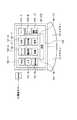
図2の例においては、LCDコントローラ56、LCDパネル57、バックライト58、タッチパッドコントローラ59、タッチパッド11、左ボタン12、右ボタン13、および機能ボタン14などを、個別に配置するようにしたが、これらを1つのブロックにまとめて収容するようにすることもできる。図15は、この場合の内部の構成例を表している。すなわち、この構成例においては、外部バス54に対して、タッチパッドブロック141が接続されている。本体2のその他の構成は、LCDコントローラ56、LCDパネル57、バックライト58、タッチパッドコントローラ59、タッチパッド11、左ボタン12、右ボタン13、および機能ボタン14などが省略されている点を除き、図2における場合と同様である。  In the example of FIG. 2, theLCD controller 56, theLCD panel 57, thebacklight 58, thetouch pad controller 59, thetouch pad 11, theleft button 12, theright button 13, and thefunction buttons 14 are arranged individually. However, these can be accommodated together in one block. FIG. 15 shows an internal configuration example in this case. That is, in this configuration example, thetouch pad block 141 is connected to the external bus 54. Other configurations of themain body 2 except that theLCD controller 56, theLCD panel 57, thebacklight 58, thetouch pad controller 59, thetouch pad 11, theleft button 12, theright button 13, and thefunction buttons 14 are omitted. This is the same as in FIG.

図16は、タッチパッドブロック141の内部の構成例を表している。CPU161は、ROM162に記憶されているプログラムに従って各種の処理を実行する。RAM163には、CPU161が実行するプログラムやデータなどが適宜記憶される。これらのCPU161、ROM162、およびRAM163は、内部バス164を介して相互に接続されている。この内部バス164にはまた、タッチパッドコントローラ59、LCDコントローラ56、およびRTC166が接続されている。タッチパッドコントローラ59は、タッチパッド11からの入力に対応する座標データを出力するようになされているとともに、左ボタン12、右ボタン13、または機能ボタン14の操作に対応する信号を出力する。  FIG. 16 shows an example of the internal configuration of thetouch pad block 141. TheCPU 161 executes various processes according to programs stored in theROM 162. TheRAM 163 appropriately stores programs executed by theCPU 161, data, and the like. TheseCPU 161,ROM 162, andRAM 163 are connected to each other via an internal bus 164. The internal bus 164 is also connected with atouch pad controller 59, anLCD controller 56, and anRTC 166. Thetouch pad controller 59 outputs coordinate data corresponding to the input from thetouch pad 11 and outputs a signal corresponding to the operation of theleft button 12, theright button 13, or thefunction button 14.

LCDコントローラ56は、バックライト58とLCD57を制御する。LCD57は、上述した場合と同様に、タッチパッド11の後方に配置されている。RTC166は計時動作を行い、時刻情報を出力する。バッテリ165は、タッチパッドブロック141の各部に必要な電力を供給している。従って、このタッチパッドブロック141は、本体2の電源がオフされていたり、CPU52やCPU64のOSが起動されていない状態においても使用可能となっている。内部バス164は、外部バス54と接続されている。  TheLCD controller 56 controls thebacklight 58 and theLCD 57. TheLCD 57 is arranged behind thetouch pad 11 as in the case described above. TheRTC 166 performs a timekeeping operation and outputs time information. Thebattery 165 supplies necessary power to each part of thetouch pad block 141. Accordingly, thetouch pad block 141 can be used even when the power of themain body 2 is turned off or the OS of theCPU 52 or theCPU 64 is not activated. The internal bus 164 is connected to the external bus 54.

なお、バッテリ165に代えて、本体2側のバッテリ76からタッチパッドブロック141に電力を供給するようにしてもよい。ただし、この場合においても、本体2側が実質的に非動作状態とされていたとしても、タッチパッドブロック141は単独で使用可能とされる。  Instead of thebattery 165, power may be supplied from thebattery 76 on themain body 2 side to thetouch pad block 141. However, even in this case, even if themain body 2 side is substantially inoperative, thetouch pad block 141 can be used alone.

このようにタッチ操作部9がブロック化された場合においても、その動作は、基本的に、上述した場合と同様に、図3と図4のフローチャートに示すように実行される。ただし、その処理は、本体2のCPU52により実行されるのではなく、タッチパッドブロック141内のCPU161により実行される。  Even when thetouch operation unit 9 is blocked as described above, the operation is basically executed as shown in the flowcharts of FIGS. 3 and 4 as in the case described above. However, the process is not executed by theCPU 52 of themain body 2 but by theCPU 161 in thetouch pad block 141.

例えば、図3のステップS1において、タッチパッドブロック141内のCPU161は、機能ボタン14が操作されたか否かを判定し、操作されている場合には、ステップS6に進み、機能選択処理を実行する。すなわち、CPU161は、図4のフローチャートに示したステップS11乃至ステップS21の処理を実行する。その詳細は、上述した場合と同様であるので、その説明はここでは省略する。  For example, in step S1 of FIG. 3, theCPU 161 in thetouchpad block 141 determines whether or not thefunction button 14 has been operated. If thefunction button 14 has been operated, the process proceeds to step S6 to execute a function selection process. . That is, theCPU 161 executes the processing from step S11 to step S21 shown in the flowchart of FIG. Since the details are the same as those described above, the description thereof is omitted here.

ステップS1において、機能ボタン14が操作されていないと判定された場合、CPU161は、ステップS2において、タッチパッド11が操作されたか否かを判定し、操作されている場合には、ステップS7において、座標データ出力処理を実行する。すなわち、タッチパッド11が操作されると、タッチパッドコントローラ59は、その操作に対応する座標データを出力する。CPU161は、この座標データを、内部バス164と外部バス54を介してマイクロコントローラ54のCPU52に出力する。  If it is determined in step S1 that thefunction button 14 has not been operated, theCPU 161 determines in step S2 whether or not thetouch pad 11 has been operated. If it has been operated, in step S7. Execute coordinate data output processing. That is, when thetouch pad 11 is operated, thetouch pad controller 59 outputs coordinate data corresponding to the operation. TheCPU 161 outputs this coordinate data to theCPU 52 of the microcontroller 54 via the internal bus 164 and the external bus 54.

ステップS2において、タッチパッド11が操作されていないと判定された場合、CPU161は、ステップS3において、左ボタン12または右ボタン13が操作されたか否かを判定し、操作された場合には、ステップS8において、信号出力処理を実行する。すなわち、左ボタン12または右ボタン13が操作されたとき、タッチパッドコントローラ59が操作に対応する信号を出力する。CPU161は、この操作信号を内部バス164と外部バス54を介してCPU52に出力する。  If it is determined in step S2 that thetouch pad 11 has not been operated, theCPU 161 determines in step S3 whether or not theleft button 12 or theright button 13 has been operated. In S8, a signal output process is executed. That is, when theleft button 12 or theright button 13 is operated, thetouch pad controller 59 outputs a signal corresponding to the operation. TheCPU 161 outputs this operation signal to theCPU 52 via the internal bus 164 and the external bus 54.

ステップS3において、左ボタン12または右ボタン13が操作されていないと判定された場合、ステップS4に進み、CPU161は、メインのCPU52より表示すべきデータが供給されているか否かを判定する。表示すべきデータが供給されている場合には、ステップS5に進み、CPU161は、CPU52より供給されたデータをRAM163に一旦記憶させるとともに、それを適宜読み出して、LCDコントローラ56を介してLCD57に出力し、表示させる。  If it is determined in step S3 that theleft button 12 or theright button 13 is not operated, the process proceeds to step S4, and theCPU 161 determines whether data to be displayed is supplied from themain CPU 52 or not. If the data to be displayed is supplied, the process proceeds to step S5, where theCPU 161 temporarily stores the data supplied from theCPU 52 in theRAM 163, reads it out as appropriate, and outputs it to theLCD 57 via theLCD controller 56. And display.

ステップS4において、CPU52より表示すべきデータが供給されていないと判定された場合、ステップS5の処理はスキップされ、ステップS1の処理に戻り、それ以降の処理が繰り返し実行される。  If it is determined in step S4 that the data to be displayed is not supplied from theCPU 52, the process in step S5 is skipped, the process returns to step S1, and the subsequent processes are repeatedly executed.

図10、図11、図13、または図14に示すように構成した場合にも、タッチ操作部9をブロック化することができる。  Even when configured as shown in FIG. 10, FIG. 11, FIG. 13, or FIG. 14, thetouch operation unit 9 can be blocked.

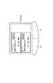
以上においては、タッチパッド11を本体2に一体的に(不可分に)形成するようにしたが、PCカードとして、別体として構成するようにすることもできる。図17は、この場合の構成例を表している。すなわち、この構成例においては、本体2の左ボタン12と右ボタン13が配置されている平面の近傍の前方端面には、スロット231が形成されており、ユーザは、このスロット231にPCカード240を挿入することができるようになされている。PCカード240は、左ボタン241と右ボタン242を有し、PCカード240をスロット231から本体2に装着したとき、左ボタン241は、本体2の左ボタン12の下方に位置し、右ボタン242は、右ボタン13の下方に位置し、ユーザが左ボタン12を操作したとき、左ボタン241が操作され、ユーザが右ボタン13を操作したとき、右ボタン242が操作されるようになされている。そして、図1の実施の形態において、タッチパッド11が形成されていた部分には、孔232が形成されおり、PCカード240をスロット231から本体2に装着したとき、PCカード240のタッチパッド243が孔232から外部に露出し、ユーザは、孔232を介してタッチパッド243を操作できるようになされている。  In the above description, thetouch pad 11 is integrally (inseparably) formed on themain body 2, but may be configured as a separate PC card. FIG. 17 shows a configuration example in this case. That is, in this configuration example, a slot 231 is formed on the front end surface of themain body 2 in the vicinity of the plane on which theleft button 12 and theright button 13 are arranged, and the user can insert thePC card 240 into the slot 231. Has been made so that it can be inserted. ThePC card 240 has aleft button 241 and aright button 242. When thePC card 240 is inserted into themain body 2 from the slot 231, theleft button 241 is positioned below theleft button 12 of themain body 2 and theright button 242. Is located below theright button 13, and when the user operates theleft button 12, theleft button 241 is operated, and when the user operates theright button 13, theright button 242 is operated. . In the embodiment of FIG. 1, ahole 232 is formed in the portion where thetouch pad 11 has been formed. When thePC card 240 is inserted into themain body 2 from the slot 231, thetouch pad 243 of thePC card 240 is formed. Is exposed to the outside through thehole 232, and the user can operate thetouch pad 243 through thehole 232.

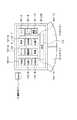
図18は、図17に示した携帯型パーソナルコンピュータ1の内部の構成例を表している。この構成例においては、図2と図12に示したLCDコントローラ56、LCD57、バックライト58、タッチパッドコントローラ59、タッチパッド11、左ボタン12、右ボタン13、および機能ボタン14が省略された構成となっている。  FIG. 18 shows an example of the internal configuration of the portablepersonal computer 1 shown in FIG. In this configuration example, theLCD controller 56,LCD 57,backlight 58,touch pad controller 59,touch pad 11, leftbutton 12,right button 13, andfunction buttons 14 shown in FIGS. 2 and 12 are omitted. It has become.

その代わりに、図18の例においては、PCカード240が本体2に装着されたとき、インタフェース251を介して内部バス50に接続されるようになされている。その他の構成は、図2または図12に示した場合と同様である。  Instead, in the example of FIG. 18, when thePC card 240 is mounted on themain body 2, it is connected to the internal bus 50 via theinterface 251. Other configurations are the same as those shown in FIG. 2 or FIG.

図19は、PCカード240の内部の構成例を表している。CPU261は、ROM262に記憶されているプログラムに従って各種の処理を実行する。RAM263には、CPU261が各種の処理を実行する上において必要なプログラムやデータが適宜記憶される。タッチパッドコントローラ265には、左ボタン241と右ボタン242の出力が供給されている。タッチパッドコントローラ265は、タッチパッド243が操作されたとき、その座標データを検出する。LCDコントローラ266は、LCD268を制御して所定の画像を表示させるとともに、LCD268の後方に配置されたバックライト267を駆動し、LCD268を照明させる。LCD268は、タッチパッド243の後方に配置されているが、タッチパッド243は、タッチパッド11と同様に、透明な材料により形成されているので、ユーザは、タッチパッド243を介してLCD268の画像を視認することが可能となされている。  FIG. 19 shows an internal configuration example of thePC card 240. TheCPU 261 executes various processes according to programs stored in theROM 262. TheRAM 263 appropriately stores programs and data necessary for theCPU 261 to execute various processes. Thetouch pad controller 265 is supplied with the outputs of theleft button 241 and theright button 242. Thetouch pad controller 265 detects the coordinate data when thetouch pad 243 is operated. TheLCD controller 266 controls theLCD 268 to display a predetermined image and drives abacklight 267 disposed behind theLCD 268 to illuminate theLCD 268. Although theLCD 268 is disposed behind thetouch pad 243, thetouch pad 243 is formed of a transparent material like thetouch pad 11, so that the user can view an image of theLCD 268 via thetouch pad 243. Visual recognition is possible.

RTC272は時刻情報を出力する。コネクタ270は、インタフェース251と接続され、入出力インタフェース269は、コネクタ270とCPU261の間のインタフェース処理を実行する。CPU261、ROM262、RAM263、タッチパッドコントローラ265、LCDコントローラ266、RTC272、および入出力インタフェース269は、それぞれ内部バス264を介して相互に接続されている。バッテリ271は、PCカード240の各部に必要な電力を供給している。  TheRTC 272 outputs time information. Theconnector 270 is connected to theinterface 251, and the input /output interface 269 executes interface processing between theconnector 270 and theCPU 261. TheCPU 261,ROM 262,RAM 263,touch pad controller 265,LCD controller 266,RTC 272, and input /output interface 269 are connected to each other via an internal bus 264. Thebattery 271 supplies necessary power to each part of thePC card 240.

次に、図20と図21のフローチャートを参照して、その動作について説明する。最初に、ステップS41において、PCカード240のCPU261は、PCカード240が本体2に装着されたか否かを判定する。PCカード240が、本体2に装着されたか否かは、コネクタ270を介して本体2のCPU52と通信できるか否かから判定することができる。ステップS41において、PCカード240が本体2に対して装着されていないと判定された場合、ステップS42に進み、CPU261は、PDA(Personal Digital Assistant)としての処理を実行する。  Next, the operation will be described with reference to the flowcharts of FIGS. First, in step S <b> 41, theCPU 261 of thePC card 240 determines whether or not thePC card 240 is attached to themain body 2. Whether or not thePC card 240 is attached to themain body 2 can be determined from whether or not thePC card 240 can communicate with theCPU 52 of themain body 2 via theconnector 270. If it is determined in step S41 that thePC card 240 is not attached to themain body 2, the process proceeds to step S42, and theCPU 261 executes processing as a PDA (Personal Digital Assistant).

例えば、ユーザが、ペンを用いてタッチパッド243を操作すると、その座標データが、タッチパッドコントローラ265を介してCPU261に供給される。CPU261は、この座標データに対応する軌跡をLCDコントローラ266を介してLCD268に出力し、表示させる。これにより、ユーザは、ペンで入力した軌跡を目で確認することができる。ユーザが、ペンで所定の文字を入力したとき、CPU261は、入力された座標データに基づいて文字認識処理を行い、認識した結果得られた文字をLCDコントローラ266を介してLCD268に表示させる。ユーザは、認識された結果表示された文字を見て、誤っていれば、再度入力を行うなどして、所定の文字情報を入力することができる。そして、所定の指令が入力されたとき、CPU261は、入力された文字データをRAM263に供給し、記憶させる。  For example, when the user operates thetouch pad 243 using a pen, the coordinate data is supplied to theCPU 261 via thetouch pad controller 265. TheCPU 261 outputs a locus corresponding to the coordinate data to theLCD 268 via theLCD controller 266 for display. Thereby, the user can confirm the locus | trajectory input with the pen with eyes. When the user inputs a predetermined character with the pen, theCPU 261 performs character recognition processing based on the input coordinate data, and displays the character obtained as a result of the recognition on theLCD 268 via theLCD controller 266. The user can input predetermined character information by looking at the characters displayed as a result of recognition and entering the characters again if they are incorrect. When a predetermined command is input, theCPU 261 supplies the input character data to theRAM 263 for storage.

RAM263に記憶されたデータは、バッテリ271によりバックアップされているため、PCカード240を本体1から分離した状態で使用していたとしても、そのデータが消去されるようなことはない。また、バッテリ271が、各部に必要な電力を供給しているので、PCカード240が、本体2から分離独立された状態であったとしても、ユーザは、PCカード240をPDAとして機能させることができる。さらに、仮に、PCカード240が、本体2に対して装着された状態であり、本体2側の電源がオフされた状態であったり、OSが起動されていない状態であったとしても、PCカード240は、単独で使用することができる。  Since the data stored in theRAM 263 is backed up by thebattery 271, even if thePC card 240 is used while being separated from themain body 1, the data is not erased. Further, since thebattery 271 supplies necessary power to each unit, even if thePC card 240 is separated and independent from themain body 2, the user can cause thePC card 240 to function as a PDA. it can. Further, even if thePC card 240 is mounted on themain body 2 and the power supply on themain body 2 side is turned off or the OS is not activated, thePC card 240 can be used alone.

ステップS41において、PCカード240が本体2に装着されていると判定された場合、ステップS43に進み、CPU261は、キーボード4のうち、予め割り当てられている所定のキーが操作されたか否かを判定する。すなわち、キーボード4の所定のキーが操作されたとき、本体2のキーボードコントローラ61は、操作されたキーに対応する信号をCPU52に出力する。CPU52は、入力されたキーを示す信号を、インタフェース251を介してPCカード240に出力する。  If it is determined in step S41 that thePC card 240 is attached to themain body 2, the process proceeds to step S43, and theCPU 261 determines whether or not a predetermined key assigned to thekeyboard 4 has been operated. To do. That is, when a predetermined key on thekeyboard 4 is operated, thekeyboard controller 61 of themain body 2 outputs a signal corresponding to the operated key to theCPU 52. TheCPU 52 outputs a signal indicating the input key to thePC card 240 via theinterface 251.

PCカード240においては、本体2のCPU52から供給されてきた信号をコネクタ270、入出力インタフェース269を介してCPU261が受け取る。CPU261は、この受け取った信号から操作されたキーが何であるかを判定する。  In thePC card 240, theCPU 261 receives a signal supplied from theCPU 52 of themain body 2 via theconnector 270 and the input /output interface 269. TheCPU 261 determines what the operated key is from the received signal.

ステップS43において、予め定められている所定の割当キーが操作されていないと判定された場合、ステップS44に進み、CPU261は、タッチパッド243が操作されたか否かを判定する。タッチパッド243が操作された場合には、ステップS47に進み、CPU261は、操作に対応する座標データを出力する処理を実行する。すなわち、タッチパッド243が操作されると、タッチパッドコントローラ265は、操作位置に対応する座標データを出力する。CPU261は、この座標データを入出力インタフェース159、コネクタ270を介して本体2に出力する。  If it is determined in step S43 that a predetermined predetermined assignment key has not been operated, the process proceeds to step S44, and theCPU 261 determines whether or not thetouch pad 243 has been operated. When thetouch pad 243 is operated, the process proceeds to step S47, and theCPU 261 executes a process of outputting coordinate data corresponding to the operation. That is, when thetouch pad 243 is operated, thetouch pad controller 265 outputs coordinate data corresponding to the operation position. TheCPU 261 outputs this coordinate data to themain body 2 via the input / output interface 159 and theconnector 270.

本体2において、CPU52は、インタフェース251を介して、この座標データを受け取ると、その座標データに対応する処理を実行する。すなわち、このとき、CPU52は、図1のタッチパッド11が操作された場合と同様の処理を実行することができる。  In themain body 2, when receiving the coordinate data via theinterface 251, theCPU 52 executes processing corresponding to the coordinate data. That is, at this time, theCPU 52 can execute the same processing as when thetouch pad 11 of FIG. 1 is operated.

ステップS44において、タッチパッド243が操作されていないと判定された場合、ステップS45に進み、CPU261は、左ボタン241または右ボタン242が操作されたか否かを判定する。左ボタン241または右ボタン242が操作された場合には、ステップS48に進み、CPU261は、対応する信号を出力する処理を実行する。  If it is determined in step S44 that thetouch pad 243 is not operated, the process proceeds to step S45, and theCPU 261 determines whether theleft button 241 or theright button 242 is operated. When theleft button 241 or theright button 242 is operated, the process proceeds to step S48, and theCPU 261 executes processing for outputting a corresponding signal.

すなわち、ユーザが、図17に示す左ボタン12または右ボタン13を操作すると、その下方に配置されている左ボタン241または右ボタン242が操作される。従って、このとき、PCカード240のタッチパッドコントローラ265は、左ボタン241または右ボタン242が操作された信号を出力する。CPU261は、この操作信号を入出力インタフェース269、コネクタ270を介して、本体2側に出力する。  That is, when the user operates theleft button 12 or theright button 13 shown in FIG. 17, theleft button 241 or theright button 242 disposed below the button is operated. Accordingly, at this time, thetouch pad controller 265 of thePC card 240 outputs a signal indicating that theleft button 241 or theright button 242 is operated. TheCPU 261 outputs this operation signal to themain body 2 side via the input /output interface 269 and theconnector 270.

本体2側において、CPU52は、PCカード240からの操作信号をインタフェース251を介して受け取ると、その操作に対応する処理を実行する。すなわち、この場合においても、図1の左ボタン12または右ボタン13が操作された場合と同様の処理が行われる。  On themain body 2 side, when receiving an operation signal from thePC card 240 via theinterface 251, theCPU 52 executes processing corresponding to the operation. That is, also in this case, the same processing as when theleft button 12 or theright button 13 in FIG. 1 is operated is performed.

ステップS45において、左ボタン241または右ボタン242が操作されていないと判定された場合、ステップS46に進み、CPU261は、本体2のCPU52より表示すべきデータが送られてきたか否かを判定する。表示すべきデータが送られてきた場合には、ステップS49に進み、CPU261は、このデータをコネクタ270、入出力インタフェース269を介して受信すると、これをLCDコントローラ266を介してLCD268に表示させる。本体2からのデータの表示が、ステップS50において、ユーザが終了を指令するまで継続される。ステップS46において、本体2より表示すべきデータが送られてきていないと判定された場合、またはステップS50において、本体2より供給されてきたデータの表示の終了が指令されたと判定された場合、ステップS43に戻り、それ以降の処理が繰り返し実行される。  If it is determined in step S45 that theleft button 241 or theright button 242 is not operated, the process proceeds to step S46, and theCPU 261 determines whether data to be displayed has been sent from theCPU 52 of themain body 2. If the data to be displayed has been sent, the process proceeds to step S49. When theCPU 261 receives this data via theconnector 270 and the input /output interface 269, theCPU 261 displays it on theLCD 268 via theLCD controller 266. The display of data from themain body 2 is continued until the user commands an end in step S50. If it is determined in step S46 that data to be displayed has not been sent from themain body 2, or if it is determined in step S50 that the display of data supplied from themain body 2 has been instructed, step Returning to S43, the subsequent processing is repeatedly executed.

ステップS43において、キーボード4のキーのうち、機能選択メニューを表示させる機能が割り当てられた所定のキーが操作されたと判定された場合、ステップS51に進み、CPU261は、LCDコントローラ266を制御し、LCD268に、例えば、図22に示すようなメニュー画面を表示させる。この表示例においては、図10に示したテンキーボタン101−1乃至機能設定ボタン101−12のうちの、機能設定ボタン101−12に代えて、転送ボタン101−14が表示されている。  If it is determined in step S43 that a predetermined key to which a function selection menu display function is assigned among the keys on thekeyboard 4 has been operated, the process proceeds to step S51, where theCPU 261 controls theLCD controller 266 and theLCD 268. For example, a menu screen as shown in FIG. 22 is displayed. In this display example, a transfer button 101-14 is displayed instead of the function setting button 101-12 among the numeric keypad buttons 101-1 to 101-12 shown in FIG.

次に、ステップS52において、CPU261は、テンキーボタン101−1乃至転送ボタン101−14の選択ボタンのうち、いずれかが操作されたか否かを判定する。選択ボタンが操作されたか否かの判定処理は、ユーザがタッチパッド243を操作すると、タッチパッドコントローラ265から、その座標データが出力されるので、CPU261は、この座標データをLCD268に表示しているボタンの座標データと比較することで行うことができる。いずれの選択ボタンも操作されていない場合には、ステップS60に進み、メニュー画面の表示処理を終了させるために割り当てられている所定のキーが操作されたか否かが判定され、そのキーが操作されていない場合には、ステップS52に戻り、それ以降の処理が繰り返し実行される。ステップS60において、メニュー画面の表示処理を終了させる機能が割り当てられているキーが操作されたと判定された場合、ステップS61に進み、CPU261は、メニュー表示処理を終了させる。すなわち、このとき、CPU261は、LCDコントローラ266を制御し、LCD268のメニュー画面を消去させる。その後、ステップS43に戻り、それ以降の処理が繰り返し実行される。  Next, in step S52, theCPU 261 determines whether any of the selection buttons of the numeric keypad button 101-1 to the transfer button 101-14 has been operated. In the determination process of whether or not the selection button has been operated, when the user operates thetouch pad 243, the coordinate data is output from thetouch pad controller 265, so theCPU 261 displays the coordinate data on theLCD 268. This can be done by comparing with the coordinate data of the button. If none of the selection buttons has been operated, the process proceeds to step S60, where it is determined whether or not a predetermined key assigned for ending the menu screen display process has been operated, and the key is operated. If not, the process returns to step S52, and the subsequent processing is repeatedly executed. If it is determined in step S60 that the key to which the function for ending the menu screen display process is assigned has been operated, the process proceeds to step S61, and theCPU 261 ends the menu display process. That is, at this time, theCPU 261 controls theLCD controller 266 to erase the menu screen of theLCD 268. Thereafter, the process returns to step S43, and the subsequent processing is repeatedly executed.

ステップS52において、選択ボタンのうち、いずれかが操作されたと判定された場合、ステップS53に進み、CPU261は、LCDコントローラ266を制御し、LCD268に表示されている選択ボタンのうち、操作された選択ボタンをハイライト表示させる。例えば、図22に示すようなメニュー画面が表示されている状態において、転送ボタン101−14が操作されたとき、転送ボタン101−14がハイライト表示される。  If it is determined in step S52 that any one of the selection buttons has been operated, the process proceeds to step S53, where theCPU 261 controls theLCD controller 266 to select the operated button among the selection buttons displayed on theLCD 268. Highlight the button. For example, when the transfer button 101-14 is operated in a state where the menu screen as shown in FIG. 22 is displayed, the transfer button 101-14 is highlighted.

次に、ステップS54において、CPU261は、決定ボタン112が操作されたか否かを判定する。決定ボタン112が操作されていない場合には、ステップS55に進み、他の選択ボタンが操作されたか否かが判定される。他の選択ボタンが操作された場合には、ステップS53に戻り、それまでハイライト表示されていたボタンに代えて、新たに操作された選択ボタンがハイライト表示される。ステップS55において、他の選択ボタンが操作されていないと判定された場合には、ステップS54に戻り、再び、決定ボタン112が操作されたか否かが判定される。  Next, in step S54, theCPU 261 determines whether or not theenter button 112 has been operated. If thedetermination button 112 has not been operated, the process proceeds to step S55, and it is determined whether or not another selection button has been operated. If another selection button is operated, the process returns to step S53, and the newly operated selection button is highlighted instead of the button that has been highlighted so far. If it is determined in step S55 that no other selection button has been operated, the process returns to step S54, and it is determined again whether or not theenter button 112 has been operated.

ステップS54において、決定ボタン112が操作されたと判定された場合、ステップS56に進み、いま選択されているのは(ハイライト表示されているのは)、非表示ボタン101−13であるか否かが判定される。いま、選択されているのが非表示ボタン101−13である場合には、ステップS61に進み、CPU261は、メニュー表示処理を実行する。そして、ステップS43に戻り、それ以降の処理を繰り返し実行する。  If it is determined in step S54 that theenter button 112 has been operated, the process proceeds to step S56, and it is determined whether or not the currently selected (highlighted) button is the non-display button 101-13. Is determined. If the non-display button 101-13 is currently selected, the process proceeds to step S61, and theCPU 261 executes menu display processing. Then, the process returns to step S43, and the subsequent processing is repeatedly executed.

ステップS56において、いま選択されているのは非表示ボタン101−13ではないと判定された場合は、ステップS57に進み、CPU261は、LCDコントローラ266を制御し、そのとき選択されている選択ボタンに対応する画像をLCD268に出力し、表示させる。そして、CPU261は、ステップS58において、LCD268に表示させた画像に基づいて、所定の機能を実行する処理を行う。  If it is determined in step S56 that the currently selected button is not the non-display button 101-13, the process proceeds to step S57, and theCPU 261 controls theLCD controller 266 to select the currently selected button. The corresponding image is output to theLCD 268 and displayed. In step S58, theCPU 261 performs a process of executing a predetermined function based on the image displayed on theLCD 268.

例えば、ユーザが、転送ボタン101−14を操作すると、その操作信号が、タッチパッドコントローラ265からCPU261に通知される。このとき、CPU261は、RAM263に記憶されているデータ(図20のステップS42の処理で記憶させたデータ)を読み出し、入出力インタフェース269、コネクタ270を介して本体2側に転送させる。本体2側のCPU52は、このデータを受信したとき、それをRAM53に記憶させる。すなわち、これにより、PCカード240が、本体2から離脱された状態で入力されたデータ、あるいは本体2にPCカード240が装着されてはいるが、本体2の電源がオフされていたり、本体2側のOSが起動されていない状態において、PCカード240で記録したデータが、PCカード240から本体2側に転送され、本体2側のRAM53に記憶される。  For example, when the user operates the transfer button 101-14, the operation signal is notified from thetouch pad controller 265 to theCPU 261. At this time, theCPU 261 reads out the data stored in the RAM 263 (data stored in the process of step S42 in FIG. 20) and transfers it to themain body 2 side via the input /output interface 269 and theconnector 270. When theCPU 52 on themain body 2 side receives this data, it stores it in theRAM 53. That is, as a result, the data entered when thePC card 240 is detached from themain body 2 or themain body 2 is turned off although thePC card 240 is attached to themain body 2 or themain body 2 is turned off. In a state where the OS on the side is not activated, the data recorded by thePC card 240 is transferred from thePC card 240 to themain body 2 side and stored in theRAM 53 on themain body 2 side.

ステップS59において、選択された機能の実行処理の終了が、ユーザより指令されたと判定されるまで、ステップS58の処理は繰り返し実行される。ステップS59において、選択された機能の処理の終了が、ユーザより指令されたと判定された場合、CPU261は選択された機能の実行処理を終了させる。その後、ステップS51に戻り、CPU261は、メニュー画面表示処理を実行する。そして、上述した場合と同様の処理が繰り返される。  In step S59, the process of step S58 is repeatedly executed until it is determined that the end of the execution process of the selected function is instructed by the user. In step S59, when it is determined that the end of the process of the selected function is instructed by the user, theCPU 261 ends the execution process of the selected function. Thereafter, the process returns to step S51, and theCPU 261 executes menu screen display processing. Then, the same processing as described above is repeated.

以上のようにして、この実施の形態の場合、PCカード240が、本体2側と独立に動作させることが可能であるので、本体2側の電源をオフしたり、そのOSを起動していない状態においても、常時、動作状態とさせておくことが可能となり、本体2側の動作状態に依存せずに、自律的に、各種機能(例えば、スケジューラ、電子ペットの飼育ゲームなど)を実行させておくことが可能となる。  As described above, in the case of this embodiment, thePC card 240 can be operated independently from themain body 2 side, so the power supply on themain body 2 side is not turned off or its OS is not started. Even in the state, it is possible to always keep the operation state, and autonomously execute various functions (for example, a scheduler, an electronic pet breeding game, etc.) without depending on the operation state on themain body 2 side. It is possible to keep.

以上においては、キーボード4は、本体2側の入力にのみ用いるようにしたが、PCカード240側の入力にも用いるようにしてもよい。  In the above description, thekeyboard 4 is used only for input on themain body 2 side, but may be used for input on thePC card 240 side.

また、タッチパッド11または243側のLCD11または268には、機能の選択ボタンを表示させるようにしたが、プログラムの選択ボタン(例えば、アイコン)などを表示させるようにしてもよい。  In addition, although the function selection button is displayed on theLCD 11 or 268 on thetouch pad 11 or 243 side, a program selection button (for example, an icon) or the like may be displayed.

本発明を適用した携帯型パーソナルコンピュータ1の外観の構成を示す斜視図である。1 is a perspective view showing an external configuration of a portablepersonal computer 1 to which the present invention is applied.図1の携帯型パーソナルコンピュータ1の内部の構成例を示すブロック図である。FIG. 2 is a block diagram illustrating an internal configuration example of the portablepersonal computer 1 of FIG. 1.図1の携帯型パーソナルコンピュータ1の動作を説明するフローチャートである。4 is a flowchart for explaining the operation of the portablepersonal computer 1 of FIG. 1.図3のステップS6の機能選択処理の詳細を説明するフローチャートである。It is a flowchart explaining the detail of the function selection process of step S6 of FIG.図2のLCD57の表示例を示す図である。FIG. 3 is a diagram showing a display example of anLCD 57 in FIG. 2.図2のLCD57の表示例を示す図である。FIG. 3 is a diagram showing a display example of anLCD 57 in FIG. 2.図2のLCD57の表示例を示す図である。FIG. 3 is a diagram showing a display example of anLCD 57 in FIG. 2.図2のLCD57の表示例を示す図である。FIG. 3 is a diagram showing a display example of anLCD 57 in FIG. 2.時計機能の処理を説明するフローチャートである。It is a flowchart explaining the process of a timepiece function.図2のLCD57の表示例を示す図である。FIG. 3 is a diagram showing a display example of anLCD 57 in FIG. 2.他の機能ボタンの例を示す図である。It is a figure which shows the example of another function button.図11の機能ボタンを設けた場合の携帯型パーソナルコンピュータ1の内部の構成例を示すブロック図である。It is a block diagram which shows the example of an internal structure of the portablepersonal computer 1 at the time of providing the function button of FIG.機能ボタンのさらに他の例を示す図である。It is a figure which shows the further another example of a function button.図2のLCD57の表示例を示す図である。FIG. 3 is a diagram showing a display example of anLCD 57 in FIG. 2.本発明を適用した携帯型パーソナルコンピュータ1の内部の他の構成例を示すブロック図である。It is a block diagram which shows the other structural example of the inside of the portablepersonal computer 1 to which this invention is applied.図15のタッチパッドブロック141の内部の構成例を示すブロック図である。FIG. 16 is a block diagram illustrating an internal configuration example of thetouch pad block 141 in FIG. 15.本発明を適用した携帯型パーソナルコンピュータ1の他の外観構成を示す斜視図である。It is a perspective view which shows the other external appearance structure of the portablepersonal computer 1 to which this invention is applied.図17の携帯型パーソナルコンピュータ1の内部の構成例を示すブロック図である。FIG. 18 is a block diagram illustrating an internal configuration example of the portablepersonal computer 1 in FIG. 17.図17のPCカード240の内部の構成例を示すブロック図である。It is a block diagram which shows the example of an internal structure of thePC card 240 of FIG.図17のPCカード240の動作を説明するフローチャートである。It is a flowchart explaining the operation | movement of thePC card 240 of FIG.図17のPCカード240の動作を説明するフローチャートである。It is a flowchart explaining the operation | movement of thePC card 240 of FIG.図19のLCD268の表示例を示す図である。FIG. 20 is a diagram showing a display example of theLCD 268 in FIG. 19.

符号の説明Explanation of symbols

1 携帯型パーソナルコンピュータ, 2 本体, 3 表示部, 4 キーボード, 5 バッテリパック, 8 スロット, 9 タッチ操作部, 11 タッチパッド, 12 左ボタン, 13 右ボタン, 14 機能ボタン, 15 マイクロホン, 16 スピーカ, 41 LCD, 52 CPU, 53 RAM, 55 HDD, 56 LCDコントローラ, 57 LCD, 58 バックライト, 59 タッチパッドコントローラ, 61 キーボードコントローラ, 66 CPU, 77 LCDコントローラ  DESCRIPTION OFSYMBOLS 1 Portable personal computer, 2 Main body, 3 Display part, 4 Keyboard, 5 Battery pack, 8 Slot, 9 Touch operation part, 11 Touchpad, 12 Left button, 13 Right button, 14 Function button, 15 Microphone, 16 Speaker, 41 LCD, 52 CPU, 53 RAM, 55 HDD, 56 LCD controller, 57 LCD, 58 backlight, 59 touchpad controller, 61 keyboard controller, 66 CPU, 77 LCD controller

Claims (1)

Translated fromJapanese
所定の入力を行う第1の入力手段と、
前記第1の入力手段によって入力された情報を処理する処理手段と、
前記処理手段によって処理された情報を表示する第1の表示手段と、
前記処理手段によって処理された情報を表示する第2の表示手段と
を備える情報処理装置。
First input means for performing predetermined input;
Processing means for processing information input by the first input means;
First display means for displaying information processed by the processing means;
An information processing apparatus comprising: second display means for displaying information processed by the processing means.
JP2006088489A1998-12-162006-03-28Information processorPendingJP2006221665A (en)

Priority Applications (1)

Application NumberPriority DateFiling DateTitle
JP2006088489AJP2006221665A (en)1998-12-162006-03-28Information processor

Applications Claiming Priority (3)

Application NumberPriority DateFiling DateTitle
JP357263981998-12-16
JP79000991999-03-24
JP2006088489AJP2006221665A (en)1998-12-162006-03-28Information processor

Related Parent Applications (1)

Application NumberTitlePriority DateFiling Date
JP33908399ADivisionJP2000339097A (en)1998-12-161999-11-30Information processor, its controlling method and recording medium

Related Child Applications (1)

Application NumberTitlePriority DateFiling Date
JP2011208368ADivisionJP5522138B2 (en)1998-12-162011-09-26 Information processing device

Publications (1)

Publication NumberPublication Date
JP2006221665Atrue JP2006221665A (en)2006-08-24

Family

ID=36983898

Family Applications (1)

Application NumberTitlePriority DateFiling Date
JP2006088489APendingJP2006221665A (en)1998-12-162006-03-28Information processor

Country Status (1)

CountryLink
JP (1)JP2006221665A (en)

Cited By (4)

* Cited by examiner, † Cited by third party
Publication numberPriority datePublication dateAssigneeTitle
JP2008165390A (en)*2006-12-272008-07-17Toshiba Corp Personal computer and its illumination control method
KR100896129B1 (en)2008-10-142009-05-07허윤석 Notebook computer with touch screen in palm rest area and its control method
WO2008133996A3 (en)*2007-04-272010-03-18Hewlett-Packard Development Company, L.P.Computing device with multiple displays
JP2010079715A (en)*2008-09-262010-04-08Nec Personal Products Co LtdInformation processing apparatus

Cited By (7)

* Cited by examiner, † Cited by third party
Publication numberPriority datePublication dateAssigneeTitle
JP2008165390A (en)*2006-12-272008-07-17Toshiba Corp Personal computer and its illumination control method
WO2008133996A3 (en)*2007-04-272010-03-18Hewlett-Packard Development Company, L.P.Computing device with multiple displays
DE112008001118B4 (en)*2007-04-272012-10-11Hewlett-Packard Development Co., L.P. Computing device with multiple displays
US10133317B2 (en)2007-04-272018-11-20Hewlett-Packard Development Company, L.P.Computing device with multiple displays
JP2010079715A (en)*2008-09-262010-04-08Nec Personal Products Co LtdInformation processing apparatus
KR100896129B1 (en)2008-10-142009-05-07허윤석 Notebook computer with touch screen in palm rest area and its control method
WO2010044591A3 (en)*2008-10-142010-07-22Huh Yoon-SukNotebook computer with a touch screen located on the palm rest area thereof, and control method thereof

Similar Documents

PublicationPublication DateTitle
JP5522138B2 (en) Information processing device
JP2000339097A (en)Information processor, its controlling method and recording medium
US7143355B2 (en)Information processing device for processing information based on a status monitoring program and method therefor
US9001046B2 (en)Mobile terminal with touch screen
JP2602001B2 (en) Personal communicator with shrinkable keyboard
TWI233041B (en)Touchscreen user interface
JP4545884B2 (en) Information processing apparatus, control method therefor, and computer-readable memory
JP2000137555A (en) Information processing apparatus and method, and recording medium
JP2004152217A (en)Display device with touch panel
CN111142674B (en)Control method and electronic equipment
CN114690887B (en) A feedback method and related device
JP2005092703A (en) Information processing device
JP2004362566A (en)System and method for facilitating composition of handwritten documents
JP3519007B2 (en) Information device having map information display function, map information display method, and recording medium recording map information display program
CN114690889A (en)Processing method of virtual keyboard and related equipment
CN114764304A (en)Screen display method
JP2006221665A (en)Information processor
CN107526567B (en)Information processing apparatus, input method, and storage medium
JP2015158828A (en)Electronic blackboard device
JP2019145058A (en)Information processing device
JP3449364B2 (en) Program starting device, program starting method, medium, and electronic device in electronic device
US10509556B2 (en)Display device
CN114690888A (en) An application interface processing method and related equipment
JP3241362B2 (en) Information input control device and method
JP2785194B2 (en) Personal information management method and device

Legal Events

DateCodeTitleDescription
A621Written request for application examination

Free format text:JAPANESE INTERMEDIATE CODE: A621

Effective date:20061127

A131Notification of reasons for refusal

Free format text:JAPANESE INTERMEDIATE CODE: A131

Effective date:20080430

A521Request for written amendment filed

Free format text:JAPANESE INTERMEDIATE CODE: A523

Effective date:20080630

A02Decision of refusal

Free format text:JAPANESE INTERMEDIATE CODE: A02

Effective date:20081211

A521Request for written amendment filed

Free format text:JAPANESE INTERMEDIATE CODE: A523

Effective date:20090203

A911Transfer to examiner for re-examination before appeal (zenchi)

Free format text:JAPANESE INTERMEDIATE CODE: A911

Effective date:20090217

A912Re-examination (zenchi) completed and case transferred to appeal board

Free format text:JAPANESE INTERMEDIATE CODE: A912

Effective date:20090319


[8]ページ先頭

©2009-2025 Movatter.jp