JP2006221376A - Plant emergency information display system and method, Web server - Google Patents
Plant emergency information display system and method, Web serverDownload PDFInfo
- Publication number
- JP2006221376A JP2006221376AJP2005033584AJP2005033584AJP2006221376AJP 2006221376 AJP2006221376 AJP 2006221376AJP 2005033584 AJP2005033584 AJP 2005033584AJP 2005033584 AJP2005033584 AJP 2005033584AJP 2006221376 AJP2006221376 AJP 2006221376A
- Authority
- JP
- Japan
- Prior art keywords
- plant
- web
- data
- server
- emergency
- Prior art date
- Legal status (The legal status is an assumption and is not a legal conclusion. Google has not performed a legal analysis and makes no representation as to the accuracy of the status listed.)
- Pending
Links
Images


Classifications
- Y—GENERAL TAGGING OF NEW TECHNOLOGICAL DEVELOPMENTS; GENERAL TAGGING OF CROSS-SECTIONAL TECHNOLOGIES SPANNING OVER SEVERAL SECTIONS OF THE IPC; TECHNICAL SUBJECTS COVERED BY FORMER USPC CROSS-REFERENCE ART COLLECTIONS [XRACs] AND DIGESTS
- Y02—TECHNOLOGIES OR APPLICATIONS FOR MITIGATION OR ADAPTATION AGAINST CLIMATE CHANGE
- Y02P—CLIMATE CHANGE MITIGATION TECHNOLOGIES IN THE PRODUCTION OR PROCESSING OF GOODS
- Y02P90/00—Enabling technologies with a potential contribution to greenhouse gas [GHG] emissions mitigation
- Y02P90/02—Total factory control, e.g. smart factories, flexible manufacturing systems [FMS] or integrated manufacturing systems [IMS]
Landscapes
- General Factory Administration (AREA)
- Testing And Monitoring For Control Systems (AREA)
- Management, Administration, Business Operations System, And Electronic Commerce (AREA)
Abstract
Translated fromJapaneseDescription
Translated fromJapanese本発明は、監視対象プラントの緊急時における情報を表示するための技術に関するものである。 The present invention relates to a technique for displaying information in an emergency of a plant to be monitored.
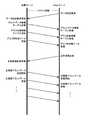
一般に、原子力発電所の緊急時における情報を表示するための緊急時情報表示システムは、図16に示す形態で構成される。 In general, an emergency information display system for displaying emergency information of a nuclear power plant is configured in the form shown in FIG.
この図16に示すように、発電所1内のプロセス計算機11は、発電会社専用回線2を介して発電会社データセンタ3内の収集サーバ31と接続されている。収集サーバ31は、発電会社データセンタ3内の収集サーバ用クライアント33に接続されると共に、通信事業者回線4を介して行政データセンタ5内の行政サーバ51と接続されている。行政サーバ51は、行政専用回線6を介して行政出先機関7内の行政クライアント71と接続されている。 As shown in FIG. 16, the
このうち、収集サーバ31と行政サーバ51は、一般的に「サーバ」と呼ばれる記憶容量の大きなコンピュータから構成されている。また、収集サーバ用クライアント33と行政クライアント71は、汎用のパーソナルコンピュータから構成されている。また、図16中では、簡略化の観点から、監視対象として、単一の発電所1のみが示されているが、実際には、監視対象となる複数の発電所が同様に接続されている。 Among these, the
このような構成を有する図16の緊急時情報表示システムの動作は次の通りである。すなわち、発電所1内のプロセス計算機11は、予め設定された一定の周期でプロセスデータを収集サーバ31に送信する。発電会社データセンタ3内の収集サーバ31は、発電所1内のプロセス計算機11から一定の周期で送信されるプロセスデータを収集し、収集したプロセスデータを収集サーバ用クライアント33に送信することにより、収集サーバ用クライアント33上にプロセスデータを画面表示させる。 The operation of the emergency information display system of FIG. 16 having such a configuration is as follows. That is, the
また、収集サーバ31は、プロセスデータの中から、緊急時に行政官庁に提供すべきデータを抽出し、通信事業者回線4を経由して行政データセンタ5内の行政サーバ51に送信する。原子力発電所の場合、このような行政サーバ51へのデータ送信は、原子力発電所の災害等の緊急時のみに行われる。さらに、緊急時のプロセスデータを受信した行政サーバ51は、行政専用回線6を経由してデータを行政クライアント71に送信することにより、行政クライアント71上にプロセスデータを画面表示させる。 Further, the
上記の動作により、原子力発電所の緊急時の情報は、発電所内のみでなく、発電会社の本社、行政官庁、および行政官庁出先機関などに設けられるデータセンタなどの緊急対策拠点でリアルタイムに表示することができる。 Through the above operation, emergency information of nuclear power plants is displayed in real time not only within the power plant, but also at emergency countermeasure bases such as data centers established at the headquarters of the power generation company, administrative agencies, and government agencies. be able to.
また、発電所等のプラントの緊急時に緊急対策拠点に情報を通知するための従来手法としては、プラントのプロセスデータを収集し、プロセスデータの値から緊急対策を要する異常発生と判断される場合に、収集したデータを予め送信先として設定された緊急対策拠点に電子メール等で自動送信する手法が存在している(例えば、特許文献1、2参照)。
しかしながら、上述したようなプラントの緊急時における従来の情報通知・表示手法には、次のような問題点がある。 However, the conventional information notification / display method at the time of plant emergency as described above has the following problems.
まず、図16に示す緊急時情報表示システムにおいては、発電会社の本社、行政官庁、および行政官庁出先機関などに予め設けられているデータセンタなどの緊急対策拠点で、緊急時に特定のプロセスデータを受信して表示することができるが、受信したプロセスデータが同一であっても、個々の緊急対策拠点における表示形式は異なるため、複数の緊急対策拠点間で完全に同一のプラント情報を共有することは困難である。 First, in the emergency information display system shown in FIG. 16, specific process data is stored in an emergency countermeasure base such as a data center provided in advance at the head office of a power generation company, an administrative agency, and a branch office of an administrative agency. Even if the received process data is the same, the display format at each emergency response site is different, so the same plant information must be shared among multiple emergency response sites. It is difficult.
すなわち、図16に示す原子力発電所の例において、行政出先機関7、発電会社データセンタ3、および発電所1内にそれぞれ設けられた計3箇所の緊急対策拠点間でプラント情報を完全に共有することは困難である。 That is, in the example of the nuclear power plant shown in FIG. 16, the plant information is completely shared among the three emergency countermeasure bases provided in the
また、緊急時にプロセスデータを自動送信する場合には、予め送信先として設定された緊急対策拠点に特定のプロセスデータを自動送信できる反面、それ以外の未設定の緊急対策拠点にプロセスデータを自動送信することはできないため、未設定の緊急対策拠点に対する情報の通知が遅延してしまう。特に、データを電子メールで送信する場合には、複数の緊急対策拠点に対してデータを同時に自動送信しても、受信したデータを画面表示する時間に差が生じる。したがって、複数の緊急対策拠点間でプラント情報を同時に共有することは困難である。 In addition, when process data is automatically transmitted in an emergency, specific process data can be automatically transmitted to an emergency countermeasure base set in advance as a transmission destination, while process data is automatically transmitted to other unconfigured emergency countermeasure bases. Since it cannot be performed, the notification of information to the emergency countermeasure bases that have not been set is delayed. In particular, when data is transmitted by e-mail, there is a difference in the time for displaying the received data on the screen even if the data is automatically transmitted simultaneously to a plurality of emergency countermeasure bases. Therefore, it is difficult to simultaneously share plant information among a plurality of emergency countermeasure bases.
なお、このようなプラントの緊急時情報通知・表示手法の問題点は、原子力発電所に限らず、プラントの緊急時に複数の緊急対策拠点間におけるプラント情報の共有が重要な各種のプラントを監視対象とする緊急時情報通知・表示手法に共通して存在する問題点である。 In addition, the problem of the emergency information notification / display method for plants is not limited to nuclear power plants, but various plants in which plant information is important to be shared among multiple emergency countermeasure bases in the event of a plant emergency are subject to monitoring. This is a common problem in the emergency information notification / display method.
本発明は、上述した課題を解決するために提案されたものであり、その目的は、遠隔地およびプラント内に設置された複数の緊急対策拠点間で同一のプラント情報を同一の表示形式で同時に表示可能で、緊急時の情報共有に貢献可能な、プラント緊急時情報表示システムと方法、Webサーバを提供することである。 The present invention has been proposed in order to solve the above-described problems, and its purpose is to simultaneously transmit the same plant information in the same display format between a remote location and a plurality of emergency countermeasure bases installed in the plant. It is to provide a plant emergency information display system and method, and a Web server that can be displayed and contribute to emergency information sharing.
特に、監視対象プラントが発電所である場合の目的は、行政出先機関、発電会社データセンタ、および発電所内にそれぞれ設けられた全ての緊急対策拠点でプラントプロセスの全点の情報を同一の表示形式で同時に表示可能で、発電所緊急時の情報共有に貢献可能な、プラント緊急時情報表示システムと方法、Webサーバを提供することである。 In particular, when the monitored plant is a power plant, the purpose is to display the same information in all display points of the plant process at the administrative branch organization, power company data center, and all emergency countermeasure bases installed in the power plant. It is possible to provide a plant emergency information display system and method, and a Web server that can be displayed simultaneously at the same time and can contribute to information sharing in the event of a power plant emergency.
本発明は、上記のような目的を達成するために、収集されたプロセスデータを特定の表示形式でWeb画面表示する画像データを作成し、作成した画像データを、通信事業用ネットワーク経由で複数の緊急対策拠点に送信することにより、遠隔地およびプラント内に設置された複数の緊急対策拠点で同一のプラント情報を同一の表示形式で同時に表示できるようにしたものである。 In order to achieve the above object, the present invention creates image data for displaying collected process data on a Web screen in a specific display format, and creates the created image data via a communication business network. By transmitting to the emergency countermeasure base, the same plant information can be simultaneously displayed in the same display format at the remote place and a plurality of emergency countermeasure bases installed in the plant.
本発明のプラント緊急時情報表示システムは、監視対象プラントの緊急時における情報を表示するプラント緊急時情報表示システムにおいて、収集サーバ、Webサーバ、および接続手段を備えたことを特徴としている。ここで、収集サーバは、監視対象プラントのプロセスデータを収集する手段である。Webサーバは、収集サーバで収集された監視対象プラントのプロセスデータを用いて、当該プロセスデータを予め設定された表示形式でWeb画面表示する画面表示用画像データを作成し、作成した画面表示用画像データを、通信事業用ネットワーク経由で、遠隔地および当該監視対象プラント内に設置された複数の緊急対策拠点の各Webクライアントに送信して当該監視対象プラントのプロセスデータをWeb画面表示させる手段である。接続手段は、監視対象プラントの緊急時にWebサーバと通信事業用ネットワークを接続する手段である。 The plant emergency information display system of the present invention is a plant emergency information display system that displays information on an emergency of a monitored plant, and is characterized by comprising a collection server, a Web server, and connection means. Here, the collection server is means for collecting process data of the monitoring target plant. The Web server uses the process data of the monitoring target plant collected by the collection server to create screen display image data for displaying the process data in a Web screen in a preset display format, and the created screen display image This is a means for transmitting data to each Web client of a plurality of emergency countermeasure bases installed in a remote place and the monitored plant via a communication business network and displaying the process data of the monitored plant on a Web screen. . The connection means is means for connecting the Web server and the communication business network in an emergency of the monitored plant.
本発明のプラント緊急時情報表示方法とプラント緊急時情報表示用Webサーバは、上記のシステムの特徴を方法とWebサーバの観点からそれぞれ把握したものである。 The plant emergency information display method and the plant emergency information display Web server of the present invention grasp the features of the above system from the viewpoints of the method and the Web server.
以上のような特徴を有する本発明においては、監視対象プラントの緊急時に、収集されたプロセスデータを収集サーバによりそのまま送信するのではなく、収集サーバと協働するWebサーバにより、当該プラントのプロセスデータを特定の表示形式で画面表示するための画面表示用画像データを作成し、通信事業用ネットワーク経由で複数の緊急対策拠点の各Webクライアントに送信することができる。すなわち、Webサーバにより、複数の緊急対策拠点の各Webクライアントに対して、同一のプロセスデータを示す同一の画面表示用画像データを送信することができるため、遠隔地およびプラント内に設置された複数の緊急対策拠点間で同一のプラント情報を同一の表示形式で同時に表示させることができる。 In the present invention having the above-described features, in the event of an emergency of a monitoring target plant, the collected process data is not transmitted as it is by the collection server, but is processed by the Web server in cooperation with the collection server. Screen display image data for displaying the image in a specific display format can be created and transmitted to each Web client at a plurality of emergency countermeasure bases via the communication business network. In other words, since the same screen display image data indicating the same process data can be transmitted to each Web client at a plurality of emergency countermeasure bases by the Web server, a plurality of devices installed in remote locations and plants can be transmitted. The same plant information can be displayed simultaneously in the same display format between the emergency countermeasure bases.
なお、本明細書中において、「プロセスデータ」は、発電所等の監視対象プラントから収集される個々のプロセスデータを示している。また、「プラント情報」は、プロセスデータにより示される各プラントの情報を意味しており、特に、プロセスデータから作成された画面表示用画像データによりWeb表示される各プラントの情報を示している。 In the present specification, “process data” indicates individual process data collected from a monitoring target plant such as a power plant. “Plant information” means information of each plant indicated by the process data, and particularly indicates information of each plant displayed on the Web by screen display image data created from the process data.
本発明によれば、収集されたプロセスデータを特定の表示形式でWeb画面表示する画像データを作成し、作成した画像データを、通信事業用ネットワーク経由で複数の緊急対策拠点に送信することにより、遠隔地およびプラント内に設置された複数の緊急対策拠点間で同一のプラント情報を同一の表示形式で同時に表示可能で、緊急時の情報共有に貢献可能な、プラント緊急時情報表示システムと方法、Webサーバを提供することができる。 According to the present invention, by creating the image data for displaying the collected process data on the Web screen in a specific display format, and sending the created image data to a plurality of emergency countermeasure bases via the communication business network, A plant emergency information display system and method that can simultaneously display the same plant information in the same display format between multiple emergency countermeasure bases installed in remote locations and plants, and contribute to emergency information sharing, A web server can be provided.
[システム構成]
図1は、本発明を原子力発電所に適用した典型的な実施形態に係るプラント緊急時情報表示システムの構成を示すブロック図である。[System configuration]
FIG. 1 is a block diagram showing a configuration of a plant emergency information display system according to a typical embodiment in which the present invention is applied to a nuclear power plant.
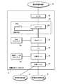
この図1に示すように、本実施形態に係るプラント緊急時情報表示システムは、図16に示す従来のシステムの構成において、発電会社データセンタ(遠隔地の緊急対策拠点)3に、Webサーバ32およびWebクライアント34を追加し、発電所(プラント)1および行政出先機関(遠隔地の緊急対策拠点)7にWebクライアント12,72をそれぞれ追加すると共に、Webサーバ32とWebクライアント12,72間を、通信事業者回線(通信事業用ネットワーク)8を介して接続したものである。さらに、Webサーバ32と通信事業者回線8の間には、発電所1の緊急時に両者を接続する接続手段35が設けられている。 As shown in FIG. 1, the plant emergency information display system according to the present embodiment includes a
発電会社データセンタ3において、収集サーバ31は、Webサーバ32の追加に伴い、監視対象プラントである発電所1の緊急時に、発電所1のプラントデータを、Webサーバ32に対して周期的に送信するように構成されている。また、Webサーバ32は、収集サーバ31から周期的に送信される発電所1のプラントデータを受信し、当該プラントデータを予め設定された表示形式でWeb画面表示する画面表示用画像データを作成し、作成した画面表示用画像データを、通信事業者回線8経由で各Webクライアントに送信して、発電所1のプラントデータをWeb画面表示させるように構成されている。 In the power generation
なお、Webサーバ32は、収集サーバ31と同様に、一般的に「サーバ」と呼ばれる記憶容量の大きなコンピュータから構成されており、Webサーバとしての機能は、一般的に使用されている各種のWebサーバ用ソフトウェアにより容易に実現される。Webクライアント12,34,72は、具体的には、汎用のパーソナルコンピュータから構成されており、Webサーバ32から受信した画面表示用画像データをWeb画面表示させる機能は、一般的に使用されている各種のWebブラウザにより容易に実現される。 Note that, like the
また、本明細書中において、「プラントデータ」は、プロセスデータを各プラントのデータという観点から把握した場合の、プラント単位のプロセスデータを包括的に示す用語である。 Further, in this specification, “plant data” is a term that comprehensively indicates process data for each plant when the process data is grasped from the viewpoint of data of each plant.
[発電会社データセンタの構成]
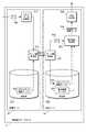
図2は、図1に示すプラント緊急時情報表示システムのうち、発電会社データセンタ3の機器構成を示すブロック図である。[Configuration of power generation company data center]
FIG. 2 is a block diagram showing a device configuration of the power generation
この図2に示すように、発電会社データセンタ3において、収集サーバ31とWebサーバ32は、ハブ36を介して接続され、伝送を行う。このうち、収集サーバ31は、通信ユニット37を介して発電会社専用回線2および通信事業者回線4に接続されている。また、Webサーバ32は、L2スイッチ351とスイッチ352から構成される接続手段35、およびルータ38を介して、通信事業者回線8と接続される。 As shown in FIG. 2, in the power generation
[システム動作]
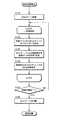
図3は、以上のような構成を有する本実施形態におけるプラント緊急時情報表示システムの動作として、特に、発電会社データセンタ3を中心とした動作の概略を示すフローチャートである。以下には、この図3を参照しながら、本システムの動作について説明する。[System operation]
FIG. 3 is a flowchart showing an outline of an operation centered on the power generation
まず、本システムにおいて、Webサーバ32とWebクライアントとの間の接続は、発電所1の災害時等の緊急時のみ接続できれば十分機能を果たすことができるため、発電会社データセンタ3のWebサーバ32と、発電所1や行政出先機関7のWebクライアント12,72との間の接続は、セキュリティの観点から、Webサーバ32と通信事業者回線8との接続手段35のL2スイッチ(レイヤ2スイッチングハブ)351とスイッチ352により、接続が必要な緊急時にのみ接続する。 First, in this system, since the connection between the
このような、緊急時のみの接続は、L2スイッチ351のバーチャルLAN機能により容易に実現することができる。すなわち、一般に、L2スイッチ351は、LANの物理的な接続形態とは独立に、端末の仮想的なグループを設定する技術であるバーチャルLAN機能を持つことができる。 Such an emergency connection can be easily realized by the virtual LAN function of the
したがって、図1のシステムにおいて、通常時は、接続手段35のL2スイッチ351に接続されているWebサーバ32とルータ38を、別のバーチャルLANグループとして管理し、これらのバーチャルLANグループ間を接続するスイッチ352の回路を開にすることにより、Webサーバ32とルータ38を切り離すことができる。 Therefore, in the system of FIG. 1, normally, the
これにより、通常時において、Webサーバ32と通信事業者回線8は切り離されており、Webサーバ32から発電所1や行政出先機関7のWebクライアント12,72に対して画面表示用画像データが送信されることはなく、それらのWebクライアント12,72上に、発電所1のプラントデータがWeb画面表示されることはない。 As a result, the
一方、図3に示すように、発電所1の災害時等において、プラント情報の表示が必要な緊急状態発生時には、Webサーバ32とルータ38という2つのバーチャルLANグループを接続するスイッチ352の回路を閉にすることにより、Webサーバ32とルータ38が接続され、Webサーバ32と通信事業者回線8が接続される(S110)。 On the other hand, as shown in FIG. 3, in the event of a disaster in the
これにより、図3に示すような収集サーバ31とWebサーバ32による周期的なループ処理(LOOP)が可能となる。すなわち、発電所1の緊急時には、予め設定された周期の各期毎に、収集サーバ31からWebサーバ32に対して発電所1のプラントデータが送信される(S120)。Webサーバ32により、当該プラントデータを予め設定された表示形式でWeb画面表示する画面表示用画像データが作成され、ルータ38および通信事業者回線8経由で発電所1や行政出先機関7の各Webクライアント12,72に送信される(S130)。 Thereby, a periodic loop process (LOOP) by the
発電所1や行政出先機関7の各Webクライアント12,72により、Webサーバ32からの画面表示用画像データが受信されると、それらのWebクライアント12,72上には、発電所1のプラントデータが、予め設定された同じ表示形式でWeb画面表示される(S140)。なお、発電会社データセンタ3内のWebクライアント34は、Webサーバ32からの画面表示用画像データを直接受け取り、このWebクライアント34上にも、他のWebクライアント12,72上と同じプラントデータが、同じ表示形式でWeb画面表示される。 When image data for screen display is received from the
以上のような周期的なループ処理(LOOP)は、発電所1の緊急状態が継続する間(S150のYES)は周期的に繰り返される。そして、各Webクライアント12,34,72上に表示される同じプラント情報に基づき緊急対策が行われて、緊急状態が終了した時点で(S150のNO)、接続手段35のスイッチ352の回路を開にすることにより、Webサーバ32とルータ38が切り離され、Webサーバ32と通信事業者回線8が切り離されて(S160)、通常状態となる。 The periodic loop process (LOOP) as described above is periodically repeated while the emergency state of the
[基本的な効果]
以上のようなシステム構成を持ち、システム動作を行う本実施形態のシステムによれば、次のような効果が得られる。[Basic effects]
According to the system of this embodiment having the system configuration as described above and performing the system operation, the following effects can be obtained.
まず、監視対象プラントである発電所1の緊急時に、収集されたプラントデータを収集サーバ31によりそのまま送信するのではなく、収集サーバ31と協働するWebサーバ32により、当該プラントのプラントデータを特定の表示形式で画面表示するための画面表示用画像データを作成し、発電会社データセンタ3内のWebクライアント34に送信すると共に通信事業者回線8経由で発電所1や行政出先機関7の各Webクライアント12,72に送信することができる。 First, the collected plant data is not transmitted as it is by the
したがって、行政出先機関7、発電会社データセンタ3、および発電所1内にそれぞれ設けられた全ての緊急対策拠点に対して、同一のプラントデータを示す同一の画面表示用画像データを送信することができるため、それらの全ての緊急対策拠点でプラント情報を同一の表示形式で同時に表示可能であり、発電所緊急時の情報共有に貢献できる。 Therefore, it is possible to transmit the same screen display image data indicating the same plant data to all the emergency countermeasure bases provided in the
[サーバ構成と処理内容の具体例]
以下には、発電会社データセンタ3における収集サーバ31とWebサーバ32の構成とデータ処理内容の具体例について説明する。[Specific examples of server configuration and processing contents]
Below, the structure of the
[リアルタイム表示用の具体例]
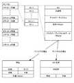
図4は、収集サーバ31とWebサーバ32の構成の一例として、リアルタイム表示を行うサーバ構成例を示すブロック図である。この図4に示すように、収集サーバ31は、サーバ間伝送部311、記憶部312、プラントデータ収集部313、を備えている。また、Webサーバ32は、サーバ間伝送部321、記憶部322、表示画面作成部323、外部伝送部324、を備えている。[Specific examples for real-time display]
FIG. 4 is a block diagram illustrating an example of a server configuration that performs real-time display as an example of the configuration of the
ここで、収集サーバ31の記憶部312には、プラントデータを定義するプラントデータ情報テーブル101が保存されている。また、プラントデータ収集部313は、監視対象プラントである発電所1内のプロセス計算機11から一定の周期で送信されるプラントデータ102を収集する。一方、Webサーバ32の記憶部322には、画面構成について、画面上の表示位置、表示項目、表示形式などを定義する表示情報テーブル103が保存されている。このWebサーバ32の記憶部322にはまた、収集サーバ31からプラントデータ情報テーブル101を受信した場合に、このプラントデータ情報テーブル101が保存されるようになっている。 Here, the
なお、サーバ31,32間でのデータの流れを明確に示す観点から、図4および後述する別のサーバ構成例を示すブロック図(図8、図12)においては、記憶部312,322に予め保存されているデータを実線で示し、受信した時点で新たに保存されるデータを破線で示している。 From the viewpoint of clearly showing the flow of data between the
また、図4および後述する図8、図12においては、図面の簡略化の観点から、収集サーバ31とWebサーバ32の構成のみが示されており、これらのサーバ31,32間のハブ36を初めとして、発電会社データセンタ3内における他の構成の記載は省略されている。 4 and FIGS. 8 and 12, which will be described later, only the configuration of the
図5は、図4のサーバ構成において、サーバ間のデータ伝送手順を示すタイムチャートである。この図5に示すように、緊急状態発生によるシステム起動時において、Webサーバ32が通信事業者回線8と接続されて、Webクライアント12,72への送信が可能となった場合に、Webサーバ32は、収集サーバ31に対して、サーバ間伝送部321によりデータ伝送要求を行う。 FIG. 5 is a time chart showing a data transmission procedure between servers in the server configuration of FIG. As shown in FIG. 5, when the system is started due to the occurrence of an emergency state, when the
収集サーバ31は、サーバ間伝送部311によりWebサーバ32からのデータ伝送要求を受信し、このデータ伝送要求をトリガとして、記憶部312に保存しているプラントデータ情報テーブル101をWebサーバ32に送信する。ここで、プラントデータ情報テーブル101は、具体的には、プラントデータのデータの並び・データ名称・単位等を定義したテーブルであり、予め登録された全ての監視対象プラント(具体的には、対象となる発電会社が持つ全ての発電所)のデータを全て含む。図6は、プラントデータ情報テーブル101の構成例を示すデータ構成図である。 The
図5に示すように、プラントデータ情報テーブル101を受信したWebサーバ32は、このプラントデータ情報テーブル101を記憶部322に保存すると共に、収集サーバ31に対して正常受信応答を行う。Webサーバ32からのこの正常受信応答により、収集サーバ31は、プラントデータ102の定周期送信を開始する。図7は、定周期送信されるプラントデータ102の構成例を示すデータ構成図であり、プラントヘッダ部とn点目のデータ部から構成されている。 As illustrated in FIG. 5, the
Webサーバ32は、サーバ間伝送部311により収集サーバ31から送信されるプラントデータ102の定周期受信を開始すると、受信する各期ごとに、表示画面作成部323により、記憶部322に保存している表示情報テーブル103とプラントデータ情報テーブル101、およびプラントデータ102を用いて画面表示用画像データ104を作成する。すなわち、表示画面作成部323は、表示情報テーブル103を参照し、画面上の表示位置、表示項目、表示形式などを取得すると共に、該当する表示項目を、プラントデータ情報テーブル101および今回受信したプラントデータ102から取得して、このプラントデータ102を所定の表示形式でWeb画面表示する画面表示用画像データ104を作成する。 When the
Webサーバ32は、表示画面作成部323により画面表示用画像データ104を作成した時点で、作成した画面表示用画像データ104を外部伝送部324によりサーバ外部に送信する。すなわち、Webサーバ32においては、収集サーバ31からプラントデータ102を定周期受信する各期ごとに、今回受信した最新のプラントデータ102の画面表示用画像データ104が作成され、作成された画面表示用画像データ104は、発電会社データセンタ3内のWebクライアント34に送信されると共に、ルータ38および通信事業者回線8経由で、発電所1や行政出先機関7の各Webクライアント12,72に送信される。 When the screen
図4のサーバ構成で以上のようなデータ処理を行うことにより、行政出先機関7、発電会社データセンタ3、および発電所1内にそれぞれ設けられた全ての緊急対策拠点に対して、同一のプラントデータ102を示す同一の画面表示用画像データ104を定周期で送信することができるため、それらの全ての緊急対策拠点で同一のプラント情報を同一の表示形式で連続的にリアルタイム表示可能であり、発電所緊急時の情報共有により一層貢献できる。 By performing the above data processing with the server configuration of FIG. 4, the same plant is provided for all emergency countermeasure bases provided in the
特に、図7に示すようなプラントデータに、プラントプロセスの全点のデータ部を含めることにより、全ての緊急対策拠点でプラントプロセスの全点の情報を同一の表示形式で連続的にリアルタイム表示できるため、発電所緊急時の情報共有により一層貢献できる。 In particular, by including the data part of all points of the plant process in the plant data as shown in FIG. 7, the information of all points of the plant process can be continuously displayed in real time in the same display format at all emergency countermeasure bases. Therefore, it is possible to further contribute by sharing information in the event of a power plant emergency.
[グラフ表示用の具体例]
図8は、収集サーバ31とWebサーバ32の構成の一例として、グラフ表示を行うサーバ構成例を示すブロック図である。この図8に示すように、収集サーバ31の記憶部312には、プラントデータ情報テーブル101に加えて、グラフ用収集データを定義するグラフ収集情報テーブル105が保存されると共に、プラントデータ収集部313で定周期受信するプラントデータをグラフ作成用のデータとして複数期にわたって収集したグラフ用収集データ106が保存されている。なお、収集サーバ31の他の部分は、前述した図4の収集サーバ31と同様に構成されている。[Specific example for graph display]
FIG. 8 is a block diagram illustrating a server configuration example that displays a graph as an example of the configuration of the
また、Webサーバ32の記憶部322には、図4の表示情報テーブル103の代わりに、グラフ形式で画面表示を行うための画面構成について、画面上の表示位置、表示項目、表示形式などを定義するグラフ表示情報テーブル103gが保存されている。Webサーバ32にはまた、図4の表示画面作成部323の代わりに、グラフ形式画面表示用画像データ104gを作成するグラフ表示画面作成部323gが設けられている。なお、Webサーバ32の他の部分は、前述した図4のWebサーバ32と同様に構成されている。 In addition, in the
図9は、図8のサーバ構成において、サーバ間のデータ伝送手順を示すタイムチャートである。この図9に示すように、緊急状態発生によるシステム起動時において、Webサーバ32が、収集サーバ31に対して、サーバ間伝送部321によりデータ伝送要求を行うと、収集サーバ31は、このデータ伝送要求をトリガとして、記憶部312に保存しているプラントデータ情報テーブル101、グラフ収集情報テーブル105、およびグラフ収集データ106をWebサーバ32に送信する。ここで、プラントデータ情報テーブル101は、図4のプラントデータ情報テーブル101と同様に、例えば、図6に示すように構成されている。 FIG. 9 is a time chart showing a data transmission procedure between servers in the server configuration of FIG. As shown in FIG. 9, when the
また、グラフ収集情報テーブル105は、発電所1の各発電機「…号機」毎に設定される各グラフに対して、表示するデータ項目の「ID番号」とグラフ表示上の「上限値」と「下限値」を定義したテーブルである。図10は、グラフ収集情報テーブル105の構成例を示すデータ構成図である。 In addition, the graph collection information table 105 includes “ID number” of the data item to be displayed and “upper limit value” on the graph display for each graph set for each generator “... It is a table that defines a “lower limit value”. FIG. 10 is a data configuration diagram illustrating a configuration example of the graph collection information table 105.
また、グラフ用収集データ106は、収集サーバ31がプロセス計算機11より常時受信しているプラントデータをグラフ作成用のデータとして収集している保存ファイルである。図11は、グラフ用収集データ106の構成例を示すデータ構成図である。 The
図9に示すように、プラントデータ情報テーブル101、グラフ収集情報テーブル105、およびグラフ収集データ106を受信したWebサーバ32は、これらのデータを記憶部322に保存すると共に、収集サーバ31に対して正常受信応答を行う。Webサーバ32からのこの正常受信応答により、収集サーバ31は、プラントデータ102の定周期送信を開始する。ここで、プラントデータ102は、図4のプラントデータ102と同様に、例えば、図7に示すように構成されている。 As illustrated in FIG. 9, the
Webサーバ32は、収集サーバ31から、プラントデータ情報テーブル101、グラフ収集情報テーブル105、およびグラフ収集データ106を受信した時点で、グラフ表示画面作成部323gにより、これらのデータ101,105,106と、記憶部322に予め保存されているグラフ表示情報テーブル103gを用いて、グラフ形式画面表示用画像データ104gを作成する。 When the
すなわち、グラフ表示画面作成部323gは、定周期受信された複数期のプラントデータであるグラフ収集データ106を所定のグラフ表示形式でWeb画面表示するグラフ形式画面表示用画像データ104gを作成する。Webサーバ32は、作成したグラフ形式画面表示用画像データ104gを、外部伝送部324によりサーバ外部に送信する。すなわち、グラフ画面表示用画像データ104gは、図4の画面表示用画像データ104gと同様に、発電会社データセンタ3内のWebクライアント34に送信されると共に、ルータ38および通信事業者回線8経由で、発電所1や行政出先機関7の各Webクライアント12,72に送信される。 That is, the graph display
また、Webサーバ32は、収集サーバ31から送信されるプラントデータ102の定周期受信を開始すると、このプラントデータ102を定周期受信する各期ごとに、今回受信した最新のプラントデータ102をグラフ用収集データ106に追加する形で保存し、グラフ用収集データ106を更新すると共に、更新したグラフ用収集データ106を所定のグラフ表示形式でWeb画面表示するグラフ形式画面表示用画像データ104gを作成し、サーバ外部の各Webクライアント12,34,72に送信する。 In addition, when the
図8のサーバ構成で以上のようなデータ処理を行うことにより、行政出先機関7、発電会社データセンタ3、および発電所1内にそれぞれ設けられた全ての緊急対策拠点に対して、複数期にわたる同一のプラントデータ102をグラフ形式で示す同一のグラフ形式画面表示用画像データ104gを定周期で送信することができるため、それらの全ての緊急対策拠点で連続的な同一のプラント情報を同一のグラフ形式でリアルタイム更新しながらリアルタイム表示可能であり、発電所緊急時の情報共有により一層貢献できる。 By performing the data processing as described above with the server configuration of FIG. 8, it is possible to cover a plurality of periods with respect to all emergency countermeasure bases provided in the
特に、緊急状態発生時であるシステム起動時において、それ以前に収集された複数期にわたる過去のプラント情報をグラフ表示できるため、発電所緊急時の情報共有により一層貢献できる。また、収集サーバ31とWebサーバ32の両方で、複数期にわたる同一のプラントデータ102を共有できるため、各Webクライアント12,34,72だけでなく、発電会社データセンタ3内の収集サーバ用クライアント33でも、連続的な同一のプラント情報を同一のグラフ形式でリアルタイム更新しながらリアルタイム表示可能であり、この点からも、発電所緊急時の情報共有により一層貢献できる。 In particular, at the time of system start-up when an emergency situation occurs, past plant information collected over a plurality of periods collected before that time can be displayed in a graph, so that it is possible to further contribute to information sharing during power plant emergencies. Further, since both the
[ユーザ認証用の具体例]
図12は、収集サーバ31とWebサーバ32の構成の一例として、ユーザ認証を行うサーバ構成例を示すブロック図である。この図12に示すように、収集サーバ31には、図4の収集サーバ31の構成に、ユーザレベル確認部314およびユーザレベル記憶部315が追加されており、ユーザレベル記憶部315には、各ユーザのユーザレベル(システム内のデータに対するユーザのアクセスレベル)を、ユーザIDおよびパスワードと対応付けて定義するユーザレベルテーブル107が保存されている。なお、収集サーバ31の他の部分は、前述した図4の収集サーバ31と同様に構成されている。[Specific example for user authentication]
FIG. 12 is a block diagram illustrating a server configuration example for performing user authentication as an example of the configuration of the
また、Webサーバ32には、図4のWebサーバ32の構成に、ユーザ認証部325およびユーザ認証情報記憶部326が追加されており、ユーザ認証情報記憶部326には、ログイン中のユーザのユーザレベルを管理するログインユーザ管理テーブル108および各ユーザレベルに対応する表示画面の種別を定義する閲覧許可テーブル109が保存されている。なお、Webサーバ32の他の部分は、前述した図4のWebサーバ32と同様に構成されている。 Further, in the
図13は、図12のサーバ構成において、サーバ間のユーザ認証時におけるデータ伝送手順を示すタイムチャートである。この図13に示すように、いずれかのWebクライアント12,34,72のユーザから、Webサーバ32に対して、外部伝送部324によりユーザIDとパスワードを含むログイン要求がなされた場合に、Webサーバ32のユーザ認証部325は、サーバ間伝送部321を通じて、ログイン要求のユーザIDとパスワードを収集サーバ31に送信する。 FIG. 13 is a time chart showing a data transmission procedure at the time of user authentication between servers in the server configuration of FIG. As shown in FIG. 13, when a user of any of the
収集サーバ31のユーザレベル確認部314は、サーバ間伝送部311を通じて、Webサーバ32からのユーザIDとパスワードを受け取り、ユーザレベル記憶部315のユーザレベルテーブル107を参照して、ユーザIDとパスワードが適合していることを確認し、ログイン要求元のユーザが所属するユーザレベル107nをWebサーバ32に返信する。 The user
Webサーバ32のユーザ認証部325は、収集サーバ31からログイン要求元のユーザのユーザレベル107nを受け取ると、当該ユーザのユーザIDとユーザレベル107nを、当該ユーザがログアウトするまでの間、ユーザ認証情報記憶部326のログインユーザ管理テーブル108に一時的に保存すると同時に、当該ユーザのWebクライアントに対してログイン応答としての成功画面を返す。図14は、ログインユーザ管理テーブル108の構成例を示すデータ構成図である。 When the
ログインに成功した後、当該ログインユーザからプラント情報の表示要求がなされると、Webサーバ32の表示画面作成部323は、ユーザ認証情報記憶部326のログインユーザ管理テーブル108および閲覧許可テーブル109を参照して、当該ログインユーザのユーザレベル107nにおいてアクセス可能なプラント情報の種別のみをメニューにしたメニュー画面をWeb画面表示するメニュー画面表示用画像データ104mを作成し、当該ログインユーザのWebクライアントに返信する。図15は、閲覧許可テーブル109の構成例を示すデータ構成図であり、この例においては、個々のユーザレベルに対して、表示するプラント情報の種別の異なる複数種類の画面に対するアクセスの可否が対応付けられている。 After the login is successful, when the login user makes a display request for plant information, the display
当該ログインユーザからメニュー画面上で選択された種別のプラント情報の表示要求がなされると、Webサーバ32の表示画面作成部323は、当該種別のプラント情報をWeb画面表示する画面表示用画像データ104をリアルタイム作成し、当該ログインユーザのWebクライアントに送信する。これにより、ログインユーザのWebクライアントにおいては、当該種別のプラント情報のリアルタイム表示が可能になる。 When the logged-in user makes a display request for the type of plant information selected on the menu screen, the display
なお、プラント情報のリアルタイム表示の手法については、図4の構成について前述した手法をそのまま使用できるため、ここでは説明を省略する。 In addition, about the method of the real-time display of plant information, since the method mentioned above about the structure of FIG. 4 can be used as it is, description is abbreviate | omitted here.
図12のサーバ構成で以上のようなデータ処理を行うことにより、システムにユーザ認証機能を持たせることができるため、プラント情報の種別に応じた適切な情報保護を実現しながら、プラント情報を広く開示することができ、緊急時におけるより幅広い情報共有が可能となる。 By performing the data processing as described above with the server configuration of FIG. 12, the system can be provided with a user authentication function. Therefore, while realizing appropriate information protection according to the type of plant information, It can be disclosed, and a wider range of information can be shared in an emergency.
[他の実施形態]
なお、本発明は、前述した実施形態に限定されるものではなく、本発明の範囲内で他にも多種多様な変形例が実施可能である。例えば、前述したグラフ表示用の具体例とユーザ認証用の具体例を組み合わせることなどが可能である。[Other Embodiments]
It should be noted that the present invention is not limited to the above-described embodiments, and various other variations can be implemented within the scope of the present invention. For example, it is possible to combine the above-described specific example for graph display and the specific example for user authentication.
また、前記実施形態で示したプラント緊急時情報表示システムとそれを構成する発電会社データセンタ、収集サーバ、Webサーバ等の具体的な構成やデータ形式、処理手順、処理内容等は、一例にすぎず、収集されたプロセスデータを特定の表示形式でWeb画面表示する画像データを作成し、作成した画像データを、通信事業用ネットワーク経由で複数の緊急対策拠点に送信するものである限り、具体的な構成やデータ形式、処理手順、処理内容等は自由に変更可能である。 Further, the specific configuration, data format, processing procedure, processing content, etc. of the plant emergency information display system and the power generation company data center, collection server, Web server, etc., which are shown in the above embodiment, are only examples. As long as it is possible to create image data that displays the collected process data on a Web screen in a specific display format, and send the created image data to multiple emergency countermeasure bases via a communication business network Various configurations, data formats, processing procedures, processing contents, and the like can be freely changed.
なお、前述した通り、本発明は、原子力発電所等の発電所の緊急時における情報表示システムとして最適であるが、他にも、化学プラント等の緊急時における情報表示が必要な各種の産業プラントに同様に適用可能であり、同様に優れた効果が得られるものである。 As described above, the present invention is optimal as an information display system in an emergency of a power plant such as a nuclear power plant, but in addition, various industrial plants that require information display in an emergency such as a chemical plant. In the same manner, the same effect can be obtained.
1…発電所
11…プロセス計算機
12…(発電所内)Webクライアント
2…発電会社専用回線
3…発電会社データセンタ
31…収集サーバ
311,321…サーバ間伝送部
312,322…記憶部
313…プラントデータ収集部
314…ユーザレベル確認部
315…ユーザレベル記憶部
32…Webサーバ
323…表示画面作成部
323g…グラフ表示画面作成部
324…外部伝送部
325…ユーザ認証部
326…ユーザ認証情報記憶部
33…収集サーバ用クライアント
34…(発電会社データセンタ内)Webクライアント
35…接続手段
351…L2スイッチ
352…スイッチ
36…ハブ
37…通信ユニット
38…ルータ
4,8…通信事業者回線
5…行政データセンタ
51…行政サーバ
6…行政専用回線
7…行政出先機関
71…行政クライアント
72…(行政出先機関内)Webクライアント
101…プラントデータ情報テーブル
102…プラントデータ
103…表示情報テーブル
103g…グラフ表示情報テーブル
104…画面表示用画像データ
104g…グラフ形式画面表示用画像データ
104m…メニュー画面表示用画像データ
105…グラフ収集情報テーブル
106…グラフ用収集データ
107…ユーザレベルテーブル
107n…ユーザレベル
108…ログインユーザ管理テーブル
109…閲覧許可テーブルDESCRIPTION OF
Claims (6)
Translated fromJapanese前記監視対象プラントのプロセスデータを収集する収集サーバと、
前記収集サーバで収集された前記監視対象プラントのプロセスデータを用いて、当該プロセスデータを予め設定された表示形式でWeb画面表示する画面表示用画像データを作成し、作成した画面表示用画像データを、通信事業用ネットワーク経由で、遠隔地および当該監視対象プラント内に設置された複数の緊急対策拠点の各Webクライアントに送信して当該監視対象プラントのプロセスデータをWeb画面表示させるWebサーバと、
前記監視対象プラントの緊急時に前記Webサーバと前記通信事業用ネットワークを接続する接続手段
を備えたことを特徴とするプラント緊急時情報表示システム。In the plant emergency information display system that displays the emergency information of the monitored plant,
A collection server for collecting process data of the monitored plant;
Using the process data of the monitored plant collected by the collection server, screen display image data for displaying the process data on a Web screen in a preset display format is created, and the created screen display image data is A Web server that transmits to the Web clients of a plurality of emergency countermeasure bases installed in a remote place and the monitored plant via a communication business network and displays process data of the monitored plant on a Web screen;
A plant emergency information display system comprising connection means for connecting the Web server and the communication business network in an emergency of the monitored plant.
前記Webサーバは、前記収集サーバから周期的に送信される前記監視対象プラントの各期のプロセスデータを周期的に受信して、各期のプロセスデータをWeb画面表示する画面表示用画像データを作成し、作成した各期の画面表示用画像データを前記通信事業用ネットワーク経由で前記Webクライアントに周期的に送信することにより、当該Webクライアント上で当該監視対象プラントのプロセスデータを周期的にWeb画面表示させるように構成されている
ことを特徴とする請求項1に記載のプラント緊急時情報表示システム。The collection server is configured to periodically transmit process data of the monitored plant to the Web server in an emergency of the monitored plant,
The Web server periodically receives process data of each period of the monitored plant periodically transmitted from the collection server, and creates screen display image data for displaying the process data of each period on the Web screen. By periodically transmitting the created screen display image data for each period to the Web client via the communication business network, the process data of the monitored plant can be periodically displayed on the Web client. The plant emergency information display system according to claim 1, wherein the plant emergency information display system is configured to display the plant emergency information.
前記Webサーバは、前記収集サーバから送信される前記監視対象プラントの複数期のプロセスデータを受信して、複数期のプロセスデータをグラフ表示形式でWeb画面表示する画面表示用画像データを作成し、作成した画面表示用画像データを前記通信事業用ネットワーク経由で前記Webクライアントに送信することにより、当該Webクライアント上で当該監視対象プラントの複数期のプロセスデータをグラフ表示形式でWeb画面表示させるように構成されている
ことを特徴とする請求項1または請求項2に記載のプラント緊急時情報表示システム。The collection server periodically collects process data of the monitored plant, stores process data of multiple periods, and stores process data of multiple periods stored for the monitored plant in an emergency of the monitored plant Are transmitted to the web server in a batch,
The Web server receives process data of a plurality of periods of the monitoring target plant transmitted from the collection server, and creates screen display image data for displaying the process data of a plurality of periods in a graph display format on a Web screen, By transmitting the created screen display image data to the Web client via the communication business network, the process data of the plurality of periods of the monitored plant is displayed on the Web client in a graph display format on the Web client. It is comprised, The plant emergency information display system of Claim 1 or Claim 2 characterized by the above-mentioned.
ことを特徴とする請求項1乃至請求項3のいずれかに記載のプラント緊急時情報表示システム。When the web server receives a login request including user identification information from the web client, the web server performs user authentication processing based on the user identification information and displays information corresponding to the user authentication processing result on the web screen The display image data is created, and the created screen display image data is transmitted to the requesting Web client as a login response. The plant emergency information display system described.
収集サーバにより、前記監視対象プラントのプロセスデータを収集するステップと、
Webサーバにより、前記データ収集ステップで収集された前記監視対象プラントのプロセスデータを用いて、当該プロセスデータを予め設定された表示形式でWeb画面表示する画面表示用画像データを作成し、作成した画面表示用画像データを、通信事業用ネットワーク経由で、遠隔地および当該監視対象プラント内に設置された複数の緊急対策拠点の各Webクライアントに送信して当該監視対象プラントのプロセスデータをWeb画面表示させるステップと、
接続手段により、前記監視対象プラントの緊急時に前記Webサーバと前記通信事業用ネットワークを接続するステップ
を含むことを特徴とするプラント緊急時情報表示方法。In the plant emergency information display method for displaying the emergency information of the monitored plant,
Collecting process data of the monitored plant by a collection server;
Using the process data of the monitored plant collected in the data collection step by the Web server, screen display image data for displaying the process data in a Web screen in a preset display format is created, and the created screen The display image data is transmitted to each Web client at a remote location and a plurality of emergency countermeasure bases installed in the monitored plant via the communication business network, and the process data of the monitored plant is displayed on the Web screen. Steps,
A plant emergency information display method comprising a step of connecting the Web server and the communication business network in an emergency of the monitored plant by a connection means.
前記収集サーバで収集された前記監視対象プラントのプロセスデータを用いて、当該プロセスデータを予め設定された表示形式でWeb画面表示する画面表示用画像データを作成する画像データ作成手段と、
前記画像データ作成手段で作成された前記監視対象プラントのプロセスデータの画面表示用画像データを、通信事業用ネットワーク経由で、遠隔地および当該監視対象プラント内に設置された複数の緊急対策拠点の各Webクライアントに送信して当該監視対象プラントのプロセスデータをWeb画面表示させる画像データ送信手段
を備えたことを特徴とするプラント緊急時情報表示用Webサーバ。In cooperation with the collection server that collects the process data of the monitored plant, in the Web server for plant emergency information display that displays the emergency information of the monitored plant,
Using the process data of the monitored plant collected by the collection server, image data creating means for creating image data for screen display for displaying the process data in a Web screen in a preset display format;
The image data for screen display of the process data of the monitoring target plant created by the image data creation means is connected to each of a plurality of emergency countermeasure bases installed in a remote place and the monitoring target plant via a communication business network. A plant emergency information display Web server comprising image data transmission means for transmitting to a Web client and displaying the process data of the monitored plant on a Web screen.
Priority Applications (1)
| Application Number | Priority Date | Filing Date | Title |
|---|---|---|---|
| JP2005033584AJP2006221376A (en) | 2005-02-09 | 2005-02-09 | Plant emergency information display system and method, Web server |
Applications Claiming Priority (1)
| Application Number | Priority Date | Filing Date | Title |
|---|---|---|---|
| JP2005033584AJP2006221376A (en) | 2005-02-09 | 2005-02-09 | Plant emergency information display system and method, Web server |
Publications (1)
| Publication Number | Publication Date |
|---|---|
| JP2006221376Atrue JP2006221376A (en) | 2006-08-24 |
Family
ID=36983677
Family Applications (1)
| Application Number | Title | Priority Date | Filing Date |
|---|---|---|---|
| JP2005033584APendingJP2006221376A (en) | 2005-02-09 | 2005-02-09 | Plant emergency information display system and method, Web server |
Country Status (1)
| Country | Link |
|---|---|
| JP (1) | JP2006221376A (en) |
Cited By (24)
| Publication number | Priority date | Publication date | Assignee | Title |
|---|---|---|---|---|
| JP2010015391A (en)* | 2008-07-03 | 2010-01-21 | Secom Co Ltd | Building management system |
| JP2010146195A (en)* | 2008-12-17 | 2010-07-01 | Mitsubishi Electric Corp | Programmable controller |
| JP2014149703A (en)* | 2013-02-01 | 2014-08-21 | Mitsubishi Electric Corp | Monitoring control system |
| JP2014206470A (en)* | 2013-04-12 | 2014-10-30 | 株式会社東芝 | Nuclear power plant operation system and operation method thereof |
| GB2513708A (en)* | 2013-03-15 | 2014-11-05 | Fisher Rosemount Systems Inc | Method and apparatus for seamless state transfer between user interface devices in a mobile control room |
| CN104392387A (en)* | 2014-10-10 | 2015-03-04 | 华电电力科学研究院 | Unity3D-based circular coal yard three-dimensional (3D) intelligent visualization display platform |
| WO2015102061A1 (en)* | 2014-01-06 | 2015-07-09 | 三菱重工業株式会社 | Emergency decision-making assistance system |
| US9397836B2 (en) | 2014-08-11 | 2016-07-19 | Fisher-Rosemount Systems, Inc. | Securing devices to process control systems |
| US9541905B2 (en) | 2013-03-15 | 2017-01-10 | Fisher-Rosemount Systems, Inc. | Context sensitive mobile control in a process plant |
| US9558220B2 (en) | 2013-03-04 | 2017-01-31 | Fisher-Rosemount Systems, Inc. | Big data in process control systems |
| US9665088B2 (en) | 2014-01-31 | 2017-05-30 | Fisher-Rosemount Systems, Inc. | Managing big data in process control systems |
| US9697170B2 (en) | 2013-03-14 | 2017-07-04 | Fisher-Rosemount Systems, Inc. | Collecting and delivering data to a big data machine in a process control system |
| US9740802B2 (en) | 2013-03-15 | 2017-08-22 | Fisher-Rosemount Systems, Inc. | Data modeling studio |
| US9804588B2 (en) | 2014-03-14 | 2017-10-31 | Fisher-Rosemount Systems, Inc. | Determining associations and alignments of process elements and measurements in a process |
| US9823626B2 (en) | 2014-10-06 | 2017-11-21 | Fisher-Rosemount Systems, Inc. | Regional big data in process control systems |
| US10168691B2 (en) | 2014-10-06 | 2019-01-01 | Fisher-Rosemount Systems, Inc. | Data pipeline for process control system analytics |
| US10282676B2 (en) | 2014-10-06 | 2019-05-07 | Fisher-Rosemount Systems, Inc. | Automatic signal processing-based learning in a process plant |
| US10386827B2 (en) | 2013-03-04 | 2019-08-20 | Fisher-Rosemount Systems, Inc. | Distributed industrial performance monitoring and analytics platform |
| US10503483B2 (en) | 2016-02-12 | 2019-12-10 | Fisher-Rosemount Systems, Inc. | Rule builder in a process control network |
| US10649424B2 (en) | 2013-03-04 | 2020-05-12 | Fisher-Rosemount Systems, Inc. | Distributed industrial performance monitoring and analytics |
| US10649449B2 (en) | 2013-03-04 | 2020-05-12 | Fisher-Rosemount Systems, Inc. | Distributed industrial performance monitoring and analytics |
| US10678225B2 (en) | 2013-03-04 | 2020-06-09 | Fisher-Rosemount Systems, Inc. | Data analytic services for distributed industrial performance monitoring |
| US10866952B2 (en) | 2013-03-04 | 2020-12-15 | Fisher-Rosemount Systems, Inc. | Source-independent queries in distributed industrial system |
| US10909137B2 (en) | 2014-10-06 | 2021-02-02 | Fisher-Rosemount Systems, Inc. | Streaming data for analytics in process control systems |
- 2005
- 2005-02-09JPJP2005033584Apatent/JP2006221376A/enactivePending
Cited By (51)
| Publication number | Priority date | Publication date | Assignee | Title |
|---|---|---|---|---|
| JP2010015391A (en)* | 2008-07-03 | 2010-01-21 | Secom Co Ltd | Building management system |
| JP2010146195A (en)* | 2008-12-17 | 2010-07-01 | Mitsubishi Electric Corp | Programmable controller |
| JP2014149703A (en)* | 2013-02-01 | 2014-08-21 | Mitsubishi Electric Corp | Monitoring control system |
| US10649449B2 (en) | 2013-03-04 | 2020-05-12 | Fisher-Rosemount Systems, Inc. | Distributed industrial performance monitoring and analytics |
| US10866952B2 (en) | 2013-03-04 | 2020-12-15 | Fisher-Rosemount Systems, Inc. | Source-independent queries in distributed industrial system |
| US10678225B2 (en) | 2013-03-04 | 2020-06-09 | Fisher-Rosemount Systems, Inc. | Data analytic services for distributed industrial performance monitoring |
| US10649424B2 (en) | 2013-03-04 | 2020-05-12 | Fisher-Rosemount Systems, Inc. | Distributed industrial performance monitoring and analytics |
| US10386827B2 (en) | 2013-03-04 | 2019-08-20 | Fisher-Rosemount Systems, Inc. | Distributed industrial performance monitoring and analytics platform |
| US9558220B2 (en) | 2013-03-04 | 2017-01-31 | Fisher-Rosemount Systems, Inc. | Big data in process control systems |
| US11385608B2 (en) | 2013-03-04 | 2022-07-12 | Fisher-Rosemount Systems, Inc. | Big data in process control systems |
| US10037303B2 (en) | 2013-03-14 | 2018-07-31 | Fisher-Rosemount Systems, Inc. | Collecting and delivering data to a big data machine in a process control system |
| US10311015B2 (en) | 2013-03-14 | 2019-06-04 | Fisher-Rosemount Systems, Inc. | Distributed big data in a process control system |
| US10223327B2 (en) | 2013-03-14 | 2019-03-05 | Fisher-Rosemount Systems, Inc. | Collecting and delivering data to a big data machine in a process control system |
| US9697170B2 (en) | 2013-03-14 | 2017-07-04 | Fisher-Rosemount Systems, Inc. | Collecting and delivering data to a big data machine in a process control system |
| US9678484B2 (en) | 2013-03-15 | 2017-06-13 | Fisher-Rosemount Systems, Inc. | Method and apparatus for seamless state transfer between user interface devices in a mobile control room |
| US10691281B2 (en) | 2013-03-15 | 2020-06-23 | Fisher-Rosemount Systems, Inc. | Method and apparatus for controlling a process plant with location aware mobile control devices |
| US9778626B2 (en) | 2013-03-15 | 2017-10-03 | Fisher-Rosemount Systems, Inc. | Mobile control room with real-time environment awareness |
| US11573672B2 (en) | 2013-03-15 | 2023-02-07 | Fisher-Rosemount Systems, Inc. | Method for initiating or resuming a mobile control session in a process plant |
| US11169651B2 (en) | 2013-03-15 | 2021-11-09 | Fisher-Rosemount Systems, Inc. | Method and apparatus for controlling a process plant with location aware mobile devices |
| US11112925B2 (en) | 2013-03-15 | 2021-09-07 | Fisher-Rosemount Systems, Inc. | Supervisor engine for process control |
| US10031490B2 (en) | 2013-03-15 | 2018-07-24 | Fisher-Rosemount Systems, Inc. | Mobile analysis of physical phenomena in a process plant |
| US10031489B2 (en) | 2013-03-15 | 2018-07-24 | Fisher-Rosemount Systems, Inc. | Method and apparatus for seamless state transfer between user interface devices in a mobile control room |
| US9740802B2 (en) | 2013-03-15 | 2017-08-22 | Fisher-Rosemount Systems, Inc. | Data modeling studio |
| US10133243B2 (en) | 2013-03-15 | 2018-11-20 | Fisher-Rosemount Systems, Inc. | Method and apparatus for seamless state transfer between user interface devices in a mobile control room |
| US10152031B2 (en) | 2013-03-15 | 2018-12-11 | Fisher-Rosemount Systems, Inc. | Generating checklists in a process control environment |
| GB2513708A (en)* | 2013-03-15 | 2014-11-05 | Fisher Rosemount Systems Inc | Method and apparatus for seamless state transfer between user interface devices in a mobile control room |
| GB2513708B (en)* | 2013-03-15 | 2020-08-19 | Fisher Rosemount Systems Inc | Method and apparatus for seamless state transfer between user interface devices in a mobile control room |
| US10671028B2 (en) | 2013-03-15 | 2020-06-02 | Fisher-Rosemount Systems, Inc. | Method and apparatus for managing a work flow in a process plant |
| US10649413B2 (en) | 2013-03-15 | 2020-05-12 | Fisher-Rosemount Systems, Inc. | Method for initiating or resuming a mobile control session in a process plant |
| US10296668B2 (en) | 2013-03-15 | 2019-05-21 | Fisher-Rosemount Systems, Inc. | Data modeling studio |
| US10649412B2 (en) | 2013-03-15 | 2020-05-12 | Fisher-Rosemount Systems, Inc. | Method and apparatus for seamless state transfer between user interface devices in a mobile control room |
| US10324423B2 (en) | 2013-03-15 | 2019-06-18 | Fisher-Rosemount Systems, Inc. | Method and apparatus for controlling a process plant with location aware mobile control devices |
| US9541905B2 (en) | 2013-03-15 | 2017-01-10 | Fisher-Rosemount Systems, Inc. | Context sensitive mobile control in a process plant |
| US10551799B2 (en) | 2013-03-15 | 2020-02-04 | Fisher-Rosemount Systems, Inc. | Method and apparatus for determining the position of a mobile control device in a process plant |
| JP2014206470A (en)* | 2013-04-12 | 2014-10-30 | 株式会社東芝 | Nuclear power plant operation system and operation method thereof |
| US10204713B2 (en) | 2014-01-06 | 2019-02-12 | Mitsubishi Heavy Industries, Ltd. | Emergency decision-making assistance system |
| JPWO2015102061A1 (en)* | 2014-01-06 | 2017-03-23 | 三菱重工業株式会社 | Emergency decision support system |
| WO2015102061A1 (en)* | 2014-01-06 | 2015-07-09 | 三菱重工業株式会社 | Emergency decision-making assistance system |
| US10656627B2 (en) | 2014-01-31 | 2020-05-19 | Fisher-Rosemount Systems, Inc. | Managing big data in process control systems |
| US9665088B2 (en) | 2014-01-31 | 2017-05-30 | Fisher-Rosemount Systems, Inc. | Managing big data in process control systems |
| US9804588B2 (en) | 2014-03-14 | 2017-10-31 | Fisher-Rosemount Systems, Inc. | Determining associations and alignments of process elements and measurements in a process |
| US9397836B2 (en) | 2014-08-11 | 2016-07-19 | Fisher-Rosemount Systems, Inc. | Securing devices to process control systems |
| US9772623B2 (en) | 2014-08-11 | 2017-09-26 | Fisher-Rosemount Systems, Inc. | Securing devices to process control systems |
| US10282676B2 (en) | 2014-10-06 | 2019-05-07 | Fisher-Rosemount Systems, Inc. | Automatic signal processing-based learning in a process plant |
| US10168691B2 (en) | 2014-10-06 | 2019-01-01 | Fisher-Rosemount Systems, Inc. | Data pipeline for process control system analytics |
| US10909137B2 (en) | 2014-10-06 | 2021-02-02 | Fisher-Rosemount Systems, Inc. | Streaming data for analytics in process control systems |
| US9823626B2 (en) | 2014-10-06 | 2017-11-21 | Fisher-Rosemount Systems, Inc. | Regional big data in process control systems |
| CN104392387B (en)* | 2014-10-10 | 2017-12-15 | 华电电力科学研究院 | A kind of circular coal yard 3 D intelligent based on Unity3D visualizes platform |
| CN104392387A (en)* | 2014-10-10 | 2015-03-04 | 华电电力科学研究院 | Unity3D-based circular coal yard three-dimensional (3D) intelligent visualization display platform |
| US11886155B2 (en) | 2015-10-09 | 2024-01-30 | Fisher-Rosemount Systems, Inc. | Distributed industrial performance monitoring and analytics |
| US10503483B2 (en) | 2016-02-12 | 2019-12-10 | Fisher-Rosemount Systems, Inc. | Rule builder in a process control network |
Similar Documents
| Publication | Publication Date | Title |
|---|---|---|
| JP2006221376A (en) | Plant emergency information display system and method, Web server | |
| US8271626B2 (en) | Methods for displaying physical network topology and environmental status by location, organization, or responsible party | |
| US7392309B2 (en) | Network appliance management | |
| US7185366B2 (en) | Security administration server and its host server | |
| US9002786B2 (en) | System and method for providing data and application continuity in a computer system | |
| CN101621408B (en) | Method for monitoring events in a communication network | |
| KR101371057B1 (en) | Relay communication system and access management apparatus | |
| JP2004227561A (en) | Interactive bidirectional collaboration in process control plant | |
| JP2004038949A (en) | Communication based on web service for use with process control system | |
| CN100349414C (en) | Remote management system | |
| EP2633664B1 (en) | Method and system for establishing secure authenticated bidirectional server communication | |
| AU2011323987A1 (en) | Methods and systems for providing access to data and measurements in a management system | |
| CN111245656B (en) | Method and system for remote monitoring through mobile equipment | |
| US20180324063A1 (en) | Cloud-based system for device monitoring and control | |
| JP2005165402A (en) | Equipment control device and remote equipment control system | |
| WO2001091350A2 (en) | System and method for performing remote security management of client computer systems | |
| JP2002352361A (en) | Building management method and building management system | |
| US10063664B2 (en) | Network system and control device | |
| JP2000354035A (en) | Non-intrusive monitoring centralized system and method for distributed independent data networks | |
| JP5353714B2 (en) | Server system and its event message transmission method | |
| CN111259383B (en) | A security management center system | |
| WO2002037880A1 (en) | Remote controlling system and method | |
| JPH1055291A (en) | Remote maintenance system | |
| JP2005115716A (en) | Remote control system | |
| JP5233359B2 (en) | Mail transmission / reception program, mail transmission / reception device, and mail transmission / reception system |