JP2006218228A - Battery unit, battery device having the same, medical instrument and endoscope - Google Patents
Battery unit, battery device having the same, medical instrument and endoscopeDownload PDFInfo
- Publication number
- JP2006218228A JP2006218228AJP2005036821AJP2005036821AJP2006218228AJP 2006218228 AJP2006218228 AJP 2006218228AJP 2005036821 AJP2005036821 AJP 2005036821AJP 2005036821 AJP2005036821 AJP 2005036821AJP 2006218228 AJP2006218228 AJP 2006218228A
- Authority
- JP
- Japan
- Prior art keywords
- battery
- heat conduction
- forming
- cooling
- unit
- Prior art date
- Legal status (The legal status is an assumption and is not a legal conclusion. Google has not performed a legal analysis and makes no representation as to the accuracy of the status listed.)
- Pending
Links
Images


Classifications
- Y—GENERAL TAGGING OF NEW TECHNOLOGICAL DEVELOPMENTS; GENERAL TAGGING OF CROSS-SECTIONAL TECHNOLOGIES SPANNING OVER SEVERAL SECTIONS OF THE IPC; TECHNICAL SUBJECTS COVERED BY FORMER USPC CROSS-REFERENCE ART COLLECTIONS [XRACs] AND DIGESTS
- Y02—TECHNOLOGIES OR APPLICATIONS FOR MITIGATION OR ADAPTATION AGAINST CLIMATE CHANGE
- Y02E—REDUCTION OF GREENHOUSE GAS [GHG] EMISSIONS, RELATED TO ENERGY GENERATION, TRANSMISSION OR DISTRIBUTION
- Y02E60/00—Enabling technologies; Technologies with a potential or indirect contribution to GHG emissions mitigation
- Y02E60/10—Energy storage using batteries
Landscapes
- Instruments For Viewing The Inside Of Hollow Bodies (AREA)
- Endoscopes (AREA)
- Secondary Cells (AREA)
- Battery Mounting, Suspending (AREA)
Abstract
Description
Translated fromJapanese本発明は、1次電池または2次電池として使用されるバッテリ手段(以下、単に「バッテリ」という)を有するバッテリユニット、そのバッテリユニットを有するバッテリ装置、医療機器および内視鏡に関し、特に高温状態を含む外部環境にも耐性を有するバッテリユニット、そのバッテリユニットを有するバッテリ装置、医療機器および内視鏡に関するものである。 The present invention relates to a battery unit having battery means (hereinafter simply referred to as a “battery”) used as a primary battery or a secondary battery, a battery device having the battery unit, a medical device, and an endoscope, particularly in a high temperature state. The present invention relates to a battery unit having resistance to an external environment including a battery unit, a battery device having the battery unit, a medical device, and an endoscope.
たとえば、従来の乾電池などのバッテリは、所定の装置に設けられた正極および負極の電極を備えたバッテリ収容ケースに収容されており、これら電極および電極に繋がる導電線などを介して電気的に接続された所定の機能を実行する機能実行手段としての負荷装置や回路に電力を供給することで、この機能実行手段の駆動を可能にしている。 For example, a battery such as a conventional dry battery is housed in a battery housing case provided with a positive electrode and a negative electrode provided in a predetermined device, and is electrically connected via a conductive wire connected to the electrode and the electrode. The function execution means can be driven by supplying power to a load device or a circuit as a function execution means for executing the predetermined function.
ところが、近年では、このような構成のバッテリを高温状態の外部環境下に配置したり、高温状態の外部環境下で使用する状況が発生する場合が考えられる。このような状況としては、バッテリを、たとえば被検体に対する医療行為に使用する際に、滅菌を必要とする場合、高温や低温下での工業用に使用する場合、温度条件の厳しい宇宙環境で使用する場合などが考えられる。このような場合には、一般的に用いられている、たとえば熱伝導性のあるステンレス鋼などの金属やプラスチック材質のバッテリ収容ケースにバッテリを収容する構成では、外部からの熱がバッテリに伝達されてしまって、電池の性能が劣化することがあり、高温状態に対応することが困難であった。たとえば、機能実行装置として特許文献1に示す医療用の内視鏡装置においては、このバッテリ収容ケースを熱伝導性の高い金属やプラスチック材質で構成し、このバッテリ収容ケースにバッテリを収容して、負荷装置であるランプとバッテリを電気的に接続させて、ランプに電力を供給するように構成されている。 However, in recent years, there may be a case where a battery having such a configuration is placed in a high-temperature external environment or used in a high-temperature external environment. Such situations include the use of batteries in space environments where temperature conditions are severe, such as when sterilization is required, for example, when medical treatment is performed on a subject, or when the battery is used for industrial purposes at high or low temperatures. If you want to. In such a case, in a configuration in which the battery is housed in a battery housing case made of metal or plastic material such as stainless steel having thermal conductivity, which is generally used, heat from the outside is transmitted to the battery. As a result, the performance of the battery may deteriorate, and it is difficult to cope with a high temperature state. For example, in the medical endoscope apparatus shown in
この内視鏡装置では、このランプからの出射光をライトガイドファイバなどに導光し、ライト部先端側の照明窓からこの導光された照明光を出射させて、被検者の被検部位である胃、大腸などの臓器の内部(体腔内)を照明し、その反射光を内視鏡装置に取り込むことで、医者もしくは看護士による観察を可能にしていた。 In this endoscope apparatus, the emitted light from the lamp is guided to a light guide fiber or the like, and the guided illumination light is emitted from the illumination window on the front end side of the light unit, so that the test site of the subject is examined. By illuminating the inside of the organ such as the stomach and large intestine (inside the body cavity) and taking the reflected light into the endoscope device, observation by a doctor or a nurse was made possible.
しかしながら、現状の医療においては、たとえば高温度と圧力を加えた加圧水蒸気を生成し、この水蒸気によって、内視鏡装置を蒸気滅菌(オートクレーブ滅菌)してから、被検者に対して使用する状況が生じる場合がある。このオートクレーブ滅菌では、たとえば135℃に加熱され、かつ2.2気圧に加圧された加圧水蒸気で、内視鏡装置を20分間加熱して滅菌するので、この20分間の加熱の間に加圧水蒸気による熱がバッテリ収容ケースを介してバッテリに伝わり、電池に悪影響を与えて電池の性能を劣化させる場合がある。 However, in the current medical treatment, for example, pressurized water vapor with high temperature and pressure is generated, and the endoscope apparatus is steam sterilized (autoclave sterilization) with this water vapor before being used for the subject. May occur. In this autoclave sterilization, for example, the endoscope apparatus is sterilized by heating with pressurized steam heated to 135 ° C. and pressurized to 2.2 atmospheres for 20 minutes. The heat generated by the heat is transmitted to the battery through the battery housing case, and may adversely affect the battery and degrade the battery performance.
本発明は、上記問題に鑑みてなされたものであって、外部環境が高温状態においてもバッテリの性能を劣化させることなく、この外部環境の高温状態に良好に対応できるバッテリユニット、そのバッテリユニットを有するバッテリ装置、医療機器および内視鏡を提供することにある。 The present invention has been made in view of the above-described problem. A battery unit that can satisfactorily cope with a high temperature state of the external environment without deteriorating the performance of the battery even when the external environment is a high temperature state. An object of the present invention is to provide a battery device, a medical device, and an endoscope.
上述した課題を解決し、目的を達成するために、本発明にかかるバッテリユニットは、外部側から内部側への熱伝導が低減される第1の熱伝導低減領域を形成するための第1の熱伝導低減領域形成手段と、電極部を有し、前記第1の熱伝導低減領域内に設けられるバッテリ手段と、少なくとも前記バッテリ手段を冷却する第1の冷却手段と、前記バッテリ手段から前記第1の冷却手段へ熱を伝導するための第1の熱伝導領域を形成する第1の熱伝導領域形成手段と、を有することを特徴とする。 In order to solve the above-described problems and achieve the object, a battery unit according to the present invention includes a first heat conduction reducing region in which heat conduction from the outside to the inside is reduced. A heat conduction reduction region forming means; a battery means having an electrode portion and provided in the first heat conduction reduction region; a first cooling means for cooling at least the battery means; and And a first heat conduction region forming means for forming a first heat conduction region for conducting heat to one cooling means.
また、請求項2の発明にかかるバッテリ装置は、外部側から内部側への熱伝導が低減される第1の熱伝導低減領域を形成するための第1の熱伝導低減領域形成手段と、電極部を有し、前記第1の熱伝導低減領域内に設けられるバッテリ手段と、少なくとも前記バッテリ手段を冷却する第1の冷却手段と、前記バッテリ手段から前記第1の冷却手段へ熱を伝導するための第1の熱伝導領域を形成する第1の熱伝導領域形成手段と、前記第1の熱伝導低減領域形成手段と前記バッテリ手段と前記第1の冷却手段と前記第1の熱伝導領域形成手段とからなるバッテリユニットを収容可能な収容空間を形成する収容部と、前記収容部の収容空間内に設けられ、外部側から内部側への熱伝導が低減される第2の熱伝導低減領域を形成するための第2の熱伝導低減領域形成手段と、を有することを特徴とする。 According to a second aspect of the present invention, there is provided a battery device comprising: a first heat conduction reduced region forming means for forming a first heat conduction reduced region in which heat conduction from the outside to the inside is reduced; and an electrode A battery means provided in the first heat conduction reduction region, at least a first cooling means for cooling the battery means, and conducting heat from the battery means to the first cooling means. First heat conduction region forming means for forming a first heat conduction region, first heat conduction reduction region forming means, battery means, first cooling means, and first heat conduction region. A housing portion that forms a housing space capable of housing a battery unit comprising the forming means, and a second heat conduction reduction provided in the housing space of the housing portion to reduce heat conduction from the outside to the inside Second heat to form the region Guiding the reduced region forming means, characterized by having a.
また、請求項3の発明にかかる内視鏡は、外部側から内部側への熱伝導が低減される第1の熱伝導低減領域を形成するための第1の熱伝導低減領域形成手段と、電極部を有し、前記第1の熱伝導低減領域内に設けられるバッテリ手段と、少なくとも前記バッテリ手段を冷却する第1の冷却手段と、前記バッテリ手段から前記第1の冷却手段へ熱を伝導するための第1の熱伝導領域を形成する第1の熱伝導領域形成手段と、前記第1の熱伝導低減領域形成手段と前記バッテリ手段と前記第1の冷却手段と前記第1の熱伝導領域形成手段とからなるバッテリユニットを収容可能な収容空間を形成する収容部と、前記収容部の収容空間内に設けられ、外部側から内部側への熱伝導が低減される第2の熱伝導低減領域を形成するための第2の熱伝導低減領域形成手段と、前記収容部と前記第2の熱伝導低減領域形成手段とからなるバッテリ装置と、を有することを特徴とする。 The endoscope according to the invention of
また、請求項4の発明にかかるバッテリ装置は、外部側から内部側への熱伝導が低減される第1の熱伝導低減領域を形成するための第1の熱伝導低減領域形成手段と、電極部を有し、前記第1の熱伝導低減領域内に設けられるバッテリ手段と、前記第1の熱伝導低減領域形成手段と前記バッテリ手段とからなるバッテリユニットを収容可能な収容空間を形成する収容部と、前記収容部の収容空間内に設けられ、外部側から内部側への熱伝導が低減される第2の熱伝導低減領域を形成するための第2の熱伝導低減領域形成手段と、少なくとも前記収容部を冷却する第2の冷却手段と、前記収容部から前記第2の冷却手段へ熱を伝導するための第2の熱伝導領域を形成する第2の熱伝導領域形成手段と、を有することを特徴とする。 According to a fourth aspect of the present invention, there is provided a battery device comprising: a first heat conduction reduced region forming means for forming a first heat conduction reduced region in which heat conduction from the outside to the inside is reduced; and an electrode A battery unit provided in the first heat conduction reduction region, and a housing that forms a housing space capable of housing a battery unit comprising the first heat conduction reduction region forming unit and the battery unit. A second heat conduction reduced region forming means for forming a second heat conduction reduced region provided in the housing space of the housing portion and reduced in heat conduction from the outside side to the inside side; A second cooling means for cooling at least the housing part; a second heat conduction region forming means for forming a second heat conduction area for conducting heat from the housing part to the second cooling means; It is characterized by having.
また、請求項5の発明にかかる内視鏡は、外部側から内部側への熱伝導が低減される第1の熱伝導低減領域を形成するための第1の熱伝導低減領域形成手段と、電極部を有し、前記第1の熱伝導低減領域内に設けられるバッテリ手段と、前記第1の熱伝導低減領域形成手段と前記バッテリ手段とからなるバッテリユニットを収容可能な収容空間を形成する収容部と、前記収容部の収容空間内に設けられ、外部側から内部側への熱伝導が低減される第2の熱伝導低減領域を形成するための第2の熱伝導低減領域形成手段と、少なくとも前記収容部を冷却する第2の冷却手段と、前記収容部から前記第2の冷却手段へ熱を伝導するための第2の熱伝導領域を形成する第2の熱伝導領域形成手段と、前記収容部と前記第2の熱伝導低減領域形成手段と前記第2の冷却手段と前記第2の熱伝導領域形成手段とからなるバッテリ装置と、を有することを特徴とする。 The endoscope according to the invention of
また、請求項6の発明にかかるバッテリ装置は、外部側から内部側への熱伝導が低減される第1の熱伝導低減領域を形成するための第1の熱伝導低減領域形成手段と、電極部を有し、前記第1の熱伝導低減領域内に設けられるバッテリ手段と、少なくとも前記バッテリ手段を冷却する第1の冷却手段と、前記第1の熱伝導低減領域形成手段と前記バッテリ手段と前記第1の冷却手段とからなるバッテリユニットを収容可能な収容空間を形成する収容部と、前記収容部の収容空間内に設けられ、外部側から内部側への熱伝導が低減される第2の熱伝導低減領域を形成するための第2の熱伝導低減領域形成手段と、少なくとも前記収容部を冷却する第2の冷却手段と、前記収容部から前記第2の冷却手段へ熱を伝導するための第2の熱伝導領域を形成する第2の熱伝導領域形成手段と、を有することを特徴とする。 According to a sixth aspect of the present invention, there is provided a battery device comprising: a first heat conduction reduced region forming means for forming a first heat conduction reduced region in which heat conduction from the outside to the inside is reduced; and an electrode Battery means provided in the first heat conduction reduced region, at least first cooling means for cooling the battery means, first heat conduction reduced region forming means, and battery means A housing portion that forms a housing space capable of housing a battery unit comprising the first cooling means, and a second space that is provided in the housing space of the housing portion and reduces heat conduction from the outside to the inside. Heat conduction reduced region forming means for forming the second heat conduction reduced region, second cooling means for cooling at least the accommodating portion, and conduction of heat from the accommodating portion to the second cooling means. A second heat conduction region for A second heat transfer area forming means for forming, characterized by having a.
また、請求項7の発明にかかる内視鏡は、外部側から内部側への熱伝導が低減される第1の熱伝導低減領域を形成するための第1の熱伝導低減領域形成手段と、電極部を有し、前記第1の熱伝導低減領域内に設けられるバッテリ手段と、少なくとも前記バッテリ手段を冷却する第1の冷却手段と、前記第1の熱伝導低減領域形成手段と前記バッテリ手段と前記第1の冷却手段とからなるバッテリユニットを収容可能な収容空間を形成する収容部と、前記収容部の収容空間内に設けられ、外部側から内部側への熱伝導が低減される第2の熱伝導低減領域を形成するための第2の熱伝導低減領域形成手段と、少なくとも前記収容部を冷却する第2の冷却手段と、前記収容部から前記第2の冷却手段へ熱を伝導するための第2の熱伝導領域を形成する第2の熱伝導領域形成手段と、前記収容部と前記第2の熱伝導低減領域形成手段と前記第2の冷却手段と前記第2の熱伝導領域形成手段とからなるバッテリ装置と、を有することを特徴とする。 The endoscope according to the invention of claim 7 includes a first heat conduction reduced region forming means for forming a first heat conduction reduced region in which heat conduction from the outside to the inside is reduced, Battery means having an electrode part and provided in the first heat conduction reduced region, first cooling means for cooling at least the battery means, first heat conduction reduced region forming means, and battery means And a first housing that forms a housing space capable of housing a battery unit comprising the first cooling means and a housing space in the housing portion to reduce heat conduction from the outside to the inside. Heat conduction reduced region forming means for forming the second heat conduction reduced region, second cooling means for cooling at least the accommodating portion, and conducting heat from the accommodating portion to the second cooling means. Forming a second heat conduction region for A battery device comprising: a second heat conduction region forming unit; the housing portion; the second heat conduction reduction region forming unit; the second cooling unit; and the second heat conduction region forming unit. It is characterized by that.
また、請求項8の発明にかかるバッテリユニット、バッテリ装置または内視鏡は、上記発明において、前記第1または第2の冷却手段の作動制御を行う制御手段を、さらに有することを特徴とする。 The battery unit, battery device, or endoscope according to the invention of claim 8 is characterized in that in the above invention, the battery unit, the battery device, or the endoscope further comprises a control means for controlling the operation of the first or second cooling means.
また、請求項9の発明にかかるバッテリユニット、バッテリ装置または内視鏡は、上記発明において、前記バッテリ手段の温度を検出する温度検出手段を、さらに有し、前記制御手段は、前記温度検出手段の検出結果に基づいて、前記第1または第2の冷却手段の作動制御を行うことを特徴とする。 The battery unit, battery device, or endoscope according to the invention of claim 9 further comprises temperature detection means for detecting the temperature of the battery means in the above invention, and the control means is the temperature detection means. Based on the detection result, the operation control of the first or second cooling means is performed.
本発明にかかるバッテリユニットは、バッテリの周囲を熱伝導低減手段で囲繞し、この熱伝導低減手段を介してバッテリと外部に設けられた正極および負極の電極部材を電気的に接続させるとともに、前記バッテリと熱伝導低減手段を収容し、かつ熱伝導領域形成手段を介して、冷却手段によってバッテリ全体を冷却して、バッテリの性能劣化に起因するバッテリの温度を低減させるので、外部環境が高温状態においてもバッテリの性能を劣化させることなく、この外部環境の高温状態に良好に対応できるという効果を奏する。 The battery unit according to the present invention surrounds the periphery of the battery with heat conduction reducing means, and electrically connects the battery and the positive and negative electrode members provided outside through the heat conduction reducing means. The battery and the heat conduction reducing means are accommodated, and the entire battery is cooled by the cooling means via the heat conduction area forming means, so that the temperature of the battery due to the deterioration of the performance of the battery is reduced. In this case, it is possible to satisfactorily cope with the high temperature state of the external environment without degrading the performance of the battery.
以下に、本発明にかかるバッテリユニット、そのバッテリユニットを有するバッテリ装置、医療機器および内視鏡の実施の形態を図1〜図20の図面に基づいて詳細に説明する。なお、本発明は、これらの実施の形態に限定されるものではなく、本発明の要旨を逸脱しない範囲で種々の変更実施の形態が可能である。 Hereinafter, embodiments of a battery unit, a battery device having the battery unit, a medical device, and an endoscope according to the present invention will be described in detail with reference to FIGS. 1 to 20. The present invention is not limited to these embodiments, and various modifications can be made without departing from the scope of the present invention.
(実施の形態1)
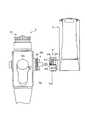
図1は、本発明にかかるバッテリ装置を用いる携帯型内視鏡装置の構成の一例を示す斜視図である。図において、内視鏡装置1は、液体の漏れや透過を防ぐ水密構造の内視鏡2と、この内視鏡2に着脱自在に装着されて電気的に接続されるバッテリ装置3とで構成されている。また、この内視鏡2には、バッテリ装置3の代わりに、図示しないライトガイドケーブルを着脱自在に装着させることも可能である。(Embodiment 1)
FIG. 1 is a perspective view showing an example of the configuration of a portable endoscope apparatus using a battery device according to the present invention. In the figure, an
この内視鏡2は、一端に設けられた接眼部21と、この接眼部21が取り付けられる取り付け側に設けられた操作部22と、この操作部22の他端に設けられ、被検体内に挿入される細長の円筒形状の挿入部23とを有する。この取り付け側の操作部22の側面には、ライトガイド口金22aが突出して設けられており、バッテリ装置3の接続部31が着脱自在に接続される。また、この操作部22の側面には、異なる位置に、挿入部23先端の湾曲動作の操作を行うための湾曲操作レバー22bと、吸引操作を行うための吸引ボタン22cとがそれぞれ突設されている。この吸引ボタン22cの側面には、内視鏡2内に設けられた吸引チャンネル(図示せず)に連通する吸引口金22dが突出しており、たとえばこの吸引口金22dにチューブを取り付け、このチューブを介して所定の吸引装置に接続させ、上述した吸引ボタン22cを適宜操作することで、挿入部23、吸引チャンネルおよび吸引口金22dを介して体腔内の液体などの吸引排出を行うことができる。 The
また、この操作部22には、内視鏡2を保持して固定するために、医者などが把持する把持部22eが設けられている。この操作部22において、挿入部23が取り付けられる取り付け側には、鉗子を挿入するための鉗子挿入口22fが突設されており、この鉗子挿入口22fは、通常鉗子栓22gで閉塞されている。また、鉗子挿入口22fの対向側には、たとえば通気口金22hが設けられ、この通気口金22hから内視鏡2内部に空気を送入することによって、内視鏡2の水漏れ検査を行うことが可能となる。 In addition, the
被検体内に挿入される挿入部23は、先端に設けられた硬質の先端部23aと、操作部22の操作によって湾曲動作を行う湾曲部23bと、柔軟性を有する可撓管23cとを備え、これらの部位は一列に連なるように構成されている。 The
挿入部23内には、バッテリ装置3から出射された照明光を導くためのライトガイドファイバ(図示せず)が内装されている。このライトガイドファイバの一端は、操作部22内部で屈曲され、ライトガイド口金22a内に固定されている。また、このライトガイドファイバの他端は、挿入部23の先端に設けられた照明窓23dに固定されている。したがって、内視鏡装置1は、バッテリ装置3から出射された照明光を、ライトガイド口金22aからライトガイドファイバを通って、照明窓23dから外部に照射でき、これにより挿入された被検体の体腔内を照明することが可能となる。また、ライトガイド口金22aの外周面には、接続用の雄ネジ部22iが設けられている。 A light guide fiber (not shown) for guiding the illumination light emitted from the
図2は、図1に示した操作部22とバッテリ装置3の接続部31の外観を説明するための図である。図1、図2において、バッテリ装置3の接続部31は、外周面に設けられた接続環31aを有し、接続環31aは、内周面に形成されている雌ネジ部31bと、雌ネジ部31bの外周面を被覆するネジカバー31cとを備えている。この接続環31aは、円筒形状の接続口金31dの外周面を囲繞するように設けられ、かつ接続口金31dの長手方向の移動が一定の範囲で移動可能なように規制された状態で、この接続口金31dに取り付けられている。そして、この雌ネジ部31bが、ライトガイド口金22aの外周面に設けられた雄ネジ部22iと螺合するように構成されている。 FIG. 2 is a diagram for explaining the external appearance of the
また、接続口金31dの外周面には、水密リング31eが周設されており、接続部31をライトガイド口金22aに接続させる時に、この水密リング31eがライトガイド口金22aの接続筒22jの内周面に密着している。すなわち、このバッテリ装置3の接続環31aを所定方向に回転させ、ライトガイド口金22aの雄ネジ部22iと接続環31aの雌ネジ部を螺合させることで、内視鏡2のライトガイド口金22aに接続環31aが螺合固定され、かつ接続筒22jと接続口金31dが水密リング31eによって密着されて、内視鏡2とバッテリ装置3が一体に組み合わされることとなる。この構成により、この連結部での水密が確保される。 A
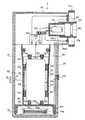
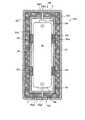
図3は、図1に示したバッテリ装置3の実施の形態1のA−A断面の概略を示す図であり、図4は、同じく実施の形態1のB−B断面の概略を示す図であり、図5は、図1に示したバッテリ装置の接点の一部断面を示す断面図である。これらの図において、バッテリ装置3は、横長の長方体形状の枠体からなるランプを収容するランプ収容部32と、バッテリユニットを収容するバッテリユニット収容手段であり、バッテリユニット収容空間を形成する内面を有する縦長の長方体形状からなる枠体からなるバッテリユニット収容部33とを備える。 FIG. 3 is a diagram showing an outline of the AA cross section of the
バッテリユニット収容部33の内部には、後述するバッテリ34や温度センサ35やペルチェ素子39が接続されたICチップ36を含むバッテリユニット33aのバッテリユニット正電極33p1と接触して電気的に接続される円柱形状の接続端子32eが突起して設けられている。 Inside the battery
ランプ収容部32は、接続端子32eと電気的に接続するとともに、バッテリ手段としてのバッテリ34から接続端子を介して供給される電源をランプ32aに供給して、ランプ32aを点灯させるモード、ランプ32aへの電源供給を遮断することで、ランプを消灯するモード、図示しない電力供給手段から充電用接続端子32fを介してバッテリ34を充電するモード、のモード切換えを行うスイッチ32dと、スイッチ32dがランプ32aを点灯するモードに選択されたときに、ランプ32aに供給する電源電圧をランプ32aの点灯に適切な一定の電圧である駆動電圧に変換する電源回路32cと、バッテリ34から電源電圧の供給を受けて機能する機能実行手段としてのランプ32aと、ランプ32aから出射される照明光を集光する集光レンズ32bと、を収容している。 The
また、ランプ収容部32の枠体には、スイッチ32dおよびバッテリ34に電気的に接続される電力供給手段から充電を行うかもしくは充電チェックを行うための充電用接続端子32fと、内視鏡2との接続時に電気的に導通する接点32gとが、ランプ収容部32の枠体側面を貫通して設けられている。ランプ32aは、スイッチ32dおよび接続端子32eを介して、バッテリユニット33aのバッテリユニット正電極33p1と、また接点32gを介して、バッテリユニット33aのバッテリユニット負電極33q1と接続されている。また、スイッチ32dは、バッテリ装置3の外部から切換え操作が可能なように構成されている。 In addition, the frame of the
接続端子32e,32fおよび接点32gは、少なくとも通常の電気接点として用いられる金属の接点に対しては熱伝導率の低く、かつ導電性のある部材で形成されている。たとえば、これら部材は、シリコンゴム(信越化学工業株式会社製の製品番号がKE3801M−Uのシリコンゴム)などから形成されている。また、接続端子32f及び接点32gは、接続環31a側のランプ収容部32の枠体側面に配置されている。これら部材のうち、充電用接続端子32fは、たとえば外部に設けられたバッテリの充電状態をチェックする充電状態モニタ回路(図示せず)が、接続環31aによってバッテリ装置3に取り付けられた時に、この充電状態モニタ回路とバッテリ34が充電用接続端子32fを介して電気的に接続される。これによって、充電状態モニタ回路がバッテリ34の充電状態をチェックすることが可能となる。 The
また、接点32gは、バッテリ装置3が接続環31aによって、内視鏡2に取り付けられた時に電気的に導通して、バッテリ34からランプ32aへの電源供給を可能にしている。すなわち、図5に示すように、バッテリ装置3の接点32gには、バッテリ34のバッテリ負電極34bと電気的に接続される接点ピン32g1と、接点ピン32g1を付勢させて外部に突出させるスプリング32g2が設けられている。また、このバッテリ装置3の接点32gに対向する内視鏡2の所定位置には、突起22kが設けられており、バッテリ装置3が内視鏡2に取り付けられた時に、図5(a)に示すように、この突起22kが接点32gの接点ピン32g1に当接して、接点ピン32g1をバッテリ装置3内部に押下する。この押下によって、接点ピン32g1とランプ32a側の電路32a1およびバッテリユニット負電極33q1側の電路32a2とが接触して、バッテリ34からランプ32aへの電源供給が可能となる。また、バッテリ装置3が内視鏡2から取り外された時には、図5(b)に示すように、この突起22kと接点32gとの当接が解除され、接点32gが元の位置に戻るので、接点32gとランプ32a側の電路およびバッテリユニット負電極33q1側の電路とが非接触となって、バッテリ34からランプ32aへの電源供給ができなくなる。したがって、この実施の形態では、スイッチ32dがオン状態で、かつバッテリ装置3が内視鏡2に取り付けられた時に、初めてバッテリユニット33aからランプ32aへの電源供給が行われ、このランプ32aから照明光が出射されることとなる。集光レンズ32bは、接続口金31d内に配置され、ランプ32aからの照明光を集光して、内視鏡2内のライトガイドファイバに出射させている。 Further, the
バッテリユニット収容部33は、バッテリ34を含む、たとえば2つの円筒形状のバッテリユニット33aと、このバッテリユニット33aを収容する収容部である内部空間を形成する内面を有する略円筒形状の枠体で構成される収容ケース33bと、収容ケース33bの内面に突起して設けられて、バッテリユニット33aに設けられたバッテリユニット正電極33p1が接続端子32eと接触する内部空間の所定の位置に、バッテリユニット33aを支持して固定する支持手段としての複数のリブ33cと、バッテリユニット33aに設けられたバッテリユニット負電極33q1と接続される接続端子33dと、バッテリユニット収容部33の外表面に設けられ、接点32gと接続端子33dとの電路間に接続される温度スイッチ33eとを備える。なお、収容ケース33bも、熱伝導率の低い部材で構成すれば、本発明にかかる熱伝導低減手段の機能を有することになる。 The battery
リブ33cは、支持手段としての機能を有し、かつバッテリユニット33aおよび収容ケース33bとともに、バッテリユニット33aの外面と収容ケース33bとの間に熱伝導低減手段である空気層33fを形成する空間形成手段としての機能も有する。この空気層33fは、円筒形状のバッテリユニット33aを囲繞するように、設けられており、バッテリ装置3の外部から収容ケース33bを介してバッテリユニット33aに熱が伝導することを防いでいる。 The
また、リブ33cは、形状が略半円柱形状で、熱伝導率の低い部材で構成されており、収容ケース33bからリブ33cを介してバッテリユニット33aに熱が伝導することを防いでいる。したがって、リブ33cは、この形成された空気層33fとともに、外部からバッテリユニット33aへの熱伝導を低減させている。接続端子33dは、舌片形状の板バネからなっており、一端が後述する隔壁33hに固定され、他端が板バネの付勢力によって、バッテリユニット33aのバッテリユニット負電極33q1と接触が容易なように構成されている。また、温度スイッチ33eは、バッテリユニット収容部33の外表面に配設され、外部温度が所定の温度になると、オン状態になって接点32gと接続端子33dとの間の電路を導通させている。この構成により、バッテリユニット33aからランプ32aへの電路が導通して、バッテリユニット33aからランプ32aへの電源供給が可能となる。 Further, the
また、バッテリユニット収容部33は、バッテリユニット33aの下方に、外部の電源供給装置(図示せず)から発振される給電用信号を電磁誘導によって取り込む給電用コイル33gと、取り込んだ給電用信号から電力を再生し、かつ再生した電力を昇圧してバッテリユニット33aに供給する再生昇圧回路(図示せず)とを備え、この給電用コイル33gおよび再生昇圧回路は、電源供給手段を構成している。給電用コイル33gは、図3に示すように、バッテリユニット33aの下方に配置された、断面がコ字形状で上面が略円形の隔壁33hによって隔てられた、収納部33i内の台座33jに巻回されて設けられており、給電用コイル33gと電気的に接続される再生昇圧回路は、収容ケース33b内に設けられている。なお、隔壁33hは、収容ケース33bの底面を形成している。また、隔壁33hも、熱伝導率の低い部材で形成されれば、構成上なお良い。 In addition, the battery
この構成により、給電用コイル33gによって取り込まれた給電用信号は、再生昇圧回路によって電力として再生され、さらに電位をバッテリユニット33a内のバッテリ34の電位にまで昇圧された後に、バッテリ34に蓄積される。このように、バッテリ装置3は、外部からの電磁誘導によって電源が供給される構成を有する。なお、本発明では、給電は実施の形態に示した電磁誘導方式に限るものではなく、マイクロ波を用いるものでも良い。 With this configuration, the power feeding signal captured by the
さらに、バッテリユニット収容部33および収容ケース33bは、このバッテリユニット収容部33の外面と収容ケース33bの外面との間に熱伝導低減手段である空気層33kを形成する空間形成手段としての機能を有する。この空気層33kは、収容ケース33bを囲繞するように形成されている。この構成により、バッテリ装置3は、二重の空気層33f,33kを有して、外部からバッテリユニット33aへの熱伝導を低減している。なお、この発明では、空気層33kの代わりに、バッテリユニット収容部33と収容ケース33b間に真空層を形成することも可能であり、33fを真空層に形成することも可能である。また収容ケースから突出される長方体形状の複数の仕切壁33lによって、この層を仕切ることも可能であり、この構成によって熱伝導を低減できるとともに、バッテリ装置3の内部強度を高めることができる。 Furthermore, the battery
さらにまた、バッテリユニット収容部33の外面には、図3に示すように、放熱板(放熱フィン)40が設けられており、この放熱フィン40は、熱伝導部材(熱伝導棒)41を介して、後述するバッテリユニット33a内のペルチェ素子39と接続され、ペルチェ素子39から生じた熱を、バッテリ装置3の外部に放熱している。なお、熱伝導棒41は、ユニット収容部33n、収容ケース33bおよびバッテリユニット収容部33を貫通して放熱フィン40と接続されている。 Furthermore, as shown in FIG. 3, a heat radiating plate (heat radiating fin) 40 is provided on the outer surface of the battery
図6は、図3に示したバッテリユニット33aの構成の実施の形態1を示す断面図である。なお、以下の図において、図1〜図5の構成部分と同様の構成部分に関しては、説明の都合上、同一符号を付記するものとする。図6において、たとえば単三型の乾電池からなるバッテリ34を取り囲んでカバーする熱伝導低減手段としての、カバー33mと、バッテリ34の外面とカバー33mの内面との間に、熱伝導低減手段としての空気層33rと、カバー33m内にバッテリ34を支持して固定する支持手段としての略半円柱形状の複数のリブ33sと、このカバー33mが収容されるユニット収容部33nと、本発明にかかる電極部としてのバッテリ34のバッテリ正電極34aおよび本発明にかかる第2の電極部としてのバッテリ負電極34bと接続する電極部材33p,33qとを備える。この電極部材33pは、バッテリユニット33aの外表面に設けられた本発明にかかる電極部材としての、たとえば肉薄の円板形状のバッテリユニット正電極33p1と、このバッテリユニット正電極33p1とバッテリ34のバッテリ正電極34aとを電気的に接続させる導電手段としての、導電線33p2とを備える。また、電極部材33qは、バッテリユニット33aの外表面に設けられた本発明にかかる第2の電極部材としての、たとえば肉薄の円板形状のバッテリユニット負電極33q1と、このバッテリユニット負電極33q1とバッテリ34のバッテリ負電極34bとを電気的に接続させる導電手段としての導電線33q2とを備える。これら電極33p1,33q1とユニット収容部33n間には、リング形状の空隙Cが設けられ、電極33p1,33q1とユニット収容部33nが直接接触して、バッテリ34がショートしないように構成されている。 FIG. 6 is a cross-sectional view showing the first embodiment of the configuration of
なお、ユニット収容部33n内のバッテリ34が配置されている空間は、本発明にかかる熱伝導低減領域を構成し、ユニット収容部33nとカバー33mは、この熱伝導低減領域を形成するための、本発明にかかる熱伝導低減領域形成手段を構成している。また、本発明では、ユニット収容部33nを絶縁体により形成することで、空隙Cを設けないようにしても良い。また、空気層33rは、真空層で形成しても良い。さらに、この実施の形態では、単三型の電池を想定したが、本発明ではこれに限らず、電池の種類はどのようなものを使用しても良い。 In addition, the space in which the
カバー33mは、たとえば熱伝導率の低い材料である発泡スチロールからなる熱伝導低減部材により構成されるので、収容ケース33bからバッテリ34に熱が伝導することを防いでいる。また、カバーの強度が十分に高い場合には、このバッテリユニット33aは、ユニット収容部33nを必ずしも備える必要はない。このような構成により、バッテリユニット33aは、バッテリ34への熱伝導を低減させ、かつバッテリ装置の軽量化を図ることができ、操作者による操作性の向上の一助とすることができる。 Since the
また、図7は、図6に示した作動制御装置の構成を示すブロック図である。図6および図7に示すように、バッテリユニット33aは、バッテリユニット内部の温度変化を測定して、ペルチェ素子39をオン/オフ制御する作動制御装置を備える。この作動制御装置は、バッテリユニット33a内の温度を測定する温度センサ35と、この温度センサ35が電気的に接続されるICチップ36と、ICチップ36に接続されるペルチェ素子39とを有する。 FIG. 7 is a block diagram showing a configuration of the operation control device shown in FIG. As shown in FIGS. 6 and 7, the
温度センサ35は、たとえばバッテリ34の下方で、バッテリユニット33aの底面にあたるカバー33m上に載置されている。そして、温度センサ35は、たとえばオートクレーブなどの外的環境で変化するバッテリユニット33a内の温度を測定している。 The
ICチップ36は、温度センサ35からの温度変化測定に伴う内部温度の変化を検知する温度検知回路37と、温度検知回路37から出力される検知信号に応じて、ペルチェ素子39の作動のオン/オフ制御を行う作動制御回路38とから構成されており、このICチップ36は、たとえばカバー33mの内壁に設けられている。なお、温度検知回路37は、バッテリ34の耐熱温度に基づいて、温度変化の有無の判断基準となる閾値を予め設定している。 The
この実施の形態では、この作動制御装置の電源には、バッテリ34による電源を用いている。作動制御回路38は、検知信号の入力の有無を監視しており、この検知信号の有無に応じて、ペルチェ素子39への電力供給をオン/オフ制御している。すなわち、作動制御回路38は、検知信号が入力しない通常状態では、閾値未満の通常温度と判断して、ペルチェ素子39への電力供給をオフ状態に制御して、バッテリ34の冷却を行わない。また、作動制御回路38は、検知信号が入力する高温状態では、閾値以上の高温状態と判断して、ペルチェ素子39への電力供給をオン状態に制御してペルチェ素子39を作動させ、このペルチェ素子39の冷却作用によって、空気層33rを介してバッテリ34を冷却する。 In this embodiment, the power source of the
ペルチェ素子39は、図6に示すように、バッテリ34を取り囲むように円筒形状に形成され、たとえばカバー33mの内周面に設けられている。このペルチェ素子39の内周面は、バッテリ34を冷却するための冷却面を形成し、外周面は、放熱を行うための放熱面を形成している。この放熱面には、熱伝導棒41が設けられており、バッテリ装置3の外部に設けられた放熱フィン40への熱伝導を可能にしている。なお、放熱フィン40は、バッテリ装置3の外面に複数設けて、放熱効果を高めることも可能である。また、ペルチェ素子39は、上記円筒形状に限らず、たとえば曲面を有する板形状に形成することも可能であり、またバッテリ34に対して複数のペルチェ素子を設けることも可能である。この場合には、複数のペルチェ素子を、たとえばバッテリ34への熱伝導の高い部分の近傍に設けて、バッテリ34の冷却効果を高めることも可能である。 As shown in FIG. 6, the
このように、この実施の形態では、バッテリを熱伝導低減手段であるカバーで囲繞するとともに、バッテリユニットと収容ケースの間に空気層を形成させて、バッテリ装置外部から内部への熱伝導を低減させ、かつ冷却手段であるペルチェ素子を、バッテリとカバーの間に設け、たとえばオートクレーブなどの外部環境の高温時に、ペルチェ素子を作動させてバッテリを積極的に冷却するので、外部環境が高温状態においても、バッテリが高温に晒されることがなくなり、これによってバッテリの性能を劣化させることなく、外部環境の高温状態に良好に対応できる。 As described above, in this embodiment, the battery is surrounded by a cover that is a heat conduction reducing means, and an air layer is formed between the battery unit and the housing case to reduce heat conduction from the outside to the inside of the battery device. And a Peltier element, which is a cooling means, is provided between the battery and the cover, and the battery is actively cooled by operating the Peltier element when the external environment such as an autoclave is at a high temperature. However, the battery is not exposed to a high temperature, and this can satisfactorily cope with the high temperature state of the external environment without deteriorating the performance of the battery.
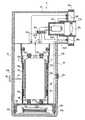
図8は、図1に示したバッテリ装置における実施の形態1の他例のA−A断面の概略構成を示す断面図である。図において、図6に示した上記実施の形態1の構成と異なる点は、収容ケース33bの内周面に、略円筒形状のペルチェ素子39を設けて、ユニット収容部33nを冷却することで、バッテリユニット33a全体を冷却する点である。 FIG. 8 is a cross-sectional view showing a schematic configuration of an AA cross section of another example of the first embodiment in the battery device shown in FIG. 1. In the figure, the difference from the configuration of the first embodiment shown in FIG. 6 is that a substantially
この例の場合には、ペルチェ素子39への電力供給をオン/オフ制御することで、空気層33fを介してユニット収容部33nを冷却するので、バッテリ装置の外部環境が高温状態にあっても、バッテリユニットの外部環境は冷却によって高温状態には至っていないので、外部環境が高温状態においても、間接的にバッテリが高温に晒されることがなくなり、これによってバッテリの性能を劣化させることなく、外部環境の高温状態に良好に対応できる。 In the case of this example, the
なお、本発明では、上記実施の形態の他に、たとえばペルチェ素子39の冷却面を、ユニット収容部33nに当接させて、ユニット収容部33nを直接冷却するように構成することも可能である。この場合には、バッテリユニットの外部が高温状態に晒されても、バッテリユニット自体が直接冷却されるので、外部環境が高温状態においても、間接的にバッテリが高温に晒されることがなくなり、これによってバッテリの性能を劣化させることなく、外部環境の高温状態に良好に対応できる。 In the present invention, in addition to the embodiment described above, for example, the cooling surface of the
また、バッテリ34を冷却するペルチェ素子と、ユニット収容部33nを冷却するペルチェ素子を組み合わせて用いることも無論可能である。この場合には、バッテリ装置内の冷却効果をさらに高めることができる。 It is of course possible to use a combination of a Peltier element that cools the
また、この実施の形態1では、ICチップ36を用いてペルチェ素子39の電力供給のオン/オフ制御を行ったが、本発明はこれに限らず、たとえばペルチェ素子39とバッテリ34を繋ぐ電源線に、磁界の印加によってオン/オフの切り替えを行うリードスイッチを設けることも可能である。すなわち、たとえばオートクレーブの開始直前に、このリードスイッチにバッテリ装置3の外部から磁界を加えることで、リードスイッチをオン動作させて、ペルチェ素子39に電力を供給して冷却を行う。そして、オートクレーブの終了時には、再びリードスイッチに磁界を加えてオフ動作させて、ペルチェ素子の電力供給を断にすることで、ペルチェ素子の電力供給を制御する。この場合には、温度センサやICチップが不要となり、部品点数を削減できるとともに、簡単な構成で外部からペルチェ素子39のオン/オフ動作を制御することができ、これにより上記実施の形態と同様の効果を奏することができる。 In the first embodiment, the on / off control of the power supply of the
(実施の形態2)
図9は、図3に示したバッテリユニットの構成の実施の形態2を示す断面図であり、図10は、図9に示した作動制御装置の構成を示すブロック図である。図において、この実施の形態では、内部に冷却液が循環する液管42を波形状に形成して、カバー33mの内周面に設けるとともに、冷却液を循環制御する冷却ユニット43を、ユニット収容部33nの外周面に設け、かつ液管42の両端部は、カバー33mおよびユニット収容部33nを貫通して、冷却ユニット43の冷却液収納部44に連結されて構成されている。(Embodiment 2)
9 is a cross-sectional view showing a second embodiment of the configuration of the battery unit shown in FIG. 3, and FIG. 10 is a block diagram showing the configuration of the operation control device shown in FIG. In this embodiment, in this embodiment, a
冷却ユニット43は、長方体の枠体45内に密閉構造に形成された領域で、冷却液を収納して液管42との間で冷却液の循環を可能とする冷却液収納部44と、ファン46を回転させることによって冷却液を循環させるモータ47と、枠体45の外面に設けられてバッテリユニット33aの外部温度を測定する温度センサ48と、この温度センサ48が電気的に接続されるICチップ49と、ICチップ49に接続されるペルチェ素子52とを有する。 The cooling
ペルチェ素子52は、循環する冷却液の冷却を行うためのもので、この冷却によって発生した熱を、熱伝導棒41を介して放熱フィン(図示せず)から放熱している。この放熱フィンは、実施の形態1と同様に、バッテリ装置3のバッテリユニット収容部33の外面に設けられ、バッテリ装置3内部で発生した熱をバッテリ装置3の外部に放熱する機能を有している。 The
ICチップ49は、温度センサ48からの温度変化測定に伴うバッテリユニット33aの外部温度の変化を検知する温度検知回路50と、温度検知回路37から出力される検知信号に応じて、モータ47およびペルチェ素子52の作動のオン/オフ制御を行う作動制御回路51とから構成されている。この実施の形態にかかる作動制御回路51も、実施の形態1にかかる作動制御回路38と同様に、モータ47およびペルチェ素子52への電力供給をオン/オフ制御している。すなわち、作動制御回路51は、実施の形態1と同様に、温度検知回路50から検知信号の入力がない通常状態では、モータ47およびペルチェ素子52への電力供給をオフ状態に制御し、冷却液の循環および冷却を停止して、バッテリ34の冷却を行わない。また、作動制御回路51は、検知信号が入力する高温状態では、モータ47およびペルチェ素子52への電力供給をオン状態に制御し、冷却液の循環および冷却を開始して、バッテリ34を冷却させる。 The
このように、この実施の形態では、バッテリの周囲に冷却液を循環させることで、オートクレーブなどの外部環境の高温時に、バッテリを積極的に冷却するので、外部環境が高温状態においても、バッテリが高温に晒されることがなくなり、これによってバッテリの性能を劣化させることなく、外部環境の高温状態に良好に対応できる。 Thus, in this embodiment, the coolant is circulated around the battery to actively cool the battery when the external environment such as the autoclave is at a high temperature. The high temperature state of the external environment can be satisfactorily handled without deteriorating the performance of the battery.
なお、この実施の形態では、液管42を波形状に形成したが、これに限らず、たとえば液管42を、バッテリの正極から負極方向に上記バッテリを取り囲むように、螺旋状に形成させて冷却液を循環させることも可能である。この場合も、実施の形態2と同様の効果を奏することができる。また、ファン46の駆動は、上記モータ47に限らず、たとえばゼンマイなどを駆動源に用いることも可能である。この場合には、バッテリ装置3にオートクレーブを施す時間、ファン46を回転させることができるゼンマイを用いて、液管42内の冷却液を循環させてバッテリ34を冷却させることで、バッテ34の電力消費を低減することが可能となる。 In this embodiment, the
図11は、図1に示したバッテリ装置における実施の形態2のA−A断面の概略構成を示す断面図である。バッテリユニット収容部33の外面に、作動制御装置を有する冷却ユニット43を設けるとともに、液管42の端部と冷却ユニット43との連結をチェッキ弁55やカプラを介して行うことで、液もれを生じることなく冷却ユニット43をバッテリ装置3から着脱可能に構成した。 FIG. 11 is a cross-sectional view showing a schematic configuration of the AA cross section of the battery device shown in FIG. 1 according to the second embodiment. A cooling
また、この実施の形態では、たとえば作動制御装置への電力供給用に1次電池56を用い、かつこの1次電池56も冷却液で冷却可能な構成とした。すなわち、この1次電池56は、図11に示すように、冷却ユニット43内の冷却液とペルチェ素子52とによって冷却が可能になるように、冷却ユニット43内に収納されている。 In this embodiment, for example, the
この実施の形態では、たとえばバッテリ装置3にオートクレーブを施す時には、このバッテリ装置3に冷却ユニット43を取り付けて、バッテリ34の冷却を可能にし、また内視鏡に取り付けて使用する時には、このバッテリ装置から冷却ユニット43を取り外すことができるので、上記実施の形態2と同様の効果を奏するとともに、バッテリの冷却が必要な時にのみ、冷却ユニットを装着でき、バッテリ装置のバッテリの電力消費を低減できるとともに、汎用性に優れたバッテリ装置を提供できる。 In this embodiment, for example, when the autoclave is applied to the
また、バッテリ装置内部に設けられた作動制御装置に外部から電力を供給する場合を、図12および図13に基づいて説明する。なお、図12は、図7に示した作動制御装置に外部から電力を供給する場合の構成を示す図であり、図13は、図12に示した構成の要部を拡大した要部拡大図である。 A case where electric power is supplied from the outside to the operation control device provided inside the battery device will be described with reference to FIGS. 12 and 13. 12 is a diagram showing a configuration in the case where power is supplied from the outside to the operation control device shown in FIG. 7, and FIG. 13 is an enlarged view of a main part in which the main part of the configuration shown in FIG. 12 is enlarged. It is.
図において、バッテリ34の負極方向のバッテリユニット収容部33の底面には、2つの球形で、かつ凹形状に形成された連結部33t,33tが設けられ、かつ外部に開口している。この連結部33t,33tは、導電性の部材から構成され、電源線57,57を介して、作動制御装置のペルチェ素子39などの電力駆動系と接続されている。 In the figure, two spherical and concave connecting
このバッテリ装置3は、オートクレーブを施す際には、オートクレーブ用の袋58に収納された状態で滅菌作業が行われる。このため、この袋58にも、上記連結部33t,33tと同じ形状で、この連結部33t,33tに係合可能な2つの球形で、かつ凹形状に形成された連結部58a,58aが設けられている。この連結部58a,58aも、導電性の部材で構成され、かつ外部に開口している。 When the
また、外部給電用のバッテリボックス59が別体に設けられており、このバッテリボックス59には、上記連結部33t,33t,58a,58aに嵌合可能な2つの球形で、かつ凸形状に形成された連結部59a,59aが設けられている。このバッテリボックス59は、内部に1次電池60を収納しており、この電池60の正極と負極は、導電性の連結部59a,59aと電源線61,61を介して接続されている。 Also, a
このような構成の実施の形態において、バッテリ装置3にオートクレーブを施す際には、まずバッテリ装置3をオートクレーブ用の袋58に収納し、その後にバッテリ装置3の連結部33t,33tと、袋58の連結部58a,58aを係合させる。さらに、この実施の形態では、袋58の外部からバッテリボックス59の連結部59a,59aを、これら連結部33t,33t,58a,58aに嵌合させる。これによって、作動制御装置の電力駆動系と電池60とは、連結部33t,33t,58a,58a,59a,59aおよび電源線57,57,61,61を介して接続されて作動制御装置の電力駆動系に電力が供給されることとなって、バッテリ34の冷却を可能にする。 In the embodiment having such a configuration, when the
このように、この実施の形態では、外部給電用のバッテリボックスをバッテリ装置に接続させて、オートクレーブを施す際に、外部から作動制御装置に電力を供給するので、上記実施の形態2と同様の効果を奏するとともに、バッテリの冷却が必要な時にのみ、別体のバッテリボックスを接続させて、このバッテリボックスから電力を供給することができ、これによりバッテリ装置のバッテリの電力消費を低減できる。 As described above, in this embodiment, when the battery box for external power feeding is connected to the battery device and the autoclave is applied, power is supplied from the outside to the operation control device. In addition to the effects, it is possible to connect a separate battery box and supply power from the battery box only when the battery needs to be cooled, thereby reducing the power consumption of the battery of the battery device.
(実施の形態3)
図14は、図3に示したバッテリユニットの構成の実施の形態3の第1例を示す断面図である。図において、この実施の形態では、バッテリ34を取り囲むように、冷却手段としての冷却剤、たとえばゲル化剤62をカバー33mの内面の全面に設ける。この場合ゲル化剤62は、たとえば収納ケースなどに充填されて、ユニット収容部33n内に設けられている。そして、予めバッテリユニット33aを冷却して、このゲル化剤62を凍らせておき、その状態でバッテリユニット33aを収容するバッテリ装置3にオートクレーブを施す。なお、このゲル化剤62は、たとえばオートクレーブにかかる時間徐々に解けて、ゲル状に変化するように形成されている。(Embodiment 3)
14 is a cross-sectional view showing a first example of
このように、この実施の形態では、バッテリユニット内にゲル化剤を設け、予め凍らせた後にオートクレーブなどによって外部環境を高温状態にするので、バッテリ装置のバッテリを用いずに、バッテリの冷却が可能となり、外部環境が高温状態においても、バッテリが高温に晒されることがなくなり、これによってバッテリの性能を劣化させることなく、外部環境の高温状態に良好に対応できるとともに、バッテリの電力消費を防止することができる。また、この実施の形態では、バッテリユニット内部に冷却用のゲル化剤を設けるという簡単な構成で、かつ繰り返し使用することが可能なので、バッテリ装置の製作コストを削減することもできる。 Thus, in this embodiment, the gelling agent is provided in the battery unit, and after freezing, the external environment is brought to a high temperature state by an autoclave or the like, so that the battery can be cooled without using the battery of the battery device. It is possible to prevent the battery from being exposed to high temperature even when the external environment is hot, which can better cope with the high temperature of the external environment without degrading the battery performance and prevent battery power consumption can do. Further, in this embodiment, since the cooling unit is provided with a simple gelling agent and can be used repeatedly, the manufacturing cost of the battery device can be reduced.
図15は、図3に示したバッテリユニットの構成の実施の形態3の第2例を示す断面図である。図において、この実施の形態では、バッテリ34を取り囲むように半円筒形状に形成された2つのケース63,64が設けられ、そのケース63,64内部には異なる種類の薬液がそれぞれ注入されている。また、各ケース63,64の長手方向の一端は、櫛歯形状の歯部63a,64aが形成されており、この歯部63a,64aは、互いに隙間なく係合している。また、この歯部63a,64aの係合部分には、長手方向の同一位置に孔63b,64bが形成され、この孔63b,64bには円柱形状の仕切棒65が挿入されており、薬液同士が互いに混ざり合うのを防いでいる。 15 is a cross-sectional view showing a second example of the third embodiment of the configuration of the battery unit shown in FIG. In this figure, in this embodiment, two
ケース63,64内に注入された2種類の薬液は、互いに混ざり合うと化学反応を起こして、冷却作用を発生させる。そこで、オートクレーブを施す前に、この仕切棒65を引き抜くと、孔63b,64bが一直線に連なり、この孔63b,64bの部分でケース63,64内部の薬液が混ざり合い、化学反応の発生が可能となる。この化学反応が生じると、冷却作用を発生して近隣のバッテリ34を冷却する。なお、この実施の形態では、仕切棒65を引き抜いた時には、薬液がケース63,64の外部に漏れない構造になっている。 When the two types of chemical solutions injected into the
このように、この実施の形態では、バッテリユニット内に2種類の薬液を注入して設け、オートクレーブ時にこれら薬液を混ざり合わせ、その化学反応でバッテリを冷却するので、図14の実施の形態と同様に、外部環境が高温状態においても、バッテリが高温に晒されることがなくなり、これによってバッテリの性能を劣化させることなく、外部環境の高温状態に良好に対応できるとともに、バッテリの電力消費を防止することができる。また、この実施の形態では、たとえば薬液を交換できる機構を設ければ、繰り返し使用することが可能なので、バッテリ装置の製作コストを削減することもできる。 Thus, in this embodiment, two types of chemical solutions are injected into the battery unit, these chemical solutions are mixed during autoclaving, and the battery is cooled by the chemical reaction. Therefore, as in the embodiment of FIG. In addition, even when the external environment is in a high temperature state, the battery is not exposed to a high temperature, and this can cope with the high temperature state of the external environment without degrading the performance of the battery and also prevent the power consumption of the battery. be able to. Further, in this embodiment, for example, if a mechanism capable of exchanging chemicals is provided, it can be used repeatedly, so that the manufacturing cost of the battery device can be reduced.
また、図16は、図3に示したバッテリユニットの構成の実施の形態3の第3例を示す断面図である。図において、この実施の形態では、バッテリ34を取り囲むように円筒形状に形成された、たとえばセラミック素材からなる液体収容部66を設け、この液体収容部66の内部に、空気に触れると気化する液体、たとえばアルコールなどを注入する。 FIG. 16 is a cross-sectional view showing a third example of the third embodiment of the configuration of the battery unit shown in FIG. In this figure, in this embodiment, a
この液体収容部66には、たとえばカバー33mとユニット収容部33nを貫通して外部に突出する開口部66aが設けられており、通常のバッテリ装置3の使用時などでは、栓などによって開口部66aを閉じている。また、オートクレーブなどの滅菌作業時には、この栓を取り除き、開口部66aを開口状態にすることで、アルコールの気化を促す。アルコールは、気化する際に周囲、この場合にはたとえば液体収容部66などから熱を奪って気化するので、液体収容部66は冷却され、その結果としてバッテリ34が冷却されることとなる。 The
このように、この実施の形態では、液体の気化熱を利用してバッテリを冷却するので、図14の実施の形態と同様に、外部環境が高温状態においても、バッテリが高温に晒されることがなくなり、これによってバッテリの性能を劣化させることなく、外部環境の高温状態に良好に対応できるとともに、バッテリの電力消費を防止することができる。また、この実施の形態では、たとえば液体を開口部から補充することができるので、繰り返し使用することが可能となって、バッテリ装置の製作コストを削減することもできる。 Thus, in this embodiment, the battery is cooled using the heat of vaporization of the liquid, so that the battery may be exposed to a high temperature even when the external environment is at a high temperature as in the embodiment of FIG. As a result, it is possible to satisfactorily cope with the high temperature state of the external environment without deteriorating the performance of the battery, and to prevent battery power consumption. Further, in this embodiment, for example, the liquid can be replenished from the opening, so that it can be used repeatedly, and the manufacturing cost of the battery device can be reduced.
(実施の形態4)
図17は、2次バッテリを内蔵させた実施の形態4における内視鏡の模式図である。この図において、操作部22内には、照明光を導光する導光手段としてのライトガイドファイバ24が挿入されており、このライトガイドファイバ24は、操作部22内で屈曲され、一端が接続ソケット25内で固定される。さらに、接続ソケット25は、内部に照明ランプユニット27と、照明ランプユニット27からの照明光をライトガイドファイバ24の一端面に集光させる集光レンズ26を備える。(Embodiment 4)
FIG. 17 is a schematic diagram of an endoscope according to the fourth embodiment in which a secondary battery is incorporated. In this figure, a
また、接続ソケット25は、バッテリ34のバッテリ正電極34aと電気的に接続されるコイルバネ28と、バッテリ34のバッテリ負電極34bと電気的に接続される接点ピン29と、接点ピン29を付勢させて突出させるスプリング30を備える。また、照明ランプユニット27は、照明光を出射するランプ32aと、ランプ32aを保持するランプホルダ53とを備える。この構成により、照明ランプユニット27が接続ソケット25に差し込まれると、コイルバネ28および接点ピン29が照明ランプユニット27に当接し、バッテリ34とランプ32aが電気的に接続される。そして、ランプ32aから出射された照明光が、集光レンズ26を介してライトガイドファイバ24の光入射端面に供給される。 Further, the
バッテリユニット収容部33は、実施の形態1とほぼ同様の構成からなり、ランプ32aを点灯させるモード、ランプを消灯するモード、内視鏡2の操作部22に設けられた充電用接続端子32fを介してバッテリ34を充電するモード、のモード切換えを行うスイッチ32dと、バッテリ34およびユニット収容部33nを含むバッテリユニット33aと、このバッテリユニット33aを収容する収容部としての収容ケース33bと、収容ケース33b内にバッテリユニット33aを支持して固定する支持手段としての複数のリブ33cと、空気層33fと、バッテリユニット33aの電極部材33p,33qとを備える。また、バッテリユニット収容部33は、バッテリユニット33aの下方に、外部の電源供給装置(図示せず)から発振される給電用信号を電磁誘導によって取り込む給電用コイル33gを備える。 The battery
バッテリユニット33aは、実施の形態1と同様に、バッテリユニット33a内の温度を測定する温度センサ35と、この温度センサ35が電気的に接続されるICチップ36と、ICチップ36に接続されるペルチェ素子39とから構成される作動制御装置を備え、バッテリユニット33a内の温度に応じて、ペルチェ素子39の作動のオン/オフ制御を行っている。 The
また、この実施の形態では、バッテリユニット収容部33の外面に、放熱フィン40が設けられており、この放熱フィン40は、ユニット収容部33n、収容ケース33bおよびバッテリユニット収容部33を貫通する熱伝導棒41を介してペルチェ素子39と接続されている。 Further, in this embodiment, the
このように、この実施の形態では、実施の形態1と同様に、たとえばオートクレーブなどの外部環境の高温時に、バッテリを積極的に冷却するので、外部環境が高温状態においても、バッテリが高温に晒されることがなくなり、これによってバッテリの性能を劣化させることなく、外部環境の高温状態に良好に対応できる。 Thus, in this embodiment, as in the first embodiment, the battery is actively cooled when the external environment such as an autoclave is at a high temperature. Therefore, even when the external environment is at a high temperature, the battery is exposed to a high temperature. Therefore, it is possible to cope with the high temperature state of the external environment without deteriorating the performance of the battery.
(実施の形態5)
図18は、図3に示したバッテリユニットの構成の実施の形態5を示す断面図である。図において、たとえば単三型の乾電池からなるバッテリ34を取り囲んでカバーする熱伝導低減手段としての、カバー33mと、バッテリ34の外面とカバー33mの内面との間に、熱伝導低減手段としての空気層33rと、バッテリ34の外面に当接し、かつバッテリ34を囲繞する熱伝導手段としての円筒形状の熱伝導部材70と、カバー33m内に熱伝導部材70を介在してバッテリ34を支持して固定する支持手段としての略半円柱形状の複数のリブ33sと、このカバー33mが収容されるユニット収容部33nと、本発明にかかる電極部としてのバッテリ34のバッテリ正電極34aおよび本発明にかかる第2の電極部としてのバッテリ負電極34bと接続する電極部材33p,33qとを備える。この電極部材33pは、バッテリユニット33aの外表面に設けられた本発明にかかる電極部材としての、たとえば肉薄の円板形状のバッテリユニット正電極33p1と、このバッテリユニット正電極33p1とバッテリ34のバッテリ正電極34aとを電気的に接続させる導電手段としての、導電線33p2とを備える。また、電極部材33qは、バッテリユニット33aの外表面に設けられた本発明にかかる第2の電極部材としての、たとえば肉薄の円板形状のバッテリユニット負電極33q1と、このバッテリユニット負電極33q1とバッテリ34のバッテリ負電極34bとを電気的に接続させる導電手段としての導電線33q2とを備える。これら電極33p1,33q1とユニット収容部33n間には、リング形状の空隙Cが設けられ、電極33p1,33q1とユニット収容部33nが直接接触して、バッテリ34がショートしないように構成されている。(Embodiment 5)
18 is a cross-sectional view showing a fifth embodiment of the configuration of the battery unit shown in FIG. In the drawing, for example, air as heat conduction reducing means between a
なお、ユニット収容部33n内のバッテリ34が配置されている空間は、本発明にかかる熱伝導低減領域を構成し、ユニット収容部33nとカバー33mは、この熱伝導低減領域を形成するための、本発明にかかる熱伝導低減領域形成手段を構成している。また、本発明では、ユニット収容部33nを絶縁体により形成することで、空隙Cを設けないようにしても良い。また、空気層33rは、真空層で形成しても良い。さらに、この実施の形態では、単三型の電池を想定したが、本発明ではこれに限らず、電池の種類はどのようなものを使用しても良い。 In addition, the space in which the
カバー33mは、たとえば熱伝導率の低い材料である発泡スチロールからなる熱伝導低減部材により構成されるので、収容ケース33bからバッテリ34に熱が伝導することを防いでいる。また、カバーの強度が十分に高い場合には、このバッテリユニット33aは、ユニット収容部33nを必ずしも備える必要はない。このような構成により、バッテリユニット33aは、バッテリ34への熱伝導を低減させ、かつバッテリ装置の軽量化を図ることができ、操作者による操作性の向上の一助とすることができる。 Since the
バッテリユニット33aは、バッテリユニット内部の温度変化を測定して、ペルチェ素子39をオン/オフ制御する作動制御装置を備える。この作動制御装置は、バッテリユニット33a内の温度を測定する温度センサ35と、この温度センサ35が電気的に接続されるICチップ36と、ICチップ36に接続されるペルチェ素子39とを有する。なお、作動制御回路の構成は、図7のブロック図と同様の構成である。 The
すなわち、温度センサ35は、たとえばバッテリ34の下方で、バッテリユニット33aの底面にあたるカバー33m上に載置されている。そして、温度センサ35は、たとえばオートクレーブなどの外的環境で変化するバッテリユニット33a内の温度を測定している。 In other words, the
ICチップ36は、温度センサ35からの温度変化測定に伴う内部温度の変化を検知する温度検知回路37と、温度検知回路37から出力される検知信号に応じて、ペルチェ素子39の作動のオン/オフ制御を行う作動制御回路38とから構成されており、このICチップ36は、たとえばカバー33mの内壁に設けられている。なお、温度検知回路37は、バッテリ34の耐熱温度に基づいて、温度変化の有無の判断基準となる閾値を予め設定している。 The
この実施の形態では、この作動制御装置の電源には、バッテリ34による電源を用いている。作動制御回路38は、検知信号の入力の有無を監視しており、この検知信号の有無に応じて、ペルチェ素子39への電力供給をオン/オフ制御している。すなわち、作動制御回路38は、検知信号が入力しない通常状態では、閾値未満の通常温度と判断して、ペルチェ素子39への電力供給をオフ状態に制御して、バッテリ34の冷却を行わない。また、作動制御回路38は、検知信号が入力する高温状態では、閾値以上の高温状態と判断して、ペルチェ素子39への電力供給をオン状態に制御して、熱伝導部材70を介してバッテリ34全体を直接、かつ積極的に冷却させる。 In this embodiment, the power source of the
ペルチェ素子39は、図18に示すように、バッテリ34を取り囲むように円筒形状に形成され、たとえばカバー33mの内周面に設けられている。このペルチェ素子39の内周面は、バッテリ34を冷却するための冷却面を形成し、外周面は、放熱を行うための放熱面を形成しており、冷却面を熱伝導部材70に当接している。この放熱面には、熱伝導棒41が設けられており、バッテリ装置3の外部に設けられた放熱フィン40への熱伝導を可能にしている。なお、放熱フィン40は、バッテリ装置3の外面に複数設けて、放熱効果を高めることも可能である。また、ペルチェ素子39は、上記円筒形状に限らず、たとえば曲面を有する板形状に形成することも可能であり、またバッテリ34に対して複数のペルチェ素子を設けることも可能である。この場合には、複数のペルチェ素子を、たとえばバッテリへの熱伝導の高い部分の近傍に設けて、バッテリ34の冷却効果を高めることも可能である。 As shown in FIG. 18, the
このように、この実施の形態では、バッテリを熱伝導低減手段であるカバーで囲繞するとともに、バッテリユニットと収容ケースの間に空気層を形成させて、バッテリ装置外部から内部への熱伝導を低減させ、かつ熱伝導手段である熱伝導部材をバッテリに当接させるとともに、冷却手段であるペルチェ素子を、熱伝導部材とカバーの間に設け、たとえばオートクレーブなどの外部環境の高温時に、ペルチェ素子を作動させて熱伝導部材を介してバッテリ全体を積極的に冷却するので、外部環境が高温状態においても、バッテリが高温に晒されることがなくなり、これによってバッテリの性能を劣化させることなく、外部環境の高温状態に良好に対応できる。 As described above, in this embodiment, the battery is surrounded by a cover that is a heat conduction reducing means, and an air layer is formed between the battery unit and the housing case to reduce heat conduction from the outside to the inside of the battery device. In addition, a heat conduction member as a heat conduction means is brought into contact with the battery, and a Peltier element as a cooling means is provided between the heat conduction member and the cover, and the Peltier element is placed at a high temperature in an external environment such as an autoclave. When activated, the entire battery is actively cooled through the heat conducting member, so that the battery is not exposed to high temperatures even when the external environment is in a high temperature state, thereby reducing the external environment without degrading the performance of the battery. It can cope with high temperature conditions.
図19は、図1に示したバッテリ装置における実施の形態5のA−A断面の概略構成を示す断面図である。図において、図18に示した上記実施の形態5の構成と異なる点は、収容ケース33bの内周面に、略円筒形状のペルチェ素子39を設けるとともに、ユニット収容部33nの枠体の外面に略円筒形状の熱伝導手段としての熱伝導部材71を当接させて設けて、この熱伝導部材71に冷却面を当接するペルチェ素子39によってユニット収容部33n全体を積極的に冷却することで、バッテリユニット33a全体を冷却する点である。 FIG. 19 is a cross-sectional view showing a schematic configuration of the AA cross section of the battery device shown in FIG. 1 according to the fifth embodiment. 18 differs from the configuration of the fifth embodiment shown in FIG. 18 in that a substantially
この例の場合には、ペルチェ素子39への電力供給をオン/オフ制御することで、熱伝導部材71を介してユニット収容部33n全体を積極的に冷却するので、バッテリ装置の外部環境が高温状態にあっても、バッテリユニットの外部環境は冷却によって高温状態には至っていないので、外部環境が高温状態においても、間接的にバッテリが高温に晒されることがなくなり、これによってバッテリの性能を劣化させることなく、外部環境の高温状態に良好に対応できる。 In the case of this example, by turning on / off the power supply to the
また、この実施の形態5では、ICチップ36を用いてペルチェ素子39の電力供給のオン/オフ制御を行ったが、本発明はこれに限らず、たとえばペルチェ素子39とバッテリ34を繋ぐ電源線に、磁界の印加によってオン/オフの切り替えを行うリードスイッチを設けることも可能である。すなわち、たとえばオートクレーブの開始直前に、このリードスイッチにバッテリ装置3の外部から磁界を加えることで、リードスイッチをオン動作させて、ペルチェ素子39に電力を供給して冷却を行う。そして、オートクレーブの終了時には、再びリードスイッチに磁界を加えてオフ動作させて、ペルチェ素子の電力供給を断にすることで、ペルチェ素子の電力供給を制御する。この場合には、温度センサやICチップが不要となり、部品点数を削減できるとともに、簡単な構成で外部からペルチェ素子39のオン/オフ動作を制御することができ、これにより上記実施の形態と同様の効果を奏することができる。 In the fifth embodiment, the power supply ON / OFF control of the
(実施の形態6)
図20は、2次バッテリを内蔵させた実施の形態6における内視鏡の模式図である。この図において、操作部22内には、照明光を導光する導光手段としてのライトガイドファイバ24が挿入されており、このライトガイドファイバ24は、操作部22内で屈曲され、一端が接続ソケット25内で固定される。さらに、接続ソケット25は、内部に照明ランプユニット27と、照明ランプユニット27からの照明光をライトガイドファイバ24の一端面に集光させる集光レンズ26を備える。(Embodiment 6)
FIG. 20 is a schematic diagram of an endoscope according to the sixth embodiment in which a secondary battery is incorporated. In this figure, a
また、接続ソケット25は、バッテリ34のバッテリ正電極34aと電気的に接続されるコイルバネ28と、バッテリ34のバッテリ負電極34bと電気的に接続される接点ピン29と、接点ピン29を付勢させて突出させるスプリング30を備える。また、照明ランプユニット27は、照明光を出射するランプ32aと、ランプ32aを保持するランプホルダ53とを備える。この構成により、照明ランプユニット27が接続ソケット25に差し込まれると、コイルバネ28および接点ピン29が照明ランプユニット27に当接し、バッテリ34とランプ32aが電気的に接続される。そして、ランプ32aから出射された照明光が、集光レンズ26を介してライトガイドファイバ24の光入射端面に供給される。 Further, the
バッテリユニット収容部33は、実施の形態1とほぼ同様の構成からなり、ランプ32aを点灯させるモード、ランプを消灯するモード、内視鏡2の操作部22に設けられた充電用接続端子32fを介してバッテリ34を充電するモード、のモード切換えを行うスイッチ32dと、バッテリ34およびユニット収容部33nを含むバッテリユニット33aと、このバッテリユニット33aを収容する収容部としての収容ケース33bと、収容ケース33b内にバッテリユニット33aを支持して固定する支持手段としての複数のリブ33cと、空気層33fと、バッテリユニット33aの電極部材33p,33qとを備える。また、バッテリユニット収容部33は、バッテリユニット33aの下方に、外部の電源供給装置(図示せず)から発振される給電用信号を電磁誘導によって取り込む給電用コイル33gを備える。 The battery
バッテリユニット33aは、実施の形態5と同様に、バッテリ34の外面に当接し、かつバッテリ34を囲繞する熱伝導手段としての円筒形状の熱伝導部材70と、バッテリユニット33a内の温度を測定する温度センサ35と、この温度センサ35が電気的に接続されるICチップ36と、ICチップ36に接続されるとともに、冷却面が熱伝導部材70に当接するペルチェ素子39とから構成される作動制御装置を備え、バッテリユニット33a内の温度に応じて、ペルチェ素子39の作動のオン/オフ制御を行っている。 Similarly to the fifth embodiment, the
また、この実施の形態では、バッテリユニット収容部33の外面に、放熱フィン40が設けられており、この放熱フィン40は、ユニット収容部33n、収容ケース33bおよびバッテリユニット収容部33を貫通する熱伝導棒41を介してペルチェ素子39と接続されている。 Further, in this embodiment, the
このように、この実施の形態では、実施の形態5と同様に、たとえばオートクレーブなどの外部環境の高温時に、ペルチェ素子を作動させて熱伝導部材を介してバッテリ全体を積極的に冷却するので、外部環境が高温状態においても、バッテリが高温に晒されることがなくなり、これによってバッテリの性能を劣化させることなく、外部環境の高温状態に良好に対応できる。 Thus, in this embodiment, as in the fifth embodiment, when the external environment such as an autoclave is at a high temperature, the Peltier element is operated to actively cool the entire battery via the heat conducting member. Even when the external environment is in a high temperature state, the battery is not exposed to a high temperature, and this can satisfactorily cope with the high temperature state of the external environment without degrading the performance of the battery.
また、通常の内視鏡の操作部などは、ポリサルフォンやノリルなどの素材で構成されているが、本発明にかかる熱伝導低減部材は、これらの素材よりも断熱効果が高い、たとえば発泡スチロールなどを用いるのが好ましい。 In addition, the operation section of a normal endoscope is made of a material such as polysulfone or noryl, but the heat conduction reducing member according to the present invention has a higher heat insulating effect than these materials, such as polystyrene foam. It is preferable to use it.
また、上述した実施の形態では、本発明にかかるバッテリユニットを内視鏡装置に用いた場合を説明したが、本発明はこれに限らず、たとえば電気メス、超音波手術器具、熱メス、ドリル、シェーバー、ステーブラー、口頭鏡、超音波観測装置、カプセル型内視鏡などの滅菌を必要とする手術用器具もしくは検査用器具および観測用器具の電源としても用いることが可能である。また、人工臓器やペースメーカーなどの滅菌を必要とする体内埋め込み器具の電源としても用いることが可能である。また、観測用に使用されるモニターやレーザーポインターなどの手術室の清潔域で使用する機器の電源としても用いることが可能である。さらには医療器具に限らず、火災現場やプラントなどの高温および低温のタンクや配管などを観察するときに用いられる工業用の内視鏡、宇宙ステーションで用いられ、高温から低温の温度条件の厳しい宇宙環境で使用される機器(たとえば作業用マニピュレータや自立移動するロボットなど)の電源としても用いることが可能である。これら内視鏡装置、医療器具などは、本発明にかかるバッテリ装置の一部を構成するものである。 Moreover, although the case where the battery unit concerning this invention was used for the endoscope apparatus was demonstrated in embodiment mentioned above, this invention is not limited to this, For example, an electric knife, an ultrasonic surgical instrument, a thermal knife, a drill It can also be used as a power source for surgical instruments or inspection instruments and observation instruments that require sterilization, such as shavers, staplers, oral mirrors, ultrasonic observation apparatuses, and capsule endoscopes. It can also be used as a power source for implantable devices that require sterilization, such as artificial organs and pacemakers. It can also be used as a power source for equipment used in the clean area of operating rooms such as monitors and laser pointers used for observation. Furthermore, it is used not only in medical equipment but also in industrial endoscopes and space stations that are used when observing high-temperature and low-temperature tanks and piping at fire sites and plants, etc. It can also be used as a power source for equipment used in the space environment (for example, work manipulators and autonomously moving robots). These endoscope apparatuses, medical instruments, etc. constitute a part of the battery device according to the present invention.
1 内視鏡装置
2 内視鏡
3 バッテリ装置
21 接眼部
22 操作部
22a ライトガイド口金
22b 湾曲操作レバー
22c 吸引ボタン
22d 吸引口金
22e 把持部
22f 鉗子挿入口
22g 鉗子栓
22h 通気口金
22i 雄ネジ部
22j 接続筒
22k 突起
23 挿入部
23a 先端部
23b 湾曲部
23c 可撓管
23d 照明窓
24 ライトガイドファイバ
25 接続ソケット
26 集光レンズ
27 照明ランプユニット
28 コイルバネ
29,32g1 接点ピン
30,32g2 スプリング
31 接続部
31a 接続環
31b 雌ネジ部
31c ネジカバー
31d 接続口金
31e 水密リング
32 ランプ収容部
32a ランプ
32a1,32a2 電路
32b 集光レンズ
32c 電源回路
32d スイッチ
32e,33d 接続端子
32f 充電用接続端子
32g 接点
33 バッテリユニット収容部
33a バッテリユニット
33b 収容ケース
33c,33s リブ
33e 温度スイッチ
33f,33k,33r 空気層
33g 給電用コイル
33h 隔壁
33i 収納部
33j 台座
33l 仕切壁
33m カバー
33n ユニット収容部
33p,33q 電極部材
33p1,33q1,34a,34b 電極
33p2,33q2 導電線
33t,58a,59a 連結部
34 バッテリ
35,48 温度センサ
36,49 ICチップ
37,50 温度検知回路
38,51 作動制御回路
39,52 ペルチェ素子
40 放熱フィン
41 熱伝導棒
42 液管
43 冷却ユニット
44 冷却液収納部
45 枠体
46 ファン
47 モータ
53 ランプホルダ
55 チェッキ弁
56,60 1次電池
57,61 電源線
58 袋
59 バッテリボックス
62 ゲル化剤
63,64 ケース
63a,64a 歯部
63b,64b 孔
65 仕切棒
66 液体収容部
66a 開口部
70,71 熱伝導部材
C 空隙
DESCRIPTION OF SYMBOLS 1 Endoscope apparatus 2 Endoscope 3 Battery apparatus 21 Eyepiece part 22 Operation part 22a Light guide base 22b Curve operation lever 22c Suction button 22d Suction base 22e Grasping part 22f Forceps insertion port 22g Forceps plug 22h Vent hole 22i Male screw part 22j Connection cylinder 22k Protrusion 23 Insertion part 23a Tip part 23b Curved part 23c Flexible tube 23d Lighting window 24 Light guide fiber 25 Connection socket 26 Condensing lens 27 Illumination lamp unit 28 Coil spring 29, 32g1 Contact pin 30, 32g2 Spring 31 Connection part 31a Connection ring 31b Female thread part 31c Screw cover 31d Connection base 31e Watertight ring 32 Lamp housing part 32a Lamp 32a1, 32a2 Electric circuit 32b Condensing lens 32c Power supply circuit 32d Switch 32e, 33d Connection terminal 32 f Charging connection terminal 32g Contact 33 Battery unit housing part 33a Battery unit 33b Housing case 33c, 33s Rib 33e Temperature switch 33f, 33k, 33r Air layer 33g Power supply coil 33h Bulkhead 33i Storage part 33j Base 33l Partition wall 33m Cover 33n Unit Housing part 33p, 33q Electrode member 33p1, 33q1, 34a, 34b Electrode 33p2, 33q2 Conductive wire 33t, 58a, 59a Connection part 34 Battery 35, 48 Temperature sensor 36, 49 IC chip 37, 50 Temperature detection circuit 38, 51 Operation control Circuit 39, 52 Peltier element 40 Radiation fin 41 Heat conduction rod 42 Liquid pipe 43 Cooling unit 44 Coolant storage part 45 Frame 46 Fan 47 Motor 53 Lamp holder 55 Check valve 56, 60 Primary power 57 and 61 power supply line 58 bags 59 battery boxes 62 gellant 63 case 63a, 64a teeth 63 b, 64b hole 65 partition rod 66 the liquid accommodating portion 66a opening 70, 71 heat conducting member C void
Claims (9)
Translated fromJapanese電極部を有し、前記第1の熱伝導低減領域内に設けられるバッテリ手段と、
少なくとも前記バッテリ手段を冷却する第1の冷却手段と、
前記バッテリ手段から前記第1の冷却手段へ熱を伝導するための第1の熱伝導領域を形成する第1の熱伝導領域形成手段と、
を有することを特徴とするバッテリユニット。First heat conduction reduced region forming means for forming a first heat conduction reduced region in which heat conduction from the outer side to the inner side is reduced;
Battery means having an electrode portion and provided in the first heat conduction reduced region;
First cooling means for cooling at least the battery means;
First heat conduction region forming means for forming a first heat conduction region for conducting heat from the battery means to the first cooling means;
A battery unit comprising:
電極部を有し、前記第1の熱伝導低減領域内に設けられるバッテリ手段と、
少なくとも前記バッテリ手段を冷却する第1の冷却手段と、
前記バッテリ手段から前記第1の冷却手段へ熱を伝導するための第1の熱伝導領域を形成する第1の熱伝導領域形成手段と、
前記第1の熱伝導低減領域形成手段と前記バッテリ手段と前記第1の冷却手段と前記第1の熱伝導領域形成手段とからなるバッテリユニットを収容可能な収容空間を形成する収容部と、
前記収容部の収容空間内に設けられ、外部側から内部側への熱伝導が低減される第2の熱伝導低減領域を形成するための第2の熱伝導低減領域形成手段と、
を有することを特徴とするバッテリ装置。First heat conduction reduced region forming means for forming a first heat conduction reduced region in which heat conduction from the outer side to the inner side is reduced;
Battery means having an electrode portion and provided in the first heat conduction reduced region;
First cooling means for cooling at least the battery means;
First heat conduction region forming means for forming a first heat conduction region for conducting heat from the battery means to the first cooling means;
An accommodating portion forming an accommodating space capable of accommodating a battery unit comprising the first heat conduction reduced region forming means, the battery means, the first cooling means, and the first heat conducting region forming means;
A second heat conduction reduced region forming means for forming a second heat conduction reduced region provided in the housing space of the housing portion and reducing heat conduction from the outside to the inside;
A battery device comprising:
電極部を有し、前記第1の熱伝導低減領域内に設けられるバッテリ手段と、
少なくとも前記バッテリ手段を冷却する第1の冷却手段と、
前記バッテリ手段から前記第1の冷却手段へ熱を伝導するための第1の熱伝導領域を形成する第1の熱伝導領域形成手段と、
前記第1の熱伝導低減領域形成手段と前記バッテリ手段と前記第1の冷却手段と前記第1の熱伝導領域形成手段とからなるバッテリユニットを収容可能な収容空間を形成する収容部と、
前記収容部の収容空間内に設けられ、外部側から内部側への熱伝導が低減される第2の熱伝導低減領域を形成するための第2の熱伝導低減領域形成手段と、
を有することを特徴とする内視鏡。First heat conduction reduced region forming means for forming a first heat conduction reduced region in which heat conduction from the outer side to the inner side is reduced;
Battery means having an electrode portion and provided in the first heat conduction reduced region;
First cooling means for cooling at least the battery means;
First heat conduction region forming means for forming a first heat conduction region for conducting heat from the battery means to the first cooling means;
An accommodating portion forming an accommodating space capable of accommodating a battery unit comprising the first heat conduction reduced region forming means, the battery means, the first cooling means, and the first heat conducting region forming means;
A second heat conduction reduced region forming means for forming a second heat conduction reduced region provided in the housing space of the housing portion and reducing heat conduction from the outside to the inside;
The endoscope characterized by having.
電極部を有し、前記第1の熱伝導低減領域内に設けられるバッテリ手段と、
前記第1の熱伝導低減領域形成手段と前記バッテリ手段とからなるバッテリユニットを収容可能な収容空間を形成する収容部と、
前記収容部の収容空間内に設けられ、外部側から内部側への熱伝導が低減される第2の熱伝導低減領域を形成するための第2の熱伝導低減領域形成手段と、
少なくとも前記収容部を冷却する第2の冷却手段と、
前記収容部から前記第2の冷却手段へ熱を伝導するための第2の熱伝導領域を形成する第2の熱伝導領域形成手段と、
を有することを特徴とするバッテリ装置。First heat conduction reduced region forming means for forming a first heat conduction reduced region in which heat conduction from the outer side to the inner side is reduced;
Battery means having an electrode portion and provided in the first heat conduction reduced region;
An accommodating portion for forming an accommodating space capable of accommodating a battery unit comprising the first heat conduction reduced region forming means and the battery means;
A second heat conduction reduced region forming means for forming a second heat conduction reduced region provided in the housing space of the housing portion and reducing heat conduction from the outside to the inside;
A second cooling means for cooling at least the accommodating portion;
Second heat conduction region forming means for forming a second heat conduction region for conducting heat from the housing portion to the second cooling means;
A battery device comprising:
電極部を有し、前記第1の熱伝導低減領域内に設けられるバッテリ手段と、
前記第1の熱伝導低減領域形成手段と前記バッテリ手段とからなるバッテリユニットを収容可能な収容空間を形成する収容部と、
前記収容部の収容空間内に設けられ、外部側から内部側への熱伝導が低減される第2の熱伝導低減領域を形成するための第2の熱伝導低減領域形成手段と、
少なくとも前記収容部を冷却する第2の冷却手段と、
前記収容部から前記第2の冷却手段へ熱を伝導するための第2の熱伝導領域を形成する第2の熱伝導領域形成手段と、
を有することを特徴とする内視鏡。First heat conduction reduced region forming means for forming a first heat conduction reduced region in which heat conduction from the outer side to the inner side is reduced;
Battery means having an electrode portion and provided in the first heat conduction reduced region;
An accommodating portion for forming an accommodating space capable of accommodating a battery unit comprising the first heat conduction reduced region forming means and the battery means;
A second heat conduction reduced region forming means for forming a second heat conduction reduced region provided in the housing space of the housing portion and reducing heat conduction from the outside to the inside;
A second cooling means for cooling at least the accommodating portion;
Second heat conduction region forming means for forming a second heat conduction region for conducting heat from the housing portion to the second cooling means;
The endoscope characterized by having.
電極部を有し、前記第1の熱伝導低減領域内に設けられるバッテリ手段と、
少なくとも前記バッテリ手段を冷却する第1の冷却手段と、
前記第1の熱伝導低減領域形成手段と前記バッテリ手段と前記第1の冷却手段とからなるバッテリユニットを収容可能な収容空間を形成する収容部と、
前記収容部の収容空間内に設けられ、外部側から内部側への熱伝導が低減される第2の熱伝導低減領域を形成するための第2の熱伝導低減領域形成手段と、
少なくとも前記収容部を冷却する第2の冷却手段と、
前記収容部から前記第2の冷却手段へ熱を伝導するための第2の熱伝導領域を形成する第2の熱伝導領域形成手段と、
を有することを特徴とするバッテリ装置。First heat conduction reduced region forming means for forming a first heat conduction reduced region in which heat conduction from the outer side to the inner side is reduced;
Battery means having an electrode portion and provided in the first heat conduction reduced region;
First cooling means for cooling at least the battery means;
An accommodating portion for forming an accommodating space capable of accommodating a battery unit comprising the first heat conduction reduced region forming means, the battery means, and the first cooling means;
A second heat conduction reduced region forming means for forming a second heat conduction reduced region provided in the housing space of the housing portion and reducing heat conduction from the outside to the inside;
A second cooling means for cooling at least the accommodating portion;
Second heat conduction region forming means for forming a second heat conduction region for conducting heat from the housing portion to the second cooling means;
A battery device comprising:
電極部を有し、前記第1の熱伝導低減領域内に設けられるバッテリ手段と、
少なくとも前記バッテリ手段を冷却する第1の冷却手段と、
前記第1の熱伝導低減領域形成手段と前記バッテリ手段と前記第1の冷却手段とからなるバッテリユニットを収容可能な収容空間を形成する収容部と、
前記収容部の収容空間内に設けられ、外部側から内部側への熱伝導が低減される第2の熱伝導低減領域を形成するための第2の熱伝導低減領域形成手段と、
少なくとも前記収容部を冷却する第2の冷却手段と、
前記収容部から前記第2の冷却手段へ熱を伝導するための第2の熱伝導領域を形成する第2の熱伝導領域形成手段と、
を有することを特徴とする内視鏡。First heat conduction reduced region forming means for forming a first heat conduction reduced region in which heat conduction from the outer side to the inner side is reduced;
Battery means having an electrode portion and provided in the first heat conduction reduced region;
First cooling means for cooling at least the battery means;
An accommodating portion for forming an accommodating space capable of accommodating a battery unit comprising the first heat conduction reduced region forming means, the battery means, and the first cooling means;
A second heat conduction reduced region forming means for forming a second heat conduction reduced region provided in the housing space of the housing portion and reducing heat conduction from the outside to the inside;
A second cooling means for cooling at least the accommodating portion;
Second heat conduction region forming means for forming a second heat conduction region for conducting heat from the housing portion to the second cooling means;
The endoscope characterized by having.
さらに有することを特徴とする請求項1〜7のいずれか一つに記載のバッテリユニット、バッテリ装置または内視鏡。Control means for controlling the operation of the first or second cooling means;
The battery unit, battery device, or endoscope according to any one of claims 1 to 7, further comprising:
さらに有し、前記制御手段は、前記温度検出手段の検出結果に基づいて、前記第1または第2の冷却手段の作動制御を行うことを特徴とする請求項8に記載のバッテリユニット、バッテリ装置または内視鏡。Temperature detecting means for detecting the temperature of the battery means;
The battery unit and the battery device according to claim 8, further comprising: the control unit performing operation control of the first or second cooling unit based on a detection result of the temperature detection unit. Or endoscope.
Priority Applications (1)
| Application Number | Priority Date | Filing Date | Title |
|---|---|---|---|
| JP2005036821AJP2006218228A (en) | 2005-02-14 | 2005-02-14 | Battery unit, battery device having the same, medical instrument and endoscope |
Applications Claiming Priority (1)
| Application Number | Priority Date | Filing Date | Title |
|---|---|---|---|
| JP2005036821AJP2006218228A (en) | 2005-02-14 | 2005-02-14 | Battery unit, battery device having the same, medical instrument and endoscope |
Publications (1)
| Publication Number | Publication Date |
|---|---|
| JP2006218228Atrue JP2006218228A (en) | 2006-08-24 |
Family
ID=36980918
Family Applications (1)
| Application Number | Title | Priority Date | Filing Date |
|---|---|---|---|
| JP2005036821APendingJP2006218228A (en) | 2005-02-14 | 2005-02-14 | Battery unit, battery device having the same, medical instrument and endoscope |
Country Status (1)
| Country | Link |
|---|---|
| JP (1) | JP2006218228A (en) |
Cited By (441)
| Publication number | Priority date | Publication date | Assignee | Title |
|---|---|---|---|---|
| JP2014521474A (en)* | 2011-08-09 | 2014-08-28 | シュラー,カルメン | Air cleaning device |
| JP2016507860A (en)* | 2012-12-21 | 2016-03-10 | ローベルト ボツシユ ゲゼルシヤフト ミツト ベシユレンクテル ハフツングRobert Bosch Gmbh | Secondary battery for handheld tools |
| US20160218404A1 (en)* | 2015-01-28 | 2016-07-28 | International Medical Suppliers & Technology Inc. ("IMST") | Battery enclosure for sterilizeable surgical tools having thermal insulation |
| WO2016138057A1 (en)* | 2015-02-27 | 2016-09-01 | Ethicon Endo-Surgery, Llc | Reinforced battery for a surgical instrument |
| US9918716B2 (en) | 2012-03-28 | 2018-03-20 | Ethicon Llc | Staple cartridge comprising implantable layers |
| US9924961B2 (en) | 2015-03-06 | 2018-03-27 | Ethicon Endo-Surgery, Llc | Interactive feedback system for powered surgical instruments |
| US9924944B2 (en) | 2014-10-16 | 2018-03-27 | Ethicon Llc | Staple cartridge comprising an adjunct material |
| US9943309B2 (en) | 2014-12-18 | 2018-04-17 | Ethicon Llc | Surgical instruments with articulatable end effectors and movable firing beam support arrangements |
| US9962158B2 (en) | 2008-02-14 | 2018-05-08 | Ethicon Llc | Surgical stapling apparatuses with lockable end effector positioning systems |
| US9962161B2 (en) | 2014-02-12 | 2018-05-08 | Ethicon Llc | Deliverable surgical instrument |
| US9968356B2 (en) | 2005-11-09 | 2018-05-15 | Ethicon Llc | Surgical instrument drive systems |
| US9974538B2 (en) | 2012-03-28 | 2018-05-22 | Ethicon Llc | Staple cartridge comprising a compressible layer |
| JP2018512952A (en)* | 2015-04-03 | 2018-05-24 | コンメッド コーポレイション | Automatic split-resistant battery electric surgical handpiece tool and electric control method |
| US9980729B2 (en) | 2008-02-14 | 2018-05-29 | Ethicon Endo-Surgery, Llc | Detachable motor powered surgical instrument |
| US9987000B2 (en) | 2014-12-18 | 2018-06-05 | Ethicon Llc | Surgical instrument assembly comprising a flexible articulation system |
| JP2018514896A (en)* | 2015-02-27 | 2018-06-07 | エシコン エルエルシーEthicon LLC | Reinforced battery for surgical instruments |
| US9993258B2 (en) | 2015-02-27 | 2018-06-12 | Ethicon Llc | Adaptable surgical instrument handle |
| JPWO2017033412A1 (en)* | 2015-08-27 | 2018-06-14 | 三洋電機株式会社 | Battery system and electric vehicle equipped with battery system |
| US10004498B2 (en) | 2006-01-31 | 2018-06-26 | Ethicon Llc | Surgical instrument comprising a plurality of articulation joints |
| US10016199B2 (en) | 2014-09-05 | 2018-07-10 | Ethicon Llc | Polarity of hall magnet to identify cartridge type |
| USRE46954E1 (en) | 2010-12-29 | 2018-07-17 | Medical Enterprises, Llc | Electric motor driven tool for orthopedic impacting |
| US10028743B2 (en) | 2010-09-30 | 2018-07-24 | Ethicon Llc | Staple cartridge assembly comprising an implantable layer |
| US10045781B2 (en) | 2014-06-13 | 2018-08-14 | Ethicon Llc | Closure lockout systems for surgical instruments |
| US10045778B2 (en) | 2008-09-23 | 2018-08-14 | Ethicon Llc | Robotically-controlled motorized surgical instrument with an end effector |
| US10045776B2 (en) | 2015-03-06 | 2018-08-14 | Ethicon Llc | Control techniques and sub-processor contained within modular shaft with select control processing from handle |
| US10052102B2 (en) | 2015-06-18 | 2018-08-21 | Ethicon Llc | Surgical end effectors with dual cam actuated jaw closing features |
| US10052044B2 (en) | 2015-03-06 | 2018-08-21 | Ethicon Llc | Time dependent evaluation of sensor data to determine stability, creep, and viscoelastic elements of measures |
| US10058963B2 (en) | 2006-01-31 | 2018-08-28 | Ethicon Llc | Automated end effector component reloading system for use with a robotic system |
| US10064621B2 (en) | 2012-06-15 | 2018-09-04 | Ethicon Llc | Articulatable surgical instrument comprising a firing drive |
| US10064688B2 (en) | 2006-03-23 | 2018-09-04 | Ethicon Llc | Surgical system with selectively articulatable end effector |
| US10064624B2 (en) | 2010-09-30 | 2018-09-04 | Ethicon Llc | End effector with implantable layer |
| US10070861B2 (en) | 2006-03-23 | 2018-09-11 | Ethicon Llc | Articulatable surgical device |
| US10070863B2 (en) | 2005-08-31 | 2018-09-11 | Ethicon Llc | Fastener cartridge assembly comprising a fixed anvil |
| US10076326B2 (en) | 2015-09-23 | 2018-09-18 | Ethicon Llc | Surgical stapler having current mirror-based motor control |
| US10076325B2 (en) | 2014-10-13 | 2018-09-18 | Ethicon Llc | Surgical stapling apparatus comprising a tissue stop |
| US10085751B2 (en) | 2015-09-23 | 2018-10-02 | Ethicon Llc | Surgical stapler having temperature-based motor control |
| US10085748B2 (en) | 2014-12-18 | 2018-10-02 | Ethicon Llc | Locking arrangements for detachable shaft assemblies with articulatable surgical end effectors |
| US10098642B2 (en) | 2015-08-26 | 2018-10-16 | Ethicon Llc | Surgical staples comprising features for improved fastening of tissue |
| US10105139B2 (en) | 2015-09-23 | 2018-10-23 | Ethicon Llc | Surgical stapler having downstream current-based motor control |
| US10117652B2 (en) | 2011-04-29 | 2018-11-06 | Ethicon Llc | End effector comprising a tissue thickness compensator and progressively released attachment members |
| US10117653B2 (en) | 2014-03-26 | 2018-11-06 | Ethicon Llc | Systems and methods for controlling a segmented circuit |
| US10117649B2 (en) | 2014-12-18 | 2018-11-06 | Ethicon Llc | Surgical instrument assembly comprising a lockable articulation system |
| US10130366B2 (en) | 2011-05-27 | 2018-11-20 | Ethicon Llc | Automated reloading devices for replacing used end effectors on robotic surgical systems |
| US10149680B2 (en) | 2013-04-16 | 2018-12-11 | Ethicon Llc | Surgical instrument comprising a gap setting system |
| US10149683B2 (en) | 2008-10-10 | 2018-12-11 | Ethicon Llc | Powered surgical cutting and stapling apparatus with manually retractable firing system |
| US10172620B2 (en) | 2015-09-30 | 2019-01-08 | Ethicon Llc | Compressible adjuncts with bonding nodes |
| US10172616B2 (en) | 2006-09-29 | 2019-01-08 | Ethicon Llc | Surgical staple cartridge |
| US10180463B2 (en) | 2015-02-27 | 2019-01-15 | Ethicon Llc | Surgical apparatus configured to assess whether a performance parameter of the surgical apparatus is within an acceptable performance band |
| US10188385B2 (en) | 2014-12-18 | 2019-01-29 | Ethicon Llc | Surgical instrument system comprising lockable systems |
| US10201349B2 (en) | 2013-08-23 | 2019-02-12 | Ethicon Llc | End effector detection and firing rate modulation systems for surgical instruments |
| US10201363B2 (en) | 2006-01-31 | 2019-02-12 | Ethicon Llc | Motor-driven surgical instrument |
| US10201364B2 (en) | 2014-03-26 | 2019-02-12 | Ethicon Llc | Surgical instrument comprising a rotatable shaft |
| US10206676B2 (en) | 2008-02-14 | 2019-02-19 | Ethicon Llc | Surgical cutting and fastening instrument |
| US10206677B2 (en) | 2014-09-26 | 2019-02-19 | Ethicon Llc | Surgical staple and driver arrangements for staple cartridges |
| US10211586B2 (en) | 2017-06-28 | 2019-02-19 | Ethicon Llc | Surgical shaft assemblies with watertight housings |
| US10206678B2 (en) | 2006-10-03 | 2019-02-19 | Ethicon Llc | Surgical stapling instrument with lockout features to prevent advancement of a firing assembly unless an unfired surgical staple cartridge is operably mounted in an end effector portion of the instrument |
| US10213201B2 (en) | 2015-03-31 | 2019-02-26 | Ethicon Llc | Stapling end effector configured to compensate for an uneven gap between a first jaw and a second jaw |
| US10226249B2 (en) | 2013-03-01 | 2019-03-12 | Ethicon Llc | Articulatable surgical instruments with conductive pathways for signal communication |
| US10238386B2 (en) | 2015-09-23 | 2019-03-26 | Ethicon Llc | Surgical stapler having motor control based on an electrical parameter related to a motor current |
| US10238391B2 (en) | 2013-03-14 | 2019-03-26 | Ethicon Llc | Drive train control arrangements for modular surgical instruments |
| US10245029B2 (en) | 2016-02-09 | 2019-04-02 | Ethicon Llc | Surgical instrument with articulating and axially translatable end effector |
| US10245032B2 (en) | 2005-08-31 | 2019-04-02 | Ethicon Llc | Staple cartridges for forming staples having differing formed staple heights |
| US10245033B2 (en) | 2015-03-06 | 2019-04-02 | Ethicon Llc | Surgical instrument comprising a lockable battery housing |
| US10258330B2 (en) | 2010-09-30 | 2019-04-16 | Ethicon Llc | End effector including an implantable arrangement |
| US10258333B2 (en) | 2012-06-28 | 2019-04-16 | Ethicon Llc | Surgical fastening apparatus with a rotary end effector drive shaft for selective engagement with a motorized drive system |
| US10258331B2 (en) | 2016-02-12 | 2019-04-16 | Ethicon Llc | Mechanisms for compensating for drivetrain failure in powered surgical instruments |
| US10258418B2 (en) | 2017-06-29 | 2019-04-16 | Ethicon Llc | System for controlling articulation forces |
| US10265068B2 (en) | 2015-12-30 | 2019-04-23 | Ethicon Llc | Surgical instruments with separable motors and motor control circuits |
| US10265074B2 (en) | 2010-09-30 | 2019-04-23 | Ethicon Llc | Implantable layers for surgical stapling devices |
| US10271846B2 (en) | 2005-08-31 | 2019-04-30 | Ethicon Llc | Staple cartridge for use with a surgical stapler |
| US10271849B2 (en) | 2015-09-30 | 2019-04-30 | Ethicon Llc | Woven constructs with interlocked standing fibers |
| US10278702B2 (en) | 2004-07-28 | 2019-05-07 | Ethicon Llc | Stapling system comprising a firing bar and a lockout |
| US10278780B2 (en) | 2007-01-10 | 2019-05-07 | Ethicon Llc | Surgical instrument for use with robotic system |
| US10293100B2 (en) | 2004-07-28 | 2019-05-21 | Ethicon Llc | Surgical stapling instrument having a medical substance dispenser |
| US10292704B2 (en) | 2015-12-30 | 2019-05-21 | Ethicon Llc | Mechanisms for compensating for battery pack failure in powered surgical instruments |
| US10299792B2 (en) | 2014-04-16 | 2019-05-28 | Ethicon Llc | Fastener cartridge comprising non-uniform fasteners |
| US10299878B2 (en) | 2015-09-25 | 2019-05-28 | Ethicon Llc | Implantable adjunct systems for determining adjunct skew |
| US10299787B2 (en) | 2007-06-04 | 2019-05-28 | Ethicon Llc | Stapling system comprising rotary inputs |
| US10307170B2 (en) | 2017-06-20 | 2019-06-04 | Ethicon Llc | Method for closed loop control of motor velocity of a surgical stapling and cutting instrument |
| US10314589B2 (en) | 2006-06-27 | 2019-06-11 | Ethicon Llc | Surgical instrument including a shifting assembly |
| USD851762S1 (en) | 2017-06-28 | 2019-06-18 | Ethicon Llc | Anvil |
| US10327767B2 (en) | 2017-06-20 | 2019-06-25 | Ethicon Llc | Control of motor velocity of a surgical stapling and cutting instrument based on angle of articulation |
| US10327769B2 (en) | 2015-09-23 | 2019-06-25 | Ethicon Llc | Surgical stapler having motor control based on a drive system component |
| US10335145B2 (en) | 2016-04-15 | 2019-07-02 | Ethicon Llc | Modular surgical instrument with configurable operating mode |
| USD854151S1 (en) | 2017-06-28 | 2019-07-16 | Ethicon Llc | Surgical instrument shaft |
| US10357247B2 (en) | 2016-04-15 | 2019-07-23 | Ethicon Llc | Surgical instrument with multiple program responses during a firing motion |
| US10363031B2 (en) | 2010-09-30 | 2019-07-30 | Ethicon Llc | Tissue thickness compensators for surgical staplers |
| US10363036B2 (en) | 2015-09-23 | 2019-07-30 | Ethicon Llc | Surgical stapler having force-based motor control |
| US10363037B2 (en) | 2016-04-18 | 2019-07-30 | Ethicon Llc | Surgical instrument system comprising a magnetic lockout |
| US10368864B2 (en) | 2017-06-20 | 2019-08-06 | Ethicon Llc | Systems and methods for controlling displaying motor velocity for a surgical instrument |
| US10368865B2 (en) | 2015-12-30 | 2019-08-06 | Ethicon Llc | Mechanisms for compensating for drivetrain failure in powered surgical instruments |
| US10376263B2 (en) | 2016-04-01 | 2019-08-13 | Ethicon Llc | Anvil modification members for surgical staplers |
| US10390841B2 (en) | 2017-06-20 | 2019-08-27 | Ethicon Llc | Control of motor velocity of a surgical stapling and cutting instrument based on angle of articulation |
| US10398433B2 (en) | 2007-03-28 | 2019-09-03 | Ethicon Llc | Laparoscopic clamp load measuring devices |
| US10398434B2 (en) | 2017-06-29 | 2019-09-03 | Ethicon Llc | Closed loop velocity control of closure member for robotic surgical instrument |
| US10405859B2 (en) | 2016-04-15 | 2019-09-10 | Ethicon Llc | Surgical instrument with adjustable stop/start control during a firing motion |
| US10413294B2 (en) | 2012-06-28 | 2019-09-17 | Ethicon Llc | Shaft assembly arrangements for surgical instruments |
| US10420550B2 (en) | 2009-02-06 | 2019-09-24 | Ethicon Llc | Motor driven surgical fastener device with switching system configured to prevent firing initiation until activated |
| US10420549B2 (en) | 2008-09-23 | 2019-09-24 | Ethicon Llc | Motorized surgical instrument |
| US10420567B2 (en) | 2010-12-29 | 2019-09-24 | DePuy Synthes Products, Inc. | Electric motor driven tool for orthopedic impacting |
| US10426481B2 (en) | 2014-02-24 | 2019-10-01 | Ethicon Llc | Implantable layer assemblies |
| US10426467B2 (en) | 2016-04-15 | 2019-10-01 | Ethicon Llc | Surgical instrument with detection sensors |
| US10426471B2 (en) | 2016-12-21 | 2019-10-01 | Ethicon Llc | Surgical instrument with multiple failure response modes |
| US10426463B2 (en) | 2006-01-31 | 2019-10-01 | Ehticon LLC | Surgical instrument having a feedback system |
| US10441285B2 (en) | 2012-03-28 | 2019-10-15 | Ethicon Llc | Tissue thickness compensator comprising tissue ingrowth features |
| US10448948B2 (en) | 2016-02-12 | 2019-10-22 | Ethicon Llc | Mechanisms for compensating for drivetrain failure in powered surgical instruments |
| US10448950B2 (en) | 2016-12-21 | 2019-10-22 | Ethicon Llc | Surgical staplers with independently actuatable closing and firing systems |
| US10456137B2 (en) | 2016-04-15 | 2019-10-29 | Ethicon Llc | Staple formation detection mechanisms |
| US10463370B2 (en) | 2008-02-14 | 2019-11-05 | Ethicon Llc | Motorized surgical instrument |
| US10485536B2 (en) | 2010-09-30 | 2019-11-26 | Ethicon Llc | Tissue stapler having an anti-microbial agent |
| US10485539B2 (en) | 2006-01-31 | 2019-11-26 | Ethicon Llc | Surgical instrument with firing lockout |
| US10485543B2 (en) | 2016-12-21 | 2019-11-26 | Ethicon Llc | Anvil having a knife slot width |
| US10492785B2 (en) | 2016-12-21 | 2019-12-03 | Ethicon Llc | Shaft assembly comprising a lockout |
| US10492783B2 (en) | 2016-04-15 | 2019-12-03 | Ethicon, Llc | Surgical instrument with improved stop/start control during a firing motion |
| US10499890B2 (en) | 2006-01-31 | 2019-12-10 | Ethicon Llc | Endoscopic surgical instrument with a handle that can articulate with respect to the shaft |
| US10499914B2 (en) | 2016-12-21 | 2019-12-10 | Ethicon Llc | Staple forming pocket arrangements |
| US10517594B2 (en) | 2014-10-29 | 2019-12-31 | Ethicon Llc | Cartridge assemblies for surgical staplers |
| US10517590B2 (en) | 2007-01-10 | 2019-12-31 | Ethicon Llc | Powered surgical instrument having a transmission system |
| US10517596B2 (en) | 2016-12-21 | 2019-12-31 | Ethicon Llc | Articulatable surgical instruments with articulation stroke amplification features |
| US10524787B2 (en) | 2015-03-06 | 2020-01-07 | Ethicon Llc | Powered surgical instrument with parameter-based firing rate |
| US10524790B2 (en) | 2011-05-27 | 2020-01-07 | Ethicon Llc | Robotically-controlled surgical stapling devices that produce formed staples having different lengths |
| US10537325B2 (en) | 2016-12-21 | 2020-01-21 | Ethicon Llc | Staple forming pocket arrangement to accommodate different types of staples |
| US10568652B2 (en) | 2006-09-29 | 2020-02-25 | Ethicon Llc | Surgical staples having attached drivers of different heights and stapling instruments for deploying the same |
| US10568625B2 (en) | 2016-12-21 | 2020-02-25 | Ethicon Llc | Staple cartridges and arrangements of staples and staple cavities therein |
| US10568626B2 (en) | 2016-12-21 | 2020-02-25 | Ethicon Llc | Surgical instruments with jaw opening features for increasing a jaw opening distance |
| US10575868B2 (en) | 2013-03-01 | 2020-03-03 | Ethicon Llc | Surgical instrument with coupler assembly |
| US10588626B2 (en) | 2014-03-26 | 2020-03-17 | Ethicon Llc | Surgical instrument displaying subsequent step of use |
| US10588633B2 (en) | 2017-06-28 | 2020-03-17 | Ethicon Llc | Surgical instruments with open and closable jaws and axially movable firing member that is initially parked in close proximity to the jaws prior to firing |
| US10588632B2 (en) | 2016-12-21 | 2020-03-17 | Ethicon Llc | Surgical end effectors and firing members thereof |
| US10588623B2 (en) | 2010-09-30 | 2020-03-17 | Ethicon Llc | Adhesive film laminate |
| USD879808S1 (en) | 2017-06-20 | 2020-03-31 | Ethicon Llc | Display panel with graphical user interface |
| USD879809S1 (en) | 2017-06-20 | 2020-03-31 | Ethicon Llc | Display panel with changeable graphical user interface |
| US10617413B2 (en) | 2016-04-01 | 2020-04-14 | Ethicon Llc | Closure system arrangements for surgical cutting and stapling devices with separate and distinct firing shafts |
| US10617412B2 (en) | 2015-03-06 | 2020-04-14 | Ethicon Llc | System for detecting the mis-insertion of a staple cartridge into a surgical stapler |
| US10617418B2 (en) | 2015-08-17 | 2020-04-14 | Ethicon Llc | Implantable layers for a surgical instrument |
| US10617416B2 (en) | 2013-03-14 | 2020-04-14 | Ethicon Llc | Control systems for surgical instruments |
| US10617417B2 (en) | 2014-11-06 | 2020-04-14 | Ethicon Llc | Staple cartridge comprising a releasable adjunct material |
| US10624633B2 (en) | 2017-06-20 | 2020-04-21 | Ethicon Llc | Systems and methods for controlling motor velocity of a surgical stapling and cutting instrument |
| US10624861B2 (en) | 2010-09-30 | 2020-04-21 | Ethicon Llc | Tissue thickness compensator configured to redistribute compressive forces |
| US10631859B2 (en) | 2017-06-27 | 2020-04-28 | Ethicon Llc | Articulation systems for surgical instruments |
| US10639115B2 (en) | 2012-06-28 | 2020-05-05 | Ethicon Llc | Surgical end effectors having angled tissue-contacting surfaces |
| US10646220B2 (en) | 2017-06-20 | 2020-05-12 | Ethicon Llc | Systems and methods for controlling displacement member velocity for a surgical instrument |
| US10660640B2 (en) | 2008-02-14 | 2020-05-26 | Ethicon Llc | Motorized surgical cutting and fastening instrument |
| US10667809B2 (en) | 2016-12-21 | 2020-06-02 | Ethicon Llc | Staple cartridge and staple cartridge channel comprising windows defined therein |
| US10675028B2 (en) | 2006-01-31 | 2020-06-09 | Ethicon Llc | Powered surgical instruments with firing system lockout arrangements |
| US10682134B2 (en) | 2017-12-21 | 2020-06-16 | Ethicon Llc | Continuous use self-propelled stapling instrument |
| US10682142B2 (en) | 2008-02-14 | 2020-06-16 | Ethicon Llc | Surgical stapling apparatus including an articulation system |
| US10687806B2 (en) | 2015-03-06 | 2020-06-23 | Ethicon Llc | Adaptive tissue compression techniques to adjust closure rates for multiple tissue types |
| US10687813B2 (en) | 2017-12-15 | 2020-06-23 | Ethicon Llc | Adapters with firing stroke sensing arrangements for use in connection with electromechanical surgical instruments |
| US10695062B2 (en) | 2010-10-01 | 2020-06-30 | Ethicon Llc | Surgical instrument including a retractable firing member |
| US10695063B2 (en) | 2012-02-13 | 2020-06-30 | Ethicon Llc | Surgical cutting and fastening instrument with apparatus for determining cartridge and firing motion status |
| US10695058B2 (en) | 2014-12-18 | 2020-06-30 | Ethicon Llc | Surgical instrument systems comprising an articulatable end effector and means for adjusting the firing stroke of a firing member |
| US10702267B2 (en) | 2007-03-15 | 2020-07-07 | Ethicon Llc | Surgical stapling instrument having a releasable buttress material |
| US10716614B2 (en) | 2017-06-28 | 2020-07-21 | Ethicon Llc | Surgical shaft assemblies with slip ring assemblies with increased contact pressure |
| US10716565B2 (en) | 2017-12-19 | 2020-07-21 | Ethicon Llc | Surgical instruments with dual articulation drivers |
| USD890784S1 (en) | 2017-06-20 | 2020-07-21 | Ethicon Llc | Display panel with changeable graphical user interface |
| US10729501B2 (en) | 2017-09-29 | 2020-08-04 | Ethicon Llc | Systems and methods for language selection of a surgical instrument |
| US10729509B2 (en) | 2017-12-19 | 2020-08-04 | Ethicon Llc | Surgical instrument comprising closure and firing locking mechanism |
| US10736636B2 (en) | 2014-12-10 | 2020-08-11 | Ethicon Llc | Articulatable surgical instrument system |
| US10736628B2 (en) | 2008-09-23 | 2020-08-11 | Ethicon Llc | Motor-driven surgical cutting instrument |
| US10743874B2 (en) | 2017-12-15 | 2020-08-18 | Ethicon Llc | Sealed adapters for use with electromechanical surgical instruments |
| US10743872B2 (en) | 2017-09-29 | 2020-08-18 | Ethicon Llc | System and methods for controlling a display of a surgical instrument |
| US10743873B2 (en) | 2014-12-18 | 2020-08-18 | Ethicon Llc | Drive arrangements for articulatable surgical instruments |
| US10743875B2 (en) | 2017-12-15 | 2020-08-18 | Ethicon Llc | Surgical end effectors with jaw stiffener arrangements configured to permit monitoring of firing member |
| US10743851B2 (en) | 2008-02-14 | 2020-08-18 | Ethicon Llc | Interchangeable tools for surgical instruments |
| US10751076B2 (en) | 2009-12-24 | 2020-08-25 | Ethicon Llc | Motor-driven surgical cutting instrument with electric actuator directional control assembly |
| US10758233B2 (en) | 2009-02-05 | 2020-09-01 | Ethicon Llc | Articulatable surgical instrument comprising a firing drive |
| US10758230B2 (en) | 2016-12-21 | 2020-09-01 | Ethicon Llc | Surgical instrument with primary and safety processors |
| US10758229B2 (en) | 2016-12-21 | 2020-09-01 | Ethicon Llc | Surgical instrument comprising improved jaw control |
| US10765429B2 (en) | 2017-09-29 | 2020-09-08 | Ethicon Llc | Systems and methods for providing alerts according to the operational state of a surgical instrument |
| US10765427B2 (en) | 2017-06-28 | 2020-09-08 | Ethicon Llc | Method for articulating a surgical instrument |
| US10772629B2 (en) | 2017-06-27 | 2020-09-15 | Ethicon Llc | Surgical anvil arrangements |
| US10772625B2 (en) | 2015-03-06 | 2020-09-15 | Ethicon Llc | Signal and power communication system positioned on a rotatable shaft |
| US10779824B2 (en) | 2017-06-28 | 2020-09-22 | Ethicon Llc | Surgical instrument comprising an articulation system lockable by a closure system |
| US10779820B2 (en) | 2017-06-20 | 2020-09-22 | Ethicon Llc | Systems and methods for controlling motor speed according to user input for a surgical instrument |
| US10779825B2 (en) | 2017-12-15 | 2020-09-22 | Ethicon Llc | Adapters with end effector position sensing and control arrangements for use in connection with electromechanical surgical instruments |
| US10779821B2 (en) | 2018-08-20 | 2020-09-22 | Ethicon Llc | Surgical stapler anvils with tissue stop features configured to avoid tissue pinch |
| US10779903B2 (en) | 2017-10-31 | 2020-09-22 | Ethicon Llc | Positive shaft rotation lock activated by jaw closure |
| US10779826B2 (en) | 2017-12-15 | 2020-09-22 | Ethicon Llc | Methods of operating surgical end effectors |
| US10796471B2 (en) | 2017-09-29 | 2020-10-06 | Ethicon Llc | Systems and methods of displaying a knife position for a surgical instrument |
| US10813639B2 (en) | 2017-06-20 | 2020-10-27 | Ethicon Llc | Closed loop feedback control of motor velocity of a surgical stapling and cutting instrument based on system conditions |
| US10828028B2 (en) | 2016-04-15 | 2020-11-10 | Ethicon Llc | Surgical instrument with multiple program responses during a firing motion |
| US10828033B2 (en) | 2017-12-15 | 2020-11-10 | Ethicon Llc | Handheld electromechanical surgical instruments with improved motor control arrangements for positioning components of an adapter coupled thereto |
| US10835330B2 (en) | 2017-12-19 | 2020-11-17 | Ethicon Llc | Method for determining the position of a rotatable jaw of a surgical instrument attachment assembly |
| US10842491B2 (en) | 2006-01-31 | 2020-11-24 | Ethicon Llc | Surgical system with an actuation console |
| US10842492B2 (en) | 2018-08-20 | 2020-11-24 | Ethicon Llc | Powered articulatable surgical instruments with clutching and locking arrangements for linking an articulation drive system to a firing drive system |
| US10842490B2 (en) | 2017-10-31 | 2020-11-24 | Ethicon Llc | Cartridge body design with force reduction based on firing completion |
| US10856870B2 (en) | 2018-08-20 | 2020-12-08 | Ethicon Llc | Switching arrangements for motor powered articulatable surgical instruments |
| US10856869B2 (en) | 2017-06-27 | 2020-12-08 | Ethicon Llc | Surgical anvil arrangements |
| US10869666B2 (en) | 2017-12-15 | 2020-12-22 | Ethicon Llc | Adapters with control systems for controlling multiple motors of an electromechanical surgical instrument |
| USD906355S1 (en) | 2017-06-28 | 2020-12-29 | Ethicon Llc | Display screen or portion thereof with a graphical user interface for a surgical instrument |
| US10881399B2 (en) | 2017-06-20 | 2021-01-05 | Ethicon Llc | Techniques for adaptive control of motor velocity of a surgical stapling and cutting instrument |
| US10881396B2 (en) | 2017-06-20 | 2021-01-05 | Ethicon Llc | Surgical instrument with variable duration trigger arrangement |
| US10888321B2 (en) | 2017-06-20 | 2021-01-12 | Ethicon Llc | Systems and methods for controlling velocity of a displacement member of a surgical stapling and cutting instrument |
| USD907648S1 (en) | 2017-09-29 | 2021-01-12 | Ethicon Llc | Display screen or portion thereof with animated graphical user interface |
| USD907647S1 (en) | 2017-09-29 | 2021-01-12 | Ethicon Llc | Display screen or portion thereof with animated graphical user interface |
| US10903685B2 (en) | 2017-06-28 | 2021-01-26 | Ethicon Llc | Surgical shaft assemblies with slip ring assemblies forming capacitive channels |
| US10898183B2 (en) | 2017-06-29 | 2021-01-26 | Ethicon Llc | Robotic surgical instrument with closed loop feedback techniques for advancement of closure member during firing |
| US10912559B2 (en) | 2018-08-20 | 2021-02-09 | Ethicon Llc | Reinforced deformable anvil tip for surgical stapler anvil |
| US10912575B2 (en) | 2007-01-11 | 2021-02-09 | Ethicon Llc | Surgical stapling device having supports for a flexible drive mechanism |
| USD910847S1 (en) | 2017-12-19 | 2021-02-16 | Ethicon Llc | Surgical instrument assembly |
| US10932772B2 (en) | 2017-06-29 | 2021-03-02 | Ethicon Llc | Methods for closed loop velocity control for robotic surgical instrument |
| US10945731B2 (en) | 2010-09-30 | 2021-03-16 | Ethicon Llc | Tissue thickness compensator comprising controlled release and expansion |
| USD914878S1 (en) | 2018-08-20 | 2021-03-30 | Ethicon Llc | Surgical instrument anvil |
| US10966718B2 (en) | 2017-12-15 | 2021-04-06 | Ethicon Llc | Dynamic clamping assemblies with improved wear characteristics for use in connection with electromechanical surgical instruments |
| US10980537B2 (en) | 2017-06-20 | 2021-04-20 | Ethicon Llc | Closed loop feedback control of motor velocity of a surgical stapling and cutting instrument based on measured time over a specified number of shaft rotations |
| US10980539B2 (en) | 2015-09-30 | 2021-04-20 | Ethicon Llc | Implantable adjunct comprising bonded layers |
| US10987102B2 (en) | 2010-09-30 | 2021-04-27 | Ethicon Llc | Tissue thickness compensator comprising a plurality of layers |
| USD917500S1 (en) | 2017-09-29 | 2021-04-27 | Ethicon Llc | Display screen or portion thereof with graphical user interface |
| US10993716B2 (en) | 2017-06-27 | 2021-05-04 | Ethicon Llc | Surgical anvil arrangements |
| US11006955B2 (en) | 2017-12-15 | 2021-05-18 | Ethicon Llc | End effectors with positive jaw opening features for use with adapters for electromechanical surgical instruments |
| US11007022B2 (en) | 2017-06-29 | 2021-05-18 | Ethicon Llc | Closed loop velocity control techniques based on sensed tissue parameters for robotic surgical instrument |
| US11006951B2 (en) | 2007-01-10 | 2021-05-18 | Ethicon Llc | Surgical instrument with wireless communication between control unit and sensor transponders |
| US11007004B2 (en) | 2012-06-28 | 2021-05-18 | Ethicon Llc | Powered multi-axial articulable electrosurgical device with external dissection features |
| US11013511B2 (en) | 2007-06-22 | 2021-05-25 | Ethicon Llc | Surgical stapling instrument with an articulatable end effector |
| US11020112B2 (en) | 2017-12-19 | 2021-06-01 | Ethicon Llc | Surgical tools configured for interchangeable use with different controller interfaces |
| US11033267B2 (en) | 2017-12-15 | 2021-06-15 | Ethicon Llc | Systems and methods of controlling a clamping member firing rate of a surgical instrument |
| US11039834B2 (en) | 2018-08-20 | 2021-06-22 | Cilag Gmbh International | Surgical stapler anvils with staple directing protrusions and tissue stability features |
| US11039836B2 (en) | 2007-01-11 | 2021-06-22 | Cilag Gmbh International | Staple cartridge for use with a surgical stapling instrument |
| US11045270B2 (en) | 2017-12-19 | 2021-06-29 | Cilag Gmbh International | Robotic attachment comprising exterior drive actuator |
| US11045192B2 (en) | 2018-08-20 | 2021-06-29 | Cilag Gmbh International | Fabricating techniques for surgical stapler anvils |
| US11051813B2 (en) | 2006-01-31 | 2021-07-06 | Cilag Gmbh International | Powered surgical instruments with firing system lockout arrangements |
| US11051807B2 (en) | 2019-06-28 | 2021-07-06 | Cilag Gmbh International | Packaging assembly including a particulate trap |
| US11071543B2 (en) | 2017-12-15 | 2021-07-27 | Cilag Gmbh International | Surgical end effectors with clamping assemblies configured to increase jaw aperture ranges |
| US11071545B2 (en) | 2014-09-05 | 2021-07-27 | Cilag Gmbh International | Smart cartridge wake up operation and data retention |
| US11071554B2 (en) | 2017-06-20 | 2021-07-27 | Cilag Gmbh International | Closed loop feedback control of motor velocity of a surgical stapling and cutting instrument based on magnitude of velocity error measurements |
| US11076853B2 (en) | 2017-12-21 | 2021-08-03 | Cilag Gmbh International | Systems and methods of displaying a knife position during transection for a surgical instrument |
| US11083458B2 (en) | 2018-08-20 | 2021-08-10 | Cilag Gmbh International | Powered surgical instruments with clutching arrangements to convert linear drive motions to rotary drive motions |
| US11090075B2 (en) | 2017-10-30 | 2021-08-17 | Cilag Gmbh International | Articulation features for surgical end effector |
| US11090046B2 (en) | 2017-06-20 | 2021-08-17 | Cilag Gmbh International | Systems and methods for controlling displacement member motion of a surgical stapling and cutting instrument |
| US11129680B2 (en) | 2017-12-21 | 2021-09-28 | Cilag Gmbh International | Surgical instrument comprising a projector |
| US11133106B2 (en) | 2013-08-23 | 2021-09-28 | Cilag Gmbh International | Surgical instrument assembly comprising a retraction assembly |
| US11134942B2 (en) | 2016-12-21 | 2021-10-05 | Cilag Gmbh International | Surgical stapling instruments and staple-forming anvils |
| US11134944B2 (en) | 2017-10-30 | 2021-10-05 | Cilag Gmbh International | Surgical stapler knife motion controls |
| US11141153B2 (en) | 2014-10-29 | 2021-10-12 | Cilag Gmbh International | Staple cartridges comprising driver arrangements |
| US11147551B2 (en) | 2019-03-25 | 2021-10-19 | Cilag Gmbh International | Firing drive arrangements for surgical systems |
| US11147553B2 (en) | 2019-03-25 | 2021-10-19 | Cilag Gmbh International | Firing drive arrangements for surgical systems |
| US11154301B2 (en) | 2015-02-27 | 2021-10-26 | Cilag Gmbh International | Modular stapling assembly |
| US11172929B2 (en) | 2019-03-25 | 2021-11-16 | Cilag Gmbh International | Articulation drive arrangements for surgical systems |
| US11179150B2 (en) | 2016-04-15 | 2021-11-23 | Cilag Gmbh International | Systems and methods for controlling a surgical stapling and cutting instrument |
| US11197671B2 (en) | 2012-06-28 | 2021-12-14 | Cilag Gmbh International | Stapling assembly comprising a lockout |
| US11197670B2 (en) | 2017-12-15 | 2021-12-14 | Cilag Gmbh International | Surgical end effectors with pivotal jaws configured to touch at their respective distal ends when fully closed |
| US11202633B2 (en) | 2014-09-26 | 2021-12-21 | Cilag Gmbh International | Surgical stapling buttresses and adjunct materials |
| US11207065B2 (en) | 2018-08-20 | 2021-12-28 | Cilag Gmbh International | Method for fabricating surgical stapler anvils |
| US11207064B2 (en) | 2011-05-27 | 2021-12-28 | Cilag Gmbh International | Automated end effector component reloading system for use with a robotic system |
| US11213293B2 (en) | 2016-02-09 | 2022-01-04 | Cilag Gmbh International | Articulatable surgical instruments with single articulation link arrangements |
| US11219455B2 (en) | 2019-06-28 | 2022-01-11 | Cilag Gmbh International | Surgical instrument including a lockout key |
| US11224427B2 (en) | 2006-01-31 | 2022-01-18 | Cilag Gmbh International | Surgical stapling system including a console and retraction assembly |
| US11224426B2 (en) | 2016-02-12 | 2022-01-18 | Cilag Gmbh International | Mechanisms for compensating for drivetrain failure in powered surgical instruments |
| US11224423B2 (en) | 2015-03-06 | 2022-01-18 | Cilag Gmbh International | Smart sensors with local signal processing |
| US11224428B2 (en) | 2016-12-21 | 2022-01-18 | Cilag Gmbh International | Surgical stapling systems |
| US11224497B2 (en) | 2019-06-28 | 2022-01-18 | Cilag Gmbh International | Surgical systems with multiple RFID tags |
| US11229437B2 (en) | 2019-06-28 | 2022-01-25 | Cilag Gmbh International | Method for authenticating the compatibility of a staple cartridge with a surgical instrument |
| US11234698B2 (en) | 2019-12-19 | 2022-02-01 | Cilag Gmbh International | Stapling system comprising a clamp lockout and a firing lockout |
| US11241230B2 (en) | 2012-06-28 | 2022-02-08 | Cilag Gmbh International | Clip applier tool for use with a robotic surgical system |
| US11246592B2 (en) | 2017-06-28 | 2022-02-15 | Cilag Gmbh International | Surgical instrument comprising an articulation system lockable to a frame |
| US11246590B2 (en) | 2005-08-31 | 2022-02-15 | Cilag Gmbh International | Staple cartridge including staple drivers having different unfired heights |
| US11246678B2 (en) | 2019-06-28 | 2022-02-15 | Cilag Gmbh International | Surgical stapling system having a frangible RFID tag |
| US11253254B2 (en) | 2019-04-30 | 2022-02-22 | Cilag Gmbh International | Shaft rotation actuator on a surgical instrument |
| US11253256B2 (en) | 2018-08-20 | 2022-02-22 | Cilag Gmbh International | Articulatable motor powered surgical instruments with dedicated articulation motor arrangements |
| US11259799B2 (en) | 2014-03-26 | 2022-03-01 | Cilag Gmbh International | Interface systems for use with surgical instruments |
| US11259805B2 (en) | 2017-06-28 | 2022-03-01 | Cilag Gmbh International | Surgical instrument comprising firing member supports |
| US11259803B2 (en) | 2019-06-28 | 2022-03-01 | Cilag Gmbh International | Surgical stapling system having an information encryption protocol |
| US11266409B2 (en) | 2014-04-16 | 2022-03-08 | Cilag Gmbh International | Fastener cartridge comprising a sled including longitudinally-staggered ramps |
| US11266405B2 (en) | 2017-06-27 | 2022-03-08 | Cilag Gmbh International | Surgical anvil manufacturing methods |
| US11272927B2 (en) | 2008-02-15 | 2022-03-15 | Cilag Gmbh International | Layer arrangements for surgical staple cartridges |
| US11278279B2 (en) | 2006-01-31 | 2022-03-22 | Cilag Gmbh International | Surgical instrument assembly |
| US11284898B2 (en) | 2014-09-18 | 2022-03-29 | Cilag Gmbh International | Surgical instrument including a deployable knife |
| US11291441B2 (en) | 2007-01-10 | 2022-04-05 | Cilag Gmbh International | Surgical instrument with wireless communication between control unit and remote sensor |
| US11291451B2 (en) | 2019-06-28 | 2022-04-05 | Cilag Gmbh International | Surgical instrument with battery compatibility verification functionality |
| US11291440B2 (en) | 2018-08-20 | 2022-04-05 | Cilag Gmbh International | Method for operating a powered articulatable surgical instrument |
| US11291447B2 (en) | 2019-12-19 | 2022-04-05 | Cilag Gmbh International | Stapling instrument comprising independent jaw closing and staple firing systems |
| US11291449B2 (en) | 2009-12-24 | 2022-04-05 | Cilag Gmbh International | Surgical cutting instrument that analyzes tissue thickness |
| US11298125B2 (en) | 2010-09-30 | 2022-04-12 | Cilag Gmbh International | Tissue stapler having a thickness compensator |
| US11298127B2 (en) | 2019-06-28 | 2022-04-12 | Cilag GmbH Interational | Surgical stapling system having a lockout mechanism for an incompatible cartridge |
| US11298132B2 (en) | 2019-06-28 | 2022-04-12 | Cilag GmbH Inlernational | Staple cartridge including a honeycomb extension |
| US11304696B2 (en) | 2019-12-19 | 2022-04-19 | Cilag Gmbh International | Surgical instrument comprising a powered articulation system |
| US11304695B2 (en) | 2017-08-03 | 2022-04-19 | Cilag Gmbh International | Surgical system shaft interconnection |
| US11311294B2 (en) | 2014-09-05 | 2022-04-26 | Cilag Gmbh International | Powered medical device including measurement of closure state of jaws |
| US11311290B2 (en) | 2017-12-21 | 2022-04-26 | Cilag Gmbh International | Surgical instrument comprising an end effector dampener |
| US11317913B2 (en) | 2016-12-21 | 2022-05-03 | Cilag Gmbh International | Lockout arrangements for surgical end effectors and replaceable tool assemblies |
| US11317917B2 (en) | 2016-04-18 | 2022-05-03 | Cilag Gmbh International | Surgical stapling system comprising a lockable firing assembly |
| US11324503B2 (en) | 2017-06-27 | 2022-05-10 | Cilag Gmbh International | Surgical firing member arrangements |
| US11324501B2 (en) | 2018-08-20 | 2022-05-10 | Cilag Gmbh International | Surgical stapling devices with improved closure members |
| US11350928B2 (en) | 2016-04-18 | 2022-06-07 | Cilag Gmbh International | Surgical instrument comprising a tissue thickness lockout and speed control system |
| US11376098B2 (en) | 2019-06-28 | 2022-07-05 | Cilag Gmbh International | Surgical instrument system comprising an RFID system |
| US11382638B2 (en) | 2017-06-20 | 2022-07-12 | Cilag Gmbh International | Closed loop feedback control of motor velocity of a surgical stapling and cutting instrument based on measured time over a specified displacement distance |
| US11382627B2 (en) | 2014-04-16 | 2022-07-12 | Cilag Gmbh International | Surgical stapling assembly comprising a firing member including a lateral extension |
| US11399837B2 (en) | 2019-06-28 | 2022-08-02 | Cilag Gmbh International | Mechanisms for motor control adjustments of a motorized surgical instrument |
| US11399829B2 (en) | 2017-09-29 | 2022-08-02 | Cilag Gmbh International | Systems and methods of initiating a power shutdown mode for a surgical instrument |
| US11419606B2 (en) | 2016-12-21 | 2022-08-23 | Cilag Gmbh International | Shaft assembly comprising a clutch configured to adapt the output of a rotary firing member to two different systems |
| US11426251B2 (en) | 2019-04-30 | 2022-08-30 | Cilag Gmbh International | Articulation directional lights on a surgical instrument |
| US11426167B2 (en) | 2019-06-28 | 2022-08-30 | Cilag Gmbh International | Mechanisms for proper anvil attachment surgical stapling head assembly |
| US11432816B2 (en) | 2019-04-30 | 2022-09-06 | Cilag Gmbh International | Articulation pin for a surgical instrument |
| US11446029B2 (en) | 2019-12-19 | 2022-09-20 | Cilag Gmbh International | Staple cartridge comprising projections extending from a curved deck surface |
| US11452526B2 (en) | 2020-10-29 | 2022-09-27 | Cilag Gmbh International | Surgical instrument comprising a staged voltage regulation start-up system |
| US11452528B2 (en) | 2019-04-30 | 2022-09-27 | Cilag Gmbh International | Articulation actuators for a surgical instrument |
| US11464512B2 (en) | 2019-12-19 | 2022-10-11 | Cilag Gmbh International | Staple cartridge comprising a curved deck surface |
| USD966512S1 (en) | 2020-06-02 | 2022-10-11 | Cilag Gmbh International | Staple cartridge |
| US11464513B2 (en) | 2012-06-28 | 2022-10-11 | Cilag Gmbh International | Surgical instrument system including replaceable end effectors |
| US11464601B2 (en) | 2019-06-28 | 2022-10-11 | Cilag Gmbh International | Surgical instrument comprising an RFID system for tracking a movable component |
| US11471155B2 (en) | 2017-08-03 | 2022-10-18 | Cilag Gmbh International | Surgical system bailout |
| USD967421S1 (en) | 2020-06-02 | 2022-10-18 | Cilag Gmbh International | Staple cartridge |
| US11471157B2 (en) | 2019-04-30 | 2022-10-18 | Cilag Gmbh International | Articulation control mapping for a surgical instrument |
| US11478241B2 (en) | 2019-06-28 | 2022-10-25 | Cilag Gmbh International | Staple cartridge including projections |
| US11478247B2 (en) | 2010-07-30 | 2022-10-25 | Cilag Gmbh International | Tissue acquisition arrangements and methods for surgical stapling devices |
| US11484312B2 (en) | 2005-08-31 | 2022-11-01 | Cilag Gmbh International | Staple cartridge comprising a staple driver arrangement |
| US11497492B2 (en) | 2019-06-28 | 2022-11-15 | Cilag Gmbh International | Surgical instrument including an articulation lock |
| US11504122B2 (en) | 2019-12-19 | 2022-11-22 | Cilag Gmbh International | Surgical instrument comprising a nested firing member |
| CN115425330A (en)* | 2022-08-15 | 2022-12-02 | 南京航空航天大学 | Extremely cold environment power battery insulation box |
| US11517325B2 (en) | 2017-06-20 | 2022-12-06 | Cilag Gmbh International | Closed loop feedback control of motor velocity of a surgical stapling and cutting instrument based on measured displacement distance traveled over a specified time interval |
| US11517390B2 (en) | 2020-10-29 | 2022-12-06 | Cilag Gmbh International | Surgical instrument comprising a limited travel switch |
| US11523822B2 (en) | 2019-06-28 | 2022-12-13 | Cilag Gmbh International | Battery pack including a circuit interrupter |
| US11523821B2 (en) | 2014-09-26 | 2022-12-13 | Cilag Gmbh International | Method for creating a flexible staple line |
| US11523823B2 (en) | 2016-02-09 | 2022-12-13 | Cilag Gmbh International | Surgical instruments with non-symmetrical articulation arrangements |
| US11529139B2 (en) | 2019-12-19 | 2022-12-20 | Cilag Gmbh International | Motor driven surgical instrument |
| US11529137B2 (en) | 2019-12-19 | 2022-12-20 | Cilag Gmbh International | Staple cartridge comprising driver retention members |
| US11534259B2 (en) | 2020-10-29 | 2022-12-27 | Cilag Gmbh International | Surgical instrument comprising an articulation indicator |
| USD974560S1 (en) | 2020-06-02 | 2023-01-03 | Cilag Gmbh International | Staple cartridge |
| USD975278S1 (en) | 2020-06-02 | 2023-01-10 | Cilag Gmbh International | Staple cartridge |
| USD975851S1 (en) | 2020-06-02 | 2023-01-17 | Cilag Gmbh International | Staple cartridge |
| US11553971B2 (en) | 2019-06-28 | 2023-01-17 | Cilag Gmbh International | Surgical RFID assemblies for display and communication |
| USD975850S1 (en) | 2020-06-02 | 2023-01-17 | Cilag Gmbh International | Staple cartridge |
| US11559304B2 (en) | 2019-12-19 | 2023-01-24 | Cilag Gmbh International | Surgical instrument comprising a rapid closure mechanism |
| USD976401S1 (en) | 2020-06-02 | 2023-01-24 | Cilag Gmbh International | Staple cartridge |
| US11564682B2 (en) | 2007-06-04 | 2023-01-31 | Cilag Gmbh International | Surgical stapler device |
| US11564686B2 (en) | 2017-06-28 | 2023-01-31 | Cilag Gmbh International | Surgical shaft assemblies with flexible interfaces |
| US11571215B2 (en) | 2010-09-30 | 2023-02-07 | Cilag Gmbh International | Layer of material for a surgical end effector |
| US11576672B2 (en) | 2019-12-19 | 2023-02-14 | Cilag Gmbh International | Surgical instrument comprising a closure system including a closure member and an opening member driven by a drive screw |
| USD980425S1 (en) | 2020-10-29 | 2023-03-07 | Cilag Gmbh International | Surgical instrument assembly |
| US11607239B2 (en) | 2016-04-15 | 2023-03-21 | Cilag Gmbh International | Systems and methods for controlling a surgical stapling and cutting instrument |
| US11607219B2 (en) | 2019-12-19 | 2023-03-21 | Cilag Gmbh International | Staple cartridge comprising a detachable tissue cutting knife |
| US11617577B2 (en) | 2020-10-29 | 2023-04-04 | Cilag Gmbh International | Surgical instrument comprising a sensor configured to sense whether an articulation drive of the surgical instrument is actuatable |
| US11622763B2 (en) | 2013-04-16 | 2023-04-11 | Cilag Gmbh International | Stapling assembly comprising a shiftable drive |
| US11622766B2 (en) | 2012-06-28 | 2023-04-11 | Cilag Gmbh International | Empty clip cartridge lockout |
| US11627959B2 (en) | 2019-06-28 | 2023-04-18 | Cilag Gmbh International | Surgical instruments including manual and powered system lockouts |
| US11627960B2 (en) | 2020-12-02 | 2023-04-18 | Cilag Gmbh International | Powered surgical instruments with smart reload with separately attachable exteriorly mounted wiring connections |
| US11638582B2 (en) | 2020-07-28 | 2023-05-02 | Cilag Gmbh International | Surgical instruments with torsion spine drive arrangements |
| US11638587B2 (en) | 2019-06-28 | 2023-05-02 | Cilag Gmbh International | RFID identification systems for surgical instruments |
| US11648005B2 (en) | 2008-09-23 | 2023-05-16 | Cilag Gmbh International | Robotically-controlled motorized surgical instrument with an end effector |
| US11648009B2 (en) | 2019-04-30 | 2023-05-16 | Cilag Gmbh International | Rotatable jaw tip for a surgical instrument |
| US11653920B2 (en) | 2020-12-02 | 2023-05-23 | Cilag Gmbh International | Powered surgical instruments with communication interfaces through sterile barrier |
| US11653914B2 (en) | 2017-06-20 | 2023-05-23 | Cilag Gmbh International | Systems and methods for controlling motor velocity of a surgical stapling and cutting instrument according to articulation angle of end effector |
| US11653915B2 (en) | 2020-12-02 | 2023-05-23 | Cilag Gmbh International | Surgical instruments with sled location detection and adjustment features |
| US11660163B2 (en) | 2019-06-28 | 2023-05-30 | Cilag Gmbh International | Surgical system with RFID tags for updating motor assembly parameters |
| US11678882B2 (en) | 2020-12-02 | 2023-06-20 | Cilag Gmbh International | Surgical instruments with interactive features to remedy incidental sled movements |
| US11678877B2 (en) | 2014-12-18 | 2023-06-20 | Cilag Gmbh International | Surgical instrument including a flexible support configured to support a flexible firing member |
| US11684434B2 (en) | 2019-06-28 | 2023-06-27 | Cilag Gmbh International | Surgical RFID assemblies for instrument operational setting control |
| US11696761B2 (en) | 2019-03-25 | 2023-07-11 | Cilag Gmbh International | Firing drive arrangements for surgical systems |
| US11696757B2 (en) | 2021-02-26 | 2023-07-11 | Cilag Gmbh International | Monitoring of internal systems to detect and track cartridge motion status |
| US11701111B2 (en) | 2019-12-19 | 2023-07-18 | Cilag Gmbh International | Method for operating a surgical stapling instrument |
| US11701113B2 (en) | 2021-02-26 | 2023-07-18 | Cilag Gmbh International | Stapling instrument comprising a separate power antenna and a data transfer antenna |
| US11717294B2 (en) | 2014-04-16 | 2023-08-08 | Cilag Gmbh International | End effector arrangements comprising indicators |
| US11717289B2 (en) | 2020-10-29 | 2023-08-08 | Cilag Gmbh International | Surgical instrument comprising an indicator which indicates that an articulation drive is actuatable |
| US11717291B2 (en) | 2021-03-22 | 2023-08-08 | Cilag Gmbh International | Staple cartridge comprising staples configured to apply different tissue compression |
| US11723657B2 (en) | 2021-02-26 | 2023-08-15 | Cilag Gmbh International | Adjustable communication based on available bandwidth and power capacity |
| US11723662B2 (en) | 2021-05-28 | 2023-08-15 | Cilag Gmbh International | Stapling instrument comprising an articulation control display |
| US11723658B2 (en) | 2021-03-22 | 2023-08-15 | Cilag Gmbh International | Staple cartridge comprising a firing lockout |
| US11730473B2 (en) | 2021-02-26 | 2023-08-22 | Cilag Gmbh International | Monitoring of manufacturing life-cycle |
| US11737749B2 (en) | 2021-03-22 | 2023-08-29 | Cilag Gmbh International | Surgical stapling instrument comprising a retraction system |
| US11737751B2 (en) | 2020-12-02 | 2023-08-29 | Cilag Gmbh International | Devices and methods of managing energy dissipated within sterile barriers of surgical instrument housings |
| EP4235912A1 (en)* | 2022-02-25 | 2023-08-30 | Inventus Power, Inc. | Battery pack with thermal protection |
| US11744581B2 (en) | 2020-12-02 | 2023-09-05 | Cilag Gmbh International | Powered surgical instruments with multi-phase tissue treatment |
| US11744603B2 (en) | 2021-03-24 | 2023-09-05 | Cilag Gmbh International | Multi-axis pivot joints for surgical instruments and methods for manufacturing same |
| US11744583B2 (en) | 2021-02-26 | 2023-09-05 | Cilag Gmbh International | Distal communication array to tune frequency of RF systems |
| US11749877B2 (en) | 2021-02-26 | 2023-09-05 | Cilag Gmbh International | Stapling instrument comprising a signal antenna |
| US11751869B2 (en) | 2021-02-26 | 2023-09-12 | Cilag Gmbh International | Monitoring of multiple sensors over time to detect moving characteristics of tissue |
| US11759202B2 (en) | 2021-03-22 | 2023-09-19 | Cilag Gmbh International | Staple cartridge comprising an implantable layer |
| US11766260B2 (en) | 2016-12-21 | 2023-09-26 | Cilag Gmbh International | Methods of stapling tissue |
| US11766259B2 (en) | 2016-12-21 | 2023-09-26 | Cilag Gmbh International | Method of deforming staples from two different types of staple cartridges with the same surgical stapling instrument |
| US11771419B2 (en) | 2019-06-28 | 2023-10-03 | Cilag Gmbh International | Packaging for a replaceable component of a surgical stapling system |
| US11779330B2 (en) | 2020-10-29 | 2023-10-10 | Cilag Gmbh International | Surgical instrument comprising a jaw alignment system |
| US11786243B2 (en) | 2021-03-24 | 2023-10-17 | Cilag Gmbh International | Firing members having flexible portions for adapting to a load during a surgical firing stroke |
| US11786239B2 (en) | 2021-03-24 | 2023-10-17 | Cilag Gmbh International | Surgical instrument articulation joint arrangements comprising multiple moving linkage features |
| CN116895903A (en)* | 2023-09-05 | 2023-10-17 | 深圳市鑫升新能源有限公司 | Lithium battery with pressure relief outside and bulge prevention functions |
| US11793518B2 (en) | 2006-01-31 | 2023-10-24 | Cilag Gmbh International | Powered surgical instruments with firing system lockout arrangements |
| US11793514B2 (en) | 2021-02-26 | 2023-10-24 | Cilag Gmbh International | Staple cartridge comprising sensor array which may be embedded in cartridge body |
| US11793522B2 (en) | 2015-09-30 | 2023-10-24 | Cilag Gmbh International | Staple cartridge assembly including a compressible adjunct |
| US11793516B2 (en) | 2021-03-24 | 2023-10-24 | Cilag Gmbh International | Surgical staple cartridge comprising longitudinal support beam |
| US11806011B2 (en) | 2021-03-22 | 2023-11-07 | Cilag Gmbh International | Stapling instrument comprising tissue compression systems |
| US11812964B2 (en) | 2021-02-26 | 2023-11-14 | Cilag Gmbh International | Staple cartridge comprising a power management circuit |
| US11826048B2 (en) | 2017-06-28 | 2023-11-28 | Cilag Gmbh International | Surgical instrument comprising selectively actuatable rotatable couplers |
| US11826012B2 (en) | 2021-03-22 | 2023-11-28 | Cilag Gmbh International | Stapling instrument comprising a pulsed motor-driven firing rack |
| US11826042B2 (en) | 2021-03-22 | 2023-11-28 | Cilag Gmbh International | Surgical instrument comprising a firing drive including a selectable leverage mechanism |
| US11826132B2 (en) | 2015-03-06 | 2023-11-28 | Cilag Gmbh International | Time dependent evaluation of sensor data to determine stability, creep, and viscoelastic elements of measures |
| US11832816B2 (en) | 2021-03-24 | 2023-12-05 | Cilag Gmbh International | Surgical stapling assembly comprising nonplanar staples and planar staples |
| US11844518B2 (en) | 2020-10-29 | 2023-12-19 | Cilag Gmbh International | Method for operating a surgical instrument |
| US11844520B2 (en) | 2019-12-19 | 2023-12-19 | Cilag Gmbh International | Staple cartridge comprising driver retention members |
| US11849941B2 (en) | 2007-06-29 | 2023-12-26 | Cilag Gmbh International | Staple cartridge having staple cavities extending at a transverse angle relative to a longitudinal cartridge axis |
| US11849945B2 (en) | 2021-03-24 | 2023-12-26 | Cilag Gmbh International | Rotary-driven surgical stapling assembly comprising eccentrically driven firing member |
| US11849943B2 (en) | 2020-12-02 | 2023-12-26 | Cilag Gmbh International | Surgical instrument with cartridge release mechanisms |
| US11849944B2 (en) | 2021-03-24 | 2023-12-26 | Cilag Gmbh International | Drivers for fastener cartridge assemblies having rotary drive screws |
| US11849952B2 (en) | 2010-09-30 | 2023-12-26 | Cilag Gmbh International | Staple cartridge comprising staples positioned within a compressible portion thereof |
| US11857183B2 (en) | 2021-03-24 | 2024-01-02 | Cilag Gmbh International | Stapling assembly components having metal substrates and plastic bodies |
| US11877745B2 (en) | 2021-10-18 | 2024-01-23 | Cilag Gmbh International | Surgical stapling assembly having longitudinally-repeating staple leg clusters |
| USD1013170S1 (en) | 2020-10-29 | 2024-01-30 | Cilag Gmbh International | Surgical instrument assembly |
| US11883026B2 (en) | 2014-04-16 | 2024-01-30 | Cilag Gmbh International | Fastener cartridge assemblies and staple retainer cover arrangements |
| US11890012B2 (en) | 2004-07-28 | 2024-02-06 | Cilag Gmbh International | Staple cartridge comprising cartridge body and attached support |
| US11890010B2 (en) | 2020-12-02 | 2024-02-06 | Cllag GmbH International | Dual-sided reinforced reload for surgical instruments |
| US11896218B2 (en) | 2021-03-24 | 2024-02-13 | Cilag Gmbh International | Method of using a powered stapling device |
| US11896217B2 (en) | 2020-10-29 | 2024-02-13 | Cilag Gmbh International | Surgical instrument comprising an articulation lock |
| US11896219B2 (en) | 2021-03-24 | 2024-02-13 | Cilag Gmbh International | Mating features between drivers and underside of a cartridge deck |
| US11903581B2 (en) | 2019-04-30 | 2024-02-20 | Cilag Gmbh International | Methods for stapling tissue using a surgical instrument |
| US11903582B2 (en) | 2021-03-24 | 2024-02-20 | Cilag Gmbh International | Leveraging surfaces for cartridge installation |
| US11911032B2 (en) | 2019-12-19 | 2024-02-27 | Cilag Gmbh International | Staple cartridge comprising a seating cam |
| US11925349B2 (en) | 2021-02-26 | 2024-03-12 | Cilag Gmbh International | Adjustment to transfer parameters to improve available power |
| US11931033B2 (en) | 2019-12-19 | 2024-03-19 | Cilag Gmbh International | Staple cartridge comprising a latch lockout |
| US11931025B2 (en) | 2020-10-29 | 2024-03-19 | Cilag Gmbh International | Surgical instrument comprising a releasable closure drive lock |
| US11937816B2 (en) | 2021-10-28 | 2024-03-26 | Cilag Gmbh International | Electrical lead arrangements for surgical instruments |
| US11944338B2 (en) | 2015-03-06 | 2024-04-02 | Cilag Gmbh International | Multiple level thresholds to modify operation of powered surgical instruments |
| US11944300B2 (en) | 2017-08-03 | 2024-04-02 | Cilag Gmbh International | Method for operating a surgical system bailout |
| US11944296B2 (en) | 2020-12-02 | 2024-04-02 | Cilag Gmbh International | Powered surgical instruments with external connectors |
| US11944336B2 (en) | 2021-03-24 | 2024-04-02 | Cilag Gmbh International | Joint arrangements for multi-planar alignment and support of operational drive shafts in articulatable surgical instruments |
| US11950777B2 (en) | 2021-02-26 | 2024-04-09 | Cilag Gmbh International | Staple cartridge comprising an information access control system |
| US11950779B2 (en) | 2021-02-26 | 2024-04-09 | Cilag Gmbh International | Method of powering and communicating with a staple cartridge |
| US11957337B2 (en) | 2021-10-18 | 2024-04-16 | Cilag Gmbh International | Surgical stapling assembly with offset ramped drive surfaces |
| US11974742B2 (en) | 2017-08-03 | 2024-05-07 | Cilag Gmbh International | Surgical system comprising an articulation bailout |
| US11980362B2 (en) | 2021-02-26 | 2024-05-14 | Cilag Gmbh International | Surgical instrument system comprising a power transfer coil |
| US11980366B2 (en) | 2006-10-03 | 2024-05-14 | Cilag Gmbh International | Surgical instrument |
| US11980363B2 (en) | 2021-10-18 | 2024-05-14 | Cilag Gmbh International | Row-to-row staple array variations |
| US11986183B2 (en) | 2008-02-14 | 2024-05-21 | Cilag Gmbh International | Surgical cutting and fastening instrument comprising a plurality of sensors to measure an electrical parameter |
| US11998198B2 (en) | 2004-07-28 | 2024-06-04 | Cilag Gmbh International | Surgical stapling instrument incorporating a two-piece E-beam firing mechanism |
| US12004745B2 (en) | 2016-12-21 | 2024-06-11 | Cilag Gmbh International | Surgical instrument system comprising an end effector lockout and a firing assembly lockout |
| US12004740B2 (en) | 2019-06-28 | 2024-06-11 | Cilag Gmbh International | Surgical stapling system having an information decryption protocol |
| US12035913B2 (en) | 2019-12-19 | 2024-07-16 | Cilag Gmbh International | Staple cartridge comprising a deployable knife |
| US12053175B2 (en) | 2020-10-29 | 2024-08-06 | Cilag Gmbh International | Surgical instrument comprising a stowed closure actuator stop |
| US12089841B2 (en) | 2021-10-28 | 2024-09-17 | Cilag CmbH International | Staple cartridge identification systems |
| US12102323B2 (en) | 2021-03-24 | 2024-10-01 | Cilag Gmbh International | Rotary-driven surgical stapling assembly comprising a floatable component |
| US12108951B2 (en) | 2021-02-26 | 2024-10-08 | Cilag Gmbh International | Staple cartridge comprising a sensing array and a temperature control system |
| US12171507B2 (en) | 2016-08-16 | 2024-12-24 | Cilag Gmbh International | Surgical tool with manual control of end effector jaws |
| US12213666B2 (en) | 2010-09-30 | 2025-02-04 | Cilag Gmbh International | Tissue thickness compensator comprising layers |
| US12232723B2 (en) | 2014-03-26 | 2025-02-25 | Cilag Gmbh International | Systems and methods for controlling a segmented circuit |
| US12239317B2 (en) | 2021-10-18 | 2025-03-04 | Cilag Gmbh International | Anvil comprising an arrangement of forming pockets proximal to tissue stop |
| US12245764B2 (en) | 2016-12-21 | 2025-03-11 | Cilag Gmbh International | Shaft assembly comprising a lockout |
| US12262888B2 (en) | 2018-08-20 | 2025-04-01 | Cilag Gmbh International | Surgical instruments with progressive jaw closure arrangements |
| US12274442B2 (en) | 2016-12-21 | 2025-04-15 | Cilag Gmbh International | Surgical staple cartridge alignment features |
| US12324580B2 (en) | 2021-02-26 | 2025-06-10 | Cilag Gmbh International | Method of powering and communicating with a staple cartridge |
| US12336705B2 (en) | 2017-12-21 | 2025-06-24 | Cilag Gmbh International | Continuous use self-propelled stapling instrument |
| US12383267B2 (en) | 2012-06-28 | 2025-08-12 | Cilag Gmbh International | Robotically powered surgical device with manually-actuatable reversing system |
| US12432790B2 (en) | 2021-10-28 | 2025-09-30 | Cilag Gmbh International | Method and device for transmitting UART communications over a security short range wireless communication |
| US12440209B2 (en) | 2023-05-09 | 2025-10-14 | Cilag Gmbh International | Surgical instrument with multiple program responses during a firing motion |
Citations (3)
| Publication number | Priority date | Publication date | Assignee | Title |
|---|---|---|---|---|
| JPH07100104A (en)* | 1993-10-05 | 1995-04-18 | Olympus Optical Co Ltd | Endoscopic photography apparatus |
| JPH09224906A (en)* | 1996-02-27 | 1997-09-02 | Olympus Optical Co Ltd | Endoscope |
| JPH1064597A (en)* | 1996-08-20 | 1998-03-06 | Shin Kobe Electric Mach Co Ltd | Rechargeable battery power supply |
- 2005
- 2005-02-14JPJP2005036821Apatent/JP2006218228A/enactivePending
Patent Citations (3)
| Publication number | Priority date | Publication date | Assignee | Title |
|---|---|---|---|---|
| JPH07100104A (en)* | 1993-10-05 | 1995-04-18 | Olympus Optical Co Ltd | Endoscopic photography apparatus |
| JPH09224906A (en)* | 1996-02-27 | 1997-09-02 | Olympus Optical Co Ltd | Endoscope |
| JPH1064597A (en)* | 1996-08-20 | 1998-03-06 | Shin Kobe Electric Mach Co Ltd | Rechargeable battery power supply |
Cited By (1105)
| Publication number | Priority date | Publication date | Assignee | Title |
|---|---|---|---|---|
| US11684365B2 (en) | 2004-07-28 | 2023-06-27 | Cilag Gmbh International | Replaceable staple cartridges for surgical instruments |
| US12029423B2 (en) | 2004-07-28 | 2024-07-09 | Cilag Gmbh International | Surgical stapling instrument comprising a staple cartridge |
| US10568629B2 (en) | 2004-07-28 | 2020-02-25 | Ethicon Llc | Articulating surgical stapling instrument |
| US10687817B2 (en) | 2004-07-28 | 2020-06-23 | Ethicon Llc | Stapling device comprising a firing member lockout |
| US10716563B2 (en) | 2004-07-28 | 2020-07-21 | Ethicon Llc | Stapling system comprising an instrument assembly including a lockout |
| US12011165B2 (en) | 2004-07-28 | 2024-06-18 | Cilag Gmbh International | Surgical stapling instrument comprising replaceable staple cartridge |
| US11998198B2 (en) | 2004-07-28 | 2024-06-04 | Cilag Gmbh International | Surgical stapling instrument incorporating a two-piece E-beam firing mechanism |
| US10485547B2 (en) | 2004-07-28 | 2019-11-26 | Ethicon Llc | Surgical staple cartridges |
| US11963679B2 (en) | 2004-07-28 | 2024-04-23 | Cilag Gmbh International | Articulating surgical stapling instrument incorporating a two-piece E-beam firing mechanism |
| US10799240B2 (en) | 2004-07-28 | 2020-10-13 | Ethicon Llc | Surgical instrument comprising a staple firing lockout |
| US11896225B2 (en) | 2004-07-28 | 2024-02-13 | Cilag Gmbh International | Staple cartridge comprising a pan |
| US11890012B2 (en) | 2004-07-28 | 2024-02-06 | Cilag Gmbh International | Staple cartridge comprising cartridge body and attached support |
| US11882987B2 (en) | 2004-07-28 | 2024-01-30 | Cilag Gmbh International | Articulating surgical stapling instrument incorporating a two-piece E-beam firing mechanism |
| US10383634B2 (en) | 2004-07-28 | 2019-08-20 | Ethicon Llc | Stapling system incorporating a firing lockout |
| US10314590B2 (en) | 2004-07-28 | 2019-06-11 | Ethicon Llc | Articulating surgical stapling instrument incorporating a two-piece e-beam firing mechanism |
| US10292707B2 (en) | 2004-07-28 | 2019-05-21 | Ethicon Llc | Articulating surgical stapling instrument incorporating a firing mechanism |
| US10293100B2 (en) | 2004-07-28 | 2019-05-21 | Ethicon Llc | Surgical stapling instrument having a medical substance dispenser |
| US10278702B2 (en) | 2004-07-28 | 2019-05-07 | Ethicon Llc | Stapling system comprising a firing bar and a lockout |
| US11812960B2 (en) | 2004-07-28 | 2023-11-14 | Cilag Gmbh International | Method of segmenting the operation of a surgical stapling instrument |
| US11083456B2 (en) | 2004-07-28 | 2021-08-10 | Cilag Gmbh International | Articulating surgical instrument incorporating a two-piece firing mechanism |
| US11116502B2 (en) | 2004-07-28 | 2021-09-14 | Cilag Gmbh International | Surgical stapling instrument incorporating a two-piece firing mechanism |
| US11135352B2 (en) | 2004-07-28 | 2021-10-05 | Cilag Gmbh International | End effector including a gradually releasable medical adjunct |
| US11839375B2 (en) | 2005-08-31 | 2023-12-12 | Cilag Gmbh International | Fastener cartridge assembly comprising an anvil and different staple heights |
| US10729436B2 (en) | 2005-08-31 | 2020-08-04 | Ethicon Llc | Robotically-controlled surgical stapling devices that produce formed staples having different lengths |
| US10271845B2 (en) | 2005-08-31 | 2019-04-30 | Ethicon Llc | Fastener cartridge assembly comprising a cam and driver arrangement |
| US11399828B2 (en) | 2005-08-31 | 2022-08-02 | Cilag Gmbh International | Fastener cartridge assembly comprising a fixed anvil and different staple heights |
| US10278697B2 (en) | 2005-08-31 | 2019-05-07 | Ethicon Llc | Staple cartridge comprising a staple driver arrangement |
| US10842488B2 (en) | 2005-08-31 | 2020-11-24 | Ethicon Llc | Fastener cartridge assembly comprising a fixed anvil and different staple heights |
| US10245032B2 (en) | 2005-08-31 | 2019-04-02 | Ethicon Llc | Staple cartridges for forming staples having differing formed staple heights |
| US10245035B2 (en) | 2005-08-31 | 2019-04-02 | Ethicon Llc | Stapling assembly configured to produce different formed staple heights |
| US11730474B2 (en) | 2005-08-31 | 2023-08-22 | Cilag Gmbh International | Fastener cartridge assembly comprising a movable cartridge and a staple driver arrangement |
| US11246590B2 (en) | 2005-08-31 | 2022-02-15 | Cilag Gmbh International | Staple cartridge including staple drivers having different unfired heights |
| US11484312B2 (en) | 2005-08-31 | 2022-11-01 | Cilag Gmbh International | Staple cartridge comprising a staple driver arrangement |
| US11793512B2 (en) | 2005-08-31 | 2023-10-24 | Cilag Gmbh International | Staple cartridges for forming staples having differing formed staple heights |
| US11484311B2 (en) | 2005-08-31 | 2022-11-01 | Cilag Gmbh International | Staple cartridge comprising a staple driver arrangement |
| US10842489B2 (en) | 2005-08-31 | 2020-11-24 | Ethicon Llc | Fastener cartridge assembly comprising a cam and driver arrangement |
| US11090045B2 (en) | 2005-08-31 | 2021-08-17 | Cilag Gmbh International | Staple cartridges for forming staples having differing formed staple heights |
| US10321909B2 (en) | 2005-08-31 | 2019-06-18 | Ethicon Llc | Staple cartridge comprising a staple including deformable members |
| US10463369B2 (en) | 2005-08-31 | 2019-11-05 | Ethicon Llc | Disposable end effector for use with a surgical instrument |
| US10932774B2 (en) | 2005-08-31 | 2021-03-02 | Ethicon Llc | Surgical end effector for forming staples to different heights |
| US11134947B2 (en) | 2005-08-31 | 2021-10-05 | Cilag Gmbh International | Fastener cartridge assembly comprising a camming sled with variable cam arrangements |
| US11576673B2 (en) | 2005-08-31 | 2023-02-14 | Cilag Gmbh International | Stapling assembly for forming staples to different heights |
| US11771425B2 (en) | 2005-08-31 | 2023-10-03 | Cilag Gmbh International | Stapling assembly for forming staples to different formed heights |
| US10420553B2 (en) | 2005-08-31 | 2019-09-24 | Ethicon Llc | Staple cartridge comprising a staple driver arrangement |
| US10271846B2 (en) | 2005-08-31 | 2019-04-30 | Ethicon Llc | Staple cartridge for use with a surgical stapler |
| US10869664B2 (en) | 2005-08-31 | 2020-12-22 | Ethicon Llc | End effector for use with a surgical stapling instrument |
| US11272928B2 (en) | 2005-08-31 | 2022-03-15 | Cilag GmbH Intemational | Staple cartridges for forming staples having differing formed staple heights |
| US11179153B2 (en) | 2005-08-31 | 2021-11-23 | Cilag Gmbh International | Staple cartridges for forming staples having differing formed staple heights |
| US10070863B2 (en) | 2005-08-31 | 2018-09-11 | Ethicon Llc | Fastener cartridge assembly comprising a fixed anvil |
| US11172927B2 (en) | 2005-08-31 | 2021-11-16 | Cilag Gmbh International | Staple cartridges for forming staples having differing formed staple heights |
| US10028742B2 (en) | 2005-11-09 | 2018-07-24 | Ethicon Llc | Staple cartridge comprising staples with different unformed heights |
| US10149679B2 (en) | 2005-11-09 | 2018-12-11 | Ethicon Llc | Surgical instrument comprising drive systems |
| US10993713B2 (en) | 2005-11-09 | 2021-05-04 | Ethicon Llc | Surgical instruments |
| US11793511B2 (en) | 2005-11-09 | 2023-10-24 | Cilag Gmbh International | Surgical instruments |
| US9968356B2 (en) | 2005-11-09 | 2018-05-15 | Ethicon Llc | Surgical instrument drive systems |
| US10806449B2 (en) | 2005-11-09 | 2020-10-20 | Ethicon Llc | End effectors for surgical staplers |
| US11278279B2 (en) | 2006-01-31 | 2022-03-22 | Cilag Gmbh International | Surgical instrument assembly |
| US10918380B2 (en) | 2006-01-31 | 2021-02-16 | Ethicon Llc | Surgical instrument system including a control system |
| US10806479B2 (en) | 2006-01-31 | 2020-10-20 | Ethicon Llc | Motor-driven surgical cutting and fastening instrument with tactile position feedback |
| US11224454B2 (en) | 2006-01-31 | 2022-01-18 | Cilag Gmbh International | Motor-driven surgical cutting and fastening instrument with tactile position feedback |
| US11224427B2 (en) | 2006-01-31 | 2022-01-18 | Cilag Gmbh International | Surgical stapling system including a console and retraction assembly |
| US11944299B2 (en) | 2006-01-31 | 2024-04-02 | Cilag Gmbh International | Surgical instrument having force feedback capabilities |
| US10842491B2 (en) | 2006-01-31 | 2020-11-24 | Ethicon Llc | Surgical system with an actuation console |
| US11246616B2 (en) | 2006-01-31 | 2022-02-15 | Cilag Gmbh International | Motor-driven surgical cutting and fastening instrument with tactile position feedback |
| US10463384B2 (en) | 2006-01-31 | 2019-11-05 | Ethicon Llc | Stapling assembly |
| US11660110B2 (en) | 2006-01-31 | 2023-05-30 | Cilag Gmbh International | Motor-driven surgical cutting and fastening instrument with tactile position feedback |
| US11350916B2 (en) | 2006-01-31 | 2022-06-07 | Cilag Gmbh International | Endoscopic surgical instrument with a handle that can articulate with respect to the shaft |
| US10463383B2 (en) | 2006-01-31 | 2019-11-05 | Ethicon Llc | Stapling instrument including a sensing system |
| US12161329B2 (en) | 2006-01-31 | 2024-12-10 | Cilag Gmbh International | Surgical systems comprising a control circuit including a timer |
| US11166717B2 (en) | 2006-01-31 | 2021-11-09 | Cilag Gmbh International | Surgical instrument with firing lockout |
| US10426463B2 (en) | 2006-01-31 | 2019-10-01 | Ehticon LLC | Surgical instrument having a feedback system |
| US11051811B2 (en) | 2006-01-31 | 2021-07-06 | Ethicon Llc | End effector for use with a surgical instrument |
| US11051813B2 (en) | 2006-01-31 | 2021-07-06 | Cilag Gmbh International | Powered surgical instruments with firing system lockout arrangements |
| US10058963B2 (en) | 2006-01-31 | 2018-08-28 | Ethicon Llc | Automated end effector component reloading system for use with a robotic system |
| US11890008B2 (en) | 2006-01-31 | 2024-02-06 | Cilag Gmbh International | Surgical instrument with firing lockout |
| US10052099B2 (en) | 2006-01-31 | 2018-08-21 | Ethicon Llc | Surgical instrument system comprising a firing system including a rotatable shaft and first and second actuation ramps |
| US11890029B2 (en) | 2006-01-31 | 2024-02-06 | Cilag Gmbh International | Motor-driven surgical cutting and fastening instrument |
| US10893853B2 (en) | 2006-01-31 | 2021-01-19 | Ethicon Llc | Stapling assembly including motor drive systems |
| US10201363B2 (en) | 2006-01-31 | 2019-02-12 | Ethicon Llc | Motor-driven surgical instrument |
| US11883020B2 (en) | 2006-01-31 | 2024-01-30 | Cilag Gmbh International | Surgical instrument having a feedback system |
| US10052100B2 (en) | 2006-01-31 | 2018-08-21 | Ethicon Llc | Surgical instrument system configured to detect resistive forces experienced by a tissue cutting implement |
| US11364046B2 (en) | 2006-01-31 | 2022-06-21 | Cilag Gmbh International | Motor-driven surgical cutting and fastening instrument with tactile position feedback |
| US10743849B2 (en) | 2006-01-31 | 2020-08-18 | Ethicon Llc | Stapling system including an articulation system |
| US11612393B2 (en) | 2006-01-31 | 2023-03-28 | Cilag Gmbh International | Robotically-controlled end effector |
| US10485539B2 (en) | 2006-01-31 | 2019-11-26 | Ethicon Llc | Surgical instrument with firing lockout |
| US10952728B2 (en) | 2006-01-31 | 2021-03-23 | Ethicon Llc | Powered surgical instruments with firing system lockout arrangements |
| US10278722B2 (en) | 2006-01-31 | 2019-05-07 | Ethicon Llc | Motor-driven surgical cutting and fastening instrument |
| US10959722B2 (en) | 2006-01-31 | 2021-03-30 | Ethicon Llc | Surgical instrument for deploying fasteners by way of rotational motion |
| US11103269B2 (en) | 2006-01-31 | 2021-08-31 | Cilag Gmbh International | Motor-driven surgical cutting and fastening instrument with tactile position feedback |
| US11793518B2 (en) | 2006-01-31 | 2023-10-24 | Cilag Gmbh International | Powered surgical instruments with firing system lockout arrangements |
| US10993717B2 (en) | 2006-01-31 | 2021-05-04 | Ethicon Llc | Surgical stapling system comprising a control system |
| US11648008B2 (en) | 2006-01-31 | 2023-05-16 | Cilag Gmbh International | Surgical instrument having force feedback capabilities |
| US11000275B2 (en) | 2006-01-31 | 2021-05-11 | Ethicon Llc | Surgical instrument |
| US11648024B2 (en) | 2006-01-31 | 2023-05-16 | Cilag Gmbh International | Motor-driven surgical cutting and fastening instrument with position feedback |
| US10499890B2 (en) | 2006-01-31 | 2019-12-10 | Ethicon Llc | Endoscopic surgical instrument with a handle that can articulate with respect to the shaft |
| US10709468B2 (en) | 2006-01-31 | 2020-07-14 | Ethicon Llc | Motor-driven surgical cutting and fastening instrument |
| US10675028B2 (en) | 2006-01-31 | 2020-06-09 | Ethicon Llc | Powered surgical instruments with firing system lockout arrangements |
| US12433584B2 (en) | 2006-01-31 | 2025-10-07 | Cilag Gmbh International | Robotically-controlled end effector |
| US10653435B2 (en) | 2006-01-31 | 2020-05-19 | Ethicon Llc | Motor-driven surgical cutting and fastening instrument with tactile position feedback |
| US10004498B2 (en) | 2006-01-31 | 2018-06-26 | Ethicon Llc | Surgical instrument comprising a plurality of articulation joints |
| US10299817B2 (en) | 2006-01-31 | 2019-05-28 | Ethicon Llc | Motor-driven fastening assembly |
| US11801051B2 (en) | 2006-01-31 | 2023-10-31 | Cilag Gmbh International | Accessing data stored in a memory of a surgical instrument |
| US11020113B2 (en) | 2006-01-31 | 2021-06-01 | Cilag Gmbh International | Surgical instrument having force feedback capabilities |
| US10653417B2 (en) | 2006-01-31 | 2020-05-19 | Ethicon Llc | Surgical instrument |
| US11058420B2 (en) | 2006-01-31 | 2021-07-13 | Cilag Gmbh International | Surgical stapling apparatus comprising a lockout system |
| US12171508B2 (en) | 2006-03-23 | 2024-12-24 | Cilag Gmbh International | Robotically-controlled surgical instrument with selectively articulatable end effector |
| US10213262B2 (en) | 2006-03-23 | 2019-02-26 | Ethicon Llc | Manipulatable surgical systems with selectively articulatable fastening device |
| US10064688B2 (en) | 2006-03-23 | 2018-09-04 | Ethicon Llc | Surgical system with selectively articulatable end effector |
| US10070861B2 (en) | 2006-03-23 | 2018-09-11 | Ethicon Llc | Articulatable surgical device |
| US10314589B2 (en) | 2006-06-27 | 2019-06-11 | Ethicon Llc | Surgical instrument including a shifting assembly |
| US10420560B2 (en) | 2006-06-27 | 2019-09-24 | Ethicon Llc | Manually driven surgical cutting and fastening instrument |
| US11272938B2 (en) | 2006-06-27 | 2022-03-15 | Cilag Gmbh International | Surgical instrument including dedicated firing and retraction assemblies |
| US10448952B2 (en) | 2006-09-29 | 2019-10-22 | Ethicon Llc | End effector for use with a surgical fastening instrument |
| US11622785B2 (en) | 2006-09-29 | 2023-04-11 | Cilag Gmbh International | Surgical staples having attached drivers and stapling instruments for deploying the same |
| US10595862B2 (en) | 2006-09-29 | 2020-03-24 | Ethicon Llc | Staple cartridge including a compressible member |
| US10172616B2 (en) | 2006-09-29 | 2019-01-08 | Ethicon Llc | Surgical staple cartridge |
| US11571231B2 (en) | 2006-09-29 | 2023-02-07 | Cilag Gmbh International | Staple cartridge having a driver for driving multiple staples |
| US10568652B2 (en) | 2006-09-29 | 2020-02-25 | Ethicon Llc | Surgical staples having attached drivers of different heights and stapling instruments for deploying the same |
| US11382626B2 (en) | 2006-10-03 | 2022-07-12 | Cilag Gmbh International | Surgical system including a knife bar supported for rotational and axial travel |
| US11877748B2 (en) | 2006-10-03 | 2024-01-23 | Cilag Gmbh International | Robotically-driven surgical instrument with E-beam driver |
| US11980366B2 (en) | 2006-10-03 | 2024-05-14 | Cilag Gmbh International | Surgical instrument |
| US10206678B2 (en) | 2006-10-03 | 2019-02-19 | Ethicon Llc | Surgical stapling instrument with lockout features to prevent advancement of a firing assembly unless an unfired surgical staple cartridge is operably mounted in an end effector portion of the instrument |
| US12178434B2 (en) | 2006-10-03 | 2024-12-31 | Cilag Gmbh International | Surgical stapling system including control circuit to monitor clamping pressure |
| US10342541B2 (en) | 2006-10-03 | 2019-07-09 | Ethicon Llc | Surgical instruments with E-beam driver and rotary drive arrangements |
| US10952727B2 (en) | 2007-01-10 | 2021-03-23 | Ethicon Llc | Surgical instrument for assessing the state of a staple cartridge |
| US11350929B2 (en) | 2007-01-10 | 2022-06-07 | Cilag Gmbh International | Surgical instrument with wireless communication between control unit and sensor transponders |
| US11918211B2 (en) | 2007-01-10 | 2024-03-05 | Cilag Gmbh International | Surgical stapling instrument for use with a robotic system |
| US12082806B2 (en) | 2007-01-10 | 2024-09-10 | Cilag Gmbh International | Surgical instrument with wireless communication between control unit and sensor transponders |
| US11006951B2 (en) | 2007-01-10 | 2021-05-18 | Ethicon Llc | Surgical instrument with wireless communication between control unit and sensor transponders |
| US11166720B2 (en) | 2007-01-10 | 2021-11-09 | Cilag Gmbh International | Surgical instrument including a control module for assessing an end effector |
| US10433918B2 (en) | 2007-01-10 | 2019-10-08 | Ethicon Llc | Surgical instrument system configured to evaluate the load applied to a firing member at the initiation of a firing stroke |
| US11134943B2 (en) | 2007-01-10 | 2021-10-05 | Cilag Gmbh International | Powered surgical instrument including a control unit and sensor |
| US11844521B2 (en) | 2007-01-10 | 2023-12-19 | Cilag Gmbh International | Surgical instrument for use with a robotic system |
| US10278780B2 (en) | 2007-01-10 | 2019-05-07 | Ethicon Llc | Surgical instrument for use with robotic system |
| US11931032B2 (en) | 2007-01-10 | 2024-03-19 | Cilag Gmbh International | Surgical instrument with wireless communication between a control unit of a robotic system and remote sensor |
| US12004743B2 (en) | 2007-01-10 | 2024-06-11 | Cilag Gmbh International | Staple cartridge comprising a sloped wall |
| US11000277B2 (en) | 2007-01-10 | 2021-05-11 | Ethicon Llc | Surgical instrument with wireless communication between control unit and remote sensor |
| US11771426B2 (en) | 2007-01-10 | 2023-10-03 | Cilag Gmbh International | Surgical instrument with wireless communication |
| US10517682B2 (en) | 2007-01-10 | 2019-12-31 | Ethicon Llc | Surgical instrument with wireless communication between control unit and remote sensor |
| US10517590B2 (en) | 2007-01-10 | 2019-12-31 | Ethicon Llc | Powered surgical instrument having a transmission system |
| US10441369B2 (en) | 2007-01-10 | 2019-10-15 | Ethicon Llc | Articulatable surgical instrument configured for detachable use with a robotic system |
| US11937814B2 (en) | 2007-01-10 | 2024-03-26 | Cilag Gmbh International | Surgical instrument for use with a robotic system |
| US10918386B2 (en) | 2007-01-10 | 2021-02-16 | Ethicon Llc | Interlock and surgical instrument including same |
| US11291441B2 (en) | 2007-01-10 | 2022-04-05 | Cilag Gmbh International | Surgical instrument with wireless communication between control unit and remote sensor |
| US11849947B2 (en) | 2007-01-10 | 2023-12-26 | Cilag Gmbh International | Surgical system including a control circuit and a passively-powered transponder |
| US11064998B2 (en) | 2007-01-10 | 2021-07-20 | Cilag Gmbh International | Surgical instrument with wireless communication between a control unit of a robotic system and remote sensor |
| US10751138B2 (en) | 2007-01-10 | 2020-08-25 | Ethicon Llc | Surgical instrument for use with a robotic system |
| US10945729B2 (en) | 2007-01-10 | 2021-03-16 | Ethicon Llc | Interlock and surgical instrument including same |
| US11666332B2 (en) | 2007-01-10 | 2023-06-06 | Cilag Gmbh International | Surgical instrument comprising a control circuit configured to adjust the operation of a motor |
| US11812961B2 (en) | 2007-01-10 | 2023-11-14 | Cilag Gmbh International | Surgical instrument including a motor control system |
| US11839352B2 (en) | 2007-01-11 | 2023-12-12 | Cilag Gmbh International | Surgical stapling device with an end effector |
| US11039836B2 (en) | 2007-01-11 | 2021-06-22 | Cilag Gmbh International | Staple cartridge for use with a surgical stapling instrument |
| US10912575B2 (en) | 2007-01-11 | 2021-02-09 | Ethicon Llc | Surgical stapling device having supports for a flexible drive mechanism |
| US11337693B2 (en) | 2007-03-15 | 2022-05-24 | Cilag Gmbh International | Surgical stapling instrument having a releasable buttress material |
| US10702267B2 (en) | 2007-03-15 | 2020-07-07 | Ethicon Llc | Surgical stapling instrument having a releasable buttress material |
| US10398433B2 (en) | 2007-03-28 | 2019-09-03 | Ethicon Llc | Laparoscopic clamp load measuring devices |
| US10299787B2 (en) | 2007-06-04 | 2019-05-28 | Ethicon Llc | Stapling system comprising rotary inputs |
| US10363033B2 (en) | 2007-06-04 | 2019-07-30 | Ethicon Llc | Robotically-controlled surgical instruments |
| US11672531B2 (en) | 2007-06-04 | 2023-06-13 | Cilag Gmbh International | Rotary drive systems for surgical instruments |
| US11564682B2 (en) | 2007-06-04 | 2023-01-31 | Cilag Gmbh International | Surgical stapler device |
| US11911028B2 (en) | 2007-06-04 | 2024-02-27 | Cilag Gmbh International | Surgical instruments for use with a robotic surgical system |
| US10441280B2 (en) | 2007-06-04 | 2019-10-15 | Ethicon Llc | Robotically-controlled shaft based rotary drive systems for surgical instruments |
| US11857181B2 (en) | 2007-06-04 | 2024-01-02 | Cilag Gmbh International | Robotically-controlled shaft based rotary drive systems for surgical instruments |
| US10327765B2 (en) | 2007-06-04 | 2019-06-25 | Ethicon Llc | Drive systems for surgical instruments |
| US11559302B2 (en) | 2007-06-04 | 2023-01-24 | Cilag Gmbh International | Surgical instrument including a firing member movable at different speeds |
| US11154298B2 (en) | 2007-06-04 | 2021-10-26 | Cilag Gmbh International | Stapling system for use with a robotic surgical system |
| US11648006B2 (en) | 2007-06-04 | 2023-05-16 | Cilag Gmbh International | Robotically-controlled shaft based rotary drive systems for surgical instruments |
| US10368863B2 (en) | 2007-06-04 | 2019-08-06 | Ethicon Llc | Robotically-controlled shaft based rotary drive systems for surgical instruments |
| US12035906B2 (en) | 2007-06-04 | 2024-07-16 | Cilag Gmbh International | Surgical instrument including a handle system for advancing a cutting member |
| US11134938B2 (en) | 2007-06-04 | 2021-10-05 | Cilag Gmbh International | Robotically-controlled shaft based rotary drive systems for surgical instruments |
| US12023024B2 (en) | 2007-06-04 | 2024-07-02 | Cilag Gmbh International | Robotically-controlled shaft based rotary drive systems for surgical instruments |
| US11147549B2 (en) | 2007-06-04 | 2021-10-19 | Cilag Gmbh International | Stapling instrument including a firing system and a closure system |
| US11992208B2 (en) | 2007-06-04 | 2024-05-28 | Cilag Gmbh International | Rotary drive systems for surgical instruments |
| US11013511B2 (en) | 2007-06-22 | 2021-05-25 | Ethicon Llc | Surgical stapling instrument with an articulatable end effector |
| US11998200B2 (en) | 2007-06-22 | 2024-06-04 | Cilag Gmbh International | Surgical stapling instrument with an articulatable end effector |
| US12023025B2 (en) | 2007-06-29 | 2024-07-02 | Cilag Gmbh International | Surgical stapling instrument having a releasable buttress material |
| US11925346B2 (en) | 2007-06-29 | 2024-03-12 | Cilag Gmbh International | Surgical staple cartridge including tissue supporting surfaces |
| US11849941B2 (en) | 2007-06-29 | 2023-12-26 | Cilag Gmbh International | Staple cartridge having staple cavities extending at a transverse angle relative to a longitudinal cartridge axis |
| US10743870B2 (en) | 2008-02-14 | 2020-08-18 | Ethicon Llc | Surgical stapling apparatus with interlockable firing system |
| US10307163B2 (en) | 2008-02-14 | 2019-06-04 | Ethicon Llc | Detachable motor powered surgical instrument |
| US9999426B2 (en) | 2008-02-14 | 2018-06-19 | Ethicon Llc | Detachable motor powered surgical instrument |
| US10874396B2 (en) | 2008-02-14 | 2020-12-29 | Ethicon Llc | Stapling instrument for use with a surgical robot |
| US10265067B2 (en) | 2008-02-14 | 2019-04-23 | Ethicon Llc | Surgical instrument including a regulator and a control system |
| US10888330B2 (en) | 2008-02-14 | 2021-01-12 | Ethicon Llc | Surgical system |
| US10888329B2 (en) | 2008-02-14 | 2021-01-12 | Ethicon Llc | Detachable motor powered surgical instrument |
| US11998206B2 (en) | 2008-02-14 | 2024-06-04 | Cilag Gmbh International | Detachable motor powered surgical instrument |
| US10004505B2 (en) | 2008-02-14 | 2018-06-26 | Ethicon Llc | Detachable motor powered surgical instrument |
| US11571212B2 (en) | 2008-02-14 | 2023-02-07 | Cilag Gmbh International | Surgical stapling system including an impedance sensor |
| US11717285B2 (en) | 2008-02-14 | 2023-08-08 | Cilag Gmbh International | Surgical cutting and fastening instrument having RF electrodes |
| US10660640B2 (en) | 2008-02-14 | 2020-05-26 | Ethicon Llc | Motorized surgical cutting and fastening instrument |
| US10898195B2 (en) | 2008-02-14 | 2021-01-26 | Ethicon Llc | Detachable motor powered surgical instrument |
| US11612395B2 (en) | 2008-02-14 | 2023-03-28 | Cilag Gmbh International | Surgical system including a control system having an RFID tag reader |
| US10806450B2 (en) | 2008-02-14 | 2020-10-20 | Ethicon Llc | Surgical cutting and fastening instrument having a control system |
| US10898194B2 (en) | 2008-02-14 | 2021-01-26 | Ethicon Llc | Detachable motor powered surgical instrument |
| US11446034B2 (en) | 2008-02-14 | 2022-09-20 | Cilag Gmbh International | Surgical stapling assembly comprising first and second actuation systems configured to perform different functions |
| US11464514B2 (en) | 2008-02-14 | 2022-10-11 | Cilag Gmbh International | Motorized surgical stapling system including a sensing array |
| US10206676B2 (en) | 2008-02-14 | 2019-02-19 | Ethicon Llc | Surgical cutting and fastening instrument |
| US10905427B2 (en) | 2008-02-14 | 2021-02-02 | Ethicon Llc | Surgical System |
| US10779822B2 (en) | 2008-02-14 | 2020-09-22 | Ethicon Llc | System including a surgical cutting and fastening instrument |
| US10238387B2 (en) | 2008-02-14 | 2019-03-26 | Ethicon Llc | Surgical instrument comprising a control system |
| US10682141B2 (en) | 2008-02-14 | 2020-06-16 | Ethicon Llc | Surgical device including a control system |
| US10238385B2 (en) | 2008-02-14 | 2019-03-26 | Ethicon Llc | Surgical instrument system for evaluating tissue impedance |
| US12213671B2 (en) | 2008-02-14 | 2025-02-04 | Cilag Gmbh International | Motorized system having a plurality of power sources |
| US10765432B2 (en) | 2008-02-14 | 2020-09-08 | Ethicon Llc | Surgical device including a control system |
| US10905426B2 (en) | 2008-02-14 | 2021-02-02 | Ethicon Llc | Detachable motor powered surgical instrument |
| US10639036B2 (en) | 2008-02-14 | 2020-05-05 | Ethicon Llc | Robotically-controlled motorized surgical cutting and fastening instrument |
| US10463370B2 (en) | 2008-02-14 | 2019-11-05 | Ethicon Llc | Motorized surgical instrument |
| US10743851B2 (en) | 2008-02-14 | 2020-08-18 | Ethicon Llc | Interchangeable tools for surgical instruments |
| US10470763B2 (en) | 2008-02-14 | 2019-11-12 | Ethicon Llc | Surgical cutting and fastening instrument including a sensing system |
| US10682142B2 (en) | 2008-02-14 | 2020-06-16 | Ethicon Llc | Surgical stapling apparatus including an articulation system |
| US10925605B2 (en) | 2008-02-14 | 2021-02-23 | Ethicon Llc | Surgical stapling system |
| US11986183B2 (en) | 2008-02-14 | 2024-05-21 | Cilag Gmbh International | Surgical cutting and fastening instrument comprising a plurality of sensors to measure an electrical parameter |
| US11801047B2 (en) | 2008-02-14 | 2023-10-31 | Cilag Gmbh International | Surgical stapling system comprising a control circuit configured to selectively monitor tissue impedance and adjust control of a motor |
| US11484307B2 (en) | 2008-02-14 | 2022-11-01 | Cilag Gmbh International | Loading unit coupleable to a surgical stapling system |
| US9962158B2 (en) | 2008-02-14 | 2018-05-08 | Ethicon Llc | Surgical stapling apparatuses with lockable end effector positioning systems |
| US11638583B2 (en) | 2008-02-14 | 2023-05-02 | Cilag Gmbh International | Motorized surgical system having a plurality of power sources |
| US9980729B2 (en) | 2008-02-14 | 2018-05-29 | Ethicon Endo-Surgery, Llc | Detachable motor powered surgical instrument |
| US10542974B2 (en) | 2008-02-14 | 2020-01-28 | Ethicon Llc | Surgical instrument including a control system |
| US10716568B2 (en) | 2008-02-14 | 2020-07-21 | Ethicon Llc | Surgical stapling apparatus with control features operable with one hand |
| US10722232B2 (en) | 2008-02-14 | 2020-07-28 | Ethicon Llc | Surgical instrument for use with different cartridges |
| US11272927B2 (en) | 2008-02-15 | 2022-03-15 | Cilag Gmbh International | Layer arrangements for surgical staple cartridges |
| US11154297B2 (en) | 2008-02-15 | 2021-10-26 | Cilag Gmbh International | Layer arrangements for surgical staple cartridges |
| US10390823B2 (en) | 2008-02-15 | 2019-08-27 | Ethicon Llc | End effector comprising an adjunct |
| US11998194B2 (en) | 2008-02-15 | 2024-06-04 | Cilag Gmbh International | Surgical stapling assembly comprising an adjunct applicator |
| US11058418B2 (en) | 2008-02-15 | 2021-07-13 | Cilag Gmbh International | Surgical end effector having buttress retention features |
| US10856866B2 (en) | 2008-02-15 | 2020-12-08 | Ethicon Llc | Surgical end effector having buttress retention features |
| US11684361B2 (en) | 2008-09-23 | 2023-06-27 | Cilag Gmbh International | Motor-driven surgical cutting instrument |
| US10765425B2 (en) | 2008-09-23 | 2020-09-08 | Ethicon Llc | Robotically-controlled motorized surgical instrument with an end effector |
| US10045778B2 (en) | 2008-09-23 | 2018-08-14 | Ethicon Llc | Robotically-controlled motorized surgical instrument with an end effector |
| US10238389B2 (en) | 2008-09-23 | 2019-03-26 | Ethicon Llc | Robotically-controlled motorized surgical instrument with an end effector |
| US10420549B2 (en) | 2008-09-23 | 2019-09-24 | Ethicon Llc | Motorized surgical instrument |
| US11045189B2 (en) | 2008-09-23 | 2021-06-29 | Cilag Gmbh International | Robotically-controlled motorized surgical instrument with an end effector |
| US10980535B2 (en) | 2008-09-23 | 2021-04-20 | Ethicon Llc | Motorized surgical instrument with an end effector |
| US11617575B2 (en) | 2008-09-23 | 2023-04-04 | Cilag Gmbh International | Motor-driven surgical cutting instrument |
| US11648005B2 (en) | 2008-09-23 | 2023-05-16 | Cilag Gmbh International | Robotically-controlled motorized surgical instrument with an end effector |
| US11103241B2 (en) | 2008-09-23 | 2021-08-31 | Cilag Gmbh International | Motor-driven surgical cutting instrument |
| US11812954B2 (en) | 2008-09-23 | 2023-11-14 | Cilag Gmbh International | Robotically-controlled motorized surgical instrument with an end effector |
| US11871923B2 (en) | 2008-09-23 | 2024-01-16 | Cilag Gmbh International | Motorized surgical instrument |
| US10898184B2 (en) | 2008-09-23 | 2021-01-26 | Ethicon Llc | Motor-driven surgical cutting instrument |
| US10485537B2 (en) | 2008-09-23 | 2019-11-26 | Ethicon Llc | Motorized surgical instrument |
| US11617576B2 (en) | 2008-09-23 | 2023-04-04 | Cilag Gmbh International | Motor-driven surgical cutting instrument |
| US11406380B2 (en) | 2008-09-23 | 2022-08-09 | Cilag Gmbh International | Motorized surgical instrument |
| US12029415B2 (en) | 2008-09-23 | 2024-07-09 | Cilag Gmbh International | Motor-driven surgical cutting instrument |
| US10736628B2 (en) | 2008-09-23 | 2020-08-11 | Ethicon Llc | Motor-driven surgical cutting instrument |
| US10130361B2 (en) | 2008-09-23 | 2018-11-20 | Ethicon Llc | Robotically-controller motorized surgical tool with an end effector |
| US10456133B2 (en) | 2008-09-23 | 2019-10-29 | Ethicon Llc | Motorized surgical instrument |
| US10105136B2 (en) | 2008-09-23 | 2018-10-23 | Ethicon Llc | Robotically-controlled motorized surgical instrument with an end effector |
| US11517304B2 (en) | 2008-09-23 | 2022-12-06 | Cilag Gmbh International | Motor-driven surgical cutting instrument |
| US11583279B2 (en) | 2008-10-10 | 2023-02-21 | Cilag Gmbh International | Powered surgical cutting and stapling apparatus with manually retractable firing system |
| US10932778B2 (en) | 2008-10-10 | 2021-03-02 | Ethicon Llc | Powered surgical cutting and stapling apparatus with manually retractable firing system |
| US11793521B2 (en) | 2008-10-10 | 2023-10-24 | Cilag Gmbh International | Powered surgical cutting and stapling apparatus with manually retractable firing system |
| US11730477B2 (en) | 2008-10-10 | 2023-08-22 | Cilag Gmbh International | Powered surgical system with manually retractable firing system |
| US10149683B2 (en) | 2008-10-10 | 2018-12-11 | Ethicon Llc | Powered surgical cutting and stapling apparatus with manually retractable firing system |
| US11129615B2 (en) | 2009-02-05 | 2021-09-28 | Cilag Gmbh International | Surgical stapling system |
| US10758233B2 (en) | 2009-02-05 | 2020-09-01 | Ethicon Llc | Articulatable surgical instrument comprising a firing drive |
| US10420550B2 (en) | 2009-02-06 | 2019-09-24 | Ethicon Llc | Motor driven surgical fastener device with switching system configured to prevent firing initiation until activated |
| US12207835B2 (en) | 2009-12-24 | 2025-01-28 | Cilag Gmbh International | Motor-driven surgical cutting instrument with electric actuator directional control assembly |
| US10751076B2 (en) | 2009-12-24 | 2020-08-25 | Ethicon Llc | Motor-driven surgical cutting instrument with electric actuator directional control assembly |
| US11291449B2 (en) | 2009-12-24 | 2022-04-05 | Cilag Gmbh International | Surgical cutting instrument that analyzes tissue thickness |
| US11478247B2 (en) | 2010-07-30 | 2022-10-25 | Cilag Gmbh International | Tissue acquisition arrangements and methods for surgical stapling devices |
| US11944292B2 (en) | 2010-09-30 | 2024-04-02 | Cilag Gmbh International | Anvil layer attached to a proximal end of an end effector |
| US10485536B2 (en) | 2010-09-30 | 2019-11-26 | Ethicon Llc | Tissue stapler having an anti-microbial agent |
| US10398436B2 (en) | 2010-09-30 | 2019-09-03 | Ethicon Llc | Staple cartridge comprising staples positioned within a compressible portion thereof |
| US11850310B2 (en) | 2010-09-30 | 2023-12-26 | Cilag Gmbh International | Staple cartridge including an adjunct |
| US11602340B2 (en) | 2010-09-30 | 2023-03-14 | Cilag Gmbh International | Adhesive film laminate |
| US11957795B2 (en) | 2010-09-30 | 2024-04-16 | Cilag Gmbh International | Tissue thickness compensator configured to redistribute compressive forces |
| US10064624B2 (en) | 2010-09-30 | 2018-09-04 | Ethicon Llc | End effector with implantable layer |
| US10898193B2 (en) | 2010-09-30 | 2021-01-26 | Ethicon Llc | End effector for use with a surgical instrument |
| US11883025B2 (en) | 2010-09-30 | 2024-01-30 | Cilag Gmbh International | Tissue thickness compensator comprising a plurality of layers |
| US10463372B2 (en) | 2010-09-30 | 2019-11-05 | Ethicon Llc | Staple cartridge comprising multiple regions |
| US11298125B2 (en) | 2010-09-30 | 2022-04-12 | Cilag Gmbh International | Tissue stapler having a thickness compensator |
| US11849952B2 (en) | 2010-09-30 | 2023-12-26 | Cilag Gmbh International | Staple cartridge comprising staples positioned within a compressible portion thereof |
| US11395651B2 (en) | 2010-09-30 | 2022-07-26 | Cilag Gmbh International | Adhesive film laminate |
| US10624861B2 (en) | 2010-09-30 | 2020-04-21 | Ethicon Llc | Tissue thickness compensator configured to redistribute compressive forces |
| US10335148B2 (en) | 2010-09-30 | 2019-07-02 | Ethicon Llc | Staple cartridge including a tissue thickness compensator for a surgical stapler |
| US11583277B2 (en) | 2010-09-30 | 2023-02-21 | Cilag Gmbh International | Layer of material for a surgical end effector |
| US11857187B2 (en) | 2010-09-30 | 2024-01-02 | Cilag Gmbh International | Tissue thickness compensator comprising controlled release and expansion |
| US10987102B2 (en) | 2010-09-30 | 2021-04-27 | Ethicon Llc | Tissue thickness compensator comprising a plurality of layers |
| US10743877B2 (en) | 2010-09-30 | 2020-08-18 | Ethicon Llc | Surgical stapler with floating anvil |
| US11812965B2 (en) | 2010-09-30 | 2023-11-14 | Cilag Gmbh International | Layer of material for a surgical end effector |
| US10194910B2 (en) | 2010-09-30 | 2019-02-05 | Ethicon Llc | Stapling assemblies comprising a layer |
| US10835251B2 (en) | 2010-09-30 | 2020-11-17 | Ethicon Llc | Surgical instrument assembly including an end effector configurable in different positions |
| US10265074B2 (en) | 2010-09-30 | 2019-04-23 | Ethicon Llc | Implantable layers for surgical stapling devices |
| US10265072B2 (en) | 2010-09-30 | 2019-04-23 | Ethicon Llc | Surgical stapling system comprising an end effector including an implantable layer |
| US11406377B2 (en) | 2010-09-30 | 2022-08-09 | Cilag Gmbh International | Adhesive film laminate |
| US11540824B2 (en) | 2010-09-30 | 2023-01-03 | Cilag Gmbh International | Tissue thickness compensator |
| US10588623B2 (en) | 2010-09-30 | 2020-03-17 | Ethicon Llc | Adhesive film laminate |
| US11911027B2 (en) | 2010-09-30 | 2024-02-27 | Cilag Gmbh International | Adhesive film laminate |
| US10258332B2 (en) | 2010-09-30 | 2019-04-16 | Ethicon Llc | Stapling system comprising an adjunct and a flowable adhesive |
| US10888328B2 (en) | 2010-09-30 | 2021-01-12 | Ethicon Llc | Surgical end effector |
| US11925354B2 (en) | 2010-09-30 | 2024-03-12 | Cilag Gmbh International | Staple cartridge comprising staples positioned within a compressible portion thereof |
| US10335150B2 (en) | 2010-09-30 | 2019-07-02 | Ethicon Llc | Staple cartridge comprising an implantable layer |
| US12178432B2 (en) | 2010-09-30 | 2024-12-31 | Cilag Gmbh International | Tissue thickness compensator comprising laterally offset layers |
| US11737754B2 (en) | 2010-09-30 | 2023-08-29 | Cilag Gmbh International | Surgical stapler with floating anvil |
| US10363031B2 (en) | 2010-09-30 | 2019-07-30 | Ethicon Llc | Tissue thickness compensators for surgical staplers |
| US10258330B2 (en) | 2010-09-30 | 2019-04-16 | Ethicon Llc | End effector including an implantable arrangement |
| US12213666B2 (en) | 2010-09-30 | 2025-02-04 | Cilag Gmbh International | Tissue thickness compensator comprising layers |
| US11083452B2 (en) | 2010-09-30 | 2021-08-10 | Cilag Gmbh International | Staple cartridge including a tissue thickness compensator |
| US11559496B2 (en) | 2010-09-30 | 2023-01-24 | Cilag Gmbh International | Tissue thickness compensator configured to redistribute compressive forces |
| US10182819B2 (en) | 2010-09-30 | 2019-01-22 | Ethicon Llc | Implantable layer assemblies |
| US11571215B2 (en) | 2010-09-30 | 2023-02-07 | Cilag Gmbh International | Layer of material for a surgical end effector |
| US11154296B2 (en) | 2010-09-30 | 2021-10-26 | Cilag Gmbh International | Anvil layer attached to a proximal end of an end effector |
| US10548600B2 (en) | 2010-09-30 | 2020-02-04 | Ethicon Llc | Multiple thickness implantable layers for surgical stapling devices |
| US11672536B2 (en) | 2010-09-30 | 2023-06-13 | Cilag Gmbh International | Layer of material for a surgical end effector |
| US10149682B2 (en) | 2010-09-30 | 2018-12-11 | Ethicon Llc | Stapling system including an actuation system |
| US10028743B2 (en) | 2010-09-30 | 2018-07-24 | Ethicon Llc | Staple cartridge assembly comprising an implantable layer |
| US11684360B2 (en) | 2010-09-30 | 2023-06-27 | Cilag Gmbh International | Staple cartridge comprising a variable thickness compressible portion |
| US10945731B2 (en) | 2010-09-30 | 2021-03-16 | Ethicon Llc | Tissue thickness compensator comprising controlled release and expansion |
| US10869669B2 (en) | 2010-09-30 | 2020-12-22 | Ethicon Llc | Surgical instrument assembly |
| US10695062B2 (en) | 2010-10-01 | 2020-06-30 | Ethicon Llc | Surgical instrument including a retractable firing member |
| US11529142B2 (en) | 2010-10-01 | 2022-12-20 | Cilag Gmbh International | Surgical instrument having a power control circuit |
| USRE46979E1 (en) | 2010-12-29 | 2018-08-07 | Medical Enterprises, Llc | Electric motor driven tool for orthopedic impacting |
| USRE48388E1 (en) | 2010-12-29 | 2021-01-12 | DePuy Synthes Products, Inc. | Electric motor driven tool for orthopedic impacting |
| USRE48251E1 (en) | 2010-12-29 | 2020-10-13 | DePuy Synthes Products, Inc. | Electric motor driven tool for orthopedic impacting |
| US12023045B2 (en) | 2010-12-29 | 2024-07-02 | DePuy Synthes Products, Inc. | Electric motor driven tool for orthopedic impacting |
| USRE48184E1 (en) | 2010-12-29 | 2020-09-01 | DePuy Synthes Products, Inc. | Electric motor driven tool for orthopedic impacting |
| USRE47963E1 (en) | 2010-12-29 | 2020-04-28 | DePuy Synthes Products, Inc. | Electric motor driven tool for orthopedic impacting |
| US10420567B2 (en) | 2010-12-29 | 2019-09-24 | DePuy Synthes Products, Inc. | Electric motor driven tool for orthopedic impacting |
| USRE48387E1 (en) | 2010-12-29 | 2021-01-12 | DePuy Synthes Products, Inc. | Electric motor driven tool for orthopedic impacting |
| USRE46954E1 (en) | 2010-12-29 | 2018-07-17 | Medical Enterprises, Llc | Electric motor driven tool for orthopedic impacting |
| USRE49666E1 (en) | 2010-12-29 | 2023-09-26 | Depuy Synthes Products, Inc | Electric motor driven tool for orthopedic impacting |
| USRE47997E1 (en) | 2010-12-29 | 2020-05-19 | DePuy Synthes Products, Inc. | Electric motor driven tool for orthopedic impacting |
| US11076867B2 (en) | 2010-12-29 | 2021-08-03 | DePuy Synthes Products, Inc. | Electric motor driven tool for orthopedic impacting |
| US10117652B2 (en) | 2011-04-29 | 2018-11-06 | Ethicon Llc | End effector comprising a tissue thickness compensator and progressively released attachment members |
| US11504116B2 (en) | 2011-04-29 | 2022-11-22 | Cilag Gmbh International | Layer of material for a surgical end effector |
| US10426478B2 (en) | 2011-05-27 | 2019-10-01 | Ethicon Llc | Surgical stapling systems |
| US10813641B2 (en) | 2011-05-27 | 2020-10-27 | Ethicon Llc | Robotically-driven surgical instrument |
| US10736634B2 (en) | 2011-05-27 | 2020-08-11 | Ethicon Llc | Robotically-driven surgical instrument including a drive system |
| US12059154B2 (en) | 2011-05-27 | 2024-08-13 | Cilag Gmbh International | Surgical instrument with detachable motor control unit |
| US10780539B2 (en) | 2011-05-27 | 2020-09-22 | Ethicon Llc | Stapling instrument for use with a robotic system |
| US11266410B2 (en) | 2011-05-27 | 2022-03-08 | Cilag Gmbh International | Surgical device for use with a robotic system |
| US11129616B2 (en) | 2011-05-27 | 2021-09-28 | Cilag Gmbh International | Surgical stapling system |
| US12239316B2 (en) | 2011-05-27 | 2025-03-04 | Cilag Gmbh International | Automated end effector component reloading system for use with a robotic system |
| US10130366B2 (en) | 2011-05-27 | 2018-11-20 | Ethicon Llc | Automated reloading devices for replacing used end effectors on robotic surgical systems |
| US10335151B2 (en) | 2011-05-27 | 2019-07-02 | Ethicon Llc | Robotically-driven surgical instrument |
| US12290261B2 (en) | 2011-05-27 | 2025-05-06 | Cilag Gmbh International | Robotically-driven surgical instrument with E-beam driver |
| US11918208B2 (en) | 2011-05-27 | 2024-03-05 | Cilag Gmbh International | Robotically-controlled shaft based rotary drive systems for surgical instruments |
| US10617420B2 (en) | 2011-05-27 | 2020-04-14 | Ethicon Llc | Surgical system comprising drive systems |
| US11439470B2 (en) | 2011-05-27 | 2022-09-13 | Cilag Gmbh International | Robotically-controlled surgical instrument with selectively articulatable end effector |
| US10485546B2 (en) | 2011-05-27 | 2019-11-26 | Ethicon Llc | Robotically-driven surgical assembly |
| US11583278B2 (en) | 2011-05-27 | 2023-02-21 | Cilag Gmbh International | Surgical stapling system having multi-direction articulation |
| US10524790B2 (en) | 2011-05-27 | 2020-01-07 | Ethicon Llc | Robotically-controlled surgical stapling devices that produce formed staples having different lengths |
| US10383633B2 (en) | 2011-05-27 | 2019-08-20 | Ethicon Llc | Robotically-driven surgical assembly |
| US10420561B2 (en) | 2011-05-27 | 2019-09-24 | Ethicon Llc | Robotically-driven surgical instrument |
| US10980534B2 (en) | 2011-05-27 | 2021-04-20 | Ethicon Llc | Robotically-controlled motorized surgical instrument with an end effector |
| US10231794B2 (en) | 2011-05-27 | 2019-03-19 | Ethicon Llc | Surgical stapling instruments with rotatable staple deployment arrangements |
| US11612394B2 (en) | 2011-05-27 | 2023-03-28 | Cilag Gmbh International | Automated end effector component reloading system for use with a robotic system |
| US11207064B2 (en) | 2011-05-27 | 2021-12-28 | Cilag Gmbh International | Automated end effector component reloading system for use with a robotic system |
| US10071452B2 (en) | 2011-05-27 | 2018-09-11 | Ethicon Llc | Automated end effector component reloading system for use with a robotic system |
| US11974747B2 (en) | 2011-05-27 | 2024-05-07 | Cilag Gmbh International | Surgical stapling instruments with rotatable staple deployment arrangements |
| US12256930B2 (en) | 2011-05-27 | 2025-03-25 | Cilag Gmbh International | Robotically-driven surgical instrument with E-beam driver |
| JP2014521474A (en)* | 2011-08-09 | 2014-08-28 | シュラー,カルメン | Air cleaning device |
| US10695063B2 (en) | 2012-02-13 | 2020-06-30 | Ethicon Llc | Surgical cutting and fastening instrument with apparatus for determining cartridge and firing motion status |
| US12121234B2 (en) | 2012-03-28 | 2024-10-22 | Cilag Gmbh International | Staple cartridge assembly comprising a compensator |
| US9974538B2 (en) | 2012-03-28 | 2018-05-22 | Ethicon Llc | Staple cartridge comprising a compressible layer |
| US9918716B2 (en) | 2012-03-28 | 2018-03-20 | Ethicon Llc | Staple cartridge comprising implantable layers |
| US11793509B2 (en) | 2012-03-28 | 2023-10-24 | Cilag Gmbh International | Staple cartridge including an implantable layer |
| US11918220B2 (en) | 2012-03-28 | 2024-03-05 | Cilag Gmbh International | Tissue thickness compensator comprising tissue ingrowth features |
| US10667808B2 (en) | 2012-03-28 | 2020-06-02 | Ethicon Llc | Staple cartridge comprising an absorbable adjunct |
| US10441285B2 (en) | 2012-03-28 | 2019-10-15 | Ethicon Llc | Tissue thickness compensator comprising tissue ingrowth features |
| US11406378B2 (en) | 2012-03-28 | 2022-08-09 | Cilag Gmbh International | Staple cartridge comprising a compressible tissue thickness compensator |
| US10959725B2 (en) | 2012-06-15 | 2021-03-30 | Ethicon Llc | Articulatable surgical instrument comprising a firing drive |
| US11707273B2 (en) | 2012-06-15 | 2023-07-25 | Cilag Gmbh International | Articulatable surgical instrument comprising a firing drive |
| US10064621B2 (en) | 2012-06-15 | 2018-09-04 | Ethicon Llc | Articulatable surgical instrument comprising a firing drive |
| US10687812B2 (en) | 2012-06-28 | 2020-06-23 | Ethicon Llc | Surgical instrument system including replaceable end effectors |
| US11779420B2 (en) | 2012-06-28 | 2023-10-10 | Cilag Gmbh International | Robotic surgical attachments having manually-actuated retraction assemblies |
| US11007004B2 (en) | 2012-06-28 | 2021-05-18 | Ethicon Llc | Powered multi-axial articulable electrosurgical device with external dissection features |
| US11241230B2 (en) | 2012-06-28 | 2022-02-08 | Cilag Gmbh International | Clip applier tool for use with a robotic surgical system |
| US11602346B2 (en) | 2012-06-28 | 2023-03-14 | Cilag Gmbh International | Robotically powered surgical device with manually-actuatable reversing system |
| US11202631B2 (en) | 2012-06-28 | 2021-12-21 | Cilag Gmbh International | Stapling assembly comprising a firing lockout |
| US10383630B2 (en) | 2012-06-28 | 2019-08-20 | Ethicon Llc | Surgical stapling device with rotary driven firing member |
| US12383267B2 (en) | 2012-06-28 | 2025-08-12 | Cilag Gmbh International | Robotically powered surgical device with manually-actuatable reversing system |
| US11197671B2 (en) | 2012-06-28 | 2021-12-14 | Cilag Gmbh International | Stapling assembly comprising a lockout |
| US11039837B2 (en) | 2012-06-28 | 2021-06-22 | Cilag Gmbh International | Firing system lockout arrangements for surgical instruments |
| US11109860B2 (en) | 2012-06-28 | 2021-09-07 | Cilag Gmbh International | Surgical end effectors for use with hand-held and robotically-controlled rotary powered surgical systems |
| US11510671B2 (en) | 2012-06-28 | 2022-11-29 | Cilag Gmbh International | Firing system lockout arrangements for surgical instruments |
| US10413294B2 (en) | 2012-06-28 | 2019-09-17 | Ethicon Llc | Shaft assembly arrangements for surgical instruments |
| US10485541B2 (en) | 2012-06-28 | 2019-11-26 | Ethicon Llc | Robotically powered surgical device with manually-actuatable reversing system |
| US12343013B2 (en) | 2012-06-28 | 2025-07-01 | Cilag Gmbh International | Interconnected joint segments forming drive tube for stapling assembly |
| US11857189B2 (en) | 2012-06-28 | 2024-01-02 | Cilag Gmbh International | Surgical instrument including first and second articulation joints |
| US10639115B2 (en) | 2012-06-28 | 2020-05-05 | Ethicon Llc | Surgical end effectors having angled tissue-contacting surfaces |
| US11622766B2 (en) | 2012-06-28 | 2023-04-11 | Cilag Gmbh International | Empty clip cartridge lockout |
| US10420555B2 (en) | 2012-06-28 | 2019-09-24 | Ethicon Llc | Hand held rotary powered surgical instruments with end effectors that are articulatable about multiple axes |
| US11278284B2 (en) | 2012-06-28 | 2022-03-22 | Cilag Gmbh International | Rotary drive arrangements for surgical instruments |
| US11058423B2 (en) | 2012-06-28 | 2021-07-13 | Cilag Gmbh International | Stapling system including first and second closure systems for use with a surgical robot |
| US11918213B2 (en) | 2012-06-28 | 2024-03-05 | Cilag Gmbh International | Surgical stapler including couplers for attaching a shaft to an end effector |
| US10258333B2 (en) | 2012-06-28 | 2019-04-16 | Ethicon Llc | Surgical fastening apparatus with a rotary end effector drive shaft for selective engagement with a motorized drive system |
| US12369911B2 (en) | 2012-06-28 | 2025-07-29 | Cilag Gmbh International | Firing system lockout arrangements for surgical instruments |
| US11141155B2 (en) | 2012-06-28 | 2021-10-12 | Cilag Gmbh International | Drive system for surgical tool |
| US11806013B2 (en) | 2012-06-28 | 2023-11-07 | Cilag Gmbh International | Firing system arrangements for surgical instruments |
| US11534162B2 (en) | 2012-06-28 | 2022-12-27 | Cilag GmbH Inlernational | Robotically powered surgical device with manually-actuatable reversing system |
| US11083457B2 (en) | 2012-06-28 | 2021-08-10 | Cilag Gmbh International | Surgical instrument system including replaceable end effectors |
| US11141156B2 (en) | 2012-06-28 | 2021-10-12 | Cilag Gmbh International | Surgical stapling assembly comprising flexible output shaft |
| US11154299B2 (en) | 2012-06-28 | 2021-10-26 | Cilag Gmbh International | Stapling assembly comprising a firing lockout |
| US10932775B2 (en) | 2012-06-28 | 2021-03-02 | Ethicon Llc | Firing system lockout arrangements for surgical instruments |
| US11540829B2 (en) | 2012-06-28 | 2023-01-03 | Cilag Gmbh International | Surgical instrument system including replaceable end effectors |
| US11464513B2 (en) | 2012-06-28 | 2022-10-11 | Cilag Gmbh International | Surgical instrument system including replaceable end effectors |
| US10874391B2 (en) | 2012-06-28 | 2020-12-29 | Ethicon Llc | Surgical instrument system including replaceable end effectors |
| US11373755B2 (en) | 2012-08-23 | 2022-06-28 | Cilag Gmbh International | Surgical device drive system including a ratchet mechanism |
| JP2016507860A (en)* | 2012-12-21 | 2016-03-10 | ローベルト ボツシユ ゲゼルシヤフト ミツト ベシユレンクテル ハフツングRobert Bosch Gmbh | Secondary battery for handheld tools |
| US10226249B2 (en) | 2013-03-01 | 2019-03-12 | Ethicon Llc | Articulatable surgical instruments with conductive pathways for signal communication |
| US10575868B2 (en) | 2013-03-01 | 2020-03-03 | Ethicon Llc | Surgical instrument with coupler assembly |
| US12433627B2 (en) | 2013-03-01 | 2025-10-07 | Cilag Gmbh International | Surgical instrument soft stop |
| US11957345B2 (en) | 2013-03-01 | 2024-04-16 | Cilag Gmbh International | Articulatable surgical instruments with conductive pathways for signal communication |
| US11246618B2 (en) | 2013-03-01 | 2022-02-15 | Cilag Gmbh International | Surgical instrument soft stop |
| US10285695B2 (en) | 2013-03-01 | 2019-05-14 | Ethicon Llc | Articulatable surgical instruments with conductive pathways |
| US11529138B2 (en) | 2013-03-01 | 2022-12-20 | Cilag Gmbh International | Powered surgical instrument including a rotary drive screw |
| US10617416B2 (en) | 2013-03-14 | 2020-04-14 | Ethicon Llc | Control systems for surgical instruments |
| US10238391B2 (en) | 2013-03-14 | 2019-03-26 | Ethicon Llc | Drive train control arrangements for modular surgical instruments |
| US10470762B2 (en) | 2013-03-14 | 2019-11-12 | Ethicon Llc | Multi-function motor for a surgical instrument |
| US11992214B2 (en) | 2013-03-14 | 2024-05-28 | Cilag Gmbh International | Control systems for surgical instruments |
| US11266406B2 (en) | 2013-03-14 | 2022-03-08 | Cilag Gmbh International | Control systems for surgical instruments |
| US10893867B2 (en) | 2013-03-14 | 2021-01-19 | Ethicon Llc | Drive train control arrangements for modular surgical instruments |
| US11622763B2 (en) | 2013-04-16 | 2023-04-11 | Cilag Gmbh International | Stapling assembly comprising a shiftable drive |
| US10405857B2 (en) | 2013-04-16 | 2019-09-10 | Ethicon Llc | Powered linear surgical stapler |
| US11564679B2 (en) | 2013-04-16 | 2023-01-31 | Cilag Gmbh International | Powered surgical stapler |
| US10149680B2 (en) | 2013-04-16 | 2018-12-11 | Ethicon Llc | Surgical instrument comprising a gap setting system |
| US11690615B2 (en) | 2013-04-16 | 2023-07-04 | Cilag Gmbh International | Surgical system including an electric motor and a surgical instrument |
| US11638581B2 (en) | 2013-04-16 | 2023-05-02 | Cilag Gmbh International | Powered surgical stapler |
| US12161320B2 (en) | 2013-04-16 | 2024-12-10 | Cilag Gmbh International | Powered surgical stapler |
| US10702266B2 (en) | 2013-04-16 | 2020-07-07 | Ethicon Llc | Surgical instrument system |
| US12178429B2 (en) | 2013-04-16 | 2024-12-31 | Cilag Gmbh International | Surgical instruments having modular end effector selectively coupleable to housing assembly |
| US11395652B2 (en) | 2013-04-16 | 2022-07-26 | Cilag Gmbh International | Powered surgical stapler |
| US11633183B2 (en) | 2013-04-16 | 2023-04-25 | Cilag International GmbH | Stapling assembly comprising a retraction drive |
| US10888318B2 (en) | 2013-04-16 | 2021-01-12 | Ethicon Llc | Powered surgical stapler |
| US11406381B2 (en) | 2013-04-16 | 2022-08-09 | Cilag Gmbh International | Powered surgical stapler |
| US10869665B2 (en) | 2013-08-23 | 2020-12-22 | Ethicon Llc | Surgical instrument system including a control system |
| US10441281B2 (en) | 2013-08-23 | 2019-10-15 | Ethicon Llc | surgical instrument including securing and aligning features |
| US11026680B2 (en) | 2013-08-23 | 2021-06-08 | Cilag Gmbh International | Surgical instrument configured to operate in different states |
| US10898190B2 (en) | 2013-08-23 | 2021-01-26 | Ethicon Llc | Secondary battery arrangements for powered surgical instruments |
| US11133106B2 (en) | 2013-08-23 | 2021-09-28 | Cilag Gmbh International | Surgical instrument assembly comprising a retraction assembly |
| US12053176B2 (en) | 2013-08-23 | 2024-08-06 | Cilag Gmbh International | End effector detention systems for surgical instruments |
| US11134940B2 (en) | 2013-08-23 | 2021-10-05 | Cilag Gmbh International | Surgical instrument including a variable speed firing member |
| US11109858B2 (en) | 2013-08-23 | 2021-09-07 | Cilag Gmbh International | Surgical instrument including a display which displays the position of a firing element |
| US11504119B2 (en) | 2013-08-23 | 2022-11-22 | Cilag Gmbh International | Surgical instrument including an electronic firing lockout |
| US11389160B2 (en) | 2013-08-23 | 2022-07-19 | Cilag Gmbh International | Surgical system comprising a display |
| US11000274B2 (en) | 2013-08-23 | 2021-05-11 | Ethicon Llc | Powered surgical instrument |
| US10624634B2 (en) | 2013-08-23 | 2020-04-21 | Ethicon Llc | Firing trigger lockout arrangements for surgical instruments |
| US11701110B2 (en) | 2013-08-23 | 2023-07-18 | Cilag Gmbh International | Surgical instrument including a drive assembly movable in a non-motorized mode of operation |
| US11918209B2 (en) | 2013-08-23 | 2024-03-05 | Cilag Gmbh International | Torque optimization for surgical instruments |
| US11376001B2 (en) | 2013-08-23 | 2022-07-05 | Cilag Gmbh International | Surgical stapling device with rotary multi-turn retraction mechanism |
| US10828032B2 (en) | 2013-08-23 | 2020-11-10 | Ethicon Llc | End effector detection systems for surgical instruments |
| US10201349B2 (en) | 2013-08-23 | 2019-02-12 | Ethicon Llc | End effector detection and firing rate modulation systems for surgical instruments |
| US9962161B2 (en) | 2014-02-12 | 2018-05-08 | Ethicon Llc | Deliverable surgical instrument |
| US11020115B2 (en) | 2014-02-12 | 2021-06-01 | Cilag Gmbh International | Deliverable surgical instrument |
| US10426481B2 (en) | 2014-02-24 | 2019-10-01 | Ethicon Llc | Implantable layer assemblies |
| US12023022B2 (en) | 2014-03-26 | 2024-07-02 | Cilag Gmbh International | Systems and methods for controlling a segmented circuit |
| US11259799B2 (en) | 2014-03-26 | 2022-03-01 | Cilag Gmbh International | Interface systems for use with surgical instruments |
| US10898185B2 (en) | 2014-03-26 | 2021-01-26 | Ethicon Llc | Surgical instrument power management through sleep and wake up control |
| US11497488B2 (en) | 2014-03-26 | 2022-11-15 | Cilag Gmbh International | Systems and methods for controlling a segmented circuit |
| US10863981B2 (en) | 2014-03-26 | 2020-12-15 | Ethicon Llc | Interface systems for use with surgical instruments |
| US12285166B2 (en) | 2014-03-26 | 2025-04-29 | Cilag Gmbh International | Feedback algorithms for manual bailout systems for surgical instruments |
| US10588626B2 (en) | 2014-03-26 | 2020-03-17 | Ethicon Llc | Surgical instrument displaying subsequent step of use |
| US12232723B2 (en) | 2014-03-26 | 2025-02-25 | Cilag Gmbh International | Systems and methods for controlling a segmented circuit |
| US10117653B2 (en) | 2014-03-26 | 2018-11-06 | Ethicon Llc | Systems and methods for controlling a segmented circuit |
| US10201364B2 (en) | 2014-03-26 | 2019-02-12 | Ethicon Llc | Surgical instrument comprising a rotatable shaft |
| US10136889B2 (en) | 2014-03-26 | 2018-11-27 | Ethicon Llc | Systems and methods for controlling a segmented circuit |
| US12023023B2 (en) | 2014-03-26 | 2024-07-02 | Cilag Gmbh International | Interface systems for use with surgical instruments |
| US11717294B2 (en) | 2014-04-16 | 2023-08-08 | Cilag Gmbh International | End effector arrangements comprising indicators |
| US11185330B2 (en) | 2014-04-16 | 2021-11-30 | Cilag Gmbh International | Fastener cartridge assemblies and staple retainer cover arrangements |
| US10327776B2 (en) | 2014-04-16 | 2019-06-25 | Ethicon Llc | Surgical stapling buttresses and adjunct materials |
| US10542988B2 (en) | 2014-04-16 | 2020-01-28 | Ethicon Llc | End effector comprising an anvil including projections extending therefrom |
| US12256931B2 (en) | 2014-04-16 | 2025-03-25 | Cilag Gmbh International | Fastener cartridges including extensions having different configurations |
| US11382627B2 (en) | 2014-04-16 | 2022-07-12 | Cilag Gmbh International | Surgical stapling assembly comprising a firing member including a lateral extension |
| US11382625B2 (en) | 2014-04-16 | 2022-07-12 | Cilag Gmbh International | Fastener cartridge comprising non-uniform fasteners |
| US12089849B2 (en) | 2014-04-16 | 2024-09-17 | Cilag Gmbh International | Staple cartridges including a projection |
| US11266409B2 (en) | 2014-04-16 | 2022-03-08 | Cilag Gmbh International | Fastener cartridge comprising a sled including longitudinally-staggered ramps |
| US12324585B2 (en) | 2014-04-16 | 2025-06-10 | Cilag Gmbh International | Fastener cartridges including extensions having different configurations |
| US11298134B2 (en) | 2014-04-16 | 2022-04-12 | Cilag Gmbh International | Fastener cartridge comprising non-uniform fasteners |
| US10561422B2 (en) | 2014-04-16 | 2020-02-18 | Ethicon Llc | Fastener cartridge comprising deployable tissue engaging members |
| US11944307B2 (en) | 2014-04-16 | 2024-04-02 | Cilag Gmbh International | Surgical stapling system including jaw windows |
| US11974746B2 (en) | 2014-04-16 | 2024-05-07 | Cilag Gmbh International | Anvil for use with a surgical stapling assembly |
| US12274445B2 (en) | 2014-04-16 | 2025-04-15 | Cilag Gmbh International | Fastener cartridges including extensions having different configurations |
| US11925353B2 (en) | 2014-04-16 | 2024-03-12 | Cilag Gmbh International | Surgical stapling instrument comprising internal passage between stapling cartridge and elongate channel |
| US11963678B2 (en) | 2014-04-16 | 2024-04-23 | Cilag Gmbh International | Fastener cartridges including extensions having different configurations |
| US10299792B2 (en) | 2014-04-16 | 2019-05-28 | Ethicon Llc | Fastener cartridge comprising non-uniform fasteners |
| US11918222B2 (en) | 2014-04-16 | 2024-03-05 | Cilag Gmbh International | Stapling assembly having firing member viewing windows |
| US11883026B2 (en) | 2014-04-16 | 2024-01-30 | Cilag Gmbh International | Fastener cartridge assemblies and staple retainer cover arrangements |
| US12285171B2 (en) | 2014-04-16 | 2025-04-29 | Cilag Gmbh International | Fastener cartridges including extensions having different configurations |
| US11596406B2 (en) | 2014-04-16 | 2023-03-07 | Cilag Gmbh International | Fastener cartridges including extensions having different configurations |
| US10470768B2 (en) | 2014-04-16 | 2019-11-12 | Ethicon Llc | Fastener cartridge including a layer attached thereto |
| US11517315B2 (en) | 2014-04-16 | 2022-12-06 | Cilag Gmbh International | Fastener cartridges including extensions having different configurations |
| US10045781B2 (en) | 2014-06-13 | 2018-08-14 | Ethicon Llc | Closure lockout systems for surgical instruments |
| US10016199B2 (en) | 2014-09-05 | 2018-07-10 | Ethicon Llc | Polarity of hall magnet to identify cartridge type |
| US11076854B2 (en) | 2014-09-05 | 2021-08-03 | Cilag Gmbh International | Smart cartridge wake up operation and data retention |
| US10135242B2 (en) | 2014-09-05 | 2018-11-20 | Ethicon Llc | Smart cartridge wake up operation and data retention |
| US12042147B2 (en) | 2014-09-05 | 2024-07-23 | Cllag GmbH International | Smart cartridge wake up operation and data retention |
| US11406386B2 (en) | 2014-09-05 | 2022-08-09 | Cilag Gmbh International | End effector including magnetic and impedance sensors |
| US11389162B2 (en) | 2014-09-05 | 2022-07-19 | Cilag Gmbh International | Smart cartridge wake up operation and data retention |
| US12414768B2 (en) | 2014-09-05 | 2025-09-16 | Cilag Gmbh International | Staple cartridge electrical contacts |
| US12336709B2 (en) | 2014-09-05 | 2025-06-24 | Cilag Gmbh International | Smart cartridge wake up operation and data retention |
| US10905423B2 (en) | 2014-09-05 | 2021-02-02 | Ethicon Llc | Smart cartridge wake up operation and data retention |
| US11653918B2 (en) | 2014-09-05 | 2023-05-23 | Cilag Gmbh International | Local display of tissue parameter stabilization |
| US11071545B2 (en) | 2014-09-05 | 2021-07-27 | Cilag Gmbh International | Smart cartridge wake up operation and data retention |
| US11311294B2 (en) | 2014-09-05 | 2022-04-26 | Cilag Gmbh International | Powered medical device including measurement of closure state of jaws |
| US11717297B2 (en) | 2014-09-05 | 2023-08-08 | Cilag Gmbh International | Smart cartridge wake up operation and data retention |
| US10111679B2 (en) | 2014-09-05 | 2018-10-30 | Ethicon Llc | Circuitry and sensors for powered medical device |
| US11284898B2 (en) | 2014-09-18 | 2022-03-29 | Cilag Gmbh International | Surgical instrument including a deployable knife |
| US12076017B2 (en) | 2014-09-18 | 2024-09-03 | Cilag Gmbh International | Surgical instrument including a deployable knife |
| US10206677B2 (en) | 2014-09-26 | 2019-02-19 | Ethicon Llc | Surgical staple and driver arrangements for staple cartridges |
| US10426477B2 (en) | 2014-09-26 | 2019-10-01 | Ethicon Llc | Staple cartridge assembly including a ramp |
| US11523821B2 (en) | 2014-09-26 | 2022-12-13 | Cilag Gmbh International | Method for creating a flexible staple line |
| US12016564B2 (en) | 2014-09-26 | 2024-06-25 | Cilag Gmbh International | Circular fastener cartridges for applying radially expandable fastener lines |
| US10327764B2 (en) | 2014-09-26 | 2019-06-25 | Ethicon Llc | Method for creating a flexible staple line |
| US12383259B2 (en) | 2014-09-26 | 2025-08-12 | Cilag Gmbh International | Method for creating a flexible staple line |
| US11202633B2 (en) | 2014-09-26 | 2021-12-21 | Cilag Gmbh International | Surgical stapling buttresses and adjunct materials |
| US10426476B2 (en) | 2014-09-26 | 2019-10-01 | Ethicon Llc | Circular fastener cartridges for applying radially expandable fastener lines |
| US10751053B2 (en) | 2014-09-26 | 2020-08-25 | Ethicon Llc | Fastener cartridges for applying expandable fastener lines |
| US10736630B2 (en) | 2014-10-13 | 2020-08-11 | Ethicon Llc | Staple cartridge |
| US10076325B2 (en) | 2014-10-13 | 2018-09-18 | Ethicon Llc | Surgical stapling apparatus comprising a tissue stop |
| US9924944B2 (en) | 2014-10-16 | 2018-03-27 | Ethicon Llc | Staple cartridge comprising an adjunct material |
| US11931031B2 (en) | 2014-10-16 | 2024-03-19 | Cilag Gmbh International | Staple cartridge comprising a deck including an upper surface and a lower surface |
| US11701114B2 (en) | 2014-10-16 | 2023-07-18 | Cilag Gmbh International | Staple cartridge |
| US11185325B2 (en) | 2014-10-16 | 2021-11-30 | Cilag Gmbh International | End effector including different tissue gaps |
| US10905418B2 (en) | 2014-10-16 | 2021-02-02 | Ethicon Llc | Staple cartridge comprising a tissue thickness compensator |
| US12004741B2 (en) | 2014-10-16 | 2024-06-11 | Cilag Gmbh International | Staple cartridge comprising a tissue thickness compensator |
| US10052104B2 (en) | 2014-10-16 | 2018-08-21 | Ethicon Llc | Staple cartridge comprising a tissue thickness compensator |
| US11918210B2 (en) | 2014-10-16 | 2024-03-05 | Cilag Gmbh International | Staple cartridge comprising a cartridge body including a plurality of wells |
| US11241229B2 (en) | 2014-10-29 | 2022-02-08 | Cilag Gmbh International | Staple cartridges comprising driver arrangements |
| US11931038B2 (en) | 2014-10-29 | 2024-03-19 | Cilag Gmbh International | Cartridge assemblies for surgical staplers |
| US11457918B2 (en) | 2014-10-29 | 2022-10-04 | Cilag Gmbh International | Cartridge assemblies for surgical staplers |
| US11864760B2 (en) | 2014-10-29 | 2024-01-09 | Cilag Gmbh International | Staple cartridges comprising driver arrangements |
| US11141153B2 (en) | 2014-10-29 | 2021-10-12 | Cilag Gmbh International | Staple cartridges comprising driver arrangements |
| US10517594B2 (en) | 2014-10-29 | 2019-12-31 | Ethicon Llc | Cartridge assemblies for surgical staplers |
| US10617417B2 (en) | 2014-11-06 | 2020-04-14 | Ethicon Llc | Staple cartridge comprising a releasable adjunct material |
| US11337698B2 (en) | 2014-11-06 | 2022-05-24 | Cilag Gmbh International | Staple cartridge comprising a releasable adjunct material |
| US12114859B2 (en) | 2014-12-10 | 2024-10-15 | Cilag Gmbh International | Articulatable surgical instrument system |
| US11382628B2 (en) | 2014-12-10 | 2022-07-12 | Cilag Gmbh International | Articulatable surgical instrument system |
| US10736636B2 (en) | 2014-12-10 | 2020-08-11 | Ethicon Llc | Articulatable surgical instrument system |
| US10085748B2 (en) | 2014-12-18 | 2018-10-02 | Ethicon Llc | Locking arrangements for detachable shaft assemblies with articulatable surgical end effectors |
| US10117649B2 (en) | 2014-12-18 | 2018-11-06 | Ethicon Llc | Surgical instrument assembly comprising a lockable articulation system |
| US11517311B2 (en) | 2014-12-18 | 2022-12-06 | Cilag Gmbh International | Surgical instrument systems comprising an articulatable end effector and means for adjusting the firing stroke of a firing member |
| US11812958B2 (en) | 2014-12-18 | 2023-11-14 | Cilag Gmbh International | Locking arrangements for detachable shaft assemblies with articulatable surgical end effectors |
| US10004501B2 (en) | 2014-12-18 | 2018-06-26 | Ethicon Llc | Surgical instruments with improved closure arrangements |
| US9943309B2 (en) | 2014-12-18 | 2018-04-17 | Ethicon Llc | Surgical instruments with articulatable end effectors and movable firing beam support arrangements |
| US11678877B2 (en) | 2014-12-18 | 2023-06-20 | Cilag Gmbh International | Surgical instrument including a flexible support configured to support a flexible firing member |
| US12108950B2 (en) | 2014-12-18 | 2024-10-08 | Cilag Gmbh International | Surgical instrument assembly comprising a flexible articulation system |
| US10743873B2 (en) | 2014-12-18 | 2020-08-18 | Ethicon Llc | Drive arrangements for articulatable surgical instruments |
| US11399831B2 (en) | 2014-12-18 | 2022-08-02 | Cilag Gmbh International | Drive arrangements for articulatable surgical instruments |
| US11083453B2 (en) | 2014-12-18 | 2021-08-10 | Cilag Gmbh International | Surgical stapling system including a flexible firing actuator and lateral buckling supports |
| US10945728B2 (en) | 2014-12-18 | 2021-03-16 | Ethicon Llc | Locking arrangements for detachable shaft assemblies with articulatable surgical end effectors |
| US11571207B2 (en) | 2014-12-18 | 2023-02-07 | Cilag Gmbh International | Surgical system including lateral supports for a flexible drive member |
| US10188385B2 (en) | 2014-12-18 | 2019-01-29 | Ethicon Llc | Surgical instrument system comprising lockable systems |
| US10695058B2 (en) | 2014-12-18 | 2020-06-30 | Ethicon Llc | Surgical instrument systems comprising an articulatable end effector and means for adjusting the firing stroke of a firing member |
| US9987000B2 (en) | 2014-12-18 | 2018-06-05 | Ethicon Llc | Surgical instrument assembly comprising a flexible articulation system |
| US9968355B2 (en) | 2014-12-18 | 2018-05-15 | Ethicon Llc | Surgical instruments with articulatable end effectors and improved firing beam support arrangements |
| US10806448B2 (en) | 2014-12-18 | 2020-10-20 | Ethicon Llc | Surgical instrument assembly comprising a flexible articulation system |
| US11553911B2 (en) | 2014-12-18 | 2023-01-17 | Cilag Gmbh International | Surgical instrument assembly comprising a flexible articulation system |
| US11547404B2 (en) | 2014-12-18 | 2023-01-10 | Cilag Gmbh International | Surgical instrument assembly comprising a flexible articulation system |
| US12029419B2 (en) | 2014-12-18 | 2024-07-09 | Cilag Gmbh International | Surgical instrument including a flexible support configured to support a flexible firing member |
| US10245027B2 (en) | 2014-12-18 | 2019-04-02 | Ethicon Llc | Surgical instrument with an anvil that is selectively movable about a discrete non-movable axis relative to a staple cartridge |
| US11547403B2 (en) | 2014-12-18 | 2023-01-10 | Cilag Gmbh International | Surgical instrument having a laminate firing actuator and lateral buckling supports |
| KR20170108976A (en)* | 2015-01-28 | 2017-09-27 | 코렉스, 엘엘씨 | Battery enclosure for sterilizable surgical instruments with thermal insulation |
| WO2016123350A3 (en)* | 2015-01-28 | 2016-12-01 | International Medical Suppliers & Technology Inc. ("IMST") | Battery enclosure for sterilizeable surgical tools having thermal insulation |
| US10446895B2 (en) | 2015-01-28 | 2019-10-15 | DePuy Synthes Products, Inc. | Battery enclosure for sterilizeable surgical tools having thermal insulation |
| US20180013184A1 (en)* | 2015-01-28 | 2018-01-11 | Corex, Llc | Battery enclosure for sterilizeable surgical tools having thermal insulation |
| US11611123B2 (en) | 2015-01-28 | 2023-03-21 | DePuy Synthes Products, Inc. | Battery enclosure for sterilizeable surgical tools having thermal insulation |
| JP2018509732A (en)* | 2015-01-28 | 2018-04-05 | コレックス、エルエルシー | Insulating battery housing for sterilizable surgical instruments |
| JP7096868B2 (en) | 2015-01-28 | 2022-07-06 | メディカル エンタープライゼス ディストリビューション、 エルエルシー | Insulated battery housing for sterilizable surgical instruments |
| CN107636855A (en)* | 2015-01-28 | 2018-01-26 | 克瑞斯有限责任公司 | Battery housing for sterilizable surgical tools with thermal insulation |
| US10381696B2 (en) | 2015-01-28 | 2019-08-13 | DePuy Synthes Products, Inc. | Battery enclosure for sterilizeable surgical tools having thermal insulation |
| KR102557521B1 (en)* | 2015-01-28 | 2023-07-21 | 디퍼이 신테스 프로덕츠, 인코포레이티드 | Battery Enclosure for Sterilizable Surgical Instruments with Thermal Insulation |
| US20160218404A1 (en)* | 2015-01-28 | 2016-07-28 | International Medical Suppliers & Technology Inc. ("IMST") | Battery enclosure for sterilizeable surgical tools having thermal insulation |
| AU2016211455B2 (en)* | 2015-01-28 | 2020-08-27 | Medical Enterprises Distribution, Llc | Battery enclosure for sterilizeable surgical tools having thermal insulation |
| EP4056127A1 (en)* | 2015-01-28 | 2022-09-14 | DePuy Synthes Products, Inc. | Battery enclosure for sterilizeable surgical tools having thermal insulation |
| CN107636855B (en)* | 2015-01-28 | 2020-11-03 | 德普伊新特斯产品公司 | Battery housing for sterilizable surgical tools with thermal insulation |
| CN112448093A (en)* | 2015-01-28 | 2021-03-05 | 德普伊新特斯产品公司 | Battery housing for sterilizable surgical tools with thermal insulation |
| JP2021000480A (en)* | 2015-01-28 | 2021-01-07 | メディカル エンタープライゼス ディストリビューション、 エルエルシー | Battery enclosure for sterilizable surgical tools having thermal insulation |
| US10180463B2 (en) | 2015-02-27 | 2019-01-15 | Ethicon Llc | Surgical apparatus configured to assess whether a performance parameter of the surgical apparatus is within an acceptable performance band |
| US10226250B2 (en) | 2015-02-27 | 2019-03-12 | Ethicon Llc | Modular stapling assembly |
| US9931118B2 (en) | 2015-02-27 | 2018-04-03 | Ethicon Endo-Surgery, Llc | Reinforced battery for a surgical instrument |
| US10045779B2 (en) | 2015-02-27 | 2018-08-14 | Ethicon Llc | Surgical instrument system comprising an inspection station |
| EP3062383B1 (en)* | 2015-02-27 | 2021-01-20 | Ethicon LLC | Reinforced battery for a surgical instrument |
| US11324506B2 (en) | 2015-02-27 | 2022-05-10 | Cilag Gmbh International | Modular stapling assembly |
| US12076018B2 (en) | 2015-02-27 | 2024-09-03 | Cilag Gmbh International | Modular stapling assembly |
| US9993258B2 (en) | 2015-02-27 | 2018-06-12 | Ethicon Llc | Adaptable surgical instrument handle |
| WO2016138057A1 (en)* | 2015-02-27 | 2016-09-01 | Ethicon Endo-Surgery, Llc | Reinforced battery for a surgical instrument |
| JP2018514896A (en)* | 2015-02-27 | 2018-06-07 | エシコン エルエルシーEthicon LLC | Reinforced battery for surgical instruments |
| US11744588B2 (en) | 2015-02-27 | 2023-09-05 | Cilag Gmbh International | Surgical stapling instrument including a removably attachable battery pack |
| US10182816B2 (en) | 2015-02-27 | 2019-01-22 | Ethicon Llc | Charging system that enables emergency resolutions for charging a battery |
| US10245028B2 (en) | 2015-02-27 | 2019-04-02 | Ethicon Llc | Power adapter for a surgical instrument |
| US10321907B2 (en) | 2015-02-27 | 2019-06-18 | Ethicon Llc | System for monitoring whether a surgical instrument needs to be serviced |
| US11154301B2 (en) | 2015-02-27 | 2021-10-26 | Cilag Gmbh International | Modular stapling assembly |
| US10159483B2 (en) | 2015-02-27 | 2018-12-25 | Ethicon Llc | Surgical apparatus configured to track an end-of-life parameter |
| US10245033B2 (en) | 2015-03-06 | 2019-04-02 | Ethicon Llc | Surgical instrument comprising a lockable battery housing |
| US11944338B2 (en) | 2015-03-06 | 2024-04-02 | Cilag Gmbh International | Multiple level thresholds to modify operation of powered surgical instruments |
| US10772625B2 (en) | 2015-03-06 | 2020-09-15 | Ethicon Llc | Signal and power communication system positioned on a rotatable shaft |
| US11224423B2 (en) | 2015-03-06 | 2022-01-18 | Cilag Gmbh International | Smart sensors with local signal processing |
| US10966627B2 (en) | 2015-03-06 | 2021-04-06 | Ethicon Llc | Time dependent evaluation of sensor data to determine stability, creep, and viscoelastic elements of measures |
| US10687806B2 (en) | 2015-03-06 | 2020-06-23 | Ethicon Llc | Adaptive tissue compression techniques to adjust closure rates for multiple tissue types |
| US10548504B2 (en) | 2015-03-06 | 2020-02-04 | Ethicon Llc | Overlaid multi sensor radio frequency (RF) electrode system to measure tissue compression |
| US9924961B2 (en) | 2015-03-06 | 2018-03-27 | Ethicon Endo-Surgery, Llc | Interactive feedback system for powered surgical instruments |
| US10531887B2 (en) | 2015-03-06 | 2020-01-14 | Ethicon Llc | Powered surgical instrument including speed display |
| US11426160B2 (en) | 2015-03-06 | 2022-08-30 | Cilag Gmbh International | Smart sensors with local signal processing |
| US11109859B2 (en) | 2015-03-06 | 2021-09-07 | Cilag Gmbh International | Surgical instrument comprising a lockable battery housing |
| US10617412B2 (en) | 2015-03-06 | 2020-04-14 | Ethicon Llc | System for detecting the mis-insertion of a staple cartridge into a surgical stapler |
| US11350843B2 (en) | 2015-03-06 | 2022-06-07 | Cilag Gmbh International | Time dependent evaluation of sensor data to determine stability, creep, and viscoelastic elements of measures |
| US11826132B2 (en) | 2015-03-06 | 2023-11-28 | Cilag Gmbh International | Time dependent evaluation of sensor data to determine stability, creep, and viscoelastic elements of measures |
| US10206605B2 (en) | 2015-03-06 | 2019-02-19 | Ethicon Llc | Time dependent evaluation of sensor data to determine stability, creep, and viscoelastic elements of measures |
| US10524787B2 (en) | 2015-03-06 | 2020-01-07 | Ethicon Llc | Powered surgical instrument with parameter-based firing rate |
| US10729432B2 (en) | 2015-03-06 | 2020-08-04 | Ethicon Llc | Methods for operating a powered surgical instrument |
| US10045776B2 (en) | 2015-03-06 | 2018-08-14 | Ethicon Llc | Control techniques and sub-processor contained within modular shaft with select control processing from handle |
| US10052044B2 (en) | 2015-03-06 | 2018-08-21 | Ethicon Llc | Time dependent evaluation of sensor data to determine stability, creep, and viscoelastic elements of measures |
| US11918212B2 (en) | 2015-03-31 | 2024-03-05 | Cilag Gmbh International | Surgical instrument with selectively disengageable drive systems |
| US10390825B2 (en) | 2015-03-31 | 2019-08-27 | Ethicon Llc | Surgical instrument with progressive rotary drive systems |
| US10433844B2 (en) | 2015-03-31 | 2019-10-08 | Ethicon Llc | Surgical instrument with selectively disengageable threaded drive systems |
| US10213201B2 (en) | 2015-03-31 | 2019-02-26 | Ethicon Llc | Stapling end effector configured to compensate for an uneven gap between a first jaw and a second jaw |
| JP2018512952A (en)* | 2015-04-03 | 2018-05-24 | コンメッド コーポレイション | Automatic split-resistant battery electric surgical handpiece tool and electric control method |
| US10052102B2 (en) | 2015-06-18 | 2018-08-21 | Ethicon Llc | Surgical end effectors with dual cam actuated jaw closing features |
| US10835249B2 (en) | 2015-08-17 | 2020-11-17 | Ethicon Llc | Implantable layers for a surgical instrument |
| US11058425B2 (en) | 2015-08-17 | 2021-07-13 | Ethicon Llc | Implantable layers for a surgical instrument |
| US10617418B2 (en) | 2015-08-17 | 2020-04-14 | Ethicon Llc | Implantable layers for a surgical instrument |
| US10390829B2 (en) | 2015-08-26 | 2019-08-27 | Ethicon Llc | Staples comprising a cover |
| US10433845B2 (en) | 2015-08-26 | 2019-10-08 | Ethicon Llc | Surgical staple strips for permitting varying staple properties and enabling easy cartridge loading |
| US10098642B2 (en) | 2015-08-26 | 2018-10-16 | Ethicon Llc | Surgical staples comprising features for improved fastening of tissue |
| JPWO2017033412A1 (en)* | 2015-08-27 | 2018-06-14 | 三洋電機株式会社 | Battery system and electric vehicle equipped with battery system |
| US10105139B2 (en) | 2015-09-23 | 2018-10-23 | Ethicon Llc | Surgical stapler having downstream current-based motor control |
| US10363036B2 (en) | 2015-09-23 | 2019-07-30 | Ethicon Llc | Surgical stapler having force-based motor control |
| US10238386B2 (en) | 2015-09-23 | 2019-03-26 | Ethicon Llc | Surgical stapler having motor control based on an electrical parameter related to a motor current |
| US11026678B2 (en) | 2015-09-23 | 2021-06-08 | Cilag Gmbh International | Surgical stapler having motor control based on an electrical parameter related to a motor current |
| US11490889B2 (en) | 2015-09-23 | 2022-11-08 | Cilag Gmbh International | Surgical stapler having motor control based on an electrical parameter related to a motor current |
| US10076326B2 (en) | 2015-09-23 | 2018-09-18 | Ethicon Llc | Surgical stapler having current mirror-based motor control |
| US10863986B2 (en) | 2015-09-23 | 2020-12-15 | Ethicon Llc | Surgical stapler having downstream current-based motor control |
| US11849946B2 (en) | 2015-09-23 | 2023-12-26 | Cilag Gmbh International | Surgical stapler having downstream current-based motor control |
| US10327769B2 (en) | 2015-09-23 | 2019-06-25 | Ethicon Llc | Surgical stapler having motor control based on a drive system component |
| US10085751B2 (en) | 2015-09-23 | 2018-10-02 | Ethicon Llc | Surgical stapler having temperature-based motor control |
| US11344299B2 (en) | 2015-09-23 | 2022-05-31 | Cilag Gmbh International | Surgical stapler having downstream current-based motor control |
| US10299878B2 (en) | 2015-09-25 | 2019-05-28 | Ethicon Llc | Implantable adjunct systems for determining adjunct skew |
| US11076929B2 (en) | 2015-09-25 | 2021-08-03 | Cilag Gmbh International | Implantable adjunct systems for determining adjunct skew |
| US12245901B2 (en) | 2015-09-25 | 2025-03-11 | Cilag Gmbh International | Implantable layer comprising boundary indicators |
| US10433846B2 (en) | 2015-09-30 | 2019-10-08 | Ethicon Llc | Compressible adjunct with crossing spacer fibers |
| US10327777B2 (en) | 2015-09-30 | 2019-06-25 | Ethicon Llc | Implantable layer comprising plastically deformed fibers |
| US10172620B2 (en) | 2015-09-30 | 2019-01-08 | Ethicon Llc | Compressible adjuncts with bonding nodes |
| US10478188B2 (en) | 2015-09-30 | 2019-11-19 | Ethicon Llc | Implantable layer comprising a constricted configuration |
| US10561420B2 (en) | 2015-09-30 | 2020-02-18 | Ethicon Llc | Tubular absorbable constructs |
| US10603039B2 (en) | 2015-09-30 | 2020-03-31 | Ethicon Llc | Progressively releasable implantable adjunct for use with a surgical stapling instrument |
| US11712244B2 (en) | 2015-09-30 | 2023-08-01 | Cilag Gmbh International | Implantable layer with spacer fibers |
| US10736633B2 (en) | 2015-09-30 | 2020-08-11 | Ethicon Llc | Compressible adjunct with looping members |
| US10307160B2 (en) | 2015-09-30 | 2019-06-04 | Ethicon Llc | Compressible adjunct assemblies with attachment layers |
| US11793522B2 (en) | 2015-09-30 | 2023-10-24 | Cilag Gmbh International | Staple cartridge assembly including a compressible adjunct |
| US11903586B2 (en) | 2015-09-30 | 2024-02-20 | Cilag Gmbh International | Compressible adjunct with crossing spacer fibers |
| US12137912B2 (en) | 2015-09-30 | 2024-11-12 | Cilag Gmbh International | Compressible adjunct with attachment regions |
| US11944308B2 (en) | 2015-09-30 | 2024-04-02 | Cilag Gmbh International | Compressible adjunct with crossing spacer fibers |
| US11553916B2 (en) | 2015-09-30 | 2023-01-17 | Cilag Gmbh International | Compressible adjunct with crossing spacer fibers |
| US10932779B2 (en) | 2015-09-30 | 2021-03-02 | Ethicon Llc | Compressible adjunct with crossing spacer fibers |
| US10980539B2 (en) | 2015-09-30 | 2021-04-20 | Ethicon Llc | Implantable adjunct comprising bonded layers |
| US10271849B2 (en) | 2015-09-30 | 2019-04-30 | Ethicon Llc | Woven constructs with interlocked standing fibers |
| US10285699B2 (en) | 2015-09-30 | 2019-05-14 | Ethicon Llc | Compressible adjunct |
| US11890015B2 (en) | 2015-09-30 | 2024-02-06 | Cilag Gmbh International | Compressible adjunct with crossing spacer fibers |
| US10524788B2 (en) | 2015-09-30 | 2020-01-07 | Ethicon Llc | Compressible adjunct with attachment regions |
| US11690623B2 (en) | 2015-09-30 | 2023-07-04 | Cilag Gmbh International | Method for applying an implantable layer to a fastener cartridge |
| US10368865B2 (en) | 2015-12-30 | 2019-08-06 | Ethicon Llc | Mechanisms for compensating for drivetrain failure in powered surgical instruments |
| US10265068B2 (en) | 2015-12-30 | 2019-04-23 | Ethicon Llc | Surgical instruments with separable motors and motor control circuits |
| US12324579B2 (en) | 2015-12-30 | 2025-06-10 | Cilag Gmbh International | Mechanisms for compensating for battery pack failure in powered surgical instruments |
| US11058422B2 (en) | 2015-12-30 | 2021-07-13 | Cilag Gmbh International | Mechanisms for compensating for battery pack failure in powered surgical instruments |
| US12156653B2 (en) | 2015-12-30 | 2024-12-03 | Cilag Gmbh International | Surgical instruments with motor control circuits |
| US10292704B2 (en) | 2015-12-30 | 2019-05-21 | Ethicon Llc | Mechanisms for compensating for battery pack failure in powered surgical instruments |
| US11129613B2 (en) | 2015-12-30 | 2021-09-28 | Cilag Gmbh International | Surgical instruments with separable motors and motor control circuits |
| US11484309B2 (en) | 2015-12-30 | 2022-11-01 | Cilag Gmbh International | Surgical stapling system comprising a controller configured to cause a motor to reset a firing sequence |
| US11083454B2 (en) | 2015-12-30 | 2021-08-10 | Cilag Gmbh International | Mechanisms for compensating for drivetrain failure in powered surgical instruments |
| US11759208B2 (en) | 2015-12-30 | 2023-09-19 | Cilag Gmbh International | Mechanisms for compensating for battery pack failure in powered surgical instruments |
| US10470764B2 (en) | 2016-02-09 | 2019-11-12 | Ethicon Llc | Surgical instruments with closure stroke reduction arrangements |
| US10245029B2 (en) | 2016-02-09 | 2019-04-02 | Ethicon Llc | Surgical instrument with articulating and axially translatable end effector |
| US10433837B2 (en) | 2016-02-09 | 2019-10-08 | Ethicon Llc | Surgical instruments with multiple link articulation arrangements |
| US11213293B2 (en) | 2016-02-09 | 2022-01-04 | Cilag Gmbh International | Articulatable surgical instruments with single articulation link arrangements |
| US10245030B2 (en) | 2016-02-09 | 2019-04-02 | Ethicon Llc | Surgical instruments with tensioning arrangements for cable driven articulation systems |
| US11730471B2 (en) | 2016-02-09 | 2023-08-22 | Cilag Gmbh International | Articulatable surgical instruments with single articulation link arrangements |
| US11523823B2 (en) | 2016-02-09 | 2022-12-13 | Cilag Gmbh International | Surgical instruments with non-symmetrical articulation arrangements |
| US10413291B2 (en) | 2016-02-09 | 2019-09-17 | Ethicon Llc | Surgical instrument articulation mechanism with slotted secondary constraint |
| US10588625B2 (en) | 2016-02-09 | 2020-03-17 | Ethicon Llc | Articulatable surgical instruments with off-axis firing beam arrangements |
| US10653413B2 (en) | 2016-02-09 | 2020-05-19 | Ethicon Llc | Surgical instruments with an end effector that is highly articulatable relative to an elongate shaft assembly |
| US11224426B2 (en) | 2016-02-12 | 2022-01-18 | Cilag Gmbh International | Mechanisms for compensating for drivetrain failure in powered surgical instruments |
| US10448948B2 (en) | 2016-02-12 | 2019-10-22 | Ethicon Llc | Mechanisms for compensating for drivetrain failure in powered surgical instruments |
| US11826045B2 (en) | 2016-02-12 | 2023-11-28 | Cilag Gmbh International | Mechanisms for compensating for drivetrain failure in powered surgical instruments |
| US11779336B2 (en) | 2016-02-12 | 2023-10-10 | Cilag Gmbh International | Mechanisms for compensating for drivetrain failure in powered surgical instruments |
| US11344303B2 (en) | 2016-02-12 | 2022-05-31 | Cilag Gmbh International | Mechanisms for compensating for drivetrain failure in powered surgical instruments |
| US10258331B2 (en) | 2016-02-12 | 2019-04-16 | Ethicon Llc | Mechanisms for compensating for drivetrain failure in powered surgical instruments |
| US10376263B2 (en) | 2016-04-01 | 2019-08-13 | Ethicon Llc | Anvil modification members for surgical staplers |
| US10617413B2 (en) | 2016-04-01 | 2020-04-14 | Ethicon Llc | Closure system arrangements for surgical cutting and stapling devices with separate and distinct firing shafts |
| US11607239B2 (en) | 2016-04-15 | 2023-03-21 | Cilag Gmbh International | Systems and methods for controlling a surgical stapling and cutting instrument |
| US11191545B2 (en) | 2016-04-15 | 2021-12-07 | Cilag Gmbh International | Staple formation detection mechanisms |
| US11284891B2 (en) | 2016-04-15 | 2022-03-29 | Cilag Gmbh International | Surgical instrument with multiple program responses during a firing motion |
| US11051810B2 (en) | 2016-04-15 | 2021-07-06 | Cilag Gmbh International | Modular surgical instrument with configurable operating mode |
| US11350932B2 (en) | 2016-04-15 | 2022-06-07 | Cilag Gmbh International | Surgical instrument with improved stop/start control during a firing motion |
| US11179150B2 (en) | 2016-04-15 | 2021-11-23 | Cilag Gmbh International | Systems and methods for controlling a surgical stapling and cutting instrument |
| US12144500B2 (en) | 2016-04-15 | 2024-11-19 | Cilag Gmbh International | Surgical instrument with multiple program responses during a firing motion |
| US10335145B2 (en) | 2016-04-15 | 2019-07-02 | Ethicon Llc | Modular surgical instrument with configurable operating mode |
| US10492783B2 (en) | 2016-04-15 | 2019-12-03 | Ethicon, Llc | Surgical instrument with improved stop/start control during a firing motion |
| US10828028B2 (en) | 2016-04-15 | 2020-11-10 | Ethicon Llc | Surgical instrument with multiple program responses during a firing motion |
| US11931028B2 (en) | 2016-04-15 | 2024-03-19 | Cilag Gmbh International | Surgical instrument with multiple program responses during a firing motion |
| US10405859B2 (en) | 2016-04-15 | 2019-09-10 | Ethicon Llc | Surgical instrument with adjustable stop/start control during a firing motion |
| US10456137B2 (en) | 2016-04-15 | 2019-10-29 | Ethicon Llc | Staple formation detection mechanisms |
| US11317910B2 (en) | 2016-04-15 | 2022-05-03 | Cilag Gmbh International | Surgical instrument with detection sensors |
| US11642125B2 (en) | 2016-04-15 | 2023-05-09 | Cilag Gmbh International | Robotic surgical system including a user interface and a control circuit |
| US11771454B2 (en) | 2016-04-15 | 2023-10-03 | Cilag Gmbh International | Stapling assembly including a controller for monitoring a clamping laod |
| US11311292B2 (en) | 2016-04-15 | 2022-04-26 | Cilag Gmbh International | Surgical instrument with detection sensors |
| US10357247B2 (en) | 2016-04-15 | 2019-07-23 | Ethicon Llc | Surgical instrument with multiple program responses during a firing motion |
| US11517306B2 (en) | 2016-04-15 | 2022-12-06 | Cilag Gmbh International | Surgical instrument with detection sensors |
| US11026684B2 (en) | 2016-04-15 | 2021-06-08 | Ethicon Llc | Surgical instrument with multiple program responses during a firing motion |
| US10426467B2 (en) | 2016-04-15 | 2019-10-01 | Ethicon Llc | Surgical instrument with detection sensors |
| US10433840B2 (en) | 2016-04-18 | 2019-10-08 | Ethicon Llc | Surgical instrument comprising a replaceable cartridge jaw |
| US10363037B2 (en) | 2016-04-18 | 2019-07-30 | Ethicon Llc | Surgical instrument system comprising a magnetic lockout |
| US11147554B2 (en) | 2016-04-18 | 2021-10-19 | Cilag Gmbh International | Surgical instrument system comprising a magnetic lockout |
| US10426469B2 (en) | 2016-04-18 | 2019-10-01 | Ethicon Llc | Surgical instrument comprising a primary firing lockout and a secondary firing lockout |
| US10368867B2 (en) | 2016-04-18 | 2019-08-06 | Ethicon Llc | Surgical instrument comprising a lockout |
| US11317917B2 (en) | 2016-04-18 | 2022-05-03 | Cilag Gmbh International | Surgical stapling system comprising a lockable firing assembly |
| US12261471B2 (en) | 2016-04-18 | 2025-03-25 | Cilag Gmbh International | Technologies for detection of drive train failures in a surgical instrument |
| US11559303B2 (en) | 2016-04-18 | 2023-01-24 | Cilag Gmbh International | Cartridge lockout arrangements for rotary powered surgical cutting and stapling instruments |
| US10478181B2 (en) | 2016-04-18 | 2019-11-19 | Ethicon Llc | Cartridge lockout arrangements for rotary powered surgical cutting and stapling instruments |
| US11811253B2 (en) | 2016-04-18 | 2023-11-07 | Cilag Gmbh International | Surgical robotic system with fault state detection configurations based on motor current draw |
| US11350928B2 (en) | 2016-04-18 | 2022-06-07 | Cilag Gmbh International | Surgical instrument comprising a tissue thickness lockout and speed control system |
| US12171507B2 (en) | 2016-08-16 | 2024-12-24 | Cilag Gmbh International | Surgical tool with manual control of end effector jaws |
| US11160551B2 (en) | 2016-12-21 | 2021-11-02 | Cilag Gmbh International | Articulatable surgical stapling instruments |
| US10667809B2 (en) | 2016-12-21 | 2020-06-02 | Ethicon Llc | Staple cartridge and staple cartridge channel comprising windows defined therein |
| US12004745B2 (en) | 2016-12-21 | 2024-06-11 | Cilag Gmbh International | Surgical instrument system comprising an end effector lockout and a firing assembly lockout |
| US10736629B2 (en) | 2016-12-21 | 2020-08-11 | Ethicon Llc | Surgical tool assemblies with clutching arrangements for shifting between closure systems with closure stroke reduction features and articulation and firing systems |
| US11992213B2 (en) | 2016-12-21 | 2024-05-28 | Cilag Gmbh International | Surgical stapling instruments with replaceable staple cartridges |
| US10758230B2 (en) | 2016-12-21 | 2020-09-01 | Ethicon Llc | Surgical instrument with primary and safety processors |
| US11497499B2 (en) | 2016-12-21 | 2022-11-15 | Cilag Gmbh International | Articulatable surgical stapling instruments |
| US10758229B2 (en) | 2016-12-21 | 2020-09-01 | Ethicon Llc | Surgical instrument comprising improved jaw control |
| US12011166B2 (en) | 2016-12-21 | 2024-06-18 | Cilag Gmbh International | Articulatable surgical stapling instruments |
| US11957344B2 (en) | 2016-12-21 | 2024-04-16 | Cilag Gmbh International | Surgical stapler having rows of obliquely oriented staples |
| US10695055B2 (en) | 2016-12-21 | 2020-06-30 | Ethicon Llc | Firing assembly comprising a lockout |
| US10687809B2 (en) | 2016-12-21 | 2020-06-23 | Ethicon Llc | Surgical staple cartridge with movable camming member configured to disengage firing member lockout features |
| US10779823B2 (en) | 2016-12-21 | 2020-09-22 | Ethicon Llc | Firing member pin angle |
| US10682138B2 (en) | 2016-12-21 | 2020-06-16 | Ethicon Llc | Bilaterally asymmetric staple forming pocket pairs |
| US10813638B2 (en) | 2016-12-21 | 2020-10-27 | Ethicon Llc | Surgical end effectors with expandable tissue stop arrangements |
| US11931034B2 (en) | 2016-12-21 | 2024-03-19 | Cilag Gmbh International | Surgical stapling instruments with smart staple cartridges |
| US10835247B2 (en) | 2016-12-21 | 2020-11-17 | Ethicon Llc | Lockout arrangements for surgical end effectors |
| US10835245B2 (en) | 2016-12-21 | 2020-11-17 | Ethicon Llc | Method for attaching a shaft assembly to a surgical instrument and, alternatively, to a surgical robot |
| US10675026B2 (en) | 2016-12-21 | 2020-06-09 | Ethicon Llc | Methods of stapling tissue |
| US10856868B2 (en) | 2016-12-21 | 2020-12-08 | Ethicon Llc | Firing member pin configurations |
| US11918215B2 (en) | 2016-12-21 | 2024-03-05 | Cilag Gmbh International | Staple cartridge with array of staple pockets |
| US10675025B2 (en) | 2016-12-21 | 2020-06-09 | Ethicon Llc | Shaft assembly comprising separately actuatable and retractable systems |
| US10881401B2 (en) | 2016-12-21 | 2021-01-05 | Ethicon Llc | Staple firing member comprising a missing cartridge and/or spent cartridge lockout |
| US10667810B2 (en) | 2016-12-21 | 2020-06-02 | Ethicon Llc | Closure members with cam surface arrangements for surgical instruments with separate and distinct closure and firing systems |
| US10667811B2 (en) | 2016-12-21 | 2020-06-02 | Ethicon Llc | Surgical stapling instruments and staple-forming anvils |
| US10888322B2 (en) | 2016-12-21 | 2021-01-12 | Ethicon Llc | Surgical instrument comprising a cutting member |
| US10893864B2 (en) | 2016-12-21 | 2021-01-19 | Ethicon | Staple cartridges and arrangements of staples and staple cavities therein |
| US10898186B2 (en) | 2016-12-21 | 2021-01-26 | Ethicon Llc | Staple forming pocket arrangements comprising primary sidewalls and pocket sidewalls |
| US10905422B2 (en) | 2016-12-21 | 2021-02-02 | Ethicon Llc | Surgical instrument for use with a robotic surgical system |
| US10918385B2 (en) | 2016-12-21 | 2021-02-16 | Ethicon Llc | Surgical system comprising a firing member rotatable into an articulation state to articulate an end effector of the surgical system |
| US11564688B2 (en) | 2016-12-21 | 2023-01-31 | Cilag Gmbh International | Robotic surgical tool having a retraction mechanism |
| US10959727B2 (en) | 2016-12-21 | 2021-03-30 | Ethicon Llc | Articulatable surgical end effector with asymmetric shaft arrangement |
| US10639035B2 (en) | 2016-12-21 | 2020-05-05 | Ethicon Llc | Surgical stapling instruments and replaceable tool assemblies thereof |
| US10639034B2 (en) | 2016-12-21 | 2020-05-05 | Ethicon Llc | Surgical instruments with lockout arrangements for preventing firing system actuation unless an unspent staple cartridge is present |
| US10973516B2 (en) | 2016-12-21 | 2021-04-13 | Ethicon Llc | Surgical end effectors and adaptable firing members therefor |
| US10980536B2 (en) | 2016-12-21 | 2021-04-20 | Ethicon Llc | No-cartridge and spent cartridge lockout arrangements for surgical staplers |
| US10624635B2 (en) | 2016-12-21 | 2020-04-21 | Ethicon Llc | Firing members with non-parallel jaw engagement features for surgical end effectors |
| US11571210B2 (en) | 2016-12-21 | 2023-02-07 | Cilag Gmbh International | Firing assembly comprising a multiple failed-state fuse |
| US11849948B2 (en) | 2016-12-21 | 2023-12-26 | Cilag Gmbh International | Method for resetting a fuse of a surgical instrument shaft |
| US10617414B2 (en) | 2016-12-21 | 2020-04-14 | Ethicon Llc | Closure member arrangements for surgical instruments |
| US10610224B2 (en) | 2016-12-21 | 2020-04-07 | Ethicon Llc | Lockout arrangements for surgical end effectors and replaceable tool assemblies |
| US11419606B2 (en) | 2016-12-21 | 2022-08-23 | Cilag Gmbh International | Shaft assembly comprising a clutch configured to adapt the output of a rotary firing member to two different systems |
| US10603036B2 (en) | 2016-12-21 | 2020-03-31 | Ethicon Llc | Articulatable surgical instrument with independent pivotable linkage distal of an articulation lock |
| US10588630B2 (en) | 2016-12-21 | 2020-03-17 | Ethicon Llc | Surgical tool assemblies with closure stroke reduction features |
| US10588632B2 (en) | 2016-12-21 | 2020-03-17 | Ethicon Llc | Surgical end effectors and firing members thereof |
| US10588631B2 (en) | 2016-12-21 | 2020-03-17 | Ethicon Llc | Surgical instruments with positive jaw opening features |
| US11090048B2 (en) | 2016-12-21 | 2021-08-17 | Cilag Gmbh International | Method for resetting a fuse of a surgical instrument shaft |
| US11096689B2 (en) | 2016-12-21 | 2021-08-24 | Cilag Gmbh International | Shaft assembly comprising a lockout |
| US12185946B2 (en) | 2016-12-21 | 2025-01-07 | Cilag Gmbh International | Articulatable surgical stapling instruments |
| US10582928B2 (en) | 2016-12-21 | 2020-03-10 | Ethicon Llc | Articulation lock arrangements for locking an end effector in an articulated position in response to actuation of a jaw closure system |
| US10568626B2 (en) | 2016-12-21 | 2020-02-25 | Ethicon Llc | Surgical instruments with jaw opening features for increasing a jaw opening distance |
| US11369376B2 (en) | 2016-12-21 | 2022-06-28 | Cilag Gmbh International | Surgical stapling systems |
| US11134942B2 (en) | 2016-12-21 | 2021-10-05 | Cilag Gmbh International | Surgical stapling instruments and staple-forming anvils |
| US11350935B2 (en) | 2016-12-21 | 2022-06-07 | Cilag Gmbh International | Surgical tool assemblies with closure stroke reduction features |
| US11766259B2 (en) | 2016-12-21 | 2023-09-26 | Cilag Gmbh International | Method of deforming staples from two different types of staple cartridges with the same surgical stapling instrument |
| US11350934B2 (en) | 2016-12-21 | 2022-06-07 | Cilag Gmbh International | Staple forming pocket arrangement to accommodate different types of staples |
| US11766260B2 (en) | 2016-12-21 | 2023-09-26 | Cilag Gmbh International | Methods of stapling tissue |
| US10568625B2 (en) | 2016-12-21 | 2020-02-25 | Ethicon Llc | Staple cartridges and arrangements of staples and staple cavities therein |
| US11160553B2 (en) | 2016-12-21 | 2021-11-02 | Cilag Gmbh International | Surgical stapling systems |
| US12226100B2 (en) | 2016-12-21 | 2025-02-18 | Cilag Gmbh International | Method of deforming staples from two different types of staple cartridges with the same surgical stapling instrument |
| US11317913B2 (en) | 2016-12-21 | 2022-05-03 | Cilag Gmbh International | Lockout arrangements for surgical end effectors and replaceable tool assemblies |
| US10568624B2 (en) | 2016-12-21 | 2020-02-25 | Ethicon Llc | Surgical instruments with jaws that are pivotable about a fixed axis and include separate and distinct closure and firing systems |
| US10542982B2 (en) | 2016-12-21 | 2020-01-28 | Ethicon Llc | Shaft assembly comprising first and second articulation lockouts |
| US10537325B2 (en) | 2016-12-21 | 2020-01-21 | Ethicon Llc | Staple forming pocket arrangement to accommodate different types of staples |
| US12245764B2 (en) | 2016-12-21 | 2025-03-11 | Cilag Gmbh International | Shaft assembly comprising a lockout |
| US10524789B2 (en) | 2016-12-21 | 2020-01-07 | Ethicon Llc | Laterally actuatable articulation lock arrangements for locking an end effector of a surgical instrument in an articulated configuration |
| US10517595B2 (en) | 2016-12-21 | 2019-12-31 | Ethicon Llc | Jaw actuated lock arrangements for preventing advancement of a firing member in a surgical end effector unless an unfired cartridge is installed in the end effector |
| US10517596B2 (en) | 2016-12-21 | 2019-12-31 | Ethicon Llc | Articulatable surgical instruments with articulation stroke amplification features |
| US11179155B2 (en) | 2016-12-21 | 2021-11-23 | Cilag Gmbh International | Anvil arrangements for surgical staplers |
| US12274442B2 (en) | 2016-12-21 | 2025-04-15 | Cilag Gmbh International | Surgical staple cartridge alignment features |
| US11191540B2 (en) | 2016-12-21 | 2021-12-07 | Cilag Gmbh International | Protective cover arrangements for a joint interface between a movable jaw and actuator shaft of a surgical instrument |
| US10499914B2 (en) | 2016-12-21 | 2019-12-10 | Ethicon Llc | Staple forming pocket arrangements |
| US10492785B2 (en) | 2016-12-21 | 2019-12-03 | Ethicon Llc | Shaft assembly comprising a lockout |
| US11191539B2 (en) | 2016-12-21 | 2021-12-07 | Cilag Gmbh International | Shaft assembly comprising a manually-operable retraction system for use with a motorized surgical instrument system |
| US10485543B2 (en) | 2016-12-21 | 2019-11-26 | Ethicon Llc | Anvil having a knife slot width |
| US11191543B2 (en) | 2016-12-21 | 2021-12-07 | Cilag Gmbh International | Assembly comprising a lock |
| US11701115B2 (en) | 2016-12-21 | 2023-07-18 | Cilag Gmbh International | Methods of stapling tissue |
| US10448950B2 (en) | 2016-12-21 | 2019-10-22 | Ethicon Llc | Surgical staplers with independently actuatable closing and firing systems |
| US11653917B2 (en) | 2016-12-21 | 2023-05-23 | Cilag Gmbh International | Surgical stapling systems |
| US11224428B2 (en) | 2016-12-21 | 2022-01-18 | Cilag Gmbh International | Surgical stapling systems |
| US10426471B2 (en) | 2016-12-21 | 2019-10-01 | Ethicon Llc | Surgical instrument with multiple failure response modes |
| US10624633B2 (en) | 2017-06-20 | 2020-04-21 | Ethicon Llc | Systems and methods for controlling motor velocity of a surgical stapling and cutting instrument |
| US10595882B2 (en) | 2017-06-20 | 2020-03-24 | Ethicon Llc | Methods for closed loop control of motor velocity of a surgical stapling and cutting instrument |
| US10307170B2 (en) | 2017-06-20 | 2019-06-04 | Ethicon Llc | Method for closed loop control of motor velocity of a surgical stapling and cutting instrument |
| USD1039559S1 (en) | 2017-06-20 | 2024-08-20 | Cilag Gmbh International | Display panel with changeable graphical user interface |
| US11517325B2 (en) | 2017-06-20 | 2022-12-06 | Cilag Gmbh International | Closed loop feedback control of motor velocity of a surgical stapling and cutting instrument based on measured displacement distance traveled over a specified time interval |
| US11672532B2 (en) | 2017-06-20 | 2023-06-13 | Cilag Gmbh International | Techniques for adaptive control of motor velocity of a surgical stapling and cutting instrument |
| USD879809S1 (en) | 2017-06-20 | 2020-03-31 | Ethicon Llc | Display panel with changeable graphical user interface |
| US11071554B2 (en) | 2017-06-20 | 2021-07-27 | Cilag Gmbh International | Closed loop feedback control of motor velocity of a surgical stapling and cutting instrument based on magnitude of velocity error measurements |
| US11793513B2 (en) | 2017-06-20 | 2023-10-24 | Cilag Gmbh International | Systems and methods for controlling motor speed according to user input for a surgical instrument |
| US11090046B2 (en) | 2017-06-20 | 2021-08-17 | Cilag Gmbh International | Systems and methods for controlling displacement member motion of a surgical stapling and cutting instrument |
| US11382638B2 (en) | 2017-06-20 | 2022-07-12 | Cilag Gmbh International | Closed loop feedback control of motor velocity of a surgical stapling and cutting instrument based on measured time over a specified displacement distance |
| USD879808S1 (en) | 2017-06-20 | 2020-03-31 | Ethicon Llc | Display panel with graphical user interface |
| US10888321B2 (en) | 2017-06-20 | 2021-01-12 | Ethicon Llc | Systems and methods for controlling velocity of a displacement member of a surgical stapling and cutting instrument |
| US10881396B2 (en) | 2017-06-20 | 2021-01-05 | Ethicon Llc | Surgical instrument with variable duration trigger arrangement |
| USD890784S1 (en) | 2017-06-20 | 2020-07-21 | Ethicon Llc | Display panel with changeable graphical user interface |
| US10881399B2 (en) | 2017-06-20 | 2021-01-05 | Ethicon Llc | Techniques for adaptive control of motor velocity of a surgical stapling and cutting instrument |
| US10327767B2 (en) | 2017-06-20 | 2019-06-25 | Ethicon Llc | Control of motor velocity of a surgical stapling and cutting instrument based on angle of articulation |
| US10646220B2 (en) | 2017-06-20 | 2020-05-12 | Ethicon Llc | Systems and methods for controlling displacement member velocity for a surgical instrument |
| US10813639B2 (en) | 2017-06-20 | 2020-10-27 | Ethicon Llc | Closed loop feedback control of motor velocity of a surgical stapling and cutting instrument based on system conditions |
| US10368864B2 (en) | 2017-06-20 | 2019-08-06 | Ethicon Llc | Systems and methods for controlling displaying motor velocity for a surgical instrument |
| US12274438B2 (en) | 2017-06-20 | 2025-04-15 | Cilag Gmbh International | Systems and methods for controlling motor velocity of a surgical stapling and cutting instrument according to articulation angle of end effector |
| US10390841B2 (en) | 2017-06-20 | 2019-08-27 | Ethicon Llc | Control of motor velocity of a surgical stapling and cutting instrument based on angle of articulation |
| US11871939B2 (en) | 2017-06-20 | 2024-01-16 | Cilag Gmbh International | Method for closed loop control of motor velocity of a surgical stapling and cutting instrument |
| US11653914B2 (en) | 2017-06-20 | 2023-05-23 | Cilag Gmbh International | Systems and methods for controlling motor velocity of a surgical stapling and cutting instrument according to articulation angle of end effector |
| US10980537B2 (en) | 2017-06-20 | 2021-04-20 | Ethicon Llc | Closed loop feedback control of motor velocity of a surgical stapling and cutting instrument based on measured time over a specified number of shaft rotations |
| US11213302B2 (en) | 2017-06-20 | 2022-01-04 | Cilag Gmbh International | Method for closed loop control of motor velocity of a surgical stapling and cutting instrument |
| US10779820B2 (en) | 2017-06-20 | 2020-09-22 | Ethicon Llc | Systems and methods for controlling motor speed according to user input for a surgical instrument |
| US12207820B2 (en) | 2017-06-27 | 2025-01-28 | Cilag Gmbh International | Surgical anvil arrangements |
| US11266405B2 (en) | 2017-06-27 | 2022-03-08 | Cilag Gmbh International | Surgical anvil manufacturing methods |
| US11090049B2 (en) | 2017-06-27 | 2021-08-17 | Cilag Gmbh International | Staple forming pocket arrangements |
| US10631859B2 (en) | 2017-06-27 | 2020-04-28 | Ethicon Llc | Articulation systems for surgical instruments |
| US10772629B2 (en) | 2017-06-27 | 2020-09-15 | Ethicon Llc | Surgical anvil arrangements |
| US11141154B2 (en) | 2017-06-27 | 2021-10-12 | Cilag Gmbh International | Surgical end effectors and anvils |
| US10856869B2 (en) | 2017-06-27 | 2020-12-08 | Ethicon Llc | Surgical anvil arrangements |
| US11766258B2 (en) | 2017-06-27 | 2023-09-26 | Cilag Gmbh International | Surgical anvil arrangements |
| US11324503B2 (en) | 2017-06-27 | 2022-05-10 | Cilag Gmbh International | Surgical firing member arrangements |
| US10993716B2 (en) | 2017-06-27 | 2021-05-04 | Ethicon Llc | Surgical anvil arrangements |
| US12161326B2 (en) | 2017-06-27 | 2024-12-10 | Cilag Gmbh International | Surgical anvil manufacturing methods |
| US11000279B2 (en) | 2017-06-28 | 2021-05-11 | Ethicon Llc | Surgical instrument comprising an articulation system ratio |
| US11529140B2 (en) | 2017-06-28 | 2022-12-20 | Cilag Gmbh International | Surgical instrument lockout arrangement |
| US11642128B2 (en) | 2017-06-28 | 2023-05-09 | Cilag Gmbh International | Method for articulating a surgical instrument |
| US11484310B2 (en) | 2017-06-28 | 2022-11-01 | Cilag Gmbh International | Surgical instrument comprising a shaft including a closure tube profile |
| US10786253B2 (en) | 2017-06-28 | 2020-09-29 | Ethicon Llc | Surgical end effectors with improved jaw aperture arrangements |
| US10639037B2 (en) | 2017-06-28 | 2020-05-05 | Ethicon Llc | Surgical instrument with axially movable closure member |
| US10903685B2 (en) | 2017-06-28 | 2021-01-26 | Ethicon Llc | Surgical shaft assemblies with slip ring assemblies forming capacitive channels |
| US11083455B2 (en) | 2017-06-28 | 2021-08-10 | Cilag Gmbh International | Surgical instrument comprising an articulation system ratio |
| US11259805B2 (en) | 2017-06-28 | 2022-03-01 | Cilag Gmbh International | Surgical instrument comprising firing member supports |
| US11696759B2 (en) | 2017-06-28 | 2023-07-11 | Cilag Gmbh International | Surgical stapling instruments comprising shortened staple cartridge noses |
| USD854151S1 (en) | 2017-06-28 | 2019-07-16 | Ethicon Llc | Surgical instrument shaft |
| USD1018577S1 (en) | 2017-06-28 | 2024-03-19 | Cilag Gmbh International | Display screen or portion thereof with a graphical user interface for a surgical instrument |
| US11826048B2 (en) | 2017-06-28 | 2023-11-28 | Cilag Gmbh International | Surgical instrument comprising selectively actuatable rotatable couplers |
| US11478242B2 (en) | 2017-06-28 | 2022-10-25 | Cilag Gmbh International | Jaw retainer arrangement for retaining a pivotable surgical instrument jaw in pivotable retaining engagement with a second surgical instrument jaw |
| US12324581B2 (en) | 2017-06-28 | 2025-06-10 | Cilag Gmbh International | Surgical instrument comprising selectively actuatable rotatable couplers |
| US11389161B2 (en) | 2017-06-28 | 2022-07-19 | Cilag Gmbh International | Surgical instrument comprising selectively actuatable rotatable couplers |
| US10695057B2 (en) | 2017-06-28 | 2020-06-30 | Ethicon Llc | Surgical instrument lockout arrangement |
| USD851762S1 (en) | 2017-06-28 | 2019-06-18 | Ethicon Llc | Anvil |
| US11058424B2 (en) | 2017-06-28 | 2021-07-13 | Cilag Gmbh International | Surgical instrument comprising an offset articulation joint |
| US11020114B2 (en) | 2017-06-28 | 2021-06-01 | Cilag Gmbh International | Surgical instruments with articulatable end effector with axially shortened articulation joint configurations |
| US10765427B2 (en) | 2017-06-28 | 2020-09-08 | Ethicon Llc | Method for articulating a surgical instrument |
| US10779824B2 (en) | 2017-06-28 | 2020-09-22 | Ethicon Llc | Surgical instrument comprising an articulation system lockable by a closure system |
| US10716614B2 (en) | 2017-06-28 | 2020-07-21 | Ethicon Llc | Surgical shaft assemblies with slip ring assemblies with increased contact pressure |
| US11678880B2 (en) | 2017-06-28 | 2023-06-20 | Cilag Gmbh International | Surgical instrument comprising a shaft including a housing arrangement |
| USD906355S1 (en) | 2017-06-28 | 2020-12-29 | Ethicon Llc | Display screen or portion thereof with a graphical user interface for a surgical instrument |
| US10588633B2 (en) | 2017-06-28 | 2020-03-17 | Ethicon Llc | Surgical instruments with open and closable jaws and axially movable firing member that is initially parked in close proximity to the jaws prior to firing |
| US10211586B2 (en) | 2017-06-28 | 2019-02-19 | Ethicon Llc | Surgical shaft assemblies with watertight housings |
| US10758232B2 (en) | 2017-06-28 | 2020-09-01 | Ethicon Llc | Surgical instrument with positive jaw opening features |
| US11246592B2 (en) | 2017-06-28 | 2022-02-15 | Cilag Gmbh International | Surgical instrument comprising an articulation system lockable to a frame |
| US11564686B2 (en) | 2017-06-28 | 2023-01-31 | Cilag Gmbh International | Surgical shaft assemblies with flexible interfaces |
| US10932772B2 (en) | 2017-06-29 | 2021-03-02 | Ethicon Llc | Methods for closed loop velocity control for robotic surgical instrument |
| US11890005B2 (en) | 2017-06-29 | 2024-02-06 | Cilag Gmbh International | Methods for closed loop velocity control for robotic surgical instrument |
| US11007022B2 (en) | 2017-06-29 | 2021-05-18 | Ethicon Llc | Closed loop velocity control techniques based on sensed tissue parameters for robotic surgical instrument |
| US10398434B2 (en) | 2017-06-29 | 2019-09-03 | Ethicon Llc | Closed loop velocity control of closure member for robotic surgical instrument |
| US10898183B2 (en) | 2017-06-29 | 2021-01-26 | Ethicon Llc | Robotic surgical instrument with closed loop feedback techniques for advancement of closure member during firing |
| US10258418B2 (en) | 2017-06-29 | 2019-04-16 | Ethicon Llc | System for controlling articulation forces |
| US11304695B2 (en) | 2017-08-03 | 2022-04-19 | Cilag Gmbh International | Surgical system shaft interconnection |
| US11974742B2 (en) | 2017-08-03 | 2024-05-07 | Cilag Gmbh International | Surgical system comprising an articulation bailout |
| US11944300B2 (en) | 2017-08-03 | 2024-04-02 | Cilag Gmbh International | Method for operating a surgical system bailout |
| US11471155B2 (en) | 2017-08-03 | 2022-10-18 | Cilag Gmbh International | Surgical system bailout |
| US11998199B2 (en) | 2017-09-29 | 2024-06-04 | Cllag GmbH International | System and methods for controlling a display of a surgical instrument |
| USD907648S1 (en) | 2017-09-29 | 2021-01-12 | Ethicon Llc | Display screen or portion thereof with animated graphical user interface |
| US10765429B2 (en) | 2017-09-29 | 2020-09-08 | Ethicon Llc | Systems and methods for providing alerts according to the operational state of a surgical instrument |
| US10729501B2 (en) | 2017-09-29 | 2020-08-04 | Ethicon Llc | Systems and methods for language selection of a surgical instrument |
| USD907647S1 (en) | 2017-09-29 | 2021-01-12 | Ethicon Llc | Display screen or portion thereof with animated graphical user interface |
| US10796471B2 (en) | 2017-09-29 | 2020-10-06 | Ethicon Llc | Systems and methods of displaying a knife position for a surgical instrument |
| US11399829B2 (en) | 2017-09-29 | 2022-08-02 | Cilag Gmbh International | Systems and methods of initiating a power shutdown mode for a surgical instrument |
| US10743872B2 (en) | 2017-09-29 | 2020-08-18 | Ethicon Llc | System and methods for controlling a display of a surgical instrument |
| USD917500S1 (en) | 2017-09-29 | 2021-04-27 | Ethicon Llc | Display screen or portion thereof with graphical user interface |
| US11134944B2 (en) | 2017-10-30 | 2021-10-05 | Cilag Gmbh International | Surgical stapler knife motion controls |
| US11090075B2 (en) | 2017-10-30 | 2021-08-17 | Cilag Gmbh International | Articulation features for surgical end effector |
| US12076011B2 (en) | 2017-10-30 | 2024-09-03 | Cilag Gmbh International | Surgical stapler knife motion controls |
| US11963680B2 (en) | 2017-10-31 | 2024-04-23 | Cilag Gmbh International | Cartridge body design with force reduction based on firing completion |
| US10842490B2 (en) | 2017-10-31 | 2020-11-24 | Ethicon Llc | Cartridge body design with force reduction based on firing completion |
| US10779903B2 (en) | 2017-10-31 | 2020-09-22 | Ethicon Llc | Positive shaft rotation lock activated by jaw closure |
| US11478244B2 (en) | 2017-10-31 | 2022-10-25 | Cilag Gmbh International | Cartridge body design with force reduction based on firing completion |
| US10779826B2 (en) | 2017-12-15 | 2020-09-22 | Ethicon Llc | Methods of operating surgical end effectors |
| US10687813B2 (en) | 2017-12-15 | 2020-06-23 | Ethicon Llc | Adapters with firing stroke sensing arrangements for use in connection with electromechanical surgical instruments |
| US10869666B2 (en) | 2017-12-15 | 2020-12-22 | Ethicon Llc | Adapters with control systems for controlling multiple motors of an electromechanical surgical instrument |
| US11896222B2 (en) | 2017-12-15 | 2024-02-13 | Cilag Gmbh International | Methods of operating surgical end effectors |
| US10966718B2 (en) | 2017-12-15 | 2021-04-06 | Ethicon Llc | Dynamic clamping assemblies with improved wear characteristics for use in connection with electromechanical surgical instruments |
| US10828033B2 (en) | 2017-12-15 | 2020-11-10 | Ethicon Llc | Handheld electromechanical surgical instruments with improved motor control arrangements for positioning components of an adapter coupled thereto |
| US11006955B2 (en) | 2017-12-15 | 2021-05-18 | Ethicon Llc | End effectors with positive jaw opening features for use with adapters for electromechanical surgical instruments |
| US10743874B2 (en) | 2017-12-15 | 2020-08-18 | Ethicon Llc | Sealed adapters for use with electromechanical surgical instruments |
| US11071543B2 (en) | 2017-12-15 | 2021-07-27 | Cilag Gmbh International | Surgical end effectors with clamping assemblies configured to increase jaw aperture ranges |
| US11033267B2 (en) | 2017-12-15 | 2021-06-15 | Ethicon Llc | Systems and methods of controlling a clamping member firing rate of a surgical instrument |
| US10743875B2 (en) | 2017-12-15 | 2020-08-18 | Ethicon Llc | Surgical end effectors with jaw stiffener arrangements configured to permit monitoring of firing member |
| US11197670B2 (en) | 2017-12-15 | 2021-12-14 | Cilag Gmbh International | Surgical end effectors with pivotal jaws configured to touch at their respective distal ends when fully closed |
| US10779825B2 (en) | 2017-12-15 | 2020-09-22 | Ethicon Llc | Adapters with end effector position sensing and control arrangements for use in connection with electromechanical surgical instruments |
| US11020112B2 (en) | 2017-12-19 | 2021-06-01 | Ethicon Llc | Surgical tools configured for interchangeable use with different controller interfaces |
| US10716565B2 (en) | 2017-12-19 | 2020-07-21 | Ethicon Llc | Surgical instruments with dual articulation drivers |
| US11284953B2 (en) | 2017-12-19 | 2022-03-29 | Cilag Gmbh International | Method for determining the position of a rotatable jaw of a surgical instrument attachment assembly |
| US11045270B2 (en) | 2017-12-19 | 2021-06-29 | Cilag Gmbh International | Robotic attachment comprising exterior drive actuator |
| US12076096B2 (en) | 2017-12-19 | 2024-09-03 | Cilag Gmbh International | Method for determining the position of a rotatable jaw of a surgical instrument attachment assembly |
| USD910847S1 (en) | 2017-12-19 | 2021-02-16 | Ethicon Llc | Surgical instrument assembly |
| US10835330B2 (en) | 2017-12-19 | 2020-11-17 | Ethicon Llc | Method for determining the position of a rotatable jaw of a surgical instrument attachment assembly |
| US10729509B2 (en) | 2017-12-19 | 2020-08-04 | Ethicon Llc | Surgical instrument comprising closure and firing locking mechanism |
| US11337691B2 (en) | 2017-12-21 | 2022-05-24 | Cilag Gmbh International | Surgical instrument configured to determine firing path |
| US11583274B2 (en) | 2017-12-21 | 2023-02-21 | Cilag Gmbh International | Self-guiding stapling instrument |
| US10743868B2 (en) | 2017-12-21 | 2020-08-18 | Ethicon Llc | Surgical instrument comprising a pivotable distal head |
| US12336705B2 (en) | 2017-12-21 | 2025-06-24 | Cilag Gmbh International | Continuous use self-propelled stapling instrument |
| US11179152B2 (en) | 2017-12-21 | 2021-11-23 | Cilag Gmbh International | Surgical instrument comprising a tissue grasping system |
| US11849939B2 (en) | 2017-12-21 | 2023-12-26 | Cilag Gmbh International | Continuous use self-propelled stapling instrument |
| US11179151B2 (en) | 2017-12-21 | 2021-11-23 | Cilag Gmbh International | Surgical instrument comprising a display |
| US11311290B2 (en) | 2017-12-21 | 2022-04-26 | Cilag Gmbh International | Surgical instrument comprising an end effector dampener |
| US10682134B2 (en) | 2017-12-21 | 2020-06-16 | Ethicon Llc | Continuous use self-propelled stapling instrument |
| US11883019B2 (en) | 2017-12-21 | 2024-01-30 | Cilag Gmbh International | Stapling instrument comprising a staple feeding system |
| US11751867B2 (en) | 2017-12-21 | 2023-09-12 | Cilag Gmbh International | Surgical instrument comprising sequenced systems |
| US11576668B2 (en) | 2017-12-21 | 2023-02-14 | Cilag Gmbh International | Staple instrument comprising a firing path display |
| US11364027B2 (en) | 2017-12-21 | 2022-06-21 | Cilag Gmbh International | Surgical instrument comprising speed control |
| US11129680B2 (en) | 2017-12-21 | 2021-09-28 | Cilag Gmbh International | Surgical instrument comprising a projector |
| US11369368B2 (en) | 2017-12-21 | 2022-06-28 | Cilag Gmbh International | Surgical instrument comprising synchronized drive systems |
| US11076853B2 (en) | 2017-12-21 | 2021-08-03 | Cilag Gmbh International | Systems and methods of displaying a knife position during transection for a surgical instrument |
| US11957339B2 (en) | 2018-08-20 | 2024-04-16 | Cilag Gmbh International | Method for fabricating surgical stapler anvils |
| US10912559B2 (en) | 2018-08-20 | 2021-02-09 | Ethicon Llc | Reinforced deformable anvil tip for surgical stapler anvil |
| US11039834B2 (en) | 2018-08-20 | 2021-06-22 | Cilag Gmbh International | Surgical stapler anvils with staple directing protrusions and tissue stability features |
| US11253256B2 (en) | 2018-08-20 | 2022-02-22 | Cilag Gmbh International | Articulatable motor powered surgical instruments with dedicated articulation motor arrangements |
| US11324501B2 (en) | 2018-08-20 | 2022-05-10 | Cilag Gmbh International | Surgical stapling devices with improved closure members |
| US11045192B2 (en) | 2018-08-20 | 2021-06-29 | Cilag Gmbh International | Fabricating techniques for surgical stapler anvils |
| US10856870B2 (en) | 2018-08-20 | 2020-12-08 | Ethicon Llc | Switching arrangements for motor powered articulatable surgical instruments |
| US10842492B2 (en) | 2018-08-20 | 2020-11-24 | Ethicon Llc | Powered articulatable surgical instruments with clutching and locking arrangements for linking an articulation drive system to a firing drive system |
| US11207065B2 (en) | 2018-08-20 | 2021-12-28 | Cilag Gmbh International | Method for fabricating surgical stapler anvils |
| US11083458B2 (en) | 2018-08-20 | 2021-08-10 | Cilag Gmbh International | Powered surgical instruments with clutching arrangements to convert linear drive motions to rotary drive motions |
| US12076008B2 (en) | 2018-08-20 | 2024-09-03 | Cilag Gmbh International | Method for operating a powered articulatable surgical instrument |
| US12262888B2 (en) | 2018-08-20 | 2025-04-01 | Cilag Gmbh International | Surgical instruments with progressive jaw closure arrangements |
| USD914878S1 (en) | 2018-08-20 | 2021-03-30 | Ethicon Llc | Surgical instrument anvil |
| US11291440B2 (en) | 2018-08-20 | 2022-04-05 | Cilag Gmbh International | Method for operating a powered articulatable surgical instrument |
| US10779821B2 (en) | 2018-08-20 | 2020-09-22 | Ethicon Llc | Surgical stapler anvils with tissue stop features configured to avoid tissue pinch |
| US12290259B2 (en) | 2019-03-25 | 2025-05-06 | Cilag Gmbh International | Firing drive arrangements for surgical systems |
| US11696761B2 (en) | 2019-03-25 | 2023-07-11 | Cilag Gmbh International | Firing drive arrangements for surgical systems |
| US11147551B2 (en) | 2019-03-25 | 2021-10-19 | Cilag Gmbh International | Firing drive arrangements for surgical systems |
| US11172929B2 (en) | 2019-03-25 | 2021-11-16 | Cilag Gmbh International | Articulation drive arrangements for surgical systems |
| US11147553B2 (en) | 2019-03-25 | 2021-10-19 | Cilag Gmbh International | Firing drive arrangements for surgical systems |
| US11648009B2 (en) | 2019-04-30 | 2023-05-16 | Cilag Gmbh International | Rotatable jaw tip for a surgical instrument |
| US11432816B2 (en) | 2019-04-30 | 2022-09-06 | Cilag Gmbh International | Articulation pin for a surgical instrument |
| US11903581B2 (en) | 2019-04-30 | 2024-02-20 | Cilag Gmbh International | Methods for stapling tissue using a surgical instrument |
| US11426251B2 (en) | 2019-04-30 | 2022-08-30 | Cilag Gmbh International | Articulation directional lights on a surgical instrument |
| US11452528B2 (en) | 2019-04-30 | 2022-09-27 | Cilag Gmbh International | Articulation actuators for a surgical instrument |
| US11253254B2 (en) | 2019-04-30 | 2022-02-22 | Cilag Gmbh International | Shaft rotation actuator on a surgical instrument |
| US11471157B2 (en) | 2019-04-30 | 2022-10-18 | Cilag Gmbh International | Articulation control mapping for a surgical instrument |
| US11744593B2 (en) | 2019-06-28 | 2023-09-05 | Cilag Gmbh International | Method for authenticating the compatibility of a staple cartridge with a surgical instrument |
| US11553971B2 (en) | 2019-06-28 | 2023-01-17 | Cilag Gmbh International | Surgical RFID assemblies for display and communication |
| US11478241B2 (en) | 2019-06-28 | 2022-10-25 | Cilag Gmbh International | Staple cartridge including projections |
| US11523822B2 (en) | 2019-06-28 | 2022-12-13 | Cilag Gmbh International | Battery pack including a circuit interrupter |
| US11259803B2 (en) | 2019-06-28 | 2022-03-01 | Cilag Gmbh International | Surgical stapling system having an information encryption protocol |
| US11660163B2 (en) | 2019-06-28 | 2023-05-30 | Cilag Gmbh International | Surgical system with RFID tags for updating motor assembly parameters |
| US11464601B2 (en) | 2019-06-28 | 2022-10-11 | Cilag Gmbh International | Surgical instrument comprising an RFID system for tracking a movable component |
| US12004740B2 (en) | 2019-06-28 | 2024-06-11 | Cilag Gmbh International | Surgical stapling system having an information decryption protocol |
| US11627959B2 (en) | 2019-06-28 | 2023-04-18 | Cilag Gmbh International | Surgical instruments including manual and powered system lockouts |
| US11771419B2 (en) | 2019-06-28 | 2023-10-03 | Cilag Gmbh International | Packaging for a replaceable component of a surgical stapling system |
| US11246678B2 (en) | 2019-06-28 | 2022-02-15 | Cilag Gmbh International | Surgical stapling system having a frangible RFID tag |
| US11684369B2 (en) | 2019-06-28 | 2023-06-27 | Cilag Gmbh International | Method of using multiple RFID chips with a surgical assembly |
| US11051807B2 (en) | 2019-06-28 | 2021-07-06 | Cilag Gmbh International | Packaging assembly including a particulate trap |
| US11291451B2 (en) | 2019-06-28 | 2022-04-05 | Cilag Gmbh International | Surgical instrument with battery compatibility verification functionality |
| US11638587B2 (en) | 2019-06-28 | 2023-05-02 | Cilag Gmbh International | RFID identification systems for surgical instruments |
| US11241235B2 (en) | 2019-06-28 | 2022-02-08 | Cilag Gmbh International | Method of using multiple RFID chips with a surgical assembly |
| US11684434B2 (en) | 2019-06-28 | 2023-06-27 | Cilag Gmbh International | Surgical RFID assemblies for instrument operational setting control |
| US11426167B2 (en) | 2019-06-28 | 2022-08-30 | Cilag Gmbh International | Mechanisms for proper anvil attachment surgical stapling head assembly |
| US11298132B2 (en) | 2019-06-28 | 2022-04-12 | Cilag GmbH Inlernational | Staple cartridge including a honeycomb extension |
| US11229437B2 (en) | 2019-06-28 | 2022-01-25 | Cilag Gmbh International | Method for authenticating the compatibility of a staple cartridge with a surgical instrument |
| US11298127B2 (en) | 2019-06-28 | 2022-04-12 | Cilag GmbH Interational | Surgical stapling system having a lockout mechanism for an incompatible cartridge |
| US11399837B2 (en) | 2019-06-28 | 2022-08-02 | Cilag Gmbh International | Mechanisms for motor control adjustments of a motorized surgical instrument |
| US11224497B2 (en) | 2019-06-28 | 2022-01-18 | Cilag Gmbh International | Surgical systems with multiple RFID tags |
| US11497492B2 (en) | 2019-06-28 | 2022-11-15 | Cilag Gmbh International | Surgical instrument including an articulation lock |
| US11219455B2 (en) | 2019-06-28 | 2022-01-11 | Cilag Gmbh International | Surgical instrument including a lockout key |
| US11350938B2 (en) | 2019-06-28 | 2022-06-07 | Cilag Gmbh International | Surgical instrument comprising an aligned rfid sensor |
| US11553919B2 (en) | 2019-06-28 | 2023-01-17 | Cilag Gmbh International | Method for authenticating the compatibility of a staple cartridge with a surgical instrument |
| US11376098B2 (en) | 2019-06-28 | 2022-07-05 | Cilag Gmbh International | Surgical instrument system comprising an RFID system |
| US11911032B2 (en) | 2019-12-19 | 2024-02-27 | Cilag Gmbh International | Staple cartridge comprising a seating cam |
| US11504122B2 (en) | 2019-12-19 | 2022-11-22 | Cilag Gmbh International | Surgical instrument comprising a nested firing member |
| US11446029B2 (en) | 2019-12-19 | 2022-09-20 | Cilag Gmbh International | Staple cartridge comprising projections extending from a curved deck surface |
| US11559304B2 (en) | 2019-12-19 | 2023-01-24 | Cilag Gmbh International | Surgical instrument comprising a rapid closure mechanism |
| US11529137B2 (en) | 2019-12-19 | 2022-12-20 | Cilag Gmbh International | Staple cartridge comprising driver retention members |
| US11701111B2 (en) | 2019-12-19 | 2023-07-18 | Cilag Gmbh International | Method for operating a surgical stapling instrument |
| US11291447B2 (en) | 2019-12-19 | 2022-04-05 | Cilag Gmbh International | Stapling instrument comprising independent jaw closing and staple firing systems |
| US11931033B2 (en) | 2019-12-19 | 2024-03-19 | Cilag Gmbh International | Staple cartridge comprising a latch lockout |
| US11529139B2 (en) | 2019-12-19 | 2022-12-20 | Cilag Gmbh International | Motor driven surgical instrument |
| US11844520B2 (en) | 2019-12-19 | 2023-12-19 | Cilag Gmbh International | Staple cartridge comprising driver retention members |
| US11234698B2 (en) | 2019-12-19 | 2022-02-01 | Cilag Gmbh International | Stapling system comprising a clamp lockout and a firing lockout |
| US12035913B2 (en) | 2019-12-19 | 2024-07-16 | Cilag Gmbh International | Staple cartridge comprising a deployable knife |
| US11607219B2 (en) | 2019-12-19 | 2023-03-21 | Cilag Gmbh International | Staple cartridge comprising a detachable tissue cutting knife |
| US11304696B2 (en) | 2019-12-19 | 2022-04-19 | Cilag Gmbh International | Surgical instrument comprising a powered articulation system |
| US11576672B2 (en) | 2019-12-19 | 2023-02-14 | Cilag Gmbh International | Surgical instrument comprising a closure system including a closure member and an opening member driven by a drive screw |
| US11464512B2 (en) | 2019-12-19 | 2022-10-11 | Cilag Gmbh International | Staple cartridge comprising a curved deck surface |
| USD974560S1 (en) | 2020-06-02 | 2023-01-03 | Cilag Gmbh International | Staple cartridge |
| USD975850S1 (en) | 2020-06-02 | 2023-01-17 | Cilag Gmbh International | Staple cartridge |
| USD967421S1 (en) | 2020-06-02 | 2022-10-18 | Cilag Gmbh International | Staple cartridge |
| USD976401S1 (en) | 2020-06-02 | 2023-01-24 | Cilag Gmbh International | Staple cartridge |
| USD966512S1 (en) | 2020-06-02 | 2022-10-11 | Cilag Gmbh International | Staple cartridge |
| USD975851S1 (en) | 2020-06-02 | 2023-01-17 | Cilag Gmbh International | Staple cartridge |
| USD975278S1 (en) | 2020-06-02 | 2023-01-10 | Cilag Gmbh International | Staple cartridge |
| US11864756B2 (en) | 2020-07-28 | 2024-01-09 | Cilag Gmbh International | Surgical instruments with flexible ball chain drive arrangements |
| US11660090B2 (en) | 2020-07-28 | 2023-05-30 | Cllag GmbH International | Surgical instruments with segmented flexible drive arrangements |
| US11857182B2 (en) | 2020-07-28 | 2024-01-02 | Cilag Gmbh International | Surgical instruments with combination function articulation joint arrangements |
| US11871925B2 (en) | 2020-07-28 | 2024-01-16 | Cilag Gmbh International | Surgical instruments with dual spherical articulation joint arrangements |
| US11974741B2 (en) | 2020-07-28 | 2024-05-07 | Cilag Gmbh International | Surgical instruments with differential articulation joint arrangements for accommodating flexible actuators |
| US11883024B2 (en) | 2020-07-28 | 2024-01-30 | Cilag Gmbh International | Method of operating a surgical instrument |
| US12064107B2 (en) | 2020-07-28 | 2024-08-20 | Cilag Gmbh International | Articulatable surgical instruments with articulation joints comprising flexible exoskeleton arrangements |
| US11638582B2 (en) | 2020-07-28 | 2023-05-02 | Cilag Gmbh International | Surgical instruments with torsion spine drive arrangements |
| US12161323B2 (en) | 2020-07-28 | 2024-12-10 | Cilag Gmbh International | Surgical instruments with torsion spine drive arrangements |
| US11737748B2 (en) | 2020-07-28 | 2023-08-29 | Cilag Gmbh International | Surgical instruments with double spherical articulation joints with pivotable links |
| US11826013B2 (en) | 2020-07-28 | 2023-11-28 | Cilag Gmbh International | Surgical instruments with firing member closure features |
| US12220126B2 (en) | 2020-07-28 | 2025-02-11 | Cilag Gmbh International | Surgical instruments with double pivot articulation joint arrangements |
| US11779330B2 (en) | 2020-10-29 | 2023-10-10 | Cilag Gmbh International | Surgical instrument comprising a jaw alignment system |
| US11617577B2 (en) | 2020-10-29 | 2023-04-04 | Cilag Gmbh International | Surgical instrument comprising a sensor configured to sense whether an articulation drive of the surgical instrument is actuatable |
| US11717289B2 (en) | 2020-10-29 | 2023-08-08 | Cilag Gmbh International | Surgical instrument comprising an indicator which indicates that an articulation drive is actuatable |
| US12029421B2 (en) | 2020-10-29 | 2024-07-09 | Cilag Gmbh International | Surgical instrument comprising a staged voltage regulation start-up system |
| US11844518B2 (en) | 2020-10-29 | 2023-12-19 | Cilag Gmbh International | Method for operating a surgical instrument |
| US11534259B2 (en) | 2020-10-29 | 2022-12-27 | Cilag Gmbh International | Surgical instrument comprising an articulation indicator |
| US11517390B2 (en) | 2020-10-29 | 2022-12-06 | Cilag Gmbh International | Surgical instrument comprising a limited travel switch |
| USD1013170S1 (en) | 2020-10-29 | 2024-01-30 | Cilag Gmbh International | Surgical instrument assembly |
| US12076194B2 (en) | 2020-10-29 | 2024-09-03 | Cilag Gmbh International | Surgical instrument comprising an articulation indicator |
| US12226099B2 (en) | 2020-10-29 | 2025-02-18 | Cilag Gmbh International | Surgical stapler with pulse width modulated driven adjustable speed staple firing stroke |
| USD980425S1 (en) | 2020-10-29 | 2023-03-07 | Cilag Gmbh International | Surgical instrument assembly |
| US11452526B2 (en) | 2020-10-29 | 2022-09-27 | Cilag Gmbh International | Surgical instrument comprising a staged voltage regulation start-up system |
| US11896217B2 (en) | 2020-10-29 | 2024-02-13 | Cilag Gmbh International | Surgical instrument comprising an articulation lock |
| US12053175B2 (en) | 2020-10-29 | 2024-08-06 | Cilag Gmbh International | Surgical instrument comprising a stowed closure actuator stop |
| US11931025B2 (en) | 2020-10-29 | 2024-03-19 | Cilag Gmbh International | Surgical instrument comprising a releasable closure drive lock |
| US12232724B2 (en) | 2020-12-02 | 2025-02-25 | Cilag Gmbh International | Surgical instruments with sled location detection and adjustment features |
| US11653915B2 (en) | 2020-12-02 | 2023-05-23 | Cilag Gmbh International | Surgical instruments with sled location detection and adjustment features |
| US12016559B2 (en) | 2020-12-02 | 2024-06-25 | Cllag GmbH International | Powered surgical instruments with communication interfaces through sterile barrier |
| US11849943B2 (en) | 2020-12-02 | 2023-12-26 | Cilag Gmbh International | Surgical instrument with cartridge release mechanisms |
| US11653920B2 (en) | 2020-12-02 | 2023-05-23 | Cilag Gmbh International | Powered surgical instruments with communication interfaces through sterile barrier |
| US11890010B2 (en) | 2020-12-02 | 2024-02-06 | Cllag GmbH International | Dual-sided reinforced reload for surgical instruments |
| US12369912B2 (en) | 2020-12-02 | 2025-07-29 | Cilag Gmbh International | Surgical instruments with interactive features to remedy incidental sled movements |
| US11744581B2 (en) | 2020-12-02 | 2023-09-05 | Cilag Gmbh International | Powered surgical instruments with multi-phase tissue treatment |
| US11678882B2 (en) | 2020-12-02 | 2023-06-20 | Cilag Gmbh International | Surgical instruments with interactive features to remedy incidental sled movements |
| US12171427B2 (en) | 2020-12-02 | 2024-12-24 | Cilag Gmbh International | Powered surgical instruments with smart reload with separately attachable exteriorly mounted wiring connections |
| US11737751B2 (en) | 2020-12-02 | 2023-08-29 | Cilag Gmbh International | Devices and methods of managing energy dissipated within sterile barriers of surgical instrument housings |
| US11944296B2 (en) | 2020-12-02 | 2024-04-02 | Cilag Gmbh International | Powered surgical instruments with external connectors |
| US12133648B2 (en) | 2020-12-02 | 2024-11-05 | Cilag Gmbh International | Surgical instrument with cartridge release mechanisms |
| US11627960B2 (en) | 2020-12-02 | 2023-04-18 | Cilag Gmbh International | Powered surgical instruments with smart reload with separately attachable exteriorly mounted wiring connections |
| US11925349B2 (en) | 2021-02-26 | 2024-03-12 | Cilag Gmbh International | Adjustment to transfer parameters to improve available power |
| US12108951B2 (en) | 2021-02-26 | 2024-10-08 | Cilag Gmbh International | Staple cartridge comprising a sensing array and a temperature control system |
| US11701113B2 (en) | 2021-02-26 | 2023-07-18 | Cilag Gmbh International | Stapling instrument comprising a separate power antenna and a data transfer antenna |
| US12324580B2 (en) | 2021-02-26 | 2025-06-10 | Cilag Gmbh International | Method of powering and communicating with a staple cartridge |
| US12144501B2 (en) | 2021-02-26 | 2024-11-19 | Cilag Gmbh International | Monitoring of manufacturing life-cycle |
| US11723657B2 (en) | 2021-02-26 | 2023-08-15 | Cilag Gmbh International | Adjustable communication based on available bandwidth and power capacity |
| US11730473B2 (en) | 2021-02-26 | 2023-08-22 | Cilag Gmbh International | Monitoring of manufacturing life-cycle |
| US11696757B2 (en) | 2021-02-26 | 2023-07-11 | Cilag Gmbh International | Monitoring of internal systems to detect and track cartridge motion status |
| US12035911B2 (en) | 2021-02-26 | 2024-07-16 | Cilag Gmbh International | Stapling instrument comprising a separate power antenna and a data transfer antenna |
| US12357309B2 (en) | 2021-02-26 | 2025-07-15 | Cilag Gmbh International | Staple cartridge comprising a power management circuit |
| US12369909B2 (en) | 2021-02-26 | 2025-07-29 | Cilag Gmbh International | Monitoring of multiple sensors over time to detect moving characteristics of tissue |
| US12035910B2 (en) | 2021-02-26 | 2024-07-16 | Cllag GmbH International | Monitoring of internal systems to detect and track cartridge motion status |
| US11812964B2 (en) | 2021-02-26 | 2023-11-14 | Cilag Gmbh International | Staple cartridge comprising a power management circuit |
| US12035912B2 (en) | 2021-02-26 | 2024-07-16 | Cilag Gmbh International | Adjustable communication based on available bandwidth and power capacity |
| US11744583B2 (en) | 2021-02-26 | 2023-09-05 | Cilag Gmbh International | Distal communication array to tune frequency of RF systems |
| US11950777B2 (en) | 2021-02-26 | 2024-04-09 | Cilag Gmbh International | Staple cartridge comprising an information access control system |
| US11793514B2 (en) | 2021-02-26 | 2023-10-24 | Cilag Gmbh International | Staple cartridge comprising sensor array which may be embedded in cartridge body |
| US11749877B2 (en) | 2021-02-26 | 2023-09-05 | Cilag Gmbh International | Stapling instrument comprising a signal antenna |
| US11751869B2 (en) | 2021-02-26 | 2023-09-12 | Cilag Gmbh International | Monitoring of multiple sensors over time to detect moving characteristics of tissue |
| US11950779B2 (en) | 2021-02-26 | 2024-04-09 | Cilag Gmbh International | Method of powering and communicating with a staple cartridge |
| US11980362B2 (en) | 2021-02-26 | 2024-05-14 | Cilag Gmbh International | Surgical instrument system comprising a power transfer coil |
| US11826012B2 (en) | 2021-03-22 | 2023-11-28 | Cilag Gmbh International | Stapling instrument comprising a pulsed motor-driven firing rack |
| US11759202B2 (en) | 2021-03-22 | 2023-09-19 | Cilag Gmbh International | Staple cartridge comprising an implantable layer |
| US11717291B2 (en) | 2021-03-22 | 2023-08-08 | Cilag Gmbh International | Staple cartridge comprising staples configured to apply different tissue compression |
| US11723658B2 (en) | 2021-03-22 | 2023-08-15 | Cilag Gmbh International | Staple cartridge comprising a firing lockout |
| US12023026B2 (en) | 2021-03-22 | 2024-07-02 | Cilag Gmbh International | Staple cartridge comprising a firing lockout |
| US12042146B2 (en) | 2021-03-22 | 2024-07-23 | Cilag Gmbh International | Surgical stapling instrument comprising a retraction system |
| US11806011B2 (en) | 2021-03-22 | 2023-11-07 | Cilag Gmbh International | Stapling instrument comprising tissue compression systems |
| US11737749B2 (en) | 2021-03-22 | 2023-08-29 | Cilag Gmbh International | Surgical stapling instrument comprising a retraction system |
| US11826042B2 (en) | 2021-03-22 | 2023-11-28 | Cilag Gmbh International | Surgical instrument comprising a firing drive including a selectable leverage mechanism |
| US11786239B2 (en) | 2021-03-24 | 2023-10-17 | Cilag Gmbh International | Surgical instrument articulation joint arrangements comprising multiple moving linkage features |
| US11896219B2 (en) | 2021-03-24 | 2024-02-13 | Cilag Gmbh International | Mating features between drivers and underside of a cartridge deck |
| US11857183B2 (en) | 2021-03-24 | 2024-01-02 | Cilag Gmbh International | Stapling assembly components having metal substrates and plastic bodies |
| US11744603B2 (en) | 2021-03-24 | 2023-09-05 | Cilag Gmbh International | Multi-axis pivot joints for surgical instruments and methods for manufacturing same |
| US11944336B2 (en) | 2021-03-24 | 2024-04-02 | Cilag Gmbh International | Joint arrangements for multi-planar alignment and support of operational drive shafts in articulatable surgical instruments |
| US11793516B2 (en) | 2021-03-24 | 2023-10-24 | Cilag Gmbh International | Surgical staple cartridge comprising longitudinal support beam |
| US11903582B2 (en) | 2021-03-24 | 2024-02-20 | Cilag Gmbh International | Leveraging surfaces for cartridge installation |
| US11896218B2 (en) | 2021-03-24 | 2024-02-13 | Cilag Gmbh International | Method of using a powered stapling device |
| US11832816B2 (en) | 2021-03-24 | 2023-12-05 | Cilag Gmbh International | Surgical stapling assembly comprising nonplanar staples and planar staples |
| US11786243B2 (en) | 2021-03-24 | 2023-10-17 | Cilag Gmbh International | Firing members having flexible portions for adapting to a load during a surgical firing stroke |
| US11849945B2 (en) | 2021-03-24 | 2023-12-26 | Cilag Gmbh International | Rotary-driven surgical stapling assembly comprising eccentrically driven firing member |
| US11849944B2 (en) | 2021-03-24 | 2023-12-26 | Cilag Gmbh International | Drivers for fastener cartridge assemblies having rotary drive screws |
| US12102323B2 (en) | 2021-03-24 | 2024-10-01 | Cilag Gmbh International | Rotary-driven surgical stapling assembly comprising a floatable component |
| US11998201B2 (en) | 2021-05-28 | 2024-06-04 | Cilag CmbH International | Stapling instrument comprising a firing lockout |
| US11723662B2 (en) | 2021-05-28 | 2023-08-15 | Cilag Gmbh International | Stapling instrument comprising an articulation control display |
| US11826047B2 (en) | 2021-05-28 | 2023-11-28 | Cilag Gmbh International | Stapling instrument comprising jaw mounts |
| US11918217B2 (en) | 2021-05-28 | 2024-03-05 | Cilag Gmbh International | Stapling instrument comprising a staple cartridge insertion stop |
| US12239317B2 (en) | 2021-10-18 | 2025-03-04 | Cilag Gmbh International | Anvil comprising an arrangement of forming pockets proximal to tissue stop |
| US11877745B2 (en) | 2021-10-18 | 2024-01-23 | Cilag Gmbh International | Surgical stapling assembly having longitudinally-repeating staple leg clusters |
| US11980363B2 (en) | 2021-10-18 | 2024-05-14 | Cilag Gmbh International | Row-to-row staple array variations |
| US11957337B2 (en) | 2021-10-18 | 2024-04-16 | Cilag Gmbh International | Surgical stapling assembly with offset ramped drive surfaces |
| US12432790B2 (en) | 2021-10-28 | 2025-09-30 | Cilag Gmbh International | Method and device for transmitting UART communications over a security short range wireless communication |
| US11937816B2 (en) | 2021-10-28 | 2024-03-26 | Cilag Gmbh International | Electrical lead arrangements for surgical instruments |
| US12089841B2 (en) | 2021-10-28 | 2024-09-17 | Cilag CmbH International | Staple cartridge identification systems |
| US12034174B2 (en) | 2022-02-25 | 2024-07-09 | Inventus Power, Inc. | Battery pack with thermal protection |
| EP4235912A1 (en)* | 2022-02-25 | 2023-08-30 | Inventus Power, Inc. | Battery pack with thermal protection |
| CN115425330A (en)* | 2022-08-15 | 2022-12-02 | 南京航空航天大学 | Extremely cold environment power battery insulation box |
| US12440213B2 (en) | 2022-12-05 | 2025-10-14 | Cilag Gmbh International | Surgical instrument having a power control circuit |
| US12440209B2 (en) | 2023-05-09 | 2025-10-14 | Cilag Gmbh International | Surgical instrument with multiple program responses during a firing motion |
| US12440208B2 (en) | 2023-08-23 | 2025-10-14 | Cilag Gmbh International | Powered surgical instrument |
| CN116895903B (en)* | 2023-09-05 | 2023-11-17 | 深圳市鑫升新能源有限公司 | Lithium battery with pressure relief outside and bulge prevention functions |
| CN116895903A (en)* | 2023-09-05 | 2023-10-17 | 深圳市鑫升新能源有限公司 | Lithium battery with pressure relief outside and bulge prevention functions |
Similar Documents
| Publication | Publication Date | Title |
|---|---|---|
| JP2006218228A (en) | Battery unit, battery device having the same, medical instrument and endoscope | |
| CA2699750C (en) | Endoscope with internal light source and power supply | |
| JP3190499B2 (en) | Endoscope imaging device | |
| JP4554222B2 (en) | Battery unit, battery device having the battery unit, medical device, and endoscope | |
| JP4772286B2 (en) | Battery device | |
| JP2006218227A (en) | Battery unit, battery device having the same, medical instrument and endoscope | |
| WO2013008555A1 (en) | Trocar with heating function and system therefor | |
| US20240141267A1 (en) | Led module and culture apparatus | |
| JP5174330B2 (en) | Endoscope | |
| JP4624687B2 (en) | Battery unit, battery device having the battery unit, and endoscope device | |
| JP2003169777A (en) | Battery type light source device for endoscope | |
| WO2018016605A1 (en) | Endoscopic device and endoscopic system | |
| JP2005198981A (en) | Battery unit, battery device having the same, medical treatment device and endoscope | |
| JP2006218224A (en) | Battery unit, battery device having the same, medical instrument and endoscope | |
| JP2006218226A (en) | Battery unit, battery device having the same, medical instrument and endoscope | |
| JP2006218225A (en) | Battery unit, battery device having the same, medial instrument and endoscope | |
| US20240141276A1 (en) | Led module and culture apparatus | |
| US20240141277A1 (en) | Culture apparatus | |
| JP4372915B2 (en) | Endoscope device | |
| JP4880210B2 (en) | Battery device and endoscope device | |
| JP2005348941A (en) | Sterilization tray with noncontact type charger | |
| JP2006110192A (en) | Battery storage device and endoscope | |
| JP4633436B2 (en) | Battery device and endoscope device | |
| WO2024189097A1 (en) | Cooling system of an imaging head of a fluorescence imaging apparatus | |
| JP4338384B2 (en) | Power source for endoscope light source |
Legal Events
| Date | Code | Title | Description |
|---|---|---|---|
| A621 | Written request for application examination | Free format text:JAPANESE INTERMEDIATE CODE: A621 Effective date:20080108 | |
| A131 | Notification of reasons for refusal | Free format text:JAPANESE INTERMEDIATE CODE: A131 Effective date:20100727 | |
| A977 | Report on retrieval | Free format text:JAPANESE INTERMEDIATE CODE: A971007 Effective date:20100722 | |
| A02 | Decision of refusal | Free format text:JAPANESE INTERMEDIATE CODE: A02 Effective date:20101124 |