JP2006217601A - Method for acquiring positioning signal of geographic localization system, receiver for geographic localization system and computer data carrier comprising program instruction for carrying out the method - Google Patents
Method for acquiring positioning signal of geographic localization system, receiver for geographic localization system and computer data carrier comprising program instruction for carrying out the methodDownload PDFInfo
- Publication number
- JP2006217601A JP2006217601AJP2006020243AJP2006020243AJP2006217601AJP 2006217601 AJP2006217601 AJP 2006217601AJP 2006020243 AJP2006020243 AJP 2006020243AJP 2006020243 AJP2006020243 AJP 2006020243AJP 2006217601 AJP2006217601 AJP 2006217601A
- Authority
- JP
- Japan
- Prior art keywords
- spectrum
- complex
- obtaining
- signal
- receiver
- Prior art date
- Legal status (The legal status is an assumption and is not a legal conclusion. Google has not performed a legal analysis and makes no representation as to the accuracy of the status listed.)
- Pending
Links
- 238000000034methodMethods0.000titleclaimsabstractdescription32
- 230000004807localizationEffects0.000titleclaimsabstractdescription17
- 238000001228spectrumMethods0.000claimsabstractdescription44
- 238000010606normalizationMethods0.000claimsdescription3
- 230000035945sensitivityEffects0.000abstractdescription17
- 230000000875corresponding effectEffects0.000abstractdescription4
- 238000004364calculation methodMethods0.000abstractdescription3
- 230000002596correlated effectEffects0.000abstractdescription2
- 238000001514detection methodMethods0.000description11
- PCHJSUWPFVWCPO-UHFFFAOYSA-NgoldChemical compound[Au]PCHJSUWPFVWCPO-UHFFFAOYSA-N0.000description9
- 239000010931goldSubstances0.000description9
- 229910052737goldInorganic materials0.000description9
- 230000008569processEffects0.000description3
- 244000125300Argania sideroxylonSpecies0.000description1
- 230000008901benefitEffects0.000description1
- 238000006243chemical reactionMethods0.000description1
- 238000010586diagramMethods0.000description1
- 238000012905input functionMethods0.000description1
- 230000010354integrationEffects0.000description1
- 230000001788irregularEffects0.000description1
- 230000007246mechanismEffects0.000description1
- 238000003672processing methodMethods0.000description1
- 230000009467reductionEffects0.000description1
- 230000010076replicationEffects0.000description1
- 238000005070samplingMethods0.000description1
- 230000009466transformationEffects0.000description1
- 238000000844transformationMethods0.000description1
Images


Classifications
- G—PHYSICS
- G01—MEASURING; TESTING
- G01S—RADIO DIRECTION-FINDING; RADIO NAVIGATION; DETERMINING DISTANCE OR VELOCITY BY USE OF RADIO WAVES; LOCATING OR PRESENCE-DETECTING BY USE OF THE REFLECTION OR RERADIATION OF RADIO WAVES; ANALOGOUS ARRANGEMENTS USING OTHER WAVES
- G01S19/00—Satellite radio beacon positioning systems; Determining position, velocity or attitude using signals transmitted by such systems
- G01S19/01—Satellite radio beacon positioning systems transmitting time-stamped messages, e.g. GPS [Global Positioning System], GLONASS [Global Orbiting Navigation Satellite System] or GALILEO
- G01S19/13—Receivers
- G01S19/24—Acquisition or tracking or demodulation of signals transmitted by the system
- G01S19/29—Acquisition or tracking or demodulation of signals transmitted by the system carrier including Doppler, related
Landscapes
- Engineering & Computer Science (AREA)
- Radar, Positioning & Navigation (AREA)
- Remote Sensing (AREA)
- Computer Networks & Wireless Communication (AREA)
- Physics & Mathematics (AREA)
- General Physics & Mathematics (AREA)
- Position Fixing By Use Of Radio Waves (AREA)
Abstract
Description
Translated fromJapanese本発明は局所化信号の捕捉に関するものであり、限定はされないが詳細には、本発明は例えばGPS(全地球測位システム)受信機の様な衛星系地理的局所化システム用受信機における信号捕捉に関するものである。 The present invention relates to localization signal acquisition, and in particular, but not limited to, signal acquisition in a satellite based geographic localization system receiver, such as a GPS (Global Positioning System) receiver. It is about.
GPS受信機の動作は、通常は、宇宙機から受信される信号が探索される捕捉モードつまり探索モードと、捕捉された信号が搬送周波数と符号位相との両方において追跡される追尾モードとを含んでいる。 The operation of a GPS receiver typically includes an acquisition mode in which the signal received from the spacecraft is searched, ie a tracking mode, and a tracking mode in which the acquired signal is tracked in both carrier frequency and code phase. It is out.
追尾モードにおいてのみ、GPS受信機は擬似距離と空間及び時間内における位置とを与えることができる。従って、捕捉位相を最短可能時間へ減少させることが望ましい。 Only in the tracking mode, the GPS receiver can provide a pseudorange and a position in space and time. Therefore, it is desirable to reduce the acquisition phase to the shortest possible time.
GPS信号の捕捉は三次元空間内における相関ピークの探索を必要とする本来的に時間のかかる過程であり、その三次元空間の軸は、(少なくとも受信機が宇宙機番号に関する前知識を有していなければ)宇宙機番号と、その宇宙機の未知のドップラー偏移及びその受信機における不正確な周波数基準の償いをするための周波数空間と、擬似ランダムGold符号の時間的偏移とに対応している。 GPS signal acquisition is an inherently time-consuming process that requires searching for correlation peaks in 3D space, and the 3D space axis (at least the receiver has prior knowledge of the spacecraft number). (If not) Corresponds to spacecraft number, frequency space to compensate for unknown Doppler shift of the spacecraft and incorrect frequency reference at the receiver, and time shift of pseudo-random Gold code is doing.
捕捉位相における相関ピークの探索を速めるために、多くのGPS受信機は多数の例えば8、6またはもっと多くの並列探索を行うことができる。特定の衛星にねらいをつけた各探索毎に、ピークが見つけられるまで、考えられる総ての符号位相及び考えられる総ての周波数が相関させられなければならない。探索過程は、前知識を利用することができない場合に特に長くて、最悪の場合には数秒にまで達することがある。 To speed up the search for correlation peaks in the acquisition phase, many GPS receivers can perform a large number of parallel searches, for example 8, 6, or more. For each search aimed at a particular satellite, all possible code phases and all possible frequencies must be correlated until a peak is found. The search process is particularly long when no prior knowledge is available and can reach several seconds in the worst case.
この長い始動時間は、GPSの多くの応用における制限要因である。詳細には、例えばGPS受信機を短期間だけ与えることが望ましいであろう携帯電気通信網における位置サービスの様なある種の低速、低電力応用の場合である。 This long start-up time is a limiting factor in many GPS applications. In particular, this is the case for certain low speed, low power applications such as location services in portable telecommunications networks where it may be desirable to provide a GPS receiver for a short period of time.
本発明の文脈中では、「受信機」及び「GPS受信機」とい用語は、完全な自己充足型の受信機装置を指すことがあるが、複合的な実体中に含まれているモジュール、例えば携帯電話機、自動車警報装置、PDA(携帯情報端末)等の中のGPSモジュールを指すこともある。上記の用語は、適切なバス例えばGPS PCMCIAカードによってホスト装置に接続されてよいプラグ差し込み可能なモジュールを指してもよい。 In the context of the present invention, the terms “receiver” and “GPS receiver” may refer to a fully self-contained receiver device, but are modules contained within a complex entity, for example It may also refer to a GPS module in a mobile phone, an automobile alarm device, a PDA (personal digital assistant) and the like. The terminology may refer to a pluggable module that may be connected to the host device by a suitable bus such as a GPS PCMCIA card.
「受信機」及び「GPS受信機」という用語は、本発明の文脈中では、上記で明示されている様な完全なGPS受信機または完全なGPSモジュールを実現する様に構成されている一つ以上の集積回路を含むとも理解されるべきである。 The terms "receiver" and "GPS receiver" are in the context of the present invention one configured to implement a complete GPS receiver or complete GPS module as specified above. It should also be understood to include the above integrated circuits.
捕捉過程の速度を犠牲にすることなく捕捉感度を増加させるために、局部発生Gold符号との相関後に信号のFFT(高速フーリエ変換)を抽出することによって異なる搬送周波数を並列に探索することが公知である。しかし、この所謂相関後FFTアプローチはFFT分解能に依存する。同じ初期強度の信号がFFTビンの丁度中央にくるかまたは二つのビンの間にくるかによって、それらの信号が非常に異なる感度で検出されるかもしれない。二つの隣接FFTビン同士の丁度境界に周波数がくる相関ピークについての感度低下は従来から3.9dBである。このことは概して捕捉感度の減少になる。間接的にこの短所は捕捉時間の長期化及びその結果である電力消費の増加をも意味している。 In order to increase the capture sensitivity without sacrificing the speed of the capture process, it is known to search in parallel for different carrier frequencies by extracting the FFT (Fast Fourier Transform) of the signal after correlation with a locally generated Gold code It is. However, this so-called post-correlation FFT approach depends on the FFT resolution. Depending on whether the same initial intensity signals are just in the middle of the FFT bin or between the two bins, they may be detected with very different sensitivities. Conventionally, the sensitivity reduction for a correlation peak whose frequency is just at the boundary between two adjacent FFT bins is 3.9 dB. This generally results in a decrease in capture sensitivity. Indirectly, this shortcoming also means longer acquisition times and the resulting increase in power consumption.
単一または複数のレベルの閾値による隣接FFTビンの弁別で得られるデジタルデータの論理結合を伴う進歩した検出方法によってこの短所を軽減することが提案されてきた。その様な仕組みは、ある程度は有効であるが、この問題を完全には解決することができない。 It has been proposed to alleviate this shortcoming by advanced detection methods involving the logical combination of digital data obtained by discrimination of adjacent FFT bins by single or multiple level thresholds. Such a mechanism is effective to some extent, but cannot completely solve this problem.
本出願の目的は、従来技術の上記の短所を克服しているGPS受信機と、捕捉感度がもっと高いGPS受信機とである。 The purpose of this application is a GPS receiver that overcomes the above disadvantages of the prior art and a GPS receiver with higher capture sensitivity.
本出願の別の目的は、従来技術の上記の短所を克服しているGPS受信機と、捕捉時間がもっと短く且つ電力消費がもっと少ないGPS受信機とである。 Another object of the present application is a GPS receiver that overcomes the above disadvantages of the prior art and a GPS receiver that has a shorter acquisition time and lower power consumption.
上記の目的は、特許請求の範囲によって明示されている通りの本発明の方法及び装置によって達成される。詳細には、上記の目的は、地理的局所化システムの位置決め信号を捕捉するための方法であって、局所化情報を含んでいる信号を得る段階と、前記信号を局部擬似ランダム符号系列と結合させて相関信号を得る段階と、前記相関信号の周波数の第一スペクトルを得る段階とを具備しており、前記第一スペクトルの隣接ビンの振幅値及び位相値の複素結合によって、中間周波数データを含んでいる第二スペクトルを得る段階と、前記第二スペクトル中のピークを探索する段階とを特徴とする方法によって達成される。 The above objective is accomplished by the method and apparatus of the present invention as defined by the claims. Specifically, the above objective is a method for capturing a positioning signal of a geographical localization system, obtaining a signal including localization information, and combining the signal with a local pseudo-random code sequence Obtaining a correlation signal and obtaining a first spectrum of the frequency of the correlation signal, and the intermediate frequency data is obtained by complex combination of amplitude values and phase values of adjacent bins of the first spectrum. Obtained by a method characterized in that it comprises the steps of obtaining a contained second spectrum and searching for a peak in said second spectrum.
本発明の目的は、地理的局所化システム用受信機であって、局所化情報を含んでいる信号を得るための受信部と、前記信号を局部擬似ランダム符号系列と乗算して相関信号を得るための復調及び相関化手段と、前記相関信号の周波数の第一スペクトルを得るためのスペクトル抽出手段とを具備しており、前記第一スペクトルの隣接ビンの振幅値及び位相値の複素結合によって、中間周波数データを含んでいる第二スペクトルを得るための補間手段と、前記第二スペクトル中のピークを探索するためのピーク検出システムとを特徴とする受信機によっても達成される。 An object of the present invention is a receiver for a geographical localization system, which is a receiver for obtaining a signal including localization information, and obtains a correlation signal by multiplying the signal with a local pseudorandom code sequence. And a spectrum extracting means for obtaining a first spectrum of the frequency of the correlation signal, and by a complex combination of amplitude values and phase values of adjacent bins of the first spectrum, It is also achieved by a receiver characterized by interpolating means for obtaining a second spectrum containing intermediate frequency data and a peak detection system for searching for peaks in said second spectrum.
本発明の目的は、デジタル処理装置中へロードされた時に本発明の方法を実行するためのプログラム命令を含んでいるコンピュータデータ媒体によっても達成される。 The object of the invention is also achieved by a computer data medium containing program instructions for executing the method of the invention when loaded into a digital processing device.
図面に関連して添付の記載を研究することによって、本発明がいっそう十分に理解されるであろう。 The present invention will be more fully understood by studying the accompanying description in conjunction with the drawings.
図1は、本発明の第一形態による地理的局所化システム用無線受信機10を概略的に表している。この受信機には、無線局所化システムにおける情報源の特定の無線信号に適合している受信アンテナ20がある。GPSシステムでは、情報源は無線局所化信号を1575.42MHzで発している周回GPS宇宙機である。アンテナによって受信された信号は、搬送波除去段49へ送り込まれる前に、低雑音増幅器30によって増幅され、変換器35中で中間周波数信号へ周波数逓降変換される。例えばAD変換を含む、RF信号を処理するその他の方法が、従来から公知であり、本発明中に含まれている。 FIG. 1 schematically represents a
次に、中間周波数信号は、中でも、各宇宙機から受信した信号を復元して各宇宙機毎に特有の擬似ランダム測距符号の局部発生複写と時間的に整列させることが機能である本発明に従う相関処理装置へ送り込まれ、例えば、GPS受信機の場合には、粗捕捉GPS測距信号を復調して追尾するという任務がこの相関処理装置にある。その様な整列を実行するために相関処理装置には追尾モジュール38の配列があり、追尾モジュールの各々は例えば特定の宇宙機の捕捉及び追尾に専念する。 Next, the intermediate frequency signal has a function of restoring the signal received from each spacecraft, and temporally aligning it with a locally generated copy of a pseudo-random ranging code specific to each spacecraft. For example, in the case of a GPS receiver, this correlation processing device is responsible for demodulating and tracking the coarsely acquired GPS ranging signal. To perform such alignment, the correlation processor has an array of
追尾モジュール38の種々の機能が図1と関連して下記に説明されている。しかし、この説明が例としてのみ与えられていて本発明の限定として解釈されるべきではないことが理解されるべきである。詳細には、説明されている種々の要素及びモジュールは機能的な表現で理解されなければならず、物理的な回路要素に必ずしも対応していない。詳細には、一つ以上のデジタル処理装置によって実行されるソフトウェアモジュールによって幾つかの機能が実行されてよい。 Various functions of the
また、明快さのために、種々の追尾モジュール38が完全に独立していて並列であるとたとえ本明細書中で記載されていても、情況が要求する場合には、幾つかの特徴または資源を追尾モジュール間で共有可能であることが理解されなければならない。 Also, for clarity, even if the
各追尾モジュールには、局部発振器信号を発生させるための局部数値制御発振器40と局部発振器信号の直角位相複製を生じさせる90°移相器41とを従来から含んでいる搬送波除去段49がある。到来無線信号は、夫々乗算器44、42中で同相局部発振器信号及び直角位相局部発振器信号と乗算されて、ベースバンド同相信号及びベースバンド直角位相信号を生じる。追尾モードでは、数値制御発振器40の周波数は追尾している宇宙機の搬送周波数にロックされる。 Each tracking module has a
各追尾モジュール38には、特定のGPS宇宙機に対応する粗捕捉符号の局部複製を発生させるための局部Gold擬似ランダム符号発生器50もある。Gold擬似ランダム符号は、例えば多段シフトレジスタによって内部的に発生させるか、または、同じことであるが、予め読み込まれている表から抽出するか、またはその他の任意の技術によって発生させることができる。 Each
Gold符号発生器50は、約1.023MHzの独立の数値制御粗捕捉クロックによって動かされる。局部搬送周波数と局部粗捕捉符号周波数との正確な周波数は、宇宙機信号についてのドップラー偏移と局部発振器のドリフト及びバイアスとを補償するために、追尾中に、外部CPU(図示せず)によって調整される。到来中間周波数信号は、局部搬送波の同相分(I)及び直角分(Q)で、並びに複製粗捕捉符号で、乗算される。これらの演算の結果は、例えば、夫々1/16、1/8、1/4、1/2または1に等しい粗捕捉符号の期間の小部分に対応する、62.5、125、256、512または1024マイクロ秒である規定の積算時間に各々が亙る、夫々I及びQ用の積算相関値65、63の時系列を発生させるために、プログラマブル積算器62、64中で積算される。
I及びQ用の積算相関データは最後にFFTモジュール70中でフーリエ変換されて、Gold符号発生器50中で発生されたGold符号の特定の位相に特有のFFTスペクトルを発生させる。 The accumulated correlation data for I and Q is finally Fourier transformed in the
捕捉位相の間、システムは、各宇宙機毎に、未知のドップラー偏移と局部発振器のバイアス及びドリフトとによって影響されている搬送波の正確な周波数に局部発振器40を同調させようとする。同時に、Gold符号発生器は、宇宙機によって送信される粗捕捉航法符号にそのGold符号を整列させるためにスルー(slew)される。 During the acquisition phase, for each spacecraft, the system attempts to tune the
NがFFT演算のサイズであるとする。Nは、2の累乗、例えばN=8、16、32、64または128であることがしばしば選択される。FFTモジュール70は、I及びQ用のN個の積算された相関値の時系列を、一連のN個の複素数値
μt=It+j・Qt t=0,...N−1 (1)
へ結合させ、FFTの結果は、
Sf=Mf・exp(jφf) f=0,...N−1 (2)
によって表現されるN個の複素数値の周波数スペクトルであり、ここで、Mf及びφfは各周波数ビンの振幅及び位相を表している。Let N be the size of the FFT operation. N is often chosen to be a power of 2, for example N = 8, 16, 32, 64 or 128. The
And the FFT result is
Sf = Mf · exp (jφf ) f = 0,. . . N-1 (2)
Where Nf and φf represent the amplitude and phase of each frequency bin.
相関後FFTの利点は考えられる幾つかの搬送波偏移を並列に探索することができることであり、従って捕捉時間を減少させ、ピークの位置が搬送周波数と局部周波数との間の周波数偏移に対応しているFFT振幅スペクトル中のそのピークによって、正しく整列された信号が示される。しかし、8点FFT検出アルゴリズム用の感度曲線102が示されている図4中で明らかな様に、FFT振幅の周波数領域感度は一定ではなくm+1/2チップに等しい周波数偏移毎に最小値を示す。図4中における最大低下は、多くの場合に容認できないかまたは受信機の性能を厳しく制限するかもしれないsin(π/2)/(π/2)=−3.94dBによって与えられている。 The advantage of post-correlation FFT is that several possible carrier shifts can be searched in parallel, thus reducing the acquisition time and the peak position corresponds to the frequency shift between the carrier frequency and the local frequency. That peak in the running FFT amplitude spectrum indicates a correctly aligned signal. However, as can be seen in FIG. 4 where the
この不都合を免れる公知の方法は、元の時系列stを2N個の点へゼロ埋込みして、二倍の周波数分解能を有する2N個のFFT変換を実行することである。この方法は、上記の問題に対して有効であり、sin(π/4)/(π/4)=−0.91dBに限定されている感度低下を与える。しかし、総ての捕捉チャンネルにおいて並列に実行されなければならない2N個のFFTは、計算の多い演算である。従って、上記で議論された方法は、計算資源が制限されている幾つかの場合、例えば低電力装置、には適していないかもしれない。A known method to avoid this inconvenience is to perform 2N FFT transforms with double frequency resolution by zero-filling the original time seriesst into 2N points. This method is effective for the above problem and gives a sensitivity drop limited to sin (π / 4) / (π / 4) = − 0.91 dB. However, 2N FFTs that must be performed in parallel on all acquisition channels are computationally intensive operations. Thus, the methods discussed above may not be suitable for some cases where computational resources are limited, such as low power devices.
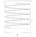
この状況を例示するために、図5は8個の等距離点で標本抽出された複素正弦信号(I成分及びQ成分は実数部及び虚数部のことを指している)を示している。この正弦波の周波数はf=1/(T・N・2)に選択されており、ここでTは標本抽出期間でありNはFFT演算の次数である。従って、fが最大低下点であり実際、8点FFTの振幅スペクトル(図6)において明らかな様に、信号は第二周波数ビンと第三周波数ビンとの間に分布している。 To illustrate this situation, FIG. 5 shows a complex sine signal sampled at eight equidistant points (I and Q components refer to the real and imaginary parts). The frequency of this sine wave is selected as f = 1 / (T · N · 2), where T is the sampling period and N is the order of the FFT operation. Therefore, f is the maximum drop point, and in fact, the signal is distributed between the second frequency bin and the third frequency bin, as is apparent in the amplitude spectrum of the 8-point FFT (FIG. 6).
図8は16点にゼロ埋込みされた図5の同じ入力信号についての16点FFTの振幅スペクトルを表しており、この場合にはピークが図5中よりも非常によく明示されているが、より大きな計算負荷を犠牲にしている。 FIG. 8 shows the amplitude spectrum of a 16-point FFT for the same input signal of FIG. 5 zero-padded to 16 points, in which case the peak is clearly shown much better than in FIG. At the expense of a large computational load.
別の公知の方法によると、検出閾値と比較される求められている半整数周波数成分を表している平均振幅を得るために、周波数振幅Mfの二つ以上の隣接ビンを結合させることができる。しかし、雑音変動と従って真の信号対雑音比(SNR)との増加によって、増加した感度がある程度は相殺されるので、これは最適な解決策ではない。According to another known method, two or more adjacent bins of the frequency amplitude Mf can be combined to obtain an average amplitude representing the desired half integer frequency component compared to the detection threshold. . However, this is not an optimal solution because the increase in noise variation and thus the true signal-to-noise ratio (SNR) offsets the increased sensitivity to some extent.
正規分布不規則信号によって表される雑音の場合には、統計的に独立しているN個の結果をFFT演算が発生させる、ということを考慮することが重要である。このことは、独立の実数部及び虚数部並びにゼロ平均及びσ標準偏差を各々が有している二つのFFTビンを加算することが、ゼロ平均及びσ(2)1/2標準偏差を有する新しい信号を生じさせる、ということを意味している。In the case of noise represented by a normally distributed irregular signal, it is important to consider that the FFT operation generates N results that are statistically independent. This means that adding two FFT bins, each with independent real and imaginary parts and zero mean and σ standard deviation, is new with zero mean and σ (2)1/2 standard deviation It means to generate a signal.
本発明によると、第一スペクトルの隣接ビンの各対毎に、この第一スペクトルの隣接ビンの位相及び振幅の結合によって与えられる中間周波数値を計算することによって、整数チップ周波数偏移及び半チップ周波数偏移を含む第二周波数スペクトルが得られる。 According to the present invention, for each pair of adjacent bins of the first spectrum, an integer chip frequency shift and a half chip are calculated by calculating an intermediate frequency value given by the phase and amplitude combination of the adjacent bins of this first spectrum. A second frequency spectrum including a frequency shift is obtained.
本発明の一つの形態によると、例えば
S′2k=Sk S′2k+1={Sk・exp(−jπ/2)+Sk+1・exp(jπ/2)}/(2)1/2 k=0,...N−2 (3)
によって補間スペクトルS′が与えられる。According to one embodiment of the present invention, for example, S ′2k = Sk S ′2k + 1 = {Sk · exp (−jπ / 2) + Sk + 1 · exp (jπ / 2)} / (2)1 / 2 k = 0,. . . N-2 (3)
Gives the interpolated spectrum S '.
ここでの関心事である、図5中に示されている様に初期入力関数が純粋に正弦波である場合における2N個のFFTの結果を、2N−1個のS′値が近似している。しかし、S′補間値の発生は、単一モジュールを有する一定係数による乗算と等価である複素和及び回転しか必要とせず、完全な2N個のFFT演算よりも計算がかなり少ない。 In this case, as shown in FIG. 5, when the initial input function is purely sinusoidal, 2N FFT results are approximated by 2N-1 S 'values. Yes. However, the generation of S 'interpolated values requires only complex sums and rotations, which are equivalent to multiplication by a constant coefficient with a single module, and are much less computationally than a full 2N FFT operation.
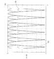
図7と関連して、約180°だけ位相外れであり従って上記の方法で使用される回転後に構成的に結合する位相値を、FFTの隣接点が有している、ということに留意することが重要である。このことは正弦波信号の初期位相とは無関係にその正弦波信号に当てはまる。 In connection with FIG. 7, note that the FFT neighbors have phase values that are out of phase by about 180 ° and thus constitutively combine after rotation as used in the above method. is important. This is true for the sinusoidal signal regardless of the initial phase of the sinusoidal signal.
図9は、本発明の補間方法によって得られ図5の正弦波信号から出発しているスペクトルを示している。 FIG. 9 shows the spectrum obtained by the interpolation method of the invention and starting from the sinusoidal signal of FIG.
本発明のこの変形についての感度低下が図10中に表されており、8点FFT(曲線102)、ゼロ埋込み後の16点FFT(曲線103)及び本発明の補間スペクトル(曲線104)の感度が図10に重ねられている。補間スペクトル104は、−1.025dBから最悪の場合の1.325dBへ変化する値に感度低下を限定している。 The sensitivity drop for this variation of the present invention is illustrated in FIG. 10, where the sensitivity of the 8-point FFT (curve 102), the 16-point FFT after zero padding (curve 103), and the interpolated spectrum of the present invention (curve 104) Are superimposed on FIG. The interpolated
アルガン−ガウス平面上では、図2に表されている様に、補間演算は、Skについては角度θ=π/2の反時計回り回転(または、数学的に等価な、j=exp(jπ/2)による複素積)、Sk+1については−θの時計回り回転(または、−jによる複素積)、及びそれらに続く複素和と係数2による正規化とに対応している。回転及び正規化のためのその様な値は、純粋に正弦波である入力の場合に、計算が最も便利な様に選択されており、理想的な結果に最良の近似を与える。しかし、これらは二つの隣接ビンを結合させる唯一の可能な方法ではなく、例えば異なる回転角度つまり異なる複素係数による乗算を伴う隣接値のその他の複素結合も本発明が含んでいる。Argan - on the Gaussian plane, as depicted in FIG. 2, the interpolation calculation is counter-clockwise rotation of the angle theta = [pi / 2 for Sk (or, mathematically equivalent, j = exp (jπ The complex product of / 2) and Sk + 1 correspond to the clockwise rotation of −θ (or the complex product of −j), and the subsequent complex sum and normalization by coefficient 2. Such values for rotation and normalization are chosen for the most convenient calculation in the case of inputs that are purely sinusoidal, giving the best approximation to ideal results. However, these are not the only possible ways of combining two adjacent bins, and other complex combinations of adjacent values involving, for example, different rotation angles or multiplications with different complex coefficients are included in the present invention.
一方、FFTスペクトルの二つ超の隣接ビンに関係する補間段階も本発明が含んでいてよい。例えば四つの隣接データが結合されてよい。 On the other hand, the present invention may also include interpolation steps relating to more than two adjacent bins of the FFT spectrum. For example, four adjacent data may be combined.
図3の流れ図は、本発明に従って、中間周波数値を含んでいる第二スペクトルを得る段階と処理する段階とを表している。N個のμt値は、図1の積算器64、62によって与えられ複素数として準備された積算相関値65、63である。各μtは、同相積算器64から得られた実数部Itと直角位相積算器62から得られた虚数部Qtとを有している。The flowchart of FIG. 3 represents the steps of obtaining and processing a second spectrum that includes intermediate frequency values in accordance with the present invention. The N μt values are integrated correlation values 65 and 63 prepared as complex numbers given by the
その後、μtはN点フーリエ変換、通常は、第一複素周波数スペクトルSfを与える高速フーリエ変換(FFT)91に供される。時系列μtを周波数スペクトルへ変換するその他の数学的変換が、等価的に可能であり、本発明の範囲内に含まれている。Μt is then subjected to an N-point Fourier transform, usually a fast Fourier transform (FFT) 91 that gives a first complex frequency spectrum Sf . Other mathematical transformations that transform the time series μt into the frequency spectrum are equivalently possible and are included within the scope of the present invention.
補間段階92は、2N−1個の補間S′値を含んでいる第二スペクトルS′を与える。S′の偶数インデックス値は、周波数偏移の整数値(周波数チップで表現されている)に対応しており、第一スペクトルの対応値Sに等しい。S′の奇数インデックス値は、周波数偏移の半整数値に対応しており、上述の様にSの二つの隣接値によって得られる。
第二スペクトルS′は、ピーク検出段階93によって更に処理されて、相関値95を与える。信号処理装置中の専用ハードウェアモジュールかまたは適切なソフトウェアルーチンによって実行することのできるピーク検出段階93は、S′の振幅と固定閾値との比較またはその他の何らかの公知のピーク検出方法を含んでいてよい。 The second spectrum S ′ is further processed by the
上記の例の様に全第一スペクトルSが補間されることは必ずしも必要ではない。本発明の変形では、全FFTスペクトルではなく、情況次第で、全FFTスペクトルの一部かまたは隣接ビン群のうちの特定の対のみが補間される。 It is not always necessary to interpolate the entire first spectrum S as in the above example. In a variation of the invention, not a full FFT spectrum, but only a specific pair of a part of the full FFT spectrum or a group of adjacent bins is interpolated depending on the situation.
Claims (9)
Translated fromJapanese局所化情報を含んでいる信号を得る段階と、
前記信号を局部擬似ランダム符号系列と結合させて相関信号を得る段階と、
前記相関信号の周波数の第一スペクトルを得る段階とを具備しており、
前記第一スペクトルの隣接ビンの振幅値及び位相値の複素結合によって、中間周波数データを含んでいる第二スペクトルを得る段階と、
前記第二スペクトル中のピークを探索する段階とを特徴とする方法。A method for capturing a positioning signal of a geographic localization system comprising:
Obtaining a signal containing localization information;
Combining the signal with a local pseudorandom code sequence to obtain a correlation signal;
Obtaining a first spectrum of the frequency of the correlation signal,
Obtaining a second spectrum containing intermediate frequency data by complex combination of amplitude and phase values of adjacent bins of the first spectrum;
Searching for a peak in said second spectrum.
前記対のうちの最初の値の、角度(θ)による第一複素回転と、
前記対のうちの別の値の、前記第一複素回転とは反対方向への、前記角度(θ)による第二複素回転と、
前記第一複素回転及び前記第二複素回転から生じる複素数の加算とを含んでいる、請求項2に記載の方法。Said step of calculating intermediate frequency data comprises:
A first complex rotation of the first value of the pair by an angle (θ);
A second complex rotation by said angle (θ) in a direction opposite to said first complex rotation of another value of said pair;
The method of claim 2 including adding complex numbers resulting from the first complex rotation and the second complex rotation.
S′2k+1={Sk・exp(−jπ/2)+Sk+1・exp(jπ/2)}/(2)1/2
の評価を含んでおり、ここで、S′2k+1は中間周波数値を表しており、Sk及びSk+1は前記第一スペクトルの隣接値の対のうちの第一及び第二の値を表している、請求項2に記載の方法。Said step of calculating intermediate frequency data comprises:
S ′2k + 1 = {Sk · exp (−jπ / 2) + Sk + 1 · exp (jπ / 2)} / (2)1/2
Where S ′2k + 1 represents the intermediate frequency value, and Sk and Sk + 1 are the first and second of the adjacent pairs of the first spectrum. The method of claim 2, wherein the method represents a value.
Applications Claiming Priority (1)
| Application Number | Priority Date | Filing Date | Title |
|---|---|---|---|
| EP05100791AEP1688755A1 (en) | 2005-02-04 | 2005-02-04 | FFT inter frequency loss mitigation and GPS receiver including it |
Publications (1)
| Publication Number | Publication Date |
|---|---|
| JP2006217601Atrue JP2006217601A (en) | 2006-08-17 |
Family
ID=34938644
Family Applications (1)
| Application Number | Title | Priority Date | Filing Date |
|---|---|---|---|
| JP2006020243APendingJP2006217601A (en) | 2005-02-04 | 2006-01-30 | Method for acquiring positioning signal of geographic localization system, receiver for geographic localization system and computer data carrier comprising program instruction for carrying out the method |
Country Status (3)
| Country | Link |
|---|---|
| US (1) | US7643542B2 (en) |
| EP (1) | EP1688755A1 (en) |
| JP (1) | JP2006217601A (en) |
Cited By (2)
| Publication number | Priority date | Publication date | Assignee | Title |
|---|---|---|---|---|
| JP2006234811A (en)* | 2005-02-25 | 2006-09-07 | Nemerix Sa | Method obtaining frequency difference between input signal and standard frequency and discriminator executing this method, gps receiver and computer program |
| JP2011508186A (en)* | 2007-11-28 | 2011-03-10 | トップコン ジーピーエス,エルエルシー | Method and apparatus for adaptive processing of signals received from a satellite navigation system |
Families Citing this family (2)
| Publication number | Priority date | Publication date | Assignee | Title |
|---|---|---|---|---|
| CN102176034B (en)* | 2011-03-09 | 2012-09-05 | 东南大学 | Satellite losing lock judging method of GPS (Global Positioning System) receiver |
| CN105204040A (en)* | 2015-09-18 | 2015-12-30 | 广州北航新兴产业技术研究院 | Satellite signal capturing system |
Family Cites Families (12)
| Publication number | Priority date | Publication date | Assignee | Title |
|---|---|---|---|---|
| EP0501828B1 (en)* | 1991-02-28 | 2000-01-12 | Texas Instruments Incorporated | Method and system for a multi channel and search global position signal processor |
| US6133873A (en)* | 1998-06-03 | 2000-10-17 | Krasner; Norman F. | Method and apparatus for adaptively processing GPS signals in a GPS receiver |
| US6795424B1 (en)* | 1998-06-30 | 2004-09-21 | Tellabs Operations, Inc. | Method and apparatus for interference suppression in orthogonal frequency division multiplexed (OFDM) wireless communication systems |
| US6683923B1 (en)* | 1999-04-16 | 2004-01-27 | Bd Systems, Inc. | Method and apparatus for detecting and tracking coded signals in a noisy background environment |
| US6642884B2 (en)* | 2000-05-08 | 2003-11-04 | Sigtec Navigation Pty Ltd. | Satellite-based positioning system receiver for weak signal operation |
| WO2002013476A1 (en)* | 2000-08-09 | 2002-02-14 | Skybitz, Inc. | System and method for fast code phase and carrier frequency acquisition in gps receiver |
| AU2002228996A1 (en)* | 2000-12-20 | 2002-07-01 | The Johns Hopkins University | Gps receiver tracking system |
| US6633253B2 (en)* | 2001-04-02 | 2003-10-14 | Thomas J. Cataldo | Dual synthetic aperture radar system |
| US7436881B2 (en)* | 2001-09-28 | 2008-10-14 | Nec Corporation | Per-bin DFE for advanced OQAM-based multi-carrier wireless data transmission systems |
| US7065629B2 (en)* | 2002-11-18 | 2006-06-20 | Rf Micro Devices, Inc. | Address translation logic for use in a GPS receiver |
| WO2005022187A2 (en)* | 2003-09-02 | 2005-03-10 | Sirf Technology, Inc. | Control and features for satellite positioning system receivers |
| US7472152B1 (en)* | 2004-08-02 | 2008-12-30 | The United States Of America As Represented By The Secretary Of The Air Force | Accommodating fourier transformation attenuation between transform term frequencies |
- 2005
- 2005-02-04EPEP05100791Apatent/EP1688755A1/ennot_activeCeased
- 2006
- 2006-01-30JPJP2006020243Apatent/JP2006217601A/enactivePending
- 2006-01-31USUS11/343,444patent/US7643542B2/ennot_activeExpired - Fee Related
Cited By (3)
| Publication number | Priority date | Publication date | Assignee | Title |
|---|---|---|---|---|
| JP2006234811A (en)* | 2005-02-25 | 2006-09-07 | Nemerix Sa | Method obtaining frequency difference between input signal and standard frequency and discriminator executing this method, gps receiver and computer program |
| JP2012168187A (en)* | 2005-02-25 | 2012-09-06 | Qualcomm Inc | Method of obtaining frequency difference between input signal and reference frequency, and discriminator, gps receiver and computer program to implement this method |
| JP2011508186A (en)* | 2007-11-28 | 2011-03-10 | トップコン ジーピーエス,エルエルシー | Method and apparatus for adaptive processing of signals received from a satellite navigation system |
Also Published As
| Publication number | Publication date |
|---|---|
| EP1688755A1 (en) | 2006-08-09 |
| US7643542B2 (en) | 2010-01-05 |
| US20060251157A1 (en) | 2006-11-09 |
Similar Documents
| Publication | Publication Date | Title |
|---|---|---|
| EP0083480B1 (en) | Receivers for navigation satellite systems | |
| US6466958B1 (en) | Parallel frequency searching in an acquisition correlator | |
| JP4498841B2 (en) | GPS correlation peak signal search method and system therefor. | |
| US20150204981A1 (en) | Signal processing method for ultra-fast acquisition and tracking of severely attenuated spread spectrum signals with doppler frequency and apparatus thereof | |
| CN116482727B (en) | Navigation signal tracking method, device, equipment and chip | |
| EP2006706B1 (en) | Coherent integration enhancement method, positioning method, storage medium, coherent integration enhancement circuit, positioning circuit, and electronic instrument | |
| US7696925B2 (en) | Memory reduction in GNSS receiver | |
| CN114114335A (en) | A fast acquisition method for weak signal GNSS receiver | |
| Tamazin et al. | Robust fine acquisition algorithm for GPS receiver with limited resources | |
| Leclere et al. | Modified parallel code-phase search for acquisition in presence of sign transition | |
| JP2009510471A (en) | Data demodulation from weak navigation satellite signals | |
| Ahamed et al. | Fast acquisition of GPS signal using Radix-2 and Radix-4 FFT algorithms | |
| JP2006217601A (en) | Method for acquiring positioning signal of geographic localization system, receiver for geographic localization system and computer data carrier comprising program instruction for carrying out the method | |
| JP5321500B2 (en) | Signal acquisition method | |
| US20120274512A1 (en) | Signal Processing Method, Device and System | |
| Li et al. | Preliminary insights on fast GNSS signal capture using SFT and FFT frequency shift | |
| CN112764063A (en) | Method for realizing capture processing and receiver | |
| JP6253855B1 (en) | Signal acquisition device | |
| Lin et al. | Acquisition of GPS software receiver using split-radix FFT | |
| Wang et al. | Fast GNSS satellite signal acquisition method based on multiple resamplings | |
| CN107132552B (en) | Parallel code phase searching device and method for realizing parallel code phase searching | |
| CN107132555B (en) | A kind of parallel code phase search device and the method for realizing parallel code phase search | |
| Mao et al. | New acquisition method in GPS software receiver with split-radix FFT technique | |
| US20230288574A1 (en) | Modernized global navigation satellite system (gnss) receivers and commercially viable consumer grade gnss receivers | |
| JP4559780B2 (en) | GPS correlation peak signal search method and system therefor |