JP2006216042A - System and method for interruption processing - Google Patents
System and method for interruption processingDownload PDFInfo
- Publication number
- JP2006216042A JP2006216042AJP2006021904AJP2006021904AJP2006216042AJP 2006216042 AJP2006216042 AJP 2006216042AJP 2006021904 AJP2006021904 AJP 2006021904AJP 2006021904 AJP2006021904 AJP 2006021904AJP 2006216042 AJP2006216042 AJP 2006216042A
- Authority
- JP
- Japan
- Prior art keywords
- processor
- task
- priority
- designated
- interrupt
- Prior art date
- Legal status (The legal status is an assumption and is not a legal conclusion. Google has not performed a legal analysis and makes no representation as to the accuracy of the status listed.)
- Pending
Links
Images


Classifications
- G—PHYSICS
- G06—COMPUTING OR CALCULATING; COUNTING
- G06F—ELECTRIC DIGITAL DATA PROCESSING
- G06F9/00—Arrangements for program control, e.g. control units
- G06F9/06—Arrangements for program control, e.g. control units using stored programs, i.e. using an internal store of processing equipment to receive or retain programs
- G06F9/46—Multiprogramming arrangements
- G06F9/48—Program initiating; Program switching, e.g. by interrupt
- G06F9/4806—Task transfer initiation or dispatching
- G06F9/4812—Task transfer initiation or dispatching by interrupt, e.g. masked
- G—PHYSICS
- G06—COMPUTING OR CALCULATING; COUNTING
- G06F—ELECTRIC DIGITAL DATA PROCESSING
- G06F13/00—Interconnection of, or transfer of information or other signals between, memories, input/output devices or central processing units
- G06F13/14—Handling requests for interconnection or transfer
- G06F13/20—Handling requests for interconnection or transfer for access to input/output bus
- G06F13/24—Handling requests for interconnection or transfer for access to input/output bus using interrupt
- G06F13/26—Handling requests for interconnection or transfer for access to input/output bus using interrupt with priority control
Landscapes
- Engineering & Computer Science (AREA)
- Theoretical Computer Science (AREA)
- Physics & Mathematics (AREA)
- General Engineering & Computer Science (AREA)
- General Physics & Mathematics (AREA)
- Software Systems (AREA)
- Multi Processors (AREA)
- Bus Control (AREA)
Abstract
Description
Translated fromJapanese本発明は、マルチプロセッサシステムにおいて割り込みを処理する技術に関する。 The present invention relates to a technique for handling an interrupt in a multiprocessor system.
マルチプロセッサシステムは、特定のアーキテクチャによって様々であるが、典型的には、デバイスやプロセッサ・タスクから発生する信号と割り込みを処理するためにサブシステムを用いている。典型的なマルチプロセッサシステムは、中央プロセッサ、複数のサブプロセッサ、メモリ、システムバス、およびデバイスやデータネットワークと通信するための入出力チャネルを含む。 Multiprocessor systems vary depending on the particular architecture, but typically use subsystems to handle signals and interrupts originating from devices and processor tasks. A typical multiprocessor system includes a central processor, multiple sub-processors, memory, a system bus, and input / output channels for communicating with devices and data networks.
あるマルチプロセッサシステムは、中央プロセッサを通して割り込みの処理を試みる。中央プロセッサは、割り込みが発生したときにその割り込みを処理するための一つ以上のサブプロセッサを指定し、システム機器からの割り込みを受け取ると、指定されたサブプロセッサに割込みタスクがシステムバスを介して送られる。しかし、特に高度に複雑なシステムでは、割り込み処理を集中して行うと、中央プロセッサにおいて「ボトルネック」となりうる。 Some multiprocessor systems attempt to handle interrupts through a central processor. When an interrupt occurs, the central processor designates one or more subprocessors to handle the interrupt, and when an interrupt is received from the system device, an interrupt task is sent to the designated subprocessor via the system bus. Sent. However, particularly in highly complex systems, centralized interrupt processing can be a “bottleneck” in the central processor.
他のシステムでは、マルチプロセッサシステムは、全てのサブプロセッサに割り込みをブロードキャストするためにパラレルバスを用いている。1つ以上のサブプロセッサが割り込みを受け取り、その後割り込みタスクを実行するために指定されている。しかし、そのようなシステムは、マルチプロセッサシステムのサイズが大きくなり、それに伴って、全てのプロセッサにブロードキャストされる割り込みの数が増加するにつれて、輻輳問題に悩まされることになる。 In other systems, multiprocessor systems use a parallel bus to broadcast interrupts to all subprocessors. One or more sub-processors are designated to receive the interrupt and then execute the interrupt task. However, such systems suffer from congestion problems as the size of multiprocessor systems increases and the number of interrupts broadcast to all processors increases accordingly.
本発明はこうした課題に鑑みてなされたものであり、その目的は、マルチプロセッサシステムにおいて割り込み処理を効率良く行う技術を提供することにある。 The present invention has been made in view of these problems, and an object thereof is to provide a technique for efficiently performing interrupt processing in a multiprocessor system.
上記課題を解決するために、本発明のある態様は、マルチプロセッサシステムにおいて割り込みを処理する方法である。この方法は、プロセッサ毎に指定値を格納しておき、前記指定値を参照して、各プロセッサが、自分が前記システムに対する割り込みを処理するために指定されたプロセッサであるかどうかを特定するステップと、前記指定されたプロセッサが、他の複数のプロセッサの内のどのプロセッサが次に指定されるべきかを選択するステップとを含む。前記指定されたプロセッサが自分自身とは異なるプロセッサを選択する場合、前記指定されたプロセッサは、前記選択されたプロセッサが前記指定されたプロセッサであることを示すように、自分自身の前記指定値と前記選択されたプロセッサの前記指定値とを変更する。 In order to solve the above problems, an aspect of the present invention is a method of handling an interrupt in a multiprocessor system. In this method, a specified value is stored for each processor, and referring to the specified value, each processor determines whether it is a specified processor for handling an interrupt to the system. And the designated processor includes selecting which one of the other processors to be designated next. If the designated processor selects a different processor than itself, the designated processor is configured with its designated value to indicate that the selected processor is the designated processor. The specified value of the selected processor is changed.
本発明の別の態様は、複数のプロセッサを含むシステムにおいて割り込みを処理する方法である。この方法は、メモリが前記複数のプロセッサの内、どの1つのプロセッサが指定されたプロセッサであるかを示しており、前記指定されたプロセッサにおいて割り込みを処理するステップと、前記指定されたプロセッサが、自分自身か前記複数のプロセッサのうちの別の1つのプロセッサを指定されたプロセッサとして選択するステップとを含む。前記指定されたプロセッサが、前記複数のプロセッサのうちの別の1つのプロセッサが指定されたプロセッサになるべきであると判定するならば、前記指定されたプロセッサは、前記別の1つのプロセッサが指定されたプロセッサであることを示すように前記メモリを変更する。 Another aspect of the present invention is a method for handling interrupts in a system including a plurality of processors. The method indicates which one of the plurality of processors is the designated processor, the step of handling an interrupt in the designated processor, and the designated processor comprises: Selecting itself or another one of the plurality of processors as a designated processor. If the designated processor determines that another one of the plurality of processors should be the designated processor, the designated processor is designated by the other one processor. The memory is changed to indicate that the processor has been changed.
本発明のさらに別の態様は、マルチプロセッサシステムである。このマルチプロセッサシステムは、プロセッサの識別情報と優先度の識別情報とを格納する優先度テーブルと、第1優先度レベルにおいて非割り込みタスクを処理する第1プロセッサと、第2優先度レベルにおいて割り込みタスクを処理する第2プロセッサとを含む。前記第1プロセッサは、前記第1優先度レベルが前記優先度テーブルに格納された優先度以下であるならば、前記第1優先度レベルとプロセッサの識別情報を前記優先度テーブルに書き込み、前記第2プロセッサは、タスク切替時に、前記優先度テーブルにおいて、より低い優先度レベルをもつ別のプロセッサがあるかどうかを調べ、もし見つかった場合、前記第1プロセッサを指定してその後の割り込みの処理をさせる。 Yet another aspect of the present invention is a multiprocessor system. The multiprocessor system includes a priority table for storing processor identification information and priority identification information, a first processor for processing a non-interrupt task at a first priority level, and an interrupt task at a second priority level. And a second processor for processing. If the first priority level is equal to or lower than the priority stored in the priority table, the first processor writes the first priority level and processor identification information to the priority table; At the time of task switching, the two processors check whether there is another processor having a lower priority level in the priority table, and if found, specify the first processor and perform subsequent interrupt processing. Let
本発明のさらに別の態様は、マルチプロセッサシステムにおいて割り込みを処理する方法である。この方法は、システムバスを介して通信する複数のプロセッサを設け、前記複数のプロセッサは複数の優先度レベルで複数のタスクを実行する機能を有し、前記複数のプロセッサの各々にはタスクメモリが関連づけられている。複数のプロセッサ用の記憶領域をシステムメモリに設け、前記システムメモリは、前記システムバスを介して複数のプロセッサと情報のやりとりが可能であり、前記システムメモリは、前記複数のプロセッサと関連づけられた複数の優先度レベルの内、最下位優先度レベルを記憶するための記憶構造を有する。前記記憶構造を介して、前記複数のプロセッサの内、最下位優先度レベルをもつ第1プロセッサを最下位優先度プロセッサとして指定し、前記第1プロセッサが最下位優先度プロセッサとして指定されるように前記最下位優先度プロセッサの前記タスクメモリを設定する。割り込み生成器の指定レジスタが前記最下位優先度プロセッサと関連づけられるように設定し、前記割り込み生成器によって生成される第3タスクを直接、前記最下位優先度プロセッサに送り、タスクが切り替えられるまでは、前記最下位優先度プロセッサにおいて前記第3タスクを処理する。タスク切り替えが起きた際、前記最下位優先度プロセッサにおいて、前記最下位優先度プロセッサが前記複数のプロセッサの中で最下位優先度レベルを依然としてもつかどうかを判定し、もしそうでないならば、前記複数のプロセッサの内、最下位優先度をもつ第2プロセッサが最下位優先度プロセッサとして指定されるように前記第2プロセッサのタスクメモリを設定することにより、前記第2プロセッサを前記最下位優先度プロセッサとして指定し、前記割り込み生成器の前記指定レジスタを前記第2プロセッサを指すように更新し、前記第1プロセッサの前記タスクメモリの設定を解除する。 Yet another aspect of the present invention is a method of handling an interrupt in a multiprocessor system. This method includes a plurality of processors communicating via a system bus, the plurality of processors having a function of executing a plurality of tasks at a plurality of priority levels, and each of the plurality of processors has a task memory. Is associated. A storage area for a plurality of processors is provided in a system memory, the system memory can exchange information with a plurality of processors via the system bus, and the system memory is associated with the plurality of processors. A storage structure for storing the lowest priority level among the priority levels. Via the storage structure, a first processor having the lowest priority level among the plurality of processors is designated as the lowest priority processor, and the first processor is designated as the lowest priority processor. Set the task memory of the lowest priority processor. Set the interrupt generator's designated register to be associated with the lowest priority processor and send the third task generated by the interrupt generator directly to the lowest priority processor until the task is switched The third task is processed in the lowest priority processor. When a task switch occurs, the lowest priority processor determines whether the lowest priority processor still has the lowest priority level among the plurality of processors, and if not, the By setting the task memory of the second processor such that the second processor having the lowest priority among the plurality of processors is designated as the lowest priority processor, the second processor is set to the lowest priority. Designate as a processor, update the designation register of the interrupt generator to point to the second processor, and cancel the setting of the task memory of the first processor.
本発明のさらに別の態様は、分散割り込み処理システムである。このシステムは、システムバスを介して接続された複数のプロセッサを含み、各プロセッサは、第1タスクと第2タスクを実行するためのオペレーティングシステムカーネルを含み、各プロセッサは優先度レベルをもち、各プロセッサが前記複数のプロセッサの中で最下位優先度プロセッサであるかどうかを識別するためのタスクメモリが各プロセッサに関連づけられている。前記システムバスを介して前記複数のプロセッサからアクセス可能なシステムメモリであって、少なくとも前記最下位優先度プロセッサおよび前記複数のプロセッサの最下位優先度レベルに関連づけられた記憶構造を有するシステムメモリと、前記最下位優先度プロセッサと関連づけられた指定レジスタを含む割り込み生成器とを含む。前記割り込み生成器により生成された第3タスクが、実行のために前記システムバスを介して前記最下位優先度プロセッサに直接送られる。前記第1タスクから前記第2タスクに切り替えるタスク切り替えの際に前記優先度の構造が更新される。前記最下位優先度プロセッサが前記優先度の構造においてもはや最下位優先度ではないならば、前記最下位優先度プロセッサは、前記複数のプロセッサの中で第2プロセッサの前記関連づけられたタスクメモリを設定し、前記割り込み生成器の前記指定レジスタを更新し、前記最下位優先度プロセッサの前記関連づけられたタスクメモリの設定を解除することにより、前記第2プロセッサを第2の最下位優先度プロセッサとして指定する。 Yet another embodiment of the present invention is a distributed interrupt processing system. The system includes a plurality of processors connected via a system bus, each processor including an operating system kernel for executing a first task and a second task, each processor having a priority level, Associated with each processor is a task memory for identifying whether the processor is the lowest priority processor among the plurality of processors. System memory accessible from the plurality of processors via the system bus, the system memory having a storage structure associated with at least the lowest priority processor and a lowest priority level of the plurality of processors; And an interrupt generator including a designated register associated with the lowest priority processor. A third task generated by the interrupt generator is sent directly to the lowest priority processor via the system bus for execution. The priority structure is updated when the task is switched from the first task to the second task. If the lowest priority processor is no longer the lowest priority in the priority structure, the lowest priority processor sets the associated task memory of a second processor among the plurality of processors. The second processor is designated as the second lowest priority processor by updating the designation register of the interrupt generator and releasing the setting of the associated task memory of the lowest priority processor. To do.
なお、以上の構成要素の任意の組合せ、本発明の表現を方法、装置、システム、コンピュータプログラム、データ構造、記録媒体などの間で変換したものもまた、本発明の態様として有効である。 It should be noted that any combination of the above-described constituent elements and the expression of the present invention converted between a method, an apparatus, a system, a computer program, a data structure, a recording medium, etc. are also effective as an aspect of the present invention.
本発明によれば、マルチプロセッサシステムにおいて割り込み処理を効率良く行うことができる。 According to the present invention, interrupt processing can be efficiently performed in a multiprocessor system.
図1は、本発明のいろいろな態様において採用することのできる基本的な処理モジュールであるプロセッサ要素(PE)100の構成図である。同図に示されるように、PE100は、I/Oインタフェース102と、処理ユニット(PU)104と、ダイレクトメモリアクセスコントローラ(DMAC)106と、複数のサブ処理ユニット(SPU)108、すなわち、SPU群108A〜108Dとを含む。ここでは4つのSPUが図示されているが、PE100は任意の数のSPUのようなデバイスを含んでもよい。ローカル(すなわち内部)PEバス120は、PU104、SPU群108、I/Oインタフェース102、DMAC106およびメモリインタフェース110間のデータおよびアプリケーションの伝送を行う。ローカルPEバス120は、例えば従来構成でもよいし、またはパケットスイッチネットワークとして実装することもできる。パケットスイッチネットワークとして実装するとより多くのハードウェアが必要になるが、利用可能な帯域が広がる。 FIG. 1 is a block diagram of a processor element (PE) 100, which is a basic processing module that can be employed in various aspects of the present invention. As shown in the figure, the
PE100は、タイマ180をさらに含むか、タイマ180にアクセスする。ここではタイマ180は、PEの内部にあるように示されているが、PEの外部に設けられてもよい。 The PE 100 further includes or accesses the
PE100は、内部的に、かつ、PE100の外部のエレメントから支援されることなく、どのSPUがタスクの優先度レベルに基づいて特定のタスクを実行するかを判定することができることが好ましい。たとえば、PU104は、タスクの優先度レベルに基づいて、どのSPU108が現在タスクを引き受けることが可能であるかを判定する。PU104はまた、SPUが優先順位の高いタスクを引き受けるために、それ自身の現在のタスクを別のプロセッサ(内部もしくは外部のPE100)に切り替えるべきかどうかを判定する。 The
PE100は、割り込み発生器(IG)150を更に含んでもよい。割り込み発生器(IG)150は、保留(ペンディング)中の割り込み要求があるかどうかを示す情報を提供する。 The
IG150によって管理される割り込み情報は、IG150自体やPE100内の他のエレメントを含む任意のソースから来る割り込み、もしくはPEに接続されたデバイス、たとえばデバイス170(それは図2で示すようなI/O制御部212を含んでもよい)から来る割り込みに由来するものであってもよい。IG150は、専用の割込み信号線上で直接デバイス170から割込み要求を受け取ってもよく、あるいは、I/Oインタフェース102とローカルPEバス120を介して情報を受け取ってもよい。 The interrupt information managed by the IG 150 includes interrupts coming from any source including the
IG150は、例えばローカルPEバス120を介して、PE100の他のエレメントに情報を送ってもよい。PE100の他のエレメント、例えばPU104またはいずれかのSPU108が、情報を得るためにIG150にポーリングしてもよい。 The IG 150 may send information to other elements of the PE 100 via the
好ましくは、IG150は、指定レジスタ(Specify Register)151、ポーリングレジスタ152のいずれかを含むか、あるいは両方を含む。図1の中の点線は、発明のある実施の形態は一方のレジスタを含み、他方のレジスタは含まないという事実を示すことを意図している。この点に関して、「指定レジスタの実施例」と称する場合は、以下に示すように指定レジスタ151を使うが、ポーリングレジスタ152を使わないPEまたは他のシステムを指す。同様に、「ポーリングレジスタの実施例」と称する場合は、以下に示すようにポーリングレジスタ152を使うが、指定レジスタ151を使わないPEまたは他のシステムを指す。 Preferably, the IG 150 includes one or both of a
指定レジスタの実施例、ポーリングレジスタの実施例のどちらにおいても、IG150もしくはその他の任意のエレメントは、PEの様々なプロセッサ、たとえばSPU108やPU104に対して割り込み情報をブロードキャストする必要がない。さらに、システムのこのような側面は、専用の割り込みチャネルや、アービトレーション、コンフリクト解消の必要性をなくすのに役立ち、それに伴ってオーバーヘッドを下げ、ボトルネックになることなく大きなシステムへのスケーラビリティの可能性を高める。しかしながら、本発明のいろいろな実施例により、そのようなブロードキャスト、チャンネル、アービトレーションまたはコンフリクト解消を不要とすることができる一方で、そのような方法やシステムは、本発明と相容れないものではなく、本発明とともに用いてもかまわない。 In either the designated register embodiment or the polling register embodiment, the
指定レジスタ151は、複数のSPU108のうちの1つを指す値を格納しており、それは、通常、どのSPUが割込み要求を処理しなければならないかを示すために用いられる。 The designation register 151 stores a value that points to one of the plurality of SPUs 108, which is typically used to indicate which SPU should process the interrupt request.
さらに、指定レジスタの実施例において、IG150は、好ましくは、指定レジスタ151によって指定されるSPU108にバス120を介して割り込みパケットを送るように構成されるのが好ましい。割り込みパケットは、SPUが割り込みに応じるために必要とする情報を含む。たとえば、割り込みパケットは、割込みハンドラタスクであってもよく、あるいはそのタスクへのポインタであってもよい。割り込みパケットはまた、割り込みと、その割り込みの発信元(ソース)の識別情報やユーザー定義の情報などのデータとを処理すべきプロセッサのアドレスを含んでもよい。 Further, in the designated register embodiment, the
ポーリングレジスタ152は、割込み要求がペンディングしているかどうかに関する情報、たとえば割り込みパケットへのポインタや割り込みが起きた理由などの情報を格納する。 The polling register 152 stores information regarding whether or not an interrupt request is pending, for example, information such as a pointer to an interrupt packet and a reason why an interrupt has occurred.
優先度テーブルは、どのプロセッサが次の割り込みを処理すべきかを決定するのを手助けするプロセッサからアクセス可能なメモリに格納される。優先度テーブルは、そのテーブルを用いるシステムエレメントからアクセス可能である限り、システム内部もしくはシステム外部の他のエレメントに設けられてもよい。たとえば、PE200は、タスク実行中の複数のSPU108の集合を含むため、優先度テーブル160は、DMAC106に格納されてもよい。実質的にDMAC106は、PE100から構成されるシステムのためのシステム全体のメモリとして動作するからである。優先度テーブル160に含まれる情報は、SPU108にとって、アトミック命令とアトミック・キャッシュを介してアクセス可能であってもよい。優先度テーブルをキャッシュメモリ、例えばPU104のL1キャッシュまたはL2キャッシュ、または、個々のSPUのアトミック・キャッシュに格納することもまた好ましい。 The priority table is stored in a memory accessible to the processor that helps determine which processor should handle the next interrupt. The priority table may be provided in other elements inside or outside the system as long as the priority table is accessible from the system element using the table. For example, since the
本発明のある態様では、優先度テーブルは、2つだけの情報を格納する。その2つの情報とは、複数のSPU108のうちの1つへのポインタと、そのSPUによって実行されているタスクの優先度レベルに等しいかそれを指し示す値である。たとえば、ポインタが複数のSPU108のうちの1つに割り当てられるユニークなIDから構成されるならば、優先度テーブル160の総サイズは8バイトであり、ユニークなIDは4バイト長、優先度レベルは4バイト長である。ここでの説明は、ある特定の側面においてはPU104に適用されてもよい。たとえば、PU104は、最下位プロセッサとして機能してもよく、その場合、ポインタはPU104を特定してもよい。 In one aspect of the invention, the priority table stores only two pieces of information. The two pieces of information are a pointer to one of the plurality of SPUs 108 and a value equal to or indicating the priority level of the task being executed by the SPU. For example, if the pointer is composed of a unique ID assigned to one of a plurality of SPUs 108, the total size of the priority table 160 is 8 bytes, the unique ID is 4 bytes long, and the priority level is It is 4 bytes long. The description herein may be applied to the
PE100はディジタルロジック回路を実装する各種方法を利用して構成できる。ただし好適には、PE100はシリコン基板上の相補的金属酸化膜半導体(CMOS)を用いる一つの集積回路として構成される。PE100は、広帯域メモリ接続122を介してメモリ130に密接に関連付けられる。メモリ130は、PE100に対するメインメモリとして機能することが望ましい。メモリ130は好適にはダイナミックランダムアクセスメモリ(DRAM)であるが、スタティックランダムアクセスメモリ(SRAM)、磁気ランダムアクセスメモリ(MRAM)、光学メモリ、またはホログラフィックメモリ等の他の手段を用いて実装してもよい。DMAC106とメモリインタフェース110は、メモリ130と、PE100のSPU108およびPU104との間のデータの転送を円滑にするものである。 The
PU104は、例えばスタンドアロン式のデータおよびアプリケーション処理が可能な標準的なプロセッサでもよい。動作時には、PU104はSPU群によるデータおよびアプリケーションの処理のスケジューリングおよび調整を行う。別の構成として、PE100は、複数のPU104を含んでもよい。複数のPU104の各々は、複数のSPU108の内、1つのSPU、すべてのSPU、ある指定されたSPUのグループを制御してもよい。SPUは、好適には、一命令複数データ(SIMD)プロセッサである。PU104の制御下で、複数のSPU108は、データおよびアプリケーションの処理を並列に、かつ独立して行ってもよい。好適には、PE100のようなPEがたくさん集まって結合されたり、1つにまとめられ、あるいは、論理的に互いに関連づけられて、処理能力が強化されてもよい。 The
図2は、本発明のいろいろな態様において動作しうる複数のPE200(PE1、PE2、PE3およびPE4)を含む処理アーキテクチャを示す。好ましくは、複数のPE200は単一のチップ上に設けられる。PE200は、図1のPE100に関して上述したようなPUやSPU群のようなサブシステムを含んでもよいし、含まなくてもよい。複数のPE200は、要求される処理の種類に応じて、同じタイプのものであってもよく、異なるタイプのものであってもよい。たとえば、複数のPE200の内、1つ以上のPEは、一般的なマイクロプロセッサ、デジタルシグナルプロセッサ(DSP)、グラフィックプロセッサ、マイクロコントローラなどであってもよい。 FIG. 2 illustrates a processing architecture that includes a plurality of PEs 200 (PE1, PE2, PE3, and PE4) that may operate in various aspects of the present invention. Preferably, the plurality of
複数のPE200は共有バス202につながっていることが好ましい。メモリ制御部であるDMAC206がメモリバス204を介して共有バス202に接続されていてもよい。DMAC206はメモリ208に接続されており、メモリ208は、上述したメモリ130のいくつかのタイプの1つであってもよい。I/O制御部212もまた、I/Oバス210を介して共有バス202に接続されてもよい。I/O制御部212は、フレームバッファ、ディスクドライブのような1つ以上のI/Oデバイス214と接続されてもよい。上述の処理モジュールおよびアーキテクチャは単なる例示であり、本発明のいろいろな態様が他の構成を利用して実現されても良い。他の構成として、たとえば、2003年2月25日に発行された米国特許第6,526,491号公報(発明の名称は"Memory Protection System and Method for Computer Architecture for Broadband Newtworks")や、2001年3月22日に出願された米国特許出願第09/816,004号(発明の名称は"Computer Architecture and Software Cells for Broadband Networks)に開示されたタイプのマルチプロセッサシステムがあるが、これに限られるわけではない。 The plurality of
基本処理モジュールであるプロセッサ要素はモジュラー構造をもち、プロセッサ要素内に任意の数のサブ処理ユニットを設けることができる。プロセッサ要素が搭載されるPC、サーバ、携帯機器、ゲーム機、家電製品などの各種情報機器に要求される処理性能に応じて、サブ処理ユニットの数を設計すればよい。また、情報機器には1つ以上のプロセッサ要素を設けてもよく、プロセッサ要素の数は、当該情報機器に要求される処理性能に応じて適宜選択することができる。さらにプロセッサ要素を搭載したノードがネットワークを介して接続されてなる分散処理システムを構成してもよく、当該分散処理システムに要求される処理性能に応じて、各ノードに搭載されるプロセッサ要素の数やプロセッサ要素内のサブ処理ユニットの数を設計してもよい。プロセッサ要素がモジュラー構造をもつことから、要求性能に応じてプロセッサ要素内のサブ処理ユニットの数やプロセッサ要素の数を任意に選択して実装することができ、システムに柔軟性や拡張性をもたせることができる。 The processor element which is a basic processing module has a modular structure, and any number of sub-processing units can be provided in the processor element. What is necessary is just to design the number of sub-processing units according to the processing performance requested | required of various information devices, such as PC, a server, a portable device, a game machine, and household appliances in which a processor element is mounted. Further, one or more processor elements may be provided in the information device, and the number of processor elements can be appropriately selected according to the processing performance required for the information device. Furthermore, a distributed processing system in which nodes equipped with processor elements are connected via a network may be configured, and the number of processor elements installed in each node according to the processing performance required for the distributed processing system. And the number of sub-processing units in the processor element may be designed. Since the processor element has a modular structure, the number of sub-processing units in the processor element and the number of processor elements can be selected and implemented according to the required performance, giving the system flexibility and expandability. be able to.
図3は、本発明のいろいろな態様で採用されうるSPU300の好適な構造と機能を示す図である。1つ以上のSPU300がPE100内に統合されてもよい。PEが複数のPU104を含む場合、複数のPU104の各々は、複数のSPU300の内、1つのSPU、すべてのSPU、ある指定されたSPUのグループを制御してもよい。 FIG. 3 is a diagram illustrating a preferred structure and function of an
SPU300は、ローカルストア(LS)302、レジスタ群304、一つ以上の浮動小数点ユニット306、および一つ以上の整数ユニット308を含むか、論理的に関連づけられていることが好ましい。SPU300のコンポーネントは、以下に説明するようなサブコンポーネントを含むことになる。要求される処理能力に応じて、より多くの、あるいはより少ない数の浮動小数点ユニット(FPU)306および整数ユニット(IU)308が用いられてもよい。ある好適な実施の形態において、ローカルストア302は、少なくとも128キロバイトの記憶領域を有し、レジスタ群304の容量は128×128ビットである。浮動小数点ユニット306は、好ましくは少なくとも毎秒32ギガ浮動小数点オペレーション(32GFLOPS)の速度で動作し、整数ユニット308は、好ましくは少なくとも毎秒32ギガオペレーション(32GOPS)の速度で動作する。
ローカルストア302は、キャッシュメモリではないことが好ましい。SPU300に対してキャッシュの一貫性をサポートする必要はない。その代わりに、ローカルストア302は、SRAMとして構成されるのが好ましい。PU104によって開始されたダイレクトメモリアクセスに対してはキャッシュの一貫性がサポートされることが必要になることがある。しかしながら、SPU300によって開始されたダイレクトメモリアクセスや、たとえばI/Oデバイス214のような外部デバイスに対するアクセスに対しては、キャッシュの一貫性のサポートは要求されない。ローカルストア302は、たとえば、特定のSPU300と関連づけられた物理メモリ、SPU300と関連づけられた仮想メモリ領域、物理メモリと仮想メモリの組み合わせ、あるいは、等価なハードウエア、ソフトウエアおよび/またはファームウエアの構成として実装してもよい。ローカルストア302がSPU300の外部にある場合、ローカルストア302は、SPU特有のローカルバスを介してSPU300と結合されてもよく、あるいは、ローカルPEバス120のようなシステムバスを介して結合されてもよい。 The
SPU300は、バスインタフェース312を介して、SPU300との間でアプリケーションとデータを伝送するためのバス310をさらに含む。ある好適な実施の形態において、バス310は1024ビット幅である。SPU300は、さらに内部バス314、316および318を含む。ある好適な実施の形態において、バス314は256ビット幅であり、ローカルストア302とレジスタ群304の間の通信を提供する。バス316とバス318は、それぞれ、レジスタ群304と浮動小数点ユニット306の間の通信、レジスタ群304と整数ユニット308の間の通信を提供する。ある好適な実施の形態において、レジスタ群304から浮動小数点ユニットまたは整数ユニットへのバス316および318のビット幅は384ビットであり、浮動小数点ユニットまたは整数ユニットへのバス316および318からレジスタ群304へのバス316および318のビット幅は128ビットである。レジスタ群304から浮動小数点ユニット306および整数ユニット308へのバス幅が大きくなればなるほど、処理中にレジスタ群304からのより大きなデータフローに対応することができる。ある例では、各演算には最大3ワードが必要とされるが、各演算の結果は通常1ワードである。 The
好ましくは、各々のSPUは識別子をもっており、優先度テーブル160は、その識別子を用いることでSPUを特定することができる。もっとも、SPUを指し示すための優先度テーブルには、任意のデータ構造またはその種のものが用いられてもよい。 Preferably, each SPU has an identifier, and the priority table 160 can identify the SPU by using the identifier. However, an arbitrary data structure or a kind thereof may be used for the priority table for indicating the SPU.
本発明のある態様によれば、各々のSPUは、それが次の割り込みを処理するかどうかを示す値を格納し、維持する。好ましくは、複数のプロセッサの集合の中で一つのプロセッサだけが、自分が次の割り込みに関連するタスクを処理する予定であることを示す値を格納する。たとえば、各SPU108は好ましくは1ビットのタスクフラグ165a−dを含み、タスクフラグ165a−dのうちの1つだけが1の値をもち、他のフラグの全てが0の値を持つ。各SPUはそれ自身のタスクフラグをチェックすることにより、自分が複数のSPU108の集合の中で指定された一つであるかどうかを、PE100の他のどのエレメントにもアクセスすることなく、判定することができる。参照しやすさを考えて、タスクフラグが1に設定されたSPUをここでは「最下位プロセッサ」と呼ぶ。このように命名したにもかかわらず、最下位プロセッサが最低優先度のタスクをもつSPUではない瞬間が存在してもよい。 According to one aspect of the invention, each SPU stores and maintains a value indicating whether it will handle the next interrupt. Preferably, only one processor in the set of processors stores a value indicating that it intends to process the task associated with the next interrupt. For example, each SPU 108 preferably includes a 1-bit task flag 165a-d, where only one of the task flags 165a-d has a value of 1 and all other flags have a value of 0. Each SPU checks its own task flag to determine whether it is one specified in the set of SPUs 108 without accessing any other element of the
好ましくは、各SPUとPUは、それ自身のカーネルに従ってタスクを実行する。そのカーネルはそれぞれのプロセッサで同一であってもよい。 Preferably, each SPU and PU performs tasks according to its own kernel. The kernel may be the same for each processor.
図4〜図7で例示される動作に加えて、本発明のいろいろな態様にしたがって各種の動作をこれから説明する。以下の動作は、これから説明する順序通りに正確に実行される必要はないことを理解すべきである。そればかりか、各種のステップは、逆順に、あるいは、同時に実行することもできる。 In addition to the operations illustrated in FIGS. 4-7, various operations will now be described in accordance with various aspects of the present invention. It should be understood that the following operations need not be performed in the exact order described below. Moreover, the various steps can be performed in reverse order or simultaneously.
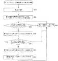
図4および図5は、プロセッサが新しいタスクに切り替えることを要求されるとき、プロセッサが優先度テーブル160、タスクフラグ165および他の情報を変える(あるいは変えない)方法の一例を説明する。この例の目的のために、複数のタスクフラグ165のうちの1つだけが1の値をもち、他のタスクフラグは0の値をもつことを仮定しなければならない。図4におけるステップの全てが、SPU108aのようなシングルプロセッサで実行されることが好ましい。 FIGS. 4 and 5 illustrate an example of how the processor may (or will not) change the priority table 160, task flag 165, and other information when the processor is required to switch to a new task. For the purposes of this example, it must be assumed that only one of the plurality of task flags 165 has a value of 1 and the other task flags have a value of 0. All of the steps in FIG. 4 are preferably performed on a single processor, such as
SPUが新しいタスクを実行するように指示されると、SPUは現タスクを処理しないようにまず自分自身をロックする(S10)。 When the SPU is instructed to execute a new task, the SPU first locks itself so as not to process the current task (S10).
次に、タスクが切り替えられようとしているSPU(以下、「切替プロセッサ」または「切替SPU」という)は、新しいタスクの優先度レベル([新優先度レベル])が優先度テーブル160において現在特定されるプロセッサ([テーブルプロセッサID])の優先度レベル([テーブル優先度レベル])にどのように関連しているかを判定するために必要な情報を集める(S12、S14)。 Next, for the SPU to which the task is to be switched (hereinafter referred to as “switching processor” or “switching SPU”), the priority level of the new task ([new priority level]) is currently identified in the priority table 160. The information necessary for determining how to relate to the priority level ([table priority level]) of the processor ([table processor ID]) is collected (S12, S14).
それから、切替SPUは、それ自身のタスクフラグ165が、当該SPUが最下位プロセッサであることを示しているかどうかを判定する(S16)。上記のように、1つの実施の形態において、このテストは、複数のタスクフラグ165のうちの1つだけが1の値をもつことが許される場合に、タスクフラグの値が1であるかどうかを判定することによって実行される。 The switching SPU then determines whether its own task flag 165 indicates that the SPU is the lowest processor (S16). As described above, in one embodiment, this test determines whether the value of the task flag is 1 if only one of the plurality of task flags 165 is allowed to have a value of 1. It is executed by determining.
切替プロセッサが最下位プロセッサ(以下、最下位プロセッサでないプロセッサを「通常プロセッサ」と呼ぶ)でないならば、切替プロセッサは新しいタスクの優先度([新優先度レベル])を優先度テーブルに現在リストされたタスクの優先度([テーブル優先度レベル])と比較する(S18)。 If the switching processor is not the lowest processor (hereinafter referred to as a "normal processor"), the switching processor is currently listed in the priority table with the priority of the new task ([New Priority Level]). The priority of the task ([table priority level]) is compared (S18).
通常プロセッサの新しい優先度レベルが優先度テーブルに格納された優先度レベルより大きいなら、通常プロセッサはロックを解除し(S24)、その新しいタスクを開始する(S26)。 If the new priority level of the normal processor is greater than the priority level stored in the priority table, the normal processor releases the lock (S24) and starts the new task (S26).
通常プロセッサの新しい優先度レベルが優先度テーブルに格納される優先度レベルより小さいなら、これは、通常プロセッサの新しいタスクが、その瞬間に、いろいろなプロセッサ(例えば複数のSPU108)の中でも最低優先度のタスクとなっている可能性があることを示している。したがって、通常プロセッサはそのIDと[新優先度レベル]を優先度テーブル160に格納する(S20、S22)。優先度テーブルを更新したあと、通常プロセッサはそれ自身のロックを解除し(S24)、その新しいタスクを開始する(S26)。 If the normal processor's new priority level is less than the priority level stored in the priority table, this means that the normal processor's new task is the lowest priority among the various processors (eg, multiple SPUs 108) at that moment. It is possible that it may be a task. Therefore, the normal processor stores the ID and [new priority level] in the priority table 160 (S20, S22). After updating the priority table, the normal processor releases its own lock (S24) and starts its new task (S26).
本発明の1つの態様によれば、通常プロセッサは、その新しいタスクが優先度テーブルにリストされたタスクより低い優先度をもっているという事実にもかかわらず、それ自身のタスクフラグや他のいずれのタスクフラグも変更せず、また、割り込み発生器のいずれのレジスタも変更しない。むしろ、それらの役目は、最下位プロセッサが最終的にタスクを切り替えるときに、その最下位プロセッサに実行が任される。この点に関していえば、任意の所与の瞬間において、最下位プロセッサは、必ずしも最下位優先順位タスクをもつプロセッサであるとは限らない。 In accordance with one aspect of the present invention, the normal processor has its own task flag or any other task, despite the fact that the new task has a lower priority than the tasks listed in the priority table. It does not change the flag, nor does it change any register of the interrupt generator. Rather, their role is left to execution by the lowest processor when the lowest processor eventually switches tasks. In this regard, at any given moment, the lowest processor is not necessarily the processor with the lowest priority task.
切替SPUが最下位プロセッサであるならば、SPUは新しいタスクの優先度([新優先度レベル])を優先度テーブルにリストされているタスクの優先度[テーブル優先度レベル]と比較する(S28)。 If the switching SPU is the lowest processor, the SPU compares the priority of the new task ([new priority level]) with the priority of the tasks listed in the priority table [table priority level] (S28). ).
最下位プロセッサの新しい優先度レベルが優先度テーブルに格納される優先度レベルより小さいなら、最下位プロセッサはそのIDと新しい優先度レベルを優先度テーブル160に保存する(S20、S22)。優先度テーブルを更新したあと、最下位プロセッサは、ロックを解除し(S24)、その新しいタスクを開始する(S26)。 If the new priority level of the lowest processor is smaller than the priority level stored in the priority table, the lowest processor stores the ID and the new priority level in the priority table 160 (S20, S22). After updating the priority table, the lowest processor releases the lock (S24) and starts the new task (S26).
しかし、最下位プロセッサの新しい優先度レベルが優先度テーブルに格納された優先度レベル以上であるならば、最下位プロセッサは、優先度テーブルが自分を指し示しているかどうかを判定する(S30)。言い換えると、この時点で、切替最下位プロセッサは、自分が最下位優先度のタスクをもっているプロセッサとして、優先度テーブルに現在リストされているかどうかを判定する。 However, if the new priority level of the lowest processor is equal to or higher than the priority level stored in the priority table, the lowest processor determines whether the priority table points to itself (S30). In other words, at this point, the switching lowest processor determines whether it is currently listed in the priority table as a processor with the lowest priority task.
優先度テーブルがこの時点で最下位プロセッサを指しているならば、最下位プロセッサは、優先度テーブルに含まれる優先度レベルをその新しいタスクと同じレベルに設定する(S22)。しかし、次の最下位プロセッサは現在の最下位プロセッサではないため、優先度テーブルを最下位プロセッサを指すように変えることはしない。 If the priority table indicates the lowest processor at this point, the lowest processor sets the priority level included in the priority table to the same level as the new task (S22). However, since the next lowest processor is not the current lowest processor, the priority table is not changed to point to the lowest processor.
優先度テーブルが最下位プロセッサを指しておらず、かつ、上述のように新しいタスクが優先度テーブルにリストされたタスクよりも重要であるならば、最下位プロセッサは、優先度テーブルにリストされたプロセッサのタスクフラグを1の値に設定する(このようにして、そのプロセッサは最下位プロセッサになる)(S34)。切替プロセッサは、次にそれ自身のタスクフラグを0に変える(このようにして、切替プロセッサは最下位プロセッサから通常プロセッサに変わる)(S36)。切替プロセッサ―それは最下位プロセッサであったが、現在は通常プロセッサである―は、自分自身のロックを解除し(S24)、新しいタスクを開始する(S26)。 If the priority table does not point to the lowest processor, and the new task is more important than the tasks listed in the priority table as described above, the lowest processor is listed in the priority table. The task flag of the processor is set to 1 (in this way, that processor becomes the lowest processor) (S34). The switching processor then changes its own task flag to 0 (in this way, the switching processor is changed from the lowest processor to the normal processor) (S36). The switching processor—it was the lowest processor but is now a normal processor—releases its own lock (S24) and starts a new task (S26).
このように、前述の動作によれば、どのプロセッサが最下位プロセッサに指定されるかを判定するのは、最下位プロセッサである。最下位プロセッサは、タスク切替の後も最下位プロセッサのままとどまることを決定するかもしれないし、あるいは、別の1つのプロセッサが最下位プロセッサになることを決定するかもしれない。さらに、通常プロセッサは、自分自身のタスクフラグや他のプロセッサのタスクフラグを変えることはせず、むしろ、それは最下位プロセッサの責任である。 Thus, according to the above-described operation, it is the lowest processor that determines which processor is designated as the lowest processor. The lowest processor may decide to remain the lowest processor after a task switch, or may decide that another one processor becomes the lowest processor. Furthermore, a normal processor does not change its own task flag or the task flags of other processors, but rather it is the responsibility of the lowest processor.
指定レジスタの実施例では、切替プロセッサは、もう一つのプロセッサを最下位プロセッサに指定する前、あるいは、指定した後に、指定レジスタ151も更新する。具体的には、切替プロセッサは、指定レジスタをその新しい最下位プロセッサを指す値に等しく設定する。前述の例では、指定レジスタは[テーブルプロセッサID]に設定されることになる(S32)。 In the designated register embodiment, the switching processor also updates the designated
図6は、1つのありうる動作を例示するものであり、割り込みが指定レジスタの実施例に従って処理される様子を示す。割り込みが起こるとき(S40)、割り込み生成器150は指定レジスタ151に格納される値をチェックすることによって最下位プロセッサを識別する(S42)。いったん最下位プロセッサが識別されると、IG150は最下位プロセッサに割り込みパケットを送る(S44)。 FIG. 6 illustrates one possible operation and illustrates how interrupts are handled according to an embodiment of a designated register. When an interrupt occurs (S40), the interrupt
図7は、1つのありうるオペレーションを例示するものであり、割り込みがポーリングレジスタの実施例に従って処理される様子を示す。割り込みが生じたとき(S50)、IG150は、割り込みがペンディングしていることを示すようにポーリングレジスタの値をセットする(S52)。たとえば、その値は、割り込みが処理を待っていることを示すフラグであってもよく、あるいは、特定のタイプの割り込みに割り当てられた数値であってもよい。もっとも、説明の目的のために、割り込みが処理を待ち構えているときはいつでも、ポーリングレジスタがその割り込みと関連づけられた割り込みパケットを指しているものと仮定する。 FIG. 7 illustrates one possible operation and illustrates how interrupts are handled according to an embodiment of a polling register. When an interrupt occurs (S50), the
最下位プロセッサがタイマ180(図1)から1ティック(時間の刻み)を受け取ると、最下位プロセッサは、ポーリングレジスタを見て割り込みパケットが存在するかどうかを調べるべきかどうか判定する(S54)。たとえば、特にプロセッサが通常10ミリ秒ごとしかタスクを切り替えないならば、最下位プロセッサは1ミリ秒ごとにポーリングレジスタを自動的にチェックすればよい。 When the lowest processor receives one tick (time step) from the timer 180 (FIG. 1), the lowest processor determines whether to check whether there is an interrupt packet by looking at the polling register (S54). For example, the lowest level processor may automatically check the polling register every 1 millisecond, especially if the processor normally switches tasks only every 10 milliseconds.
ポーリングレジスタがクリアになっているならば、最下位プロセッサと他のSPUは単に自分の現在のペンディング中のタスクを処理する(S64)。 If the polling register is cleared, the lowest processor and other SPUs simply process their current pending task (S64).
ポーリングレジスタがクリアされていないならば、最下位プロセッサは、ポーリングレジスタによって指定された割り込みパケットを用いて、どのタスクが割り込みに応答して実行されるべきかを判定する(S56〜S60)。最下位プロセッサはその後、そのレジスタをクリアする(S62)。 If the polling register is not cleared, the lowest processor uses the interrupt packet specified by the polling register to determine which task should be executed in response to the interrupt (S56 to S60). Thereafter, the lowest processor clears the register (S62).
最下位プロセッサまたは他のいずれかのプロセッサが、自分の現在のタスクから割り込みを処理するためのタスクに切り替える場合、図4と関連づけて上で述べたのと同じ動作を実行するのが好ましい。したがって、割込みハンドラタスクが、別の1つのプロセッサが処理しているタスクのうちの1つよりも高い優先度をもつならば、割込みを処理するプロセッサは優先度テーブルを変える。そのことが原因となって、タスク切り替えが起きたときに異なるプロセッサが最下位プロセッサになる。 When the lowest level processor or any other processor switches from its current task to a task for handling interrupts, it preferably performs the same operations as described above in connection with FIG. Thus, if an interrupt handler task has a higher priority than one of the tasks that another one processor is processing, the processor handling the interrupt changes the priority table. For this reason, a different processor becomes the lowest processor when task switching occurs.
したがって、本発明のある態様は、割り込みを処理するための次のプロセッサを識別する責任を、複数のプロセッサの集合の中の1つのプロセッサに割り当てることになる。そのプロセッサがタスクを切り替えて、タスク優先度に関する限り、自分はもはや最も重要度が低いプロセッサではないと判定したときはいつでも、そのプロセッサは、その割り込み関連の責任(すなわち、割り込みの処理および次の割り込みを処理するプロセッサの判定)を選択し、最も重要度が低いタスクを実行しているプロセッサに移す。その選択されたプロセッサは、タスク切り替えを経て、別の異なるプロセッサを選ぶまでは、割り込みを処理するように指定される。 Thus, certain aspects of the invention will assign responsibility for identifying the next processor to handle the interrupt to one processor in the set of processors. Whenever the processor switches tasks and determines that he is no longer the least important processor as far as task priority is concerned, the processor is responsible for its interrupt-related responsibilities (i.e. handling interrupts and Select the processor that will handle the interrupt), and move to the processor that is executing the task with the least importance. The selected processor is designated to handle interrupts until a different processor is selected after task switching.
上述の動作にしたがって、以下のエレメントは、システムの他のエレメントに対して以下のようにアクセスすることがある。最下位プロセッサは、少なくとも次のことができる。優先度テーブル160に対する読み書き、他の複数のSPU108のうちの1つのタスクフラグ165への書き込み、および割り込み生成器150の指定レジスタ151またはポーリングレジスタ152への書き込み。通常プロセッサは、少なくとも優先度テーブル160に対する読み書きをすることができる。IG150は、少なくとも次のことができる。指定レジスタの実施例において、最下位プロセッサへの情報の送信、指定レジスタの実施例において、指定レジスタ151からの読み出し、およびポーリングレジスタの実施例において、ポーリングレジスタ152への書き込み。 Following the above operations, the following elements may access other elements of the system as follows: The lowest level processor can at least: Reading from and writing to the priority table 160, writing to the task flag 165 of the other plurality of SPUs 108, and writing to the
本発明の利点の1つは、上述の構成要素例や動作に対する多種多様の代替手段に適応する能力があることである。 One advantage of the present invention is the ability to accommodate a wide variety of alternatives to the example components and operations described above.
たとえば、前述の議論の大部分においては、割り込みを処理し、どのプロセッサが次の割り込みを処理するかを管理することのできるプロセッサの例として、複数のSPUを用いた(そして、本発明は、上述のようなPE群に関連づけて用いられるときに特に有利である)が、本発明は他のプロセッサの集合にも適用することができる。たとえば、本発明は、各々のPEが、割り込みを処理するプロセッサの集合の中の1つのプロセッサとみなされる図2に示すようなシステムレベルに適用してもよい。 For example, in most of the above discussion, multiple SPUs were used as examples of processors that can handle interrupts and manage which processor handles the next interrupt (and the present invention Although particularly advantageous when used in connection with PE groups as described above), the present invention can also be applied to other sets of processors. For example, the present invention may be applied to a system level as shown in FIG. 2 where each PE is considered as one processor in the set of processors handling interrupts.
前述の議論は、各々のSPUが1つのタスクだけを実行すると仮定した。しかしながら、本発明は、自分自身でマルチタスクを実行する能力をもつSPUにも等しく適用することができる。もっとも、本発明は、そのようなSPUがこのマルチタスクの能力を発揮するためにマルチビットのタスクフラグをもつようなシステムにおいて好ましい。 The previous discussion assumed that each SPU performs only one task. However, the present invention is equally applicable to SPUs that have the ability to perform multitasking themselves. However, the present invention is preferable in a system in which such an SPU has a multi-bit task flag in order to exhibit the multi-task capability.
優先度テーブル160は、追加情報を格納するために用いてもよい。たとえば、優先度テーブルは次の情報列を格納してもよい。(1)SPUの識別情報、(2)SPUに割り当てたタスクの識別情報、および(3)そのタスクの優先順位の値。さらに、優先度テーブルは、SPU毎に一行の情報を格納してもよい。そのような優先度テーブルは、いろいろなSPUの全ての優先度のスナップショットを提供することができるという利点を有する。もっとも、そのような優先度テーブルが使われるとしても、最下位優先度値のタスクをもつSPUを早期に識別するための手段を提供することが好ましい。 The priority table 160 may be used to store additional information. For example, the priority table may store the following information sequence. (1) SPU identification information, (2) task identification information assigned to the SPU, and (3) priority value of the task. Furthermore, the priority table may store one line of information for each SPU. Such a priority table has the advantage that it can provide snapshots of all priorities of different SPUs. However, even if such a priority table is used, it is preferable to provide a means for early identification of an SPU having a task with the lowest priority value.
優先度テーブルは、優先度反転の問題を避けるために、追加情報を格納してもよい。優先度反転の問題は以下の場合に起こりうる。通常のプロセッサが、最下位プロセッサよりも低い新しいタスクを受け取る(そして、その通常のプロセッサが「次の最下位プロセッサ」になる)とき、次の最下位プロセッサが優先度テーブルを上書するとき、次の最下位プロセッサが最下位プロセッサよりも高い新しいタスクを受け取るとき、および最下位プロセッサがより高いタスクを受け取り、次の最下位プロセッサに切り替わるとき。もっとも、その次の最下位プロセッサは、もはや最下位タスクをもつプロセッサではない。これを扱うために、優先度テーブルは次の情報を格納してもよい。最も低いタスク優先度を反映している優先度レベル、最下位優先度タスクをもつプロセッサを識別するプロセッサID、最下位プロセッサの優先度を反映している現(Curr)優先度レベル、および最下位プロセッサを識別する現(Curr)プロセッサID(現優先度レベルと現プロセッサIDが現在のプロセッサID情報を指す場合において)。 The priority table may store additional information in order to avoid the problem of priority inversion. The problem of priority inversion can occur when: When a normal processor receives a new task lower than the lowest processor (and that normal processor becomes the “next lowest processor”), when the next lowest processor overwrites the priority table, When the next lowest processor receives a new task higher than the lowest processor, and when the lowest processor receives a higher task and switches to the next lowest processor. However, the next lowest processor is no longer the processor with the lowest task. In order to handle this, the priority table may store the following information: A priority level reflecting the lowest task priority, a processor ID identifying the processor having the lowest priority task, a current (Curr) priority level reflecting the priority of the lowest processor, and the lowest Current (Curr) processor ID that identifies the processor (when the current priority level and current processor ID point to current processor ID information).
さらに、指定レジスタの実施例とポーリングレジスタの実施例は、互いに相容れないというものではない。一例としてであるが、ある特定の割り込み情報は、指定レジスタの実施例に従って、SPUに直ちに送ることができるのに対して、ポーリングレジスタの実施例において、他の割り込み情報が最下位プロセッサによってポーリングできるように設けられてもよい。 Furthermore, the embodiment of the designation register and the embodiment of the polling register are not mutually exclusive. As an example, certain interrupt information can be sent immediately to the SPU according to the designated register embodiment, whereas in the polling register embodiment, other interrupt information can be polled by the lowest level processor. It may be provided as follows.
逆のことが明示されていない限り、「含む」、「たとえば」のような語句の使用は、「何ら限定することなく含む」ことを意味しており、一般的な記載を制限して、それが特定のもしくは類似した事項または事柄にすぐにでもつながるかのように解釈してはならない。「複数の」事物というときは、少なくとも2つの事物を意味しており、そうでないと明示されていない限り、「1つの」事物というときは、そのような事物を複数使う可能性を除外している。 Unless stated to the contrary, the use of words such as “including”, “for example”, means “including without limitation” and restricts the general description. Should not be interpreted as being immediately connected to a specific or similar matter or matter. Reference to “multiple” things means at least two things, and unless explicitly stated otherwise, “single” things exclude the possibility of using multiple such things. Yes.
前述の代替的な実施例の大部分は、互いに相容れないものではないが、特有の利点を成し遂げるために、いろいろな組合せで実行されてもよい。請求項により定義される本発明から逸脱することなく、上述の特徴のさまざまな変形や組み合わせを用いることができる。上記の実施の形態の記載は、請求項により定義される本発明を限定するものではなく、本発明を例示するものとして理解されるべきである。 Most of the alternative embodiments described above are not mutually exclusive, but may be implemented in various combinations to achieve specific advantages. Various modifications and combinations of the features described above can be used without departing from the invention as defined by the claims. The description of the above embodiments should not be construed as limiting the present invention defined by the claims, but should be understood as exemplifying the present invention.
100 プロセッサ要素、 102 I/Oインタフェース、 104 PU、 106 DMAC、 108 SPU、 110 メモリインタフェース、 130 メモリ、 150 割り込み生成器、 151 指定レジスタ、 152 ポーリングレジスタ、 160 優先度テーブル、 165 タスクフラグ、 170 デバイス、 180 タイマ。 100 processor elements, 102 I / O interface, 104 PU, 106 DMAC, 108 SPU, 110 memory interface, 130 memory, 150 interrupt generator, 151 designation register, 152 polling register, 160 priority table, 165 task flag, 170
Claims (14)
Translated fromJapaneseプロセッサ毎に指定値を格納しておき、前記指定値を参照して、各プロセッサが、自分が前記システムに対する割り込みを処理するために指定されたプロセッサであるかどうかを識別するステップと、
前記指定されたプロセッサが、他の複数のプロセッサの中で次に指定されるべきプロセッサを選択するステップとを含み、
前記指定されたプロセッサが自分自身とは異なるプロセッサを選択する場合、前記指定されたプロセッサは、前記選択されたプロセッサが前記指定されたプロセッサであることを示すように、自分自身の前記指定値と前記選択されたプロセッサの前記指定値とを変更することを特徴とする方法。A method of handling interrupts in a multiprocessor system,
Storing a designated value for each processor and referring to the designated value to identify whether each processor is a designated processor for handling an interrupt to the system;
The designated processor includes selecting a processor to be designated next among the plurality of other processors;
If the designated processor selects a different processor than itself, the designated processor is configured with its designated value to indicate that the selected processor is the designated processor. Changing the specified value of the selected processor.
前記選択するステップは、前記新しいタスクの優先度の値を前記優先度記憶場所に格納された優先度の値と比較するステップと、その比較結果にもとづいて、前記指定されたプロセッサか前記優先度記憶場所において特定されたプロセッサのどちらかを選択するステップとを含むことを特徴とする請求項1または2に記載の方法。A priority storage location is provided for storing a value identifying the processor having the lowest priority task and a priority value of the task;
The selecting step includes comparing a priority value of the new task with a priority value stored in the priority storage location, and based on a result of the comparison, the specified processor or the priority level. 3. A method according to claim 1 or 2, comprising the step of selecting either of the processors identified at the memory location.
割り込みが発生したとき、前記特定のプロセッサメモリの値にもとづいて、割り込み情報を前記指定されたプロセッサに転送するステップと、前記指定されたプロセッサが前記割り込みに応答してタスクを実行するステップとを含むことを特徴とする請求項1から3のいずれかに記載の方法。A specific processor memory is provided for storing a value identifying the designated processor, the method further comprising:
When an interrupt occurs, based on the value of the specific processor memory, transferring interrupt information to the designated processor; and executing the task in response to the interrupt by the designated processor. 4. A method according to any one of claims 1 to 3, comprising:
前記指定されたプロセッサが、割り込みが起きたかどうかを判定するために、ある時間間隔で前記ポーリングメモリを調べるステップと、前記指定されたプロセッサが、もし前記ポーリングメモリが割り込みが起きたことを示しているならば、割り込みに応答してタスクを実行するステップとを含むことを特徴とする請求項1から4のいずれかに記載の方法。A polling memory is provided for storing information indicating the presence of an interrupt, the method further comprising:
The designated processor examines the polling memory at certain time intervals to determine whether an interrupt has occurred; the designated processor indicates that the polling memory has been interrupted; And executing a task in response to an interrupt if any.
メモリが前記複数のプロセッサの内、どの1つのプロセッサが指定されたプロセッサであるかを示しており、前記指定されたプロセッサにおいて割り込みを処理するステップと、
前記指定されたプロセッサが、自分自身か前記複数のプロセッサのうちの別の1つのプロセッサを指定されたプロセッサとして選択するステップとを含み、
前記指定されたプロセッサが、前記複数のプロセッサのうちの別の1つのプロセッサが指定されたプロセッサになるべきであると判定するならば、前記指定されたプロセッサは、前記別の1つのプロセッサが指定されたプロセッサであることを示すように前記メモリを変更することを特徴とする方法。A method for handling an interrupt in a system including a plurality of processors, comprising:
A memory indicating which one of the plurality of processors is a designated processor, and handling an interrupt in the designated processor;
Said designated processor selecting itself or another one of said plurality of processors as a designated processor;
If the designated processor determines that another one of the plurality of processors should be the designated processor, the designated processor is designated by the other one processor. Changing the memory to indicate that the processor is a modified processor.
第1優先度レベルにおいて非割り込みタスクを処理する第1プロセッサと、
第2優先度レベルにおいて割り込みタスクを処理する第2プロセッサとを含み、
前記第1プロセッサは、前記第1優先度レベルが前記優先度テーブルに格納された優先度以下であるならば、前記第1優先度レベルとプロセッサの識別情報を前記優先度テーブルに書き込み、
前記第2プロセッサは、タスク切替時に、前記優先度テーブルにおいて、より低い優先度レベルをもつ別のプロセッサがあるかどうかを調べ、もし見つかった場合、前記第1プロセッサを指定してその後の割り込みの処理をさせることを特徴とするマルチプロセッサシステム。A priority table for storing processor identification information and priority identification information;
A first processor for processing non-interrupt tasks at a first priority level;
A second processor for handling interrupt tasks at a second priority level;
The first processor writes the first priority level and processor identification information to the priority table if the first priority level is less than or equal to the priority stored in the priority table;
When the task is switched, the second processor checks whether there is another processor having a lower priority level in the priority table, and if found, designates the first processor and specifies the subsequent interrupt. A multiprocessor system characterized by causing processing.
システムバスを介して通信する複数のプロセッサを設け、前記複数のプロセッサは複数の優先度レベルで複数のタスクを実行する機能を有し、前記複数のプロセッサの各々にはタスクメモリが関連づけられており、
複数のプロセッサ用の記憶領域をシステムメモリに設け、前記システムメモリは、前記システムバスを介して複数のプロセッサと情報のやりとりが可能であり、前記システムメモリは、前記複数のプロセッサと関連づけられた複数の優先度レベルの内、最下位優先度レベルを記憶するための記憶構造を有し、
前記記憶構造を介して、前記複数のプロセッサの内、最下位優先度レベルをもつ第1プロセッサを最下位優先度プロセッサとして指定し、
前記第1プロセッサが最下位優先度プロセッサとして指定されるように前記最下位優先度プロセッサの前記タスクメモリを設定し、
割り込み生成器の指定レジスタが前記最下位優先度プロセッサと関連づけられるように設定し、
前記割り込み生成器によって生成される第3タスクを直接、前記最下位優先度プロセッサに送り、
タスクが切り替えられるまでは、前記最下位優先度プロセッサにおいて前記第3タスクを処理し、タスク切り替えが起きた際、前記最下位優先度プロセッサにおいて、前記最下位優先度プロセッサが前記複数のプロセッサの中で最下位優先度レベルを依然としてもつかどうかを判定し、もしそうでないならば、前記複数のプロセッサの内、最下位優先度をもつ第2プロセッサが最下位優先度プロセッサとして指定されるように前記第2プロセッサのタスクメモリを設定することにより、前記第2プロセッサを前記最下位優先度プロセッサとして指定し、前記割り込み生成器の前記指定レジスタを前記第2プロセッサを指すように更新し、前記第1プロセッサの前記タスクメモリの設定を解除することを特徴とする方法。A method of handling interrupts in a multiprocessor system,
A plurality of processors that communicate via a system bus are provided, the plurality of processors have a function of executing a plurality of tasks at a plurality of priority levels, and a task memory is associated with each of the plurality of processors. ,
A storage area for a plurality of processors is provided in a system memory, the system memory can exchange information with a plurality of processors via the system bus, and the system memory is associated with the plurality of processors. A storage structure for storing the lowest priority level among the priority levels of
Via the storage structure, the first processor having the lowest priority level among the plurality of processors is designated as the lowest priority processor;
Setting the task memory of the lowest priority processor such that the first processor is designated as the lowest priority processor;
Set the interrupt generator's designated register to be associated with the lowest priority processor,
Send the third task generated by the interrupt generator directly to the lowest priority processor;
Until the task is switched, the third lowest priority processor processes the third task. When task switching occurs, the lowest priority processor includes the lowest priority processor among the plurality of processors. To determine whether the second processor having the lowest priority among the plurality of processors is designated as the lowest priority processor. By setting a task memory of the second processor, designating the second processor as the lowest priority processor, updating the designation register of the interrupt generator to point to the second processor, and A method of canceling the setting of the task memory of a processor.
前記ポーリングタイマによって設定されたポーリングタイムの期間において前記最下位優先度プロセッサが前記ポーリングレジスタをポーリングし、
前記最下位優先度プロセッサにおいて前記第4タスクが実行され、前記最下位優先度プロセッサによって前記ポーリングレジスタがクリアされることを特徴とする請求項8に記載の方法。A polling register and a polling timer are provided in the interrupt generator, and a fourth task is generated by the interrupt generator and stored in the polling register.
The lowest priority processor polls the polling register during a polling time period set by the polling timer;
9. The method of claim 8, wherein the fourth task is executed in the lowest priority processor and the polling register is cleared by the lowest priority processor.
システムバスを介して接続された複数のプロセッサを含み、各プロセッサは、第1タスクと第2タスクを実行するためのオペレーティングシステムカーネルを含み、各プロセッサは優先度レベルをもち、各プロセッサが前記複数のプロセッサの中で最下位優先度プロセッサであるかどうかを識別するためのタスクメモリが各プロセッサに関連づけられており、
前記システムバスを介して前記複数のプロセッサからアクセス可能なシステムメモリであって、少なくとも前記最下位優先度プロセッサおよび前記複数のプロセッサの最下位優先度レベルに関連づけられた記憶構造を有するシステムメモリと、前記最下位優先度プロセッサと関連づけられた指定レジスタを含む割り込み生成器とを含み、
前記割り込み生成器により生成された第3タスクが、実行のために前記システムバスを介して前記最下位優先度プロセッサに直接送られ、
前記第1タスクから前記第2タスクに切り替えるタスク切り替えの際に前記優先度の構造が更新され、
前記最下位優先度プロセッサが前記優先度の構造においてもはや最下位優先度ではないならば、前記最下位優先度プロセッサは、前記複数のプロセッサの中で第2プロセッサの前記関連づけられたタスクメモリを設定し、前記割り込み生成器の前記指定レジスタを更新し、前記最下位優先度プロセッサの前記関連づけられたタスクメモリの設定を解除することにより、前記第2プロセッサを第2の最下位優先度プロセッサとして指定することを特徴とするシステム。A distributed interrupt handling system,
A plurality of processors connected via a system bus, each processor including an operating system kernel for executing a first task and a second task, each processor having a priority level, and each processor having the plurality of processors Each processor has a task memory for identifying whether it is the lowest priority processor among the processors of
System memory accessible from the plurality of processors via the system bus, the system memory having a storage structure associated with at least the lowest priority processor and a lowest priority level of the plurality of processors; An interrupt generator including a designated register associated with the lowest priority processor;
A third task generated by the interrupt generator is sent directly to the lowest priority processor via the system bus for execution;
The priority structure is updated when the task is switched from the first task to the second task,
If the lowest priority processor is no longer the lowest priority in the priority structure, the lowest priority processor sets the associated task memory of a second processor among the plurality of processors. The second processor is designated as the second lowest priority processor by updating the designation register of the interrupt generator and releasing the setting of the associated task memory of the lowest priority processor. A system characterized by
Applications Claiming Priority (1)
| Application Number | Priority Date | Filing Date | Title |
|---|---|---|---|
| US64998405P | 2005-02-04 | 2005-02-04 |
Publications (1)
| Publication Number | Publication Date |
|---|---|
| JP2006216042Atrue JP2006216042A (en) | 2006-08-17 |
Family
ID=36777621
Family Applications (1)
| Application Number | Title | Priority Date | Filing Date |
|---|---|---|---|
| JP2006021904APendingJP2006216042A (en) | 2005-02-04 | 2006-01-31 | System and method for interruption processing |
Country Status (3)
| Country | Link |
|---|---|
| US (1) | US7350006B2 (en) |
| JP (1) | JP2006216042A (en) |
| WO (1) | WO2006082989A2 (en) |
Cited By (3)
| Publication number | Priority date | Publication date | Assignee | Title |
|---|---|---|---|---|
| WO2009122670A1 (en)* | 2008-04-03 | 2009-10-08 | パナソニック株式会社 | Multiprocessor system and multiprocessor system interrupt control method |
| US8417918B2 (en) | 2009-04-22 | 2013-04-09 | Samsung Electronics Co., Ltd. | Reconfigurable processor with designated processing elements and reserved portion of register file for interrupt processing |
| US9710409B2 (en) | 2013-05-28 | 2017-07-18 | Fujitsu Limited | Interrupt control apparatus and interrupt control method |
Families Citing this family (19)
| Publication number | Priority date | Publication date | Assignee | Title |
|---|---|---|---|---|
| US8984199B2 (en)* | 2003-07-31 | 2015-03-17 | Intel Corporation | Inter-processor interrupts |
| US20070124522A1 (en)* | 2005-11-30 | 2007-05-31 | Ellison Brandon J | Node detach in multi-node system |
| JP4441592B2 (en)* | 2006-02-16 | 2010-03-31 | セイコーエプソン株式会社 | Parallel processing apparatus and exclusive control method |
| JP5243711B2 (en)* | 2006-11-10 | 2013-07-24 | セイコーエプソン株式会社 | Processor |
| JP2008152470A (en)* | 2006-12-15 | 2008-07-03 | Hitachi Ltd | Data processing system and semiconductor integrated circuit |
| US7802042B2 (en)* | 2007-12-28 | 2010-09-21 | Intel Corporation | Method and system for handling a management interrupt event in a multi-processor computing device |
| US20090172232A1 (en)* | 2007-12-28 | 2009-07-02 | Zimmer Vincent J | Method and system for handling a management interrupt event |
| US8024504B2 (en)* | 2008-06-26 | 2011-09-20 | Microsoft Corporation | Processor interrupt determination |
| US20090327556A1 (en)* | 2008-06-27 | 2009-12-31 | Microsoft Corporation | Processor Interrupt Selection |
| JP4691153B2 (en)* | 2008-12-10 | 2011-06-01 | 富士通株式会社 | Multi-core processor, control method, and information processing apparatus |
| KR101610828B1 (en)* | 2009-09-23 | 2016-04-08 | 삼성전자주식회사 | Apparatus and method for managing interrupts On/Off for multi-core processor |
| US8407710B2 (en)* | 2010-10-14 | 2013-03-26 | International Business Machines Corporation | Systems and methods for dynamically scanning a plurality of active ports for priority schedule of work |
| US9946665B2 (en) | 2011-05-13 | 2018-04-17 | Melange Systems Private Limited | Fetch less instruction processing (FLIP) computer architecture for central processing units (CPU) |
| CN107544838B (en)* | 2016-06-24 | 2024-02-23 | 中兴通讯股份有限公司 | Interrupt processing method and device |
| JP6902948B2 (en)* | 2017-07-13 | 2021-07-14 | 日立Astemo株式会社 | Vehicle control device |
| CN111989652A (en)* | 2018-04-19 | 2020-11-24 | 三星电子株式会社 | Apparatus and method for deferred scheduling of tasks for operating systems on a multi-core processor |
| WO2020161924A1 (en)* | 2019-02-05 | 2020-08-13 | Nec Corporation | Sampling device |
| CN111143068B (en)* | 2019-12-27 | 2023-04-18 | 广东博智林机器人有限公司 | File operation method and device and embedded controller |
| CN116185915B (en)* | 2023-04-21 | 2023-08-04 | 山东云海国创云计算装备产业创新中心有限公司 | Bus scheduling method, device and equipment, medium and baseboard management control chip |
Citations (3)
| Publication number | Priority date | Publication date | Assignee | Title |
|---|---|---|---|---|
| JPH05204867A (en)* | 1992-01-28 | 1993-08-13 | Toshiba Corp | Timer Interrupt Control Method for Symmetric Multiprocessor System |
| JPH07160656A (en)* | 1993-12-13 | 1995-06-23 | Nippon Telegr & Teleph Corp <Ntt> | External interrupt control method |
| JP2005004562A (en)* | 2003-06-13 | 2005-01-06 | Canon Inc | Multiprocessor system, multiprocessor system control method, and multiprocessor system control program |
Family Cites Families (77)
| Publication number | Priority date | Publication date | Assignee | Title |
|---|---|---|---|---|
| DE2754890C2 (en) | 1977-12-09 | 1982-10-28 | Ibm Deutschland Gmbh, 7000 Stuttgart | Device for program interruption |
| US4574350A (en) | 1982-05-19 | 1986-03-04 | At&T Bell Laboratories | Shared resource locking apparatus |
| GB8329509D0 (en) | 1983-11-04 | 1983-12-07 | Inmos Ltd | Computer |
| US4636944A (en) | 1984-01-17 | 1987-01-13 | Concurrent Computer Corporation | Multi-level priority micro-interrupt controller |
| US4980820A (en) | 1985-02-28 | 1990-12-25 | International Business Machines Corporation | Interrupt driven prioritized queue |
| US4736318A (en) | 1985-03-01 | 1988-04-05 | Wang Laboratories, Inc. | Data processing system having tunable operating system means |
| US4987258A (en)* | 1985-03-29 | 1991-01-22 | Hoechst Aktiengesellschaft | 4,4'-diaminodiphenyl compounds, process for their preparation and their use |
| US4736319A (en) | 1985-05-15 | 1988-04-05 | International Business Machines Corp. | Interrupt mechanism for multiprocessing system having a plurality of interrupt lines in both a global bus and cell buses |
| US4716523A (en) | 1985-06-14 | 1987-12-29 | International Business Machines Corporation | Multiple port integrated DMA and interrupt controller and arbitrator |
| US4751634A (en) | 1985-06-14 | 1988-06-14 | International Business Machines Corporation | Multiple port communications adapter apparatus |
| US4954948A (en) | 1986-12-29 | 1990-09-04 | Motorola, Inc. | Microprocessor operating system for sequentially executing subtasks |
| US5109329A (en) | 1987-02-06 | 1992-04-28 | At&T Bell Laboratories | Multiprocessing method and arrangement |
| US5003466A (en) | 1987-02-06 | 1991-03-26 | At&T Bell Laboratories | Multiprocessing method and arrangement |
| US4901234A (en) | 1987-03-27 | 1990-02-13 | International Business Machines Corporation | Computer system having programmable DMA control |
| DE3882991T2 (en) | 1987-05-01 | 1994-03-24 | Digital Equipment Corp | ARRANGEMENT AND METHOD FOR OBTAINING INTERRUPTIONS WITH A "PENDED BUS". |
| GB8815042D0 (en) | 1988-06-24 | 1988-08-03 | Int Computers Ltd | Data processing apparatus |
| JPH0731613B2 (en) | 1988-07-16 | 1995-04-10 | 日本電気株式会社 | Diagnostic control device |
| US4987529A (en) | 1988-08-11 | 1991-01-22 | Ast Research, Inc. | Shared memory bus system for arbitrating access control among contending memory refresh circuits, peripheral controllers, and bus masters |
| US5212795A (en) | 1988-10-11 | 1993-05-18 | California Institute Of Technology | Programmable DMA controller |
| JP2712131B2 (en) | 1989-01-23 | 1998-02-10 | 株式会社日立製作所 | Communication control device |
| JPH03137757A (en) | 1989-10-24 | 1991-06-12 | Mitsubishi Electric Corp | Priority control method |
| US5974522A (en) | 1990-01-24 | 1999-10-26 | Cornell Research Foundation, Inc. | Machine for processing interrupted out-of-order instructions |
| US5247671A (en) | 1990-02-14 | 1993-09-21 | International Business Machines Corporation | Scalable schedules for serial communications controller in data processing systems |
| US5452452A (en)* | 1990-06-11 | 1995-09-19 | Cray Research, Inc. | System having integrated dispatcher for self scheduling processors to execute multiple types of processes |
| US5613128A (en)* | 1990-12-21 | 1997-03-18 | Intel Corporation | Programmable multi-processor interrupt controller system with a processor integrated local interrupt controller |
| JP2855298B2 (en) | 1990-12-21 | 1999-02-10 | インテル・コーポレーション | Arbitration method of interrupt request and multiprocessor system |
| EP0577614B1 (en) | 1991-03-28 | 1995-10-04 | Cray Research, Inc. | Real-time i/o operation in a vector processing computer system |
| US5291609A (en) | 1991-06-13 | 1994-03-01 | Sony Electronics Inc. | Computer interface circuit |
| US5469571A (en) | 1991-07-15 | 1995-11-21 | Lynx Real-Time Systems, Inc. | Operating system architecture using multiple priority light weight kernel task based interrupt handling |
| US5379381A (en) | 1991-08-12 | 1995-01-03 | Stratus Computer, Inc. | System using separate transfer circuits for performing different transfer operations respectively and scanning I/O devices status upon absence of both operations |
| US5257375A (en) | 1991-08-23 | 1993-10-26 | International Business Machines Corp. | Method and apparatus for dispatching tasks requiring short-duration processor affinity |
| EP0535821B1 (en)* | 1991-09-27 | 1997-11-26 | Sun Microsystems, Inc. | Method and apparatus for dynamically steering undirected interrupts |
| US5590380A (en) | 1992-04-22 | 1996-12-31 | Kabushiki Kaisha Toshiba | Multiprocessor system with processor arbitration and priority level setting by the selected processor |
| US5515538A (en) | 1992-05-29 | 1996-05-07 | Sun Microsystems, Inc. | Apparatus and method for interrupt handling in a multi-threaded operating system kernel |
| EP0602858A1 (en) | 1992-12-18 | 1994-06-22 | International Business Machines Corporation | Apparatus and method for servicing interrupts in a multiprocessor system |
| CA2123447C (en)* | 1993-09-20 | 1999-02-16 | Richard L. Arndt | Scalable system interrupt structure for a multiprocessing system |
| US5555383A (en) | 1994-11-07 | 1996-09-10 | International Business Machines Corporation | Peripheral component interconnect bus system having latency and shadow timers |
| US5881313A (en) | 1994-11-07 | 1999-03-09 | Digital Equipment Corporation | Arbitration system based on requester class and relative priority including transmit descriptor valid bit for a shared resource having multiple requesters |
| US5553293A (en) | 1994-12-09 | 1996-09-03 | International Business Machines Corporation | Interprocessor interrupt processing system |
| US5768599A (en) | 1995-02-28 | 1998-06-16 | Nec Corporation | Interrupt managing system for real-time operating system |
| US5777629A (en) | 1995-03-24 | 1998-07-07 | 3Dlabs Inc. Ltd. | Graphics subsystem with smart direct-memory-access operation |
| US5564027A (en) | 1995-04-20 | 1996-10-08 | International Business Machines Corporation | Low latency cadence selectable interface for data transfers between busses of differing frequencies |
| US5671365A (en) | 1995-10-20 | 1997-09-23 | Symbios Logic Inc. | I/O system for reducing main processor overhead in initiating I/O requests and servicing I/O completion events |
| US5606703A (en) | 1995-12-06 | 1997-02-25 | International Business Machines Corporation | Interrupt protocol system and method using priority-arranged queues of interrupt status block control data structures |
| US5892956A (en)* | 1995-12-19 | 1999-04-06 | Advanced Micro Devices, Inc. | Serial bus for transmitting interrupt information in a multiprocessing system |
| US5822595A (en) | 1995-12-29 | 1998-10-13 | Intel Corporation | Method and apparatus for providing an interrupt handler employing a token window scheme |
| US5794072A (en) | 1996-05-23 | 1998-08-11 | Vlsi Technology, Inc. | Timing method and apparatus for interleaving PIO and DMA data transfers |
| DE19629855C1 (en)* | 1996-07-24 | 1997-12-11 | Daimler Benz Ag | Device for fastening an injector holder |
| US5995745A (en) | 1996-12-23 | 1999-11-30 | Yodaiken; Victor J. | Adding real-time support to general purpose operating systems |
| US5907712A (en) | 1997-05-30 | 1999-05-25 | International Business Machines Corporation | Method for reducing processor interrupt processing time by transferring predetermined interrupt status to a system memory for eliminating PIO reads from the interrupt handler |
| JP3699806B2 (en) | 1997-06-20 | 2005-09-28 | 株式会社東芝 | Interrupt controller and control system |
| US5966543A (en) | 1997-06-26 | 1999-10-12 | International Business Machines Corporation | Method of using collaborative spinlocks to provide exclusive access to a resource in a multiprocessor computer system |
| US6385638B1 (en) | 1997-09-04 | 2002-05-07 | Equator Technologies, Inc. | Processor resource distributor and method |
| US5944800A (en) | 1997-09-12 | 1999-08-31 | Infineon Technologies Corporation | Direct memory access unit having a definable plurality of transfer channels |
| US6418496B2 (en)* | 1997-12-10 | 2002-07-09 | Intel Corporation | System and apparatus including lowest priority logic to select a processor to receive an interrupt message |
| US6219741B1 (en) | 1997-12-10 | 2001-04-17 | Intel Corporation | Transactions supporting interrupt destination redirection and level triggered interrupt semantics |
| US6647431B1 (en) | 1997-12-31 | 2003-11-11 | Nortel Networks Limited | Method and apparatus for handling I/O messages |
| US6473780B1 (en) | 1998-04-01 | 2002-10-29 | Intel Corporation | Scheduling of direct memory access |
| US6289369B1 (en) | 1998-08-25 | 2001-09-11 | International Business Machines Corporation | Affinity, locality, and load balancing in scheduling user program-level threads for execution by a computer system |
| US6148361A (en) | 1998-12-17 | 2000-11-14 | International Business Machines Corporation | Interrupt architecture for a non-uniform memory access (NUMA) data processing system |
| US6275749B1 (en) | 1998-12-22 | 2001-08-14 | Philips Electronics North America Corporation | Interrupt-controlled thread processing |
| US6347349B1 (en) | 1998-12-28 | 2002-02-12 | International Business Machines Corp. | System for determining whether a subsequent transaction may be allowed or must be allowed or must not be allowed to bypass a preceding transaction |
| US6633942B1 (en) | 1999-08-12 | 2003-10-14 | Rockwell Automation Technologies, Inc. | Distributed real-time operating system providing integrated interrupt management |
| US6490642B1 (en) | 1999-08-12 | 2002-12-03 | Mips Technologies, Inc. | Locked read/write on separate address/data bus using write barrier |
| US6430643B1 (en)* | 1999-09-02 | 2002-08-06 | International Business Machines Corporation | Method and system for assigning interrupts among multiple interrupt presentation controllers |
| US6379381B1 (en)* | 1999-09-03 | 2002-04-30 | Advanced Cardiovascular Systems, Inc. | Porous prosthesis and a method of depositing substances into the pores |
| US6701405B1 (en) | 1999-10-01 | 2004-03-02 | Hitachi, Ltd. | DMA handshake protocol |
| US6629252B1 (en) | 1999-10-28 | 2003-09-30 | International Business Machines Corporation | Method for determining if a delay required before proceeding with the detected interrupt and exiting the interrupt without clearing the interrupt |
| US6606676B1 (en) | 1999-11-08 | 2003-08-12 | International Business Machines Corporation | Method and apparatus to distribute interrupts to multiple interrupt handlers in a distributed symmetric multiprocessor system |
| US6601120B1 (en) | 2000-07-13 | 2003-07-29 | Silicon Graphics, Inc. | System, method and computer program product for implementing scalable multi-reader/single-writer locks |
| US6920516B2 (en)* | 2000-08-31 | 2005-07-19 | Hewlett-Packard Development Company, L.P. | Anti-starvation interrupt protocol |
| US6665760B1 (en) | 2000-09-29 | 2003-12-16 | Rockwell Automation Technologies, Inc. | Group shifting and level shifting rotational arbiter system |
| US6813665B2 (en)* | 2001-09-21 | 2004-11-02 | Intel Corporation | Interrupt method, system and medium |
| JP2005165508A (en) | 2003-12-01 | 2005-06-23 | Renesas Technology Corp | Direct memory access controller |
| US7680972B2 (en)* | 2005-02-04 | 2010-03-16 | Sony Computer Entertainment Inc. | Micro interrupt handler |
| JP4668645B2 (en) | 2005-02-24 | 2011-04-13 | パナソニック株式会社 | DMA controller and data transfer control method |
| JP2007160656A (en) | 2005-12-13 | 2007-06-28 | Nippon Seiki Co Ltd | Led printing head |
- 2006
- 2006-01-31JPJP2006021904Apatent/JP2006216042A/enactivePending
- 2006-02-01WOPCT/JP2006/302100patent/WO2006082989A2/ennot_activeApplication Discontinuation
- 2006-02-03USUS11/346,947patent/US7350006B2/enactiveActive
Patent Citations (3)
| Publication number | Priority date | Publication date | Assignee | Title |
|---|---|---|---|---|
| JPH05204867A (en)* | 1992-01-28 | 1993-08-13 | Toshiba Corp | Timer Interrupt Control Method for Symmetric Multiprocessor System |
| JPH07160656A (en)* | 1993-12-13 | 1995-06-23 | Nippon Telegr & Teleph Corp <Ntt> | External interrupt control method |
| JP2005004562A (en)* | 2003-06-13 | 2005-01-06 | Canon Inc | Multiprocessor system, multiprocessor system control method, and multiprocessor system control program |
Cited By (4)
| Publication number | Priority date | Publication date | Assignee | Title |
|---|---|---|---|---|
| WO2009122670A1 (en)* | 2008-04-03 | 2009-10-08 | パナソニック株式会社 | Multiprocessor system and multiprocessor system interrupt control method |
| JP2009251802A (en)* | 2008-04-03 | 2009-10-29 | Panasonic Corp | Multiprocessor system and multiprocessor system interrupt control method |
| US8417918B2 (en) | 2009-04-22 | 2013-04-09 | Samsung Electronics Co., Ltd. | Reconfigurable processor with designated processing elements and reserved portion of register file for interrupt processing |
| US9710409B2 (en) | 2013-05-28 | 2017-07-18 | Fujitsu Limited | Interrupt control apparatus and interrupt control method |
Also Published As
| Publication number | Publication date |
|---|---|
| US7350006B2 (en) | 2008-03-25 |
| US20060200610A1 (en) | 2006-09-07 |
| WO2006082989A3 (en) | 2007-08-16 |
| WO2006082989A2 (en) | 2006-08-10 |
Similar Documents
| Publication | Publication Date | Title |
|---|---|---|
| JP2006216042A (en) | System and method for interruption processing | |
| KR100457146B1 (en) | Interrupt architecture for a non-uniform memory access data processing system | |
| US8209690B2 (en) | System and method for thread handling in multithreaded parallel computing of nested threads | |
| US7194568B2 (en) | System and method for dynamic mirror-bank addressing | |
| JPH02236735A (en) | Data processing method and apparatus | |
| JP4364202B2 (en) | Data processing method and data processing system | |
| JP2001142842A (en) | DMA handshake protocol | |
| US12164956B2 (en) | Thread scheduling for multithreaded data processing environments | |
| KR20070093439A (en) | Systems, methods, processes, and apparatus for cache coherency in cache locations of different lengths | |
| JP2007133456A (en) | Semiconductor device | |
| US9779044B2 (en) | Access extent monitoring for data transfer reduction | |
| US7590686B2 (en) | Apparatus for controlling a multi-processor system, scalable node, scalable multi-processor system, and method of controlling a multi-processor system | |
| US6708259B1 (en) | Programmable wake up of memory transfer controllers in a memory transfer engine | |
| JPWO2010122607A1 (en) | Storage control device and control method thereof | |
| JP2580525B2 (en) | Load balancing method for parallel computers | |
| JP2009515280A (en) | Centralized interrupt controller | |
| JP2000235503A (en) | Operating system and computer | |
| JP2847729B2 (en) | Information processing device | |
| JP2972557B2 (en) | Data transfer control device and control method | |
| CN118093152A (en) | Multi-core system information scheduling method and device, electronic equipment and storage medium | |
| JP2505021B2 (en) | Main memory controller | |
| JP2001236238A (en) | Interrupt processing method | |
| JPH056333A (en) | Multiprocessor system | |
| JPH0535507A (en) | Central processing unit | |
| JP2001290664A (en) | Multi-task control processor system |
Legal Events
| Date | Code | Title | Description |
|---|---|---|---|
| A977 | Report on retrieval | Free format text:JAPANESE INTERMEDIATE CODE: A971007 Effective date:20071004 | |
| A131 | Notification of reasons for refusal | Free format text:JAPANESE INTERMEDIATE CODE: A131 Effective date:20071009 | |
| A521 | Request for written amendment filed | Free format text:JAPANESE INTERMEDIATE CODE: A523 Effective date:20071203 | |
| A02 | Decision of refusal | Free format text:JAPANESE INTERMEDIATE CODE: A02 Effective date:20080520 |