JP2006211317A - Bone conduction speaker - Google Patents
Bone conduction speakerDownload PDFInfo
- Publication number
- JP2006211317A JP2006211317AJP2005020993AJP2005020993AJP2006211317AJP 2006211317 AJP2006211317 AJP 2006211317AJP 2005020993 AJP2005020993 AJP 2005020993AJP 2005020993 AJP2005020993 AJP 2005020993AJP 2006211317 AJP2006211317 AJP 2006211317A
- Authority
- JP
- Japan
- Prior art keywords
- bone conduction
- piezoelectric element
- conduction speaker
- displacement
- sound
- Prior art date
- Legal status (The legal status is an assumption and is not a legal conclusion. Google has not performed a legal analysis and makes no representation as to the accuracy of the status listed.)
- Granted
Links
Images

Landscapes
- Details Of Audible-Bandwidth Transducers (AREA)
- Piezo-Electric Transducers For Audible Bands (AREA)
Abstract
Translated fromJapaneseDescription
Translated fromJapanese本発明は、主として音響振動発生用圧電素子としての積層型圧電素子を備えると共に、骨伝導音以外に気導音についても良好に聴取可能な構造を持つ骨伝導スピーカに関する。 The present invention relates to a bone conduction speaker that mainly includes a laminated piezoelectric element as a piezoelectric element for generating acoustic vibrations and has a structure capable of satisfactorily hearing air conduction sound in addition to bone conduction sound.
従来、骨伝導スピーカは、その目的として音響性能については言うまでもなく、通常人体の頭部に固定して使用するものであるため、装着性を考えた場合に小型であることや軽量であることが望まれ、しかも多くの場合には携帯可能な要求もあることにより電力消費が少ないこと等も望まれている。 Conventionally, bone conduction speakers are usually used by being fixed to the head of a human body, not to mention acoustic performance, so that they may be small or light when considering wearability. In addition, in many cases, there is also a demand for portability, so that it is also desired that power consumption is low.
このような骨伝導スピーカにおいて、一般的に用いられているのは電磁型タイプのものであるが、それは原理的に往年の電話機における受話器の振動板のみを小さくした構造であると考えれば分かり易いもので、具体的には振動用の鉄片(プレートヨーク)がばね機構を介して永久磁石で励磁されたヨークと向かい合った構造となっている。この構造の場合、音声信号レベルに比例する電流がプレートヨークの周りに置かれた巻き線に流れると、鉄片に音声信号レベルに比例した力が作用して鉄片が振動し、その振動の反作用で音声信号レベルに比例した力で音響振動が接触する物体に伝播する。 In such a bone conduction speaker, an electromagnetic type is generally used, but it is easy to understand if it is in principle a structure in which only the diaphragm of the handset in the telephone of the past year is made small. Specifically, the structure has a structure in which a vibrating iron piece (plate yoke) faces a yoke excited by a permanent magnet via a spring mechanism. In this structure, when a current proportional to the audio signal level flows through a winding placed around the plate yoke, a force proportional to the audio signal level acts on the iron piece, causing the iron piece to vibrate. The acoustic vibration propagates to the contacting object with a force proportional to the sound signal level.
電磁型タイプの骨伝導スピーカでは、全ての構成部材が金属のために堅牢であるが、その反面として、重量を低減化させるには限界があるし、その他の短所として、駆動特性のリニヤ性を確保するために磁気コイルには一定の奥行きが必要になり、そのためにデバイスの厚みが必要となってしまうことや、電磁力を振動の駆動源としていることにより巻き線に流れる電流がジュール熱を発生してエネルギー損失を生ずるが、これが音響出力に何等寄与しないエネルギー損失となってしまうこと等が挙げられる。 In the electromagnetic type bone conduction speaker, all the structural members are solid because of the metal, but on the other hand, there is a limit to reducing the weight, and as another disadvantage, the linearity of the drive characteristics is reduced. In order to ensure this, the magnetic coil needs to have a certain depth, which requires the thickness of the device, and because the electromagnetic force is used as the vibration drive source, the current flowing in the winding generates Joule heat. It is generated and causes energy loss, which may be energy loss that does not contribute to the sound output.
そこで、最近では超磁歪材料を応用した骨伝導スピーカ(特許文献1参照)も提案されている。この骨伝導スピーカの場合、基本的には磁性材料であるコアに対してコイルに流れる音声電流で励磁することにより超磁歪材料の発生する歪を駆動源とする圧電型タイプ(圧電方式)のものであるが、コイルに電流を流す必要がある点で電磁型タイプ(電磁方式)のものと共通してエネルギー損失面での問題があるものの、その利点として、駆動に関してエネルギー効率が電磁型タイプのものと比べると著しく高いことが挙げられる。 Therefore, recently, a bone conduction speaker using a giant magnetostrictive material (see Patent Document 1) has also been proposed. In the case of this bone conduction speaker, a piezoelectric type (piezoelectric method) that uses a distortion generated by a giant magnetostrictive material as a drive source by exciting a core made of a magnetic material with an audio current flowing in the coil. However, there is a problem in terms of energy loss in common with the electromagnetic type (electromagnetic method) in that it is necessary to pass current through the coil. It can be mentioned that it is significantly higher than the product.
即ち、電磁型タイプの場合には電磁力を振動の駆動源とするものであり、上述した通りに巻線でジュール熱が発生してしまうが、圧電型タイプのものではこれに対応するエネルギー損失が伴わず、しかも圧電振動子のエネルギー密度が電磁型タイプのものと較べて高く、原理的に小型化に有利なものとなっている。但し、圧電型タイプの場合、電磁型タイプと比べると駆動電圧が高く、携帯機器等への応用分野では内蔵する電池の電圧以上の電圧を必要とするために昇圧が必要となる場合があり、この昇圧回路でのエネルギー損失も無視できないために既存の圧電材料が持つ実性能では必ずしも省エネネルギー化を図る面で観れば電磁型タイプのものと比べて圧倒的に有利と言えない面もあるが、それにも拘らず駆動電圧の高さの問題については昨今の積層型圧電アクチュエータや積層セラミックコンデンサに用いられている積層技術を活用することにより解消されつつあり、昨今では駆動電圧を十分に低下させられるようになっている。 That is, in the case of the electromagnetic type, the electromagnetic force is used as a driving source of vibration, and Joule heat is generated in the winding as described above. In the case of the piezoelectric type, the energy loss corresponding to this is generated. In addition, the energy density of the piezoelectric vibrator is higher than that of the electromagnetic type, which is in principle advantageous for downsizing. However, in the case of the piezoelectric type, the driving voltage is higher than that of the electromagnetic type, and in an application field for portable devices, etc., a voltage higher than the voltage of the built-in battery may be required, so that boosting may be required. Since the energy loss in this booster circuit cannot be ignored, the actual performance of existing piezoelectric materials is not necessarily overwhelmingly advantageous compared to the electromagnetic type in terms of energy saving. Nevertheless, the problem of high drive voltage is being resolved by utilizing the multilayer technology used in recent multilayer piezoelectric actuators and multilayer ceramic capacitors. Nowadays, the drive voltage is sufficiently reduced. It is supposed to be.
例えば積層型圧電アクチュエータについては、圧電セラミックスの粉末に有機バインダを混入して成膜されたシートに銀−パラジュームの電極層を印刷して積層した後、一体化焼結することにより製造される素子が開発されており、幅広い応用が展開されている。この積層型圧電アクチュエータの場合、積層された薄いシートの一層毎に電圧を印加できるために比較的低電圧でも大きな電界を印加することができ、しかも各々層で発生する歪が厚み方向に加算されるため、圧電定数dを見掛け上で積層数倍に拡大したものと同じにすることができる。 For example, for a laminated piezoelectric actuator, an element produced by integrally sintering after printing a silver-palladium electrode layer on a sheet formed by mixing an organic binder with a piezoelectric ceramic powder. Has been developed and has a wide range of applications. In the case of this laminated piezoelectric actuator, since a voltage can be applied to each layer of laminated thin sheets, a large electric field can be applied even at a relatively low voltage, and the strain generated in each layer is added in the thickness direction. Therefore, the piezoelectric constant d can be apparently the same as the number of layers multiplied by several times.
ところで、骨伝導スピーカについては、一般的に人体の頭部における外耳周辺に一定の圧力で固定して使用されるが、特許文献1のイヤフォン、音声伝達装置の場合には外耳道に挿入する形態の圧電型タイプのものを提案しており、極めて簡素な構成で省電力化(省エネルギー化)が図られ、且つ軽量な携帯機器に適した構造となっている。尚、その他の骨伝導スピーカに係る周知技術としては、骨伝導ピックアップを外耳道に挿入する形態のもの(特許文献2参照)もある。 By the way, the bone conduction speaker is generally used by being fixed with a constant pressure around the outer ear in the head of the human body. However, in the case of the earphone and the sound transmission device of Patent Document 1, it is inserted into the ear canal. A piezoelectric type has been proposed, which has an extremely simple configuration that saves power (energy saving) and is suitable for a lightweight portable device. In addition, as another known technique related to the bone conduction speaker, there is a technique in which a bone conduction pickup is inserted into the ear canal (see Patent Document 2).
上述した特許文献1や特許文献2係る骨伝導スピーカの場合、外耳道に挿入するタイプであることにより、頭部に固定して使用する場合のように一定の接触圧力を加えるために必要とされるヘッドセット等の付属器具を不要にでき、小型化や省電力化を十分に図り得て携帯機器への適用性に優れた構造となるという利点があるが、その反面、例えばイヤフォンの形態で外耳道に挿入する形態としただけでは、骨伝導方式のもう一つの利点である骨伝導音を気導音と合わせて聴取する機能を失ってしまうという大きな問題がある。 In the case of the bone conduction speakers according to Patent Document 1 and
本発明は、このような問題点を解決すべくなされたもので、その技術的課題は、小型で軽量にして省電力化を図り得ると共に、骨伝導音以外の気導音も良好に聴取可能な装着性に優れた構造の骨伝導スピーカを提供することにある。 The present invention has been made to solve such problems, and its technical problem is that it can be made compact and lightweight to save power, and air conduction sound other than bone conduction sound can be heard well. An object of the present invention is to provide a bone conduction speaker having a structure excellent in wearability.
本発明によれば、音響振動発生用圧電素子としての積層型圧電素子と、積層型圧電素子における長さ方向の変位を拡大するための変位拡大機構と、変位拡大機構を介して積層型圧電素子を実装するための弾性体とを備え、更に、積層型圧電素子及び変位拡大機構を実装した弾性体を外耳道へ挿入する形態で使用に供される骨伝導スピーカが得られる。 According to the present invention, a laminated piezoelectric element as a piezoelectric element for generating acoustic vibration, a displacement enlarging mechanism for enlarging a displacement in the length direction of the laminated piezoelectric element, and a laminated piezoelectric element via the displacement enlarging mechanism And a bone conduction speaker for use in a form in which an elastic body mounted with a laminated piezoelectric element and a displacement enlarging mechanism is inserted into the external auditory canal.
又、本発明によれば、上記骨伝導スピーカにおいて、弾性体は、貫通穴を有する容器であって、該貫通穴内に変位拡大機構を介して積層型圧電素子を実装可能であると共に、実装状態で骨伝導音以外の気導音についても聴取可能であるように該積層型圧電素子と該貫通穴との間に隙間を持たせた構造である骨伝導スピーカが得られる。この骨伝導スピーカにおいて、容器は円筒形であることが好ましい。 Further, according to the present invention, in the bone conduction speaker, the elastic body is a container having a through hole, and the stacked piezoelectric element can be mounted in the through hole via a displacement enlarging mechanism, and the mounted state Thus, a bone conduction speaker having a structure in which a gap is provided between the laminated piezoelectric element and the through hole so that air conduction sound other than bone conduction sound can be heard can be obtained. In this bone conduction speaker, the container is preferably cylindrical.
更に、本発明によれば、上記何れか一つの骨伝導スピーカにおいて、積層型圧電素子を駆動して音響振動発生させるための駆動信号は、音声信号源から得られる音声信号に一定の直流バイアス電圧を印加して生成されたものである骨伝導スピーカが得られる。 Furthermore, according to the present invention, in any one of the above bone conduction speakers, the driving signal for driving the laminated piezoelectric element to generate acoustic vibration is a constant DC bias voltage applied to the audio signal obtained from the audio signal source. A bone-conduction speaker that is generated by applying the is obtained.
本発明の骨伝導スピーカの場合、音響振動発生用圧電素子としての積層型圧電素子をその長さ方向の変位を拡大するための籠状の変位拡大機構を介して弾性体による貫通穴を有する円筒形の容器の貫通穴内に実装すると共に、実装状態で骨伝導音以外の気導音についても聴取可能であるように積層型圧電素子と貫通穴との間に隙間を持たせた構造として外耳道に挿入して使用する形態とし、更に、積層型圧電素子を駆動して音響振動発生させるための駆動信号として、音声信号源から得られる音声信号に一定の直流バイアス電圧を印加して生成されたものを用いるようにしているので、積層型圧電素子における体積を増大させたり、或いは振動発生力を低減させること無しに振動発生力の周波数特性を制御可能となり、結果として、小型で軽量にして省電力化を図り得ると共に、骨伝導音以外の気導音も良好に聴取可能な装着性に優れた構造が得られるようになる。 In the case of the bone conduction speaker of the present invention, a laminated piezoelectric element as a piezoelectric element for generating acoustic vibrations is a cylinder having a through hole made of an elastic body through a hook-like displacement enlarging mechanism for enlarging the displacement in the length direction. In the external auditory canal as a structure with a gap between the laminated piezoelectric element and the through hole so that air conduction sound other than bone conduction sound can be heard in the mounted state while being mounted in the through hole of the shaped container It is generated by inserting a constant DC bias voltage to the audio signal obtained from the audio signal source as a drive signal for driving the laminated piezoelectric element to generate acoustic vibrations. Therefore, it is possible to control the frequency characteristics of the vibration generating force without increasing the volume in the multilayer piezoelectric element or reducing the vibration generating force. A manner with obtaining realizing power saving, so that superior structural air conduction sound even better audible wearability other than bone conduction sound can be obtained.
本発明の最良の形態に係る骨伝導スピーカは、音響振動発生用圧電素子としての積層型圧電素子と、積層型圧電素子における長さ方向の変位を拡大するための変位拡大機構と、変位拡大機構を介して積層型圧電素子を実装するための弾性体とを備えると共に、積層型圧電素子及び変位拡大機構を実装した弾性体を外耳道へ挿入する形態で使用に供されるものである。但し、ここでの弾性体は、貫通穴を有する容器であって、貫通穴内に変位拡大機構を介して積層型圧電素子を実装可能であると共に、実装状態で骨伝導音以外の気導音についても聴取可能であるように積層型圧電素子と貫通穴との間に隙間を持たせた構造のものとなっている。尚、容器は円筒形であることが最も好ましい。又、この骨伝導スピーカでは、積層型圧電素子を駆動して音響振動発生させるための駆動信号として、音声信号源から得られる音声信号に一定の直流バイアス電圧を印加して生成されたものを用いる。 A bone conduction speaker according to the best mode of the present invention includes a laminated piezoelectric element as a piezoelectric element for generating acoustic vibration, a displacement enlarging mechanism for enlarging a displacement in the length direction of the laminated piezoelectric element, and a displacement enlarging mechanism. And an elastic body for mounting the laminated piezoelectric element via the elastic body, and the elastic body on which the laminated piezoelectric element and the displacement enlarging mechanism are mounted is inserted into the ear canal. However, the elastic body here is a container having a through hole, and a laminated piezoelectric element can be mounted in the through hole via a displacement magnifying mechanism, and air conduction sound other than bone conduction sound in the mounted state. As a result, the gap between the multilayer piezoelectric element and the through hole is provided. The container is most preferably cylindrical. In this bone conduction speaker, a drive signal generated by applying a constant DC bias voltage to an audio signal obtained from an audio signal source is used as a drive signal for driving a laminated piezoelectric element to generate acoustic vibrations. .
即ち、このような骨伝導スピーカでは、積層型圧電素子の長さ方向の変位を拡大する変位拡大機構を弾性体による貫通穴を有する円筒形の容器の貫通穴内に実装すると共に、実装状態で骨伝導音以外の気導音についても聴取可能であるように積層型圧電素子と貫通穴との間に隙間を持たせた基本構造を持ち、音声信号源からの音声信号に一定の直流バイアス電圧を印加して生成した駆動信号を用いて積層型圧電素子を駆動するようにしているため、積層型圧電素子における体積を増大させたり、振動発生力を低減させること無しに振動発生力の周波数特性を制御可能となり、これによって小型で軽量にして省電力化を図ることができ、しかも骨伝導音以外の気導音も良好に聴取可能な装着性に優れた構造となる。 That is, in such a bone conduction speaker, a displacement enlarging mechanism for enlarging displacement in the length direction of the laminated piezoelectric element is mounted in a through hole of a cylindrical container having a through hole made of an elastic body, and the bone conduction speaker is mounted in a mounted state. It has a basic structure with a gap between the multilayer piezoelectric element and the through hole so that air conduction sound other than conduction sound can be heard, and a constant DC bias voltage is applied to the audio signal from the audio signal source. Since the laminated piezoelectric element is driven using the drive signal generated by applying it, the frequency characteristics of the vibration generating force can be improved without increasing the volume of the laminated piezoelectric element or reducing the vibration generating force. This makes it possible to control the power consumption by reducing the size and weight, and the structure is excellent in wearability so that air conduction sound other than bone conduction sound can be heard well.
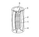
図1は、本発明の実施例1に係る骨伝導スピーカの基本構成を一部透視して示した外観斜視図である。 FIG. 1 is an external perspective view partially showing a basic configuration of a bone conduction speaker according to a first embodiment of the present invention.
この骨伝導スピーカは、音響振動発生用圧電素子としての積層型圧電アクチュエータ(積層型圧電素子)1をその長さ方向の変位を拡大するための籠状の変位拡大機構(弾性を有する外郭棒部2及び根部3から成る)を介して円筒形の容器であるゴムチューブ4の貫通穴5内に実装して成ると共に、実装状態で骨伝導音以外の気導音についても聴取可能であるように積層型圧電アクチュエータ1と貫通穴5との間に隙間を持たせた構造として外耳道に挿入して使用する形態となっている。 This bone conduction speaker is a saddle-like displacement enlarging mechanism (an elastic outer rod portion for enlarging the displacement in the length direction of a laminated piezoelectric actuator (laminated piezoelectric element) 1 as a piezoelectric element for generating acoustic vibrations. 2 and the root portion 3), and is mounted in the through
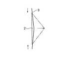
図2は、この骨伝導スピーカに備えられる変位拡大機構の動作原理を示した模式図である。図2では、主に変位拡大機構の外郭弾性棒部2における矢印で示される縦方向の変位が別の矢印で示されるほぼ中央部分での横方向の座屈変形となって直交する方向に拡大される様子を示している。係る構造では積層型圧電アクチュエータ1の長手方向の伸縮を10倍に拡大できるようになっている。 FIG. 2 is a schematic diagram showing the operation principle of the displacement enlarging mechanism provided in this bone conduction speaker. In FIG. 2, the longitudinal displacement indicated by the arrow in the outer
以下は、この骨伝導スピーカを製造する場合の工程を具体的に説明する。尚、ここで音響振動発生用圧電素子として用いる積層型圧電アクチュエータ1は、NECトーキン製の仕様名:AE0203D16と呼ばれる外形寸法が縦(長さ)20mm×横4.5mm×厚さ3.5mmのものである。 Below, the process in the case of manufacturing this bone conduction speaker is demonstrated concretely. Here, the laminated piezoelectric actuator 1 used as the acoustic vibration generating piezoelectric element has an external dimension called a specification name: AE0203D16 made by NEC TOKIN. The outer dimensions are 20 mm (length) x 4.5 mm (width) x 3.5 mm (thickness). Is.
この積層型圧電アクチュエータ1は、NECトーキン製の仕様名:N10と呼ばれる圧電セラミックス材を用いて構成されており、具体的にはそのグリーンシート(圧電セラミックスの粉末に有機バインダを混入して成膜されたシート)に銀−パラジュームの内部電極を印刷したものを約150層重ねて加圧成形した後、上述した一定のサイズに切断したものに含有される有機バインダ類を熱処理により除去してから大気中で1000℃近辺の温度条件下で焼成し、一層おきに絶縁処理層を形成すると共に、側面の引き出し電極を形成し、更に一層毎に電圧を印加できる構造にした上、リード線を半田付けした後に表面に対して耐湿防止や機械的な強度を得るために絶縁物による被覆塗装を行って作製されたものである。因みに、この積層型圧電アクチュエータ1に係る仕様(積層型圧電素子の仕様)は、直流電圧100Vで約12μの変位が得られるものである。 This multilayer piezoelectric actuator 1 is configured using a piezoelectric ceramic material called NEC TOKIN specification name: N10, and specifically, a green sheet (a film formed by mixing an organic binder into a piezoelectric ceramic powder). The sheet was printed with a silver-palladium internal electrode and approximately 150 layers were pressed and molded, and then the organic binders contained in the above-mentioned cut pieces were removed by heat treatment. Sintered in air at a temperature of around 1000 ° C. to form an insulation treatment layer every other layer, and to form a lead-out electrode on the side surface. In order to obtain moisture resistance and mechanical strength on the surface after applying, it is produced by coating with an insulating material. Incidentally, the specification (specification of the multilayer piezoelectric element) relating to the multilayer piezoelectric actuator 1 is such that a displacement of about 12 μ can be obtained at a DC voltage of 100V.
次に、上述した積層型圧電アクチュエータ1を用いて、図1に示すような弾性を有する外郭棒部2及び根部3から成る籠型の変位拡大機構と組み合わせた。この変位拡大機構において、積層型圧電アクチュエータ1の長さ方向の変位は、周囲に平行な複数の弾性棒より成る外郭棒部2に対して座屈変形を起こし、各弾性棒の中央部が側面方向に膨れるように変位するが、積層型圧電アクチュエータ1の変位に対して数倍の変位になる(但し、ここでは上述した通りに積層型圧電アクチュエータ1の長手方向の伸縮を10倍に拡大できるように設計されているものとする)ために音響振動発生の出力が効果的に得られる。尚、この変位拡大機構における弾性材料には、リン青銅を用いるものとするが、一定の弾性を有する材料であれば、その他の金属材料や有機物材料を用いることも可能である。 Next, the laminated piezoelectric actuator 1 described above was used in combination with a saddle-shaped displacement enlarging mechanism including an outer
更に、籠状の変位拡大機構について、その外周部に対して外耳道に挿入したときに痛みを感じないように例えば弾性体の一例として、円筒状の容器である厚み0.5mmのゴムチューブ4を被せた。ゴムチューブ4を被せた状態での外形口径の寸法は最大9mmとなっている。 Further, for the saddle-like displacement enlarging mechanism, a
このようにして、図1に示したような骨伝導スピーカ、即ち、ゴムチューブ4の端面から見ると籠状の変位拡大機構の中心部に積層型圧電アクチュエータ1が配置されていると共に、その間には隙間があって気導音がこの部分を通過できる構造のものを作製した。 In this way, the laminated piezoelectric actuator 1 is arranged at the center of the bone-conducting speaker as shown in FIG. Has a structure that allows air conduction sound to pass through this part.
図3は、この骨伝導スピーカの使用時における駆動状態に係る要部を拡大して示した模式図である。 FIG. 3 is an enlarged schematic view showing a main part related to a driving state when the bone conduction speaker is used.
ここでは、骨伝導スピーカの使用形態として、外耳道に差し込むことによりゴムチューブ4の外壁が外耳道内壁6に当接して外耳道内壁6を押圧した状態となる上、積層型圧電アクチュエータ1を駆動して音響振動発生させるための駆動信号として、マイクロフォン回路や一般のオーディオ機器等の音声信号源8から得られる音声信号にアンプ回路7で一定の直流バイアス電圧を印加して生成されたものを用いることを示している。 Here, as a use form of the bone conduction speaker, the outer wall of the
即ち、アンプ回路7は、積層型圧電アクチュエータ1を駆動する駆動信号を生成するため、音声信号源8から得られる音声信号の昇圧とバイアス電圧の印加とを担う。具体的に言えば、音声信号には直流(DC)バイアス230Vが印加されることにより、生成される駆動信号については、音声信号の波高値からバイアス電圧を差し引いた値で分極と逆方向に印加されて逆方向には実質上弱い電界が印加されることになるため、分極劣化の無い構成となっている。 That is, the amplifier circuit 7 is responsible for boosting the audio signal obtained from the
このような実施例1に係る骨伝導スピーカの場合、骨伝導音における音声は、音声信号6Vrms辺りから明瞭に聞き取れるようになり、20Vrms辺りで聴感として80dBの音圧レベルに匹敵するレベルに達したこと、更に、外耳道が外部に対して隙間を介して外部空間に繋がる構造であることにより、外部からの気導音の聴取には問題ないことも確認できた。 In the case of the bone conduction speaker according to the first embodiment, the sound in the bone conduction sound can be heard clearly from the sound signal around 6 Vrms, and reaches a level equivalent to the sound pressure level of 80 dB as the audibility around 20 Vrms. In addition, it was confirmed that there was no problem in listening to the air-conducted sound from the outside because the external auditory canal was connected to the outside space through a gap with respect to the outside.
本発明の骨伝導スピーカに係る技術的要旨、即ち、基本構造として、積層型圧電素子の長さ方向の変位を拡大する変位拡大機構を持たせること、並びに積層型圧電素子を駆動するための駆動信号として、音声信号源からの音声信号に一定の直流バイアス電圧を印加して生成したものを用いることを応用すれば、積層型圧電素子材料である圧電バイモルフにおける体積を増大させたり、或いは振動発生力を低減させること無しに振動発生力の周波数特性を制御可能となるため、圧電バイモルフの振動駆動源とするその他の音響システムへの適用、並びにその性能改善に極めて有用となる。 Technical gist of the bone conduction speaker of the present invention, that is, providing a displacement magnifying mechanism for enlarging the displacement in the length direction of the multilayer piezoelectric element as a basic structure, and driving for driving the multilayer piezoelectric element Applying a signal generated by applying a constant DC bias voltage to an audio signal from an audio signal source can increase the volume of a piezoelectric bimorph, a laminated piezoelectric element material, or generate vibration. Since the frequency characteristics of the vibration generating force can be controlled without reducing the force, it is extremely useful for application to other acoustic systems that use a piezoelectric bimorph as a vibration driving source and for improving the performance thereof.
1 積層型圧電アクチュエータ
2 外郭棒部
3 根部
4 ゴムチューブ
5 貫通穴
6 外耳道内壁
7 アンプ回路
8 音声信号源DESCRIPTION OF SYMBOLS 1 Laminated
Claims (4)
Translated fromJapaneseThe bone conduction speaker according to any one of claims 1 to 3, wherein a drive signal for driving the laminated piezoelectric element to generate acoustic vibration is a constant DC bias applied to an audio signal obtained from an audio signal source. A bone conduction speaker, which is generated by applying a voltage.
Priority Applications (1)
| Application Number | Priority Date | Filing Date | Title |
|---|---|---|---|
| JP2005020993AJP4558526B2 (en) | 2005-01-28 | 2005-01-28 | Bone conduction speaker |
Applications Claiming Priority (1)
| Application Number | Priority Date | Filing Date | Title |
|---|---|---|---|
| JP2005020993AJP4558526B2 (en) | 2005-01-28 | 2005-01-28 | Bone conduction speaker |
Publications (2)
| Publication Number | Publication Date |
|---|---|
| JP2006211317Atrue JP2006211317A (en) | 2006-08-10 |
| JP4558526B2 JP4558526B2 (en) | 2010-10-06 |
Family
ID=36967677
Family Applications (1)
| Application Number | Title | Priority Date | Filing Date |
|---|---|---|---|
| JP2005020993AExpired - LifetimeJP4558526B2 (en) | 2005-01-28 | 2005-01-28 | Bone conduction speaker |
Country Status (1)
| Country | Link |
|---|---|
| JP (1) | JP4558526B2 (en) |
Cited By (17)
| Publication number | Priority date | Publication date | Assignee | Title |
|---|---|---|---|---|
| JP2011523566A (en)* | 2008-05-02 | 2011-08-18 | ダイメディックス コーポレイション | Agitator for stimulating the central nervous system |
| WO2012114917A1 (en)* | 2011-02-25 | 2012-08-30 | ローム株式会社 | Talk system and finger ring for talk system |
| US8834346B2 (en) | 2008-08-22 | 2014-09-16 | Dymedix Corporation | Stimulus sequencer for a closed loop neuromodulator |
| US9313306B2 (en) | 2010-12-27 | 2016-04-12 | Rohm Co., Ltd. | Mobile telephone cartilage conduction unit for making contact with the ear cartilage |
| CN105681949A (en)* | 2016-01-15 | 2016-06-15 | 温州智宇翱华商务服务有限公司 | Bone conduction earphone |
| US9392097B2 (en) | 2010-12-27 | 2016-07-12 | Rohm Co., Ltd. | Incoming/outgoing-talk unit and incoming-talk unit |
| US9479624B2 (en) | 2012-01-20 | 2016-10-25 | Rohm Co., Ltd. | Mobile telephone |
| US9705548B2 (en) | 2013-10-24 | 2017-07-11 | Rohm Co., Ltd. | Wristband-type handset and wristband-type alerting device |
| US9729971B2 (en) | 2012-06-29 | 2017-08-08 | Rohm Co., Ltd. | Stereo earphone |
| US9742887B2 (en) | 2013-08-23 | 2017-08-22 | Rohm Co., Ltd. | Mobile telephone |
| US10013862B2 (en) | 2014-08-20 | 2018-07-03 | Rohm Co., Ltd. | Watching system, watching detection device, and watching notification device |
| US10356231B2 (en) | 2014-12-18 | 2019-07-16 | Finewell Co., Ltd. | Cartilage conduction hearing device using an electromagnetic vibration unit, and electromagnetic vibration unit |
| US10778824B2 (en) | 2016-01-19 | 2020-09-15 | Finewell Co., Ltd. | Pen-type handset |
| US10795321B2 (en) | 2015-09-16 | 2020-10-06 | Finewell Co., Ltd. | Wrist watch with hearing function |
| US10967521B2 (en) | 2015-07-15 | 2021-04-06 | Finewell Co., Ltd. | Robot and robot system |
| CN113709643A (en)* | 2021-08-27 | 2021-11-26 | 歌尔微电子股份有限公司 | Vibration pickup unit, bone voiceprint sensor and electronic equipment |
| US11526033B2 (en) | 2018-09-28 | 2022-12-13 | Finewell Co., Ltd. | Hearing device |
Citations (2)
| Publication number | Priority date | Publication date | Assignee | Title |
|---|---|---|---|---|
| JPS6331300A (en)* | 1986-07-24 | 1988-02-09 | Nec Corp | Low frequency underwater ultrasonic wave transmitter |
| JP2000166959A (en)* | 1998-12-04 | 2000-06-20 | Temuko Japan:Kk | Bone conductive speaker |
- 2005
- 2005-01-28JPJP2005020993Apatent/JP4558526B2/ennot_activeExpired - Lifetime
Patent Citations (2)
| Publication number | Priority date | Publication date | Assignee | Title |
|---|---|---|---|---|
| JPS6331300A (en)* | 1986-07-24 | 1988-02-09 | Nec Corp | Low frequency underwater ultrasonic wave transmitter |
| JP2000166959A (en)* | 1998-12-04 | 2000-06-20 | Temuko Japan:Kk | Bone conductive speaker |
Cited By (36)
| Publication number | Priority date | Publication date | Assignee | Title |
|---|---|---|---|---|
| JP2011523566A (en)* | 2008-05-02 | 2011-08-18 | ダイメディックス コーポレイション | Agitator for stimulating the central nervous system |
| US8834346B2 (en) | 2008-08-22 | 2014-09-16 | Dymedix Corporation | Stimulus sequencer for a closed loop neuromodulator |
| US8834347B2 (en) | 2008-08-22 | 2014-09-16 | Dymedix Corporation | Anti-habituating sleep therapy for a closed loop neuromodulator |
| US9894430B2 (en) | 2010-12-27 | 2018-02-13 | Rohm Co., Ltd. | Incoming/outgoing-talk unit and incoming-talk unit |
| US9313306B2 (en) | 2010-12-27 | 2016-04-12 | Rohm Co., Ltd. | Mobile telephone cartilage conduction unit for making contact with the ear cartilage |
| US10779075B2 (en) | 2010-12-27 | 2020-09-15 | Finewell Co., Ltd. | Incoming/outgoing-talk unit and incoming-talk unit |
| US9392097B2 (en) | 2010-12-27 | 2016-07-12 | Rohm Co., Ltd. | Incoming/outgoing-talk unit and incoming-talk unit |
| US9716782B2 (en) | 2010-12-27 | 2017-07-25 | Rohm Co., Ltd. | Mobile telephone |
| WO2012114917A1 (en)* | 2011-02-25 | 2012-08-30 | ローム株式会社 | Talk system and finger ring for talk system |
| US9020170B2 (en) | 2011-02-25 | 2015-04-28 | Rohm Co., Ltd. | Hearing system and finger ring for the hearing system |
| US9485559B2 (en) | 2011-02-25 | 2016-11-01 | Rohm Co., Ltd. | Hearing system and finger ring for the hearing system |
| US9980024B2 (en) | 2011-02-25 | 2018-05-22 | Rohm Co., Ltd. | Hearing system and finger ring for the hearing system |
| US10079925B2 (en) | 2012-01-20 | 2018-09-18 | Rohm Co., Ltd. | Mobile telephone |
| US9479624B2 (en) | 2012-01-20 | 2016-10-25 | Rohm Co., Ltd. | Mobile telephone |
| US10158947B2 (en) | 2012-01-20 | 2018-12-18 | Rohm Co., Ltd. | Mobile telephone utilizing cartilage conduction |
| US10778823B2 (en) | 2012-01-20 | 2020-09-15 | Finewell Co., Ltd. | Mobile telephone and cartilage-conduction vibration source device |
| US10506343B2 (en) | 2012-06-29 | 2019-12-10 | Finewell Co., Ltd. | Earphone having vibration conductor which conducts vibration, and stereo earphone including the same |
| US9729971B2 (en) | 2012-06-29 | 2017-08-08 | Rohm Co., Ltd. | Stereo earphone |
| US10834506B2 (en) | 2012-06-29 | 2020-11-10 | Finewell Co., Ltd. | Stereo earphone |
| US10075574B2 (en) | 2013-08-23 | 2018-09-11 | Rohm Co., Ltd. | Mobile telephone |
| US10237382B2 (en) | 2013-08-23 | 2019-03-19 | Finewell Co., Ltd. | Mobile telephone |
| US9742887B2 (en) | 2013-08-23 | 2017-08-22 | Rohm Co., Ltd. | Mobile telephone |
| US9705548B2 (en) | 2013-10-24 | 2017-07-11 | Rohm Co., Ltd. | Wristband-type handset and wristband-type alerting device |
| US10103766B2 (en) | 2013-10-24 | 2018-10-16 | Rohm Co., Ltd. | Wristband-type handset and wristband-type alerting device |
| US10380864B2 (en) | 2014-08-20 | 2019-08-13 | Finewell Co., Ltd. | Watching system, watching detection device, and watching notification device |
| US10013862B2 (en) | 2014-08-20 | 2018-07-03 | Rohm Co., Ltd. | Watching system, watching detection device, and watching notification device |
| US10356231B2 (en) | 2014-12-18 | 2019-07-16 | Finewell Co., Ltd. | Cartilage conduction hearing device using an electromagnetic vibration unit, and electromagnetic vibration unit |
| US10848607B2 (en) | 2014-12-18 | 2020-11-24 | Finewell Co., Ltd. | Cycling hearing device and bicycle system |
| US11601538B2 (en) | 2014-12-18 | 2023-03-07 | Finewell Co., Ltd. | Headset having right- and left-ear sound output units with through-holes formed therein |
| US10967521B2 (en) | 2015-07-15 | 2021-04-06 | Finewell Co., Ltd. | Robot and robot system |
| US10795321B2 (en) | 2015-09-16 | 2020-10-06 | Finewell Co., Ltd. | Wrist watch with hearing function |
| CN105681949A (en)* | 2016-01-15 | 2016-06-15 | 温州智宇翱华商务服务有限公司 | Bone conduction earphone |
| US10778824B2 (en) | 2016-01-19 | 2020-09-15 | Finewell Co., Ltd. | Pen-type handset |
| US11526033B2 (en) | 2018-09-28 | 2022-12-13 | Finewell Co., Ltd. | Hearing device |
| CN113709643A (en)* | 2021-08-27 | 2021-11-26 | 歌尔微电子股份有限公司 | Vibration pickup unit, bone voiceprint sensor and electronic equipment |
| CN113709643B (en)* | 2021-08-27 | 2024-04-26 | 歌尔微电子股份有限公司 | Vibration pickup unit, bone voiceprint sensor and electronic equipment |
Also Published As
| Publication number | Publication date |
|---|---|
| JP4558526B2 (en) | 2010-10-06 |
Similar Documents
| Publication | Publication Date | Title |
|---|---|---|
| JP4558526B2 (en) | Bone conduction speaker | |
| JP4761459B2 (en) | Piezoelectric vibration unit and piezoelectric speaker | |
| JP4683635B2 (en) | Receiver | |
| KR100719195B1 (en) | Acoustic vibration generating element | |
| JP4662072B2 (en) | Piezoelectric acoustic element, acoustic device, and portable terminal device | |
| JP5741580B2 (en) | Oscillator | |
| JP2007251358A (en) | Bone conduction speaker | |
| JP2005354297A (en) | Electrodynamic exciter and speaker device | |
| JP4102904B2 (en) | Acoustic transducer | |
| JP2006238072A (en) | Acoustic vibration generating piezoelectric bimorph element | |
| JP5652813B2 (en) | Electroacoustic transducer and electronic device using the same | |
| KR20140028848A (en) | Terminal and method for operating piezo speaker | |
| JP2006229647A (en) | Acoustic vibrator for bone conduction | |
| JP2006005625A (en) | Acoustic vibration generating device | |
| TW201642671A (en) | Speaker | |
| JP2006066972A (en) | Speaker device | |
| JP2015109589A (en) | Earphone | |
| JP2882346B2 (en) | Piezoelectric earphone | |
| JP5676016B2 (en) | Vibration device, sound generator, speaker system, electronic equipment | |
| JP2001016691A (en) | Piezoelectric sounding body and its production | |
| JP4989390B2 (en) | Dynamic microphone | |
| JP2011082931A (en) | Speaker | |
| JP4515348B2 (en) | Piezoelectric device for generating acoustic signals | |
| JP5927944B2 (en) | Piezoelectric sounding device | |
| CN1729715B (en) | Acoustic actuators |
Legal Events
| Date | Code | Title | Description |
|---|---|---|---|
| A621 | Written request for application examination | Free format text:JAPANESE INTERMEDIATE CODE: A621 Effective date:20080110 | |
| A977 | Report on retrieval | Free format text:JAPANESE INTERMEDIATE CODE: A971007 Effective date:20100309 | |
| A131 | Notification of reasons for refusal | Free format text:JAPANESE INTERMEDIATE CODE: A131 Effective date:20100407 | |
| A521 | Request for written amendment filed | Free format text:JAPANESE INTERMEDIATE CODE: A523 Effective date:20100602 | |
| TRDD | Decision of grant or rejection written | ||
| A01 | Written decision to grant a patent or to grant a registration (utility model) | Free format text:JAPANESE INTERMEDIATE CODE: A01 Effective date:20100630 | |
| A01 | Written decision to grant a patent or to grant a registration (utility model) | Free format text:JAPANESE INTERMEDIATE CODE: A01 | |
| A61 | First payment of annual fees (during grant procedure) | Free format text:JAPANESE INTERMEDIATE CODE: A61 Effective date:20100721 | |
| R150 | Certificate of patent or registration of utility model | Ref document number:4558526 Country of ref document:JP Free format text:JAPANESE INTERMEDIATE CODE: R150 Free format text:JAPANESE INTERMEDIATE CODE: R150 | |
| FPAY | Renewal fee payment (event date is renewal date of database) | Free format text:PAYMENT UNTIL: 20130730 Year of fee payment:3 | |
| FPAY | Renewal fee payment (event date is renewal date of database) | Free format text:PAYMENT UNTIL: 20140730 Year of fee payment:4 | |
| R250 | Receipt of annual fees | Free format text:JAPANESE INTERMEDIATE CODE: R250 | |
| R250 | Receipt of annual fees | Free format text:JAPANESE INTERMEDIATE CODE: R250 | |
| R250 | Receipt of annual fees | Free format text:JAPANESE INTERMEDIATE CODE: R250 | |
| R250 | Receipt of annual fees | Free format text:JAPANESE INTERMEDIATE CODE: R250 | |
| S533 | Written request for registration of change of name | Free format text:JAPANESE INTERMEDIATE CODE: R313533 | |
| R350 | Written notification of registration of transfer | Free format text:JAPANESE INTERMEDIATE CODE: R350 | |
| R250 | Receipt of annual fees | Free format text:JAPANESE INTERMEDIATE CODE: R250 | |
| R250 | Receipt of annual fees | Free format text:JAPANESE INTERMEDIATE CODE: R250 | |
| R250 | Receipt of annual fees | Free format text:JAPANESE INTERMEDIATE CODE: R250 | |
| R250 | Receipt of annual fees | Free format text:JAPANESE INTERMEDIATE CODE: R250 | |
| R250 | Receipt of annual fees | Free format text:JAPANESE INTERMEDIATE CODE: R250 | |
| R250 | Receipt of annual fees | Free format text:JAPANESE INTERMEDIATE CODE: R250 | |
| R250 | Receipt of annual fees | Free format text:JAPANESE INTERMEDIATE CODE: R250 | |
| EXPY | Cancellation because of completion of term |