JP2006209948A - Optical disk drive - Google Patents
Optical disk driveDownload PDFInfo
- Publication number
- JP2006209948A JP2006209948AJP2006015153AJP2006015153AJP2006209948AJP 2006209948 AJP2006209948 AJP 2006209948AJP 2006015153 AJP2006015153 AJP 2006015153AJP 2006015153 AJP2006015153 AJP 2006015153AJP 2006209948 AJP2006209948 AJP 2006209948A
- Authority
- JP
- Japan
- Prior art keywords
- case
- main case
- optical
- disk drive
- optical disk
- Prior art date
- Legal status (The legal status is an assumption and is not a legal conclusion. Google has not performed a legal analysis and makes no representation as to the accuracy of the status listed.)
- Withdrawn
Links
- 230000003287optical effectEffects0.000titleclaimsabstractdescription183
- 241001465754MetazoaSpecies0.000claimsdescription13
- 241000283690Bos taurusSpecies0.000claimsdescription3
- 230000004048modificationEffects0.000description51
- 238000012986modificationMethods0.000description51
- 238000000034methodMethods0.000description17
- 230000008878couplingEffects0.000description3
- 238000010168coupling processMethods0.000description3
- 238000005859coupling reactionMethods0.000description3
Images


Classifications
- G—PHYSICS
- G11—INFORMATION STORAGE
- G11B—INFORMATION STORAGE BASED ON RELATIVE MOVEMENT BETWEEN RECORD CARRIER AND TRANSDUCER
- G11B33/00—Constructional parts, details or accessories not provided for in the other groups of this subclass
- G11B33/02—Cabinets; Cases; Stands; Disposition of apparatus therein or thereon
- G—PHYSICS
- G11—INFORMATION STORAGE
- G11B—INFORMATION STORAGE BASED ON RELATIVE MOVEMENT BETWEEN RECORD CARRIER AND TRANSDUCER
- G11B33/00—Constructional parts, details or accessories not provided for in the other groups of this subclass
- G11B33/12—Disposition of constructional parts in the apparatus, e.g. of power supply, of modules
- G11B33/121—Disposition of constructional parts in the apparatus, e.g. of power supply, of modules the apparatus comprising a single recording/reproducing device
Landscapes
- Feeding And Guiding Record Carriers (AREA)
- Supporting Of Heads In Record-Carrier Devices (AREA)
- Automatic Disk Changers (AREA)
Abstract
Description
Translated fromJapanese本発明はデータ読み取り機器に関し、特に光ディスクドライブに関するものである。 The present invention relates to a data reading device, and more particularly to an optical disk drive.
コンパクトディスクは、従来の磁気記憶媒体に徐々に取って代わり、現代生活に不可欠な情報記憶媒体のうちの1つになった。コンパクトディスクは、記憶容量がより大きく、保管も容易であり、より長い記憶寿命を有し、コストもより低くて、容易にデータの損害を受けにくいなどの利点がある。コンパクトディスクは上記の全ての利点があるにもかかわらず、パーソナルコンピュータ(パソコン)が小型化の傾向をたどり、より薄くより軽くなってくるにつれて、光ディスクドライブはその巨大なハウジングのゆえに、パソコンおよびノートパソコンの薄型化、小型化を妨げる理由の一つとなった。 Compact disks have gradually replaced conventional magnetic storage media and have become one of the information storage media indispensable for modern life. The compact disk has advantages such as a larger storage capacity, easier storage, a longer storage life, a lower cost, and is less easily damaged by data. Despite all of the advantages described above, compact discs have become smaller and lighter as personal computers (personal computers) have become smaller and lighter. This was one of the reasons that hindered the thinning and miniaturization of personal computers.
一般に、デスクトップコンピュータに使用される光ディスクドライブは主に光ピックアップモジュールとハウジングとから成り、その光ピックアップモジュールは係合要素、光ピックアップおよびトレイを有する。係合要素と光ピックアップはハウジング内に配置されている。その一方で、トレイはハウジングに接続された滑動物である。コンパクトディスクがトレイに入れられたあと、トレイはハウジングに対する相対運動によってハウジングにコンパクトディスクを運ぶ。次に、コンパクトディスクは係合要素によって固定され、回転させられる。そして、コンパクトディスクに書き込まれたデータは光ピックアップによって読み込まれる。しかしながら、デスクトップコンピュータで使用される光ディスクドライブは、その過剰な大きさにより、ノートパソコンの、薄さ、重量並びに大きさに対する要求を満たすことができない。 In general, an optical disk drive used in a desktop computer mainly includes an optical pickup module and a housing, and the optical pickup module includes an engaging element, an optical pickup, and a tray. The engaging element and the optical pickup are disposed in the housing. On the other hand, the tray is a cattle animal connected to the housing. After the compact disc is placed in the tray, the tray carries the compact disc to the housing by relative movement with respect to the housing. The compact disc is then fixed by the engaging element and rotated. The data written on the compact disc is read by the optical pickup. However, the optical disk drive used in the desktop computer cannot satisfy the demands on the thinness, weight and size of the notebook personal computer due to its excessive size.
それゆえ、従来の光ディスクドライブは、ノートパソコンでの使用に適切な大きさを有する他の構造設計を提唱している。この種の構造設計において、係合要素と、光ピックアップとトレイとは、光モジュール内で直接組み合わされている。更に、相対的な滑動が、光モジュールとハウジングとの間で行われる。それゆえ、コンパクトディスクが光モジュールに挿入されると、光モジュールはハウジングに対する相対的な滑動を経てハウジングにコンパクトディスクを運ぶことができ、コンパクトディスクのデータを読み込む。上記の方法は、ノートパソコンにおいて使用される光ディスクドライブをデスクトップコンピュータのものより小さくするために、光ディスクドライブの体積を減少させることはできるが、ノートパソコンにおいて使用される光ディスクドライブの体積は未だにノートパソコンの全体積の大きな部分を占めている。 Therefore, the conventional optical disk drive has proposed another structural design having an appropriate size for use in a notebook computer. In this type of structural design, the engagement element, the optical pickup and the tray are directly combined in the optical module. Furthermore, relative sliding is performed between the optical module and the housing. Therefore, when the compact disk is inserted into the optical module, the optical module can carry the compact disk to the housing through relative sliding with respect to the housing and read the data of the compact disk. Although the above method can reduce the volume of the optical disk drive in order to make the optical disk drive used in the notebook computer smaller than that of the desktop computer, the volume of the optical disk drive used in the notebook computer is still the notebook computer. Occupy a large part of the total volume.
したがって、本発明は、体積を可動ハウジング機構によって小型化する光ディスクドライブを提供することを目的とする。 Accordingly, an object of the present invention is to provide an optical disc drive whose volume is reduced by a movable housing mechanism.
本発明は、コンパクトディスクのデータの読み込みに適した光ディスクドライブを提供する。前記光ディスクドライブは、光ピックアップモジュールとハウジングとを有する。光ピックアップモジュールは、更に係合要素としてのダンパと、光ピックアップとを有する。ダンパはコンパクトディスクを固定するために用いられ、光ピックアップはそのダンパの近くに配置されて、コンパクトディスクのデータを読み込むために用いられる。ハウジングは、主ケースおよび可動ケースを含んでおり、光ピックアップモジュールに接続されている。主ケースは光ピックアップモジュールに接続され、コンパクトディスクの一部を保持するのに適している。可動ケースは、主ケースに組み合わされており、その可動ケースと主ケースとの両方によってコンパクトディスクを収容するために主ケースに対する相対運動をもたらすのに適している。 The present invention provides an optical disc drive suitable for reading data from a compact disc. The optical disc drive includes an optical pickup module and a housing. The optical pickup module further includes a damper as an engagement element and an optical pickup. The damper is used to fix the compact disc, and the optical pickup is arranged near the damper and used to read the data on the compact disc. The housing includes a main case and a movable case, and is connected to the optical pickup module. The main case is connected to the optical pickup module and is suitable for holding a part of the compact disc. The movable case is combined with the main case and is suitable for providing relative movement with respect to the main case to accommodate the compact disc by both the movable case and the main case.
本発明の実施形態記載の光ディスクドライブによれば、上記光ピックアップモジュールは、例えばコンパクトディスクを保持するためのトレイを有する。 According to the optical disk drive described in the embodiment of the present invention, the optical pickup module has a tray for holding, for example, a compact disk.
本発明の実施形態記載の光ディスクドライブによれば、上記可動ケースは、例えば組み立て式構体である。 According to the optical disk drive described in the embodiment of the present invention, the movable case is, for example, an assembly type structure.
本発明の実施形態記載の光ディスクドライブによれば、上記可動ケースは、例えば折り畳み式機構を有し、その折り畳み式機構は例えば複数の折り畳み板であっても良い。 According to the optical disk drive described in the embodiment of the present invention, the movable case has, for example, a folding mechanism, and the folding mechanism may be, for example, a plurality of folding plates.
本発明の実施形態記載の光ディスクドライブによれば、上記折り畳み板は、例えば複数の保持板および複数のカバー板を有する。それら保持板およびカバー板は、主ケースと保持板との間に、板間の相対運動によって、コンパクトディスクを保持するのに十分大きい保持平面を形成するのに適しており、カバー板はその保持平面を覆うのに適している。 According to the optical disk drive described in the embodiment of the present invention, the folding plate has, for example, a plurality of holding plates and a plurality of cover plates. The holding plate and the cover plate are suitable for forming a holding plane large enough to hold the compact disc between the main case and the holding plate by the relative movement between the plates. Suitable for covering flat surfaces.
本発明の実施形態記載の光ディスクドライブによれば、上記主ケースは、例えば、第1の開口空間を有し、可動ケースおよび主ケースは、例えば、互いに対して相対運動をすることにより第2の開口空間を形成することができ、第1および第2の開口空間は一緒にコンパクトディスクを相互に収容するのに適している。 According to the optical disk drive described in the embodiment of the present invention, the main case has, for example, a first opening space, and the movable case and the main case have, for example, a second motion by making relative movement with respect to each other. An open space can be formed, the first and second open spaces being suitable for accommodating the compact disc together.
本発明の実施形態記載の光ディスクドライブによれば、上記可動ケースは、例えば、可動要素を有し、それは主ケースの表面に回転可能なように支持されている。 According to the optical disk drive of the embodiment of the present invention, the movable case has, for example, a movable element, and is supported on the surface of the main case so as to be rotatable.
本発明の実施形態記載の光ディスクドライブによれば、上記可動ケースは、例えば、主ケース内に配置された滑動物を有する。 According to the optical disk drive described in the embodiment of the present invention, the movable case has, for example, a sliding animal disposed in the main case.
本発明の実施形態記載の光ディスクドライブによれば、上記可動ケースは、例えば、可動要素と滑動物とを組み合わせたものであっても良い。 According to the optical disk drive described in the embodiment of the present invention, the movable case may be, for example, a combination of a movable element and a slide animal.
本発明の実施形態記載の光ディスクドライブによれば、上記可動ケースは、例えば、環状の摺動カバーを有し、その摺動カバーは、例えば更に複数の相互接続された扇形の摺動カバーを有する。 According to the optical disk drive of the embodiment of the present invention, the movable case has, for example, an annular sliding cover, and the sliding cover further has, for example, a plurality of interconnected fan-shaped sliding covers. .
本発明の実施形態記載の光ディスクドライブによれば、可動ケースは、例えば、主ケース内に配置された複数の帯状ケースを有し、それらの帯状ケースの両端は主ケースから同時に滑動または回転して出るのに適している。 According to the optical disc drive described in the embodiment of the present invention, the movable case has, for example, a plurality of belt-like cases arranged in the main case, and both ends of the belt-like cases slide or rotate simultaneously from the main case. Suitable for getting out.
本発明においては、ハウジングが主ケースおよび可動ケースを有するよう設計されているので、光ディスクドライブの体積が減少する。光ディスクドライブがコンパクトディスクに書き込まれたデータを読み込む必要がある時、可動ケースは主ケースから外側に引き出すことができ、コンパクトディスクは主ケースと可動ケースとの両方によって相互に収容される。 In the present invention, the volume of the optical disc drive is reduced because the housing is designed to have a main case and a movable case. When the optical disc drive needs to read data written on the compact disc, the movable case can be pulled out from the main case, and the compact disc is accommodated by both the main case and the movable case.
本発明の前記目的や他の目的、特徴および利点をより明らかにするために、図を伴った実施形態を以下に詳細に記載する。前述の概要と以下の詳細な説明とは例示であり、請求の範囲記載の本発明の更なる説明をもたらすことを意図したものであることを理解するべきである。 In order to make the aforementioned and other objects, features, and advantages of the present invention more apparent, embodiments with drawings are described in detail below. It should be understood that the foregoing summary and the following detailed description are exemplary and are intended to provide further explanation of the invention as claimed.
以下、本発明の実施形態を実施例により、添付図面に基づき詳細に説明する。 Embodiments of the present invention will be described below in detail with reference to the accompanying drawings.
これらの図面は本発明の実施例を示しており、発明の詳細な説明と共に本発明の原理を解説するためのものである。 These drawings illustrate embodiments of the invention and together with the detailed description, serve to explain the principles of the invention.
本発明は光ディスクドライブを提供する。本発明の主な目的は、光ディスクドライブの体積を減少させるために、光ディスクドライブのハウジングを2つの部品、すなわち主ケースおよび可動ケースに分割することである。光ディスクドライブがコンパクトディスクに書き込まれたデータを読み込む必要がある時、可動ケースは主ケースから外側に拡張することができ、コンパクトディスクは主ケースおよび可動ケース両方の内側に収容される。そして、主ケースに配置された光ピックアップモジュールによりデータが読み込まれる。関連した実施の方法は、以下の実施例によって理解されるであろう。 The present invention provides an optical disc drive. The main object of the present invention is to divide the housing of the optical disk drive into two parts, a main case and a movable case, in order to reduce the volume of the optical disk drive. When the optical disc drive needs to read data written on the compact disc, the movable case can be extended outward from the main case, and the compact disc is accommodated inside both the main case and the movable case. Data is read by the optical pickup module arranged in the main case. The manner of related implementation will be understood by the following examples.
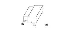
図1は、本発明の第1実施例の光ディスクドライブの斜視図である。図2は、本発明の第1実施例による、I〜I’方向に沿う主ケースの断面図である。図1と図2とを参照すると、光ディスクドライブ100はハウジング110および光ピックアップモジュール120を有している。ハウジング110は主ケース112および可動ケース114を有している。そして、光ピックアップモジュール120はダンパ122および光ピックアップ124を有している。光ピックアップモジュール120は主ケース112内に配置されており、ここでダンパ122はコンパクトディスクと係合するために用いられ、光ピックアップ124はコンパクトディスクに書き込まれたデータを読み込むために用いられる。この主ケース112の外側設計は単独でコンパクトディスクを収容することを不可能にする。更に、光ピックアップモジュール120は、例えば、コンパクトディスクを保持するために、更にトレイ(図示せず)を有していても良い。 FIG. 1 is a perspective view of an optical disk drive according to a first embodiment of the present invention. FIG. 2 is a cross-sectional view of the main case along the directions I to I ′ according to the first embodiment of the present invention. Referring to FIGS. 1 and 2, the
図3〜5は、本発明の第1実施例の光ディスクドライブのハウジングの変形を例示した複数の斜視図である。図1および図3〜5を共に参照すると、第1実施例において、光ディスクドライブ100の可動ケース114は組み立て式構体形式のものである。可動ケース114は主ケース112の一部を収容するための空間を有している。光ディスクドライブ100がコンパクトディスク130に書き込まれたデータを読み込む必要がない時、光ディスクドライブ100は、可動ケース114の表面Bおよび主ケース112の表面Cを同一の方向に向けることができ、そして、光ディスクドライブの体積を減少させるために主ケース112を可動ケース114内に収容することができる(図3参照)。光ディスクドライブによりコンパクトディスク130に書き込まれたデータを読み込むことを意図する時には、最初に例えばコンパクトディスク130を矢印140の方向に沿って主ケース112に挿入する。次に主ケース112を可動ケース114から分離して、可動ケース114の表面Bと主ケース112の表面Cとを互い向きあわせて配置する。そして、コンパクトディスク130を主ケース112と可動ケース114との両方によって収容さるために、矢印150の方向に沿って可動ケース114に主ケース112を覆わせる(図4、5参照)。 3 to 5 are a plurality of perspective views illustrating modifications of the housing of the optical disk drive according to the first embodiment of the present invention. Referring to FIGS. 1 and 3 to 5 together, in the first embodiment, the
図6は、本発明の他の実施例の光ディスクドライブのハウジングの変形を例示した斜視図である。図3および図6を参照すると、可動ケース114と主ケース112との間の相対運動は、前記実施例に示した方法に加えて、例えば、相対的な滑動でも良い。すなわち、光ディスクドライブ100によりコンパクトディスク130のデータを読み込むことを意図する時、主ケース112は、例えば、矢印160の方向に沿って摺動させて可動ケース114から出すことも可能である。そして、可動ケース114および主ケース112の内側に、コンパクトディスクを収容できる十分な大きさの空間を形成する。次に、コンパクトディスク130が、そのコンパクトディスク130に書き込まれたデータを読み込むために光ディスクドライブ100に挿入される。 FIG. 6 is a perspective view illustrating a modification of a housing of an optical disk drive according to another embodiment of the present invention. Referring to FIGS. 3 and 6, the relative movement between the
上記説明に基づけば、前記実施例の主な意図は、主ケースを可動ケースに相対運動可能に結合し、光ディスクドライブを小型化することにある。光ディスクドライブがコンパクトディスクに書き込まれたデータを読み込む必要がある時、光ディスクドライブは、可動ケースと主ケースとの間の相対運動によって、可動ケースと主ケースとの両方にコンパクトディスクを収容させることができる。可動ケースと主ケースとの間の相対運動は上記2つの方法に限られない。その代わり、コンパクトディスクを可動ケースおよび主ケースに相互に収容させ得る限り、あらゆる運動方法が上記実施例に保護される範囲に含まれる。 Based on the above description, the main intent of the above embodiment is to connect the main case to the movable case so as to allow relative movement, and to reduce the size of the optical disk drive. When the optical disk drive needs to read data written on the compact disk, the optical disk drive can accommodate the compact disk in both the movable case and the main case by the relative movement between the movable case and the main case. it can. The relative motion between the movable case and the main case is not limited to the above two methods. Instead, as long as the compact disk can be accommodated in the movable case and the main case, all the movement methods are included in the scope protected by the above embodiment.
光ディスクドライブの上記構成に基づく、可動ケースの構造および動き方を以下に例示する。 The structure and movement method of the movable case based on the above configuration of the optical disk drive will be exemplified below.
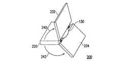
図7〜9は、本発明の第2実施例の光ディスクドライブのハウジングの変形を例示した複数の斜視図である。図7〜9を参照すると、光ディスクドライブ200のハウジング210は主ケース220および可動ケース230を有している。主ケース220はコンパクトディスク130の一部を保持するための空間212を有し、可動ケース230は可動要素232および234を有している。可動要素232および234は、軸結合部236および238によって主ケース220に回転可能にそれぞれ接続されている(図7参照)。光ディスクドライブ200により、コンパクトディスク130に書き込まれたデータを読み込むことを意図する時、最初に、コンパクトディスク130の一部が空間212に挿入される。その後に、可動要素232および234は、軸結合部236および238をそれぞれ回転支持部として、主ケース220に対し矢印240および242の方向に回転させられている(図8参照)。そして空間250が、コンパクトディスク130を空間212と空間250との両方に相互に収容させるために、可動要素232および234の間に形成される。 7 to 9 are a plurality of perspective views illustrating modifications of the housing of the optical disk drive according to the second embodiment of the present invention. 7 to 9, the
上記説明に基づけば、前記実施例の主な意図は、光ディスクドライブを小型化するために、1つ以上の可動要素を、軸支要素によって主ケースに回転可能に接続することにある。光ディスクドライブがコンパクトディスクに書き込まれたデータを読み込む必要がある時、可動要素は、軸支要素と主ケースとの間の相互回転運動によって、可動要素および主ケース両方に、コンパクトディスクを相互に収容させることができる。可動要素と主ケースとの間の相対運動は前記方法に限られない。その代わり、あらゆる運動方法が、可動要素よって形成された空間および主ケースによって占められた空間の両方にコンパクトディスクを相互に収容させ得る限り、前記実施例によって定義された範囲に含まれる。 Based on the above description, the main intent of the above embodiment is to rotatably connect one or more movable elements to the main case by means of pivot elements in order to reduce the size of the optical disk drive. When the optical disk drive needs to read the data written on the compact disk, the movable element mutually accommodates the compact disk in both the movable element and the main case by the mutual rotational movement between the pivotal support element and the main case. Can be made. The relative movement between the movable element and the main case is not limited to the above method. Instead, any method of movement is included in the range defined by the previous examples, as long as the compact disc can be accommodated in both the space formed by the movable element and the space occupied by the main case.
図10〜11は、本発明の第3実施例の光ディスクドライブのハウジングの変形を例示した複数の斜視図である。図10〜11を参照すると、光ディスクドライブ300のハウジング310は主ケース320および可動ケース330を有している。主ケース320はコンパクトディスク130の一部を保持するための空間312を有している。可動ケース330は滑動物332および334を有している。滑動物332および334は主ケース320内に収容されるのに適している。光ディスクドライブ300により、コンパクトディスク130に書き込まれたデータを読み込むことを意図する時、コンパクトディスク130の一部が空間312に挿入され、そして、滑動物332および334が矢印340の方向に沿って摺動させられる。この場合の摺動方法は、例えば、滑動物332および334をバネの使用によって飛び出させることである(図10参照)。その後に、コンパクトディスク130は、滑動物332および334間に形成された空間350と空間312との両方に形成された空間に収容される。 10 to 11 are a plurality of perspective views illustrating modifications of the housing of the optical disk drive according to the third embodiment of the invention. Referring to FIGS. 10 to 11, the
上記説明に基づけば、前記実施例の主な意図は、光ディスクドライブを小型化するために、1つ以上の滑動物を主ケースに収容することにある。光ディスクドライブがコンパクトディスクに書き込まれたデータを読み込む必要がある時、この滑動物は、その滑動物と主ケースとの間の相対的な滑動によって、この滑動物と主ケースとの両方により相互にコンパクトディスクを収容することができる。滑動物と主ケースとの間の相対運動は前記方法に限られない。その代わり、あらゆる運動方法が、滑動物によって形成された空間と主ケースによって占められた空間との両方にコンパクトディスクを相互に収容させ得る限り、前記実施例によって定義された範囲に含まれる。 Based on the above description, the main intent of the embodiment is to accommodate one or more animals in the main case in order to reduce the size of the optical disk drive. When the optical disk drive needs to read the data written on the compact disc, the slides will interact with each other by both the slide and the main case due to the relative sliding between the slide and the main case. A compact disc can be accommodated. The relative movement between the cattle animal and the main case is not limited to the above method. Instead, any method of movement is included in the range defined by the previous examples, so long as the compact disc can be accommodated in both the space formed by the animal and the space occupied by the main case.
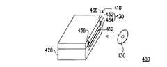
図12〜14は、本発明の第4実施例の光ディスクドライブのハウジングの変形を例示した複数の斜視図である。図12〜14を参照すると、上記実施例は第2実施例と第3実施例との組み合わせである。光ディスクドライブ400のハウジング410は主ケース420および可動ケース430を有している。主ケース420はコンパクトディスク130の一部を保持するための空間412を有し、可動ケース430は可動要素432および滑動物434を有している。可動要素432は、軸結合部436によって主ケース420に回転可能に接続されている。光ディスクドライブ400は、可動要素432と主ケース420との間の相対的な回転、および、滑動物434と主ケース420との間の相対的な滑動により可動要素432と滑動物434により形成された空間450と、主ケース420により占められた空間412との両方に、コンパクトディスク130を相互に収容させる。 12 to 14 are a plurality of perspective views illustrating the deformation of the housing of the optical disk drive according to the fourth embodiment of the invention. Referring to FIGS. 12 to 14, the above embodiment is a combination of the second embodiment and the third embodiment. The
前記実施例は、一方の側で、コンパクトディスクを主ケースと可動ケースとの両方に相互に収容させているが、前記実施例の意図に従って、両側で、コンパクトディスクを主ケースと可動ケースとの両方に相互に収容させる設計を更に提示することができるという点に留意する必要がある。 In the above embodiment, the compact disk is mutually accommodated in both the main case and the movable case on one side, but in accordance with the intention of the above embodiment, the compact disk is disposed between the main case and the movable case on both sides. It should be noted that a design can be further presented that allows both to accommodate each other.
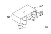
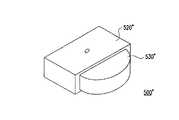
図15〜17は、本発明の第5実施例の光ディスクドライブのハウジングの変形を例示した複数の斜視図である。図15〜17を参照すると、光ディスクドライブ500のハウジング510は主ケース520および可動ケース530を有している。主ケース520はコンパクトディスク130の一部を保有するための空間512を有している。可動ケース530は複数の環状の摺動カバー532および534を有し、それらは主ケース520内に収容されている。光ディスクドライブ500により、コンパクトディスク130に書き込まれたデータを読み込むことを意図する時、最初に、コンパクトディスク130が矢印540の方向に沿って空間512に挿入され、そして、コンパクトディスク130が主ケース520を貫通する。次に、環状の摺動カバー532および534が、それら環状の摺動カバー532および524に囲まれた空間550にコンパクトディスク130を徐々に引き入れるように、矢印514および516の方向に沿ってそれぞれ摺動させられる。最後に、コンパクトディスク130が、環状の摺動カバー532と534とによって形成された空間550と主ケース520とに完全に相互に収容される。 15 to 17 are a plurality of perspective views illustrating modifications of the housing of the optical disk drive according to the fifth embodiment of the invention. 15 to 17, the
図18〜19は、本発明の第5実施例の光ディスクドライブのハウジングのもう一つの変形例を示した複数の斜視図である。図15,18および19を参照すると、光ディスクドライブ500’において、例えば、図16の環状の摺動カバーに代えて、複数の扇形の摺動カバー532’および534’を用いることができる。そして、コンパクトディスクは、扇形の摺動カバー532’および534’によって形成された空間550’中に、上記の同様の方法で収容される。 18 to 19 are a plurality of perspective views showing another modification of the housing of the optical disk drive according to the fifth embodiment of the present invention. Referring to FIGS. 15, 18 and 19, in the optical disc drive 500 ', for example, a plurality of fan-shaped sliding
図20〜22は、本発明の他の実施例の光ディスクドライブのハウジングの一つの変形を例示した複数の斜視図である。図20〜22を参照すると、光ディスクドライブ500’’のハウジング510’’は主ケース520’’および可動ケース530’’を有している。主ケース520’’はコンパクトディスク130の一部を保持するための空間512’’を有している。可動ケース530’’は環状の摺動カバー532’’および534’’を有し、それらは主ケース520’’に収容されている。光ディスクドライブ500’’によりコンパクトディスク130に書き込まれたデータを読み込むことを意図する時、コンパクトディスク130は矢印540’’の方向に沿って空間512’’に挿入され、コンパクトディスク130は主ケース520’’に収容される。ここでのコンパクトディスク130と主ケース520’’との間の相対位置は、前記実施例の相対位置とは異なっていても良く、例えば主ケース520’’を貫通しなくてもいいという点に留意する必要がある(図20参照)。次いで、環状の摺動カバー532’’および534’’が、それら環状の摺動カバー532’’および524’’によって形成された空間550’’にコンパクトディスク130を徐々に引き入れるように、矢印514’’および516’’の方向に沿ってそれぞれ摺動される。最後に、コンパクトディスク130が、環状の摺動カバー532’’と534’’とによって形成された空間550’’と主ケース520’’とに完全に相互に収容される。 20 to 22 are a plurality of perspective views illustrating one modification of the housing of the optical disk drive according to another embodiment of the present invention. Referring to FIGS. 20 to 22, the
上記説明に基づけば、前記実施例の主な意図は、光ディスクドライブの体積を減少させるために、1つ以上の環状の摺動カバーを主ケースに収容させることにある。光ディスクドライブがコンパクトディスクに書き込まれたデータを読み込む必要がある時、環状の摺動カバーは、その環状の摺動カバーと主ケースとの間の相対的な摺動により、環状の摺動カバーによって形成された空間に、コンパクトディスクが環状の摺動カバーと主ケースとによって形成された両空間に完全に相互に収容されるまでコンパクトディスクを徐々に引き入れることができる。環状の摺動カバーと主ケースとの間の相対運動は前記方法に限られない。その代わり、あらゆる運動方法は、コンパクトディスクを環状の摺動カバーと主ケースとの両方に囲ませることができる限り、本実施例によって定義された範囲に含まれる。 Based on the above description, the main intention of the embodiment is to accommodate one or more annular sliding covers in the main case in order to reduce the volume of the optical disk drive. When the optical disk drive needs to read the data written on the compact disc, the annular sliding cover is moved by the annular sliding cover due to the relative sliding between the annular sliding cover and the main case. The compact disc can be gradually pulled into the formed space until the compact disc is completely accommodated in both spaces formed by the annular sliding cover and the main case. The relative movement between the annular sliding cover and the main case is not limited to the above method. Instead, any method of movement is included in the scope defined by this embodiment as long as the compact disc can be surrounded by both the annular sliding cover and the main case.
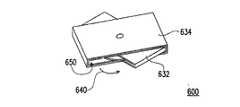
図23〜25は、本発明の第6実施例の光ディスクドライブのハウジングの変形を例示した複数の斜視図である。光ディスクドライブ600のハウジング610は、主ケース620および可動ケース630を有している。この可動ケースは複数の帯状ケース632および634を有し、それらは主ケース620の外側に受容されている。光ディスクドライブ600により、コンパクトディスク130に書き込まれたデータを読み込むことを意図する時、コンパクトディスク130が主ケース620に挿入されて貫通され、コンパクトディスクの一部は主ケース620に収容される。その後に、帯状ケース632および634の両端が主ケース620から同時に回転して外に出られるように、帯状ケース632および634が主ケース620に対して矢印640の方向に沿ってそれぞれ回転し、帯状ケース632および634によって形成された空間650に、コンパクトディスクを徐々に引き入れていく。そして最後に、コンパクトディスク130が、帯状ケース632,634によって形成された空間650と主ケース620とに完全に相互に収容される。 23 to 25 are a plurality of perspective views illustrating modifications of the housing of the optical disk drive according to the sixth embodiment of the present invention. A
上記説明に基づけば、前記実施例の主な意図は、光ディスクドライブの体積を減少させるために、1つ以上の帯状ケースを主ケースに受容させることにある。光ディスクドライブがコンパクトディスクに書き込まれたデータを読み込む必要がある時、帯状ケースは、その帯状ケースと主ケースとの間の相対回転によって、コンパクトディスクが帯状ケースと主ケースとによって形成された両空間に完全に相互に収容されるまでその帯状ケースによって形成された空間にコンパクトディスクを徐々に引き入れることができる。帯状ケースと主ケースとの間の相対運動は前記方法に限られない。その代わり、あらゆる運動方法は、コンパクトディスクを帯状ケースと主ケースとの両方により囲ませることができる限り、前記実施例によって定義された範囲に含まれる。 Based on the above description, the main intention of the above embodiment is to accept one or more belt-like cases in the main case in order to reduce the volume of the optical disk drive. When the optical disk drive needs to read the data written on the compact disk, the band-shaped case has both spaces formed by the band-shaped case and the main case by the relative rotation between the band-shaped case and the main case. The compact disc can be gradually drawn into the space formed by the belt-like case until it is completely accommodated. The relative motion between the belt-like case and the main case is not limited to the above method. Instead, any method of movement is included in the range defined by the previous examples as long as the compact disc can be surrounded by both the strip case and the main case.
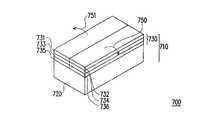
図26〜28は、本発明の第7実施例の光ディスクドライブのハウジングの変形を例示した複数の斜視図である。図26〜28を参照すると、光ディスクドライブ700のハウジング710は主ケース720および可動ケース730を有している。可動ケース730は複数の折り畳み板を有し、そこにおいて折り畳み板は、例えば、カバー板731〜734および保持板735,736を更に有している。カバー板732はカバー板734に接続され、カバー板734は保持板736に接続されている。そして保持板736は更に主ケース720に接続されており、接続方法は回転可能な接続であってもよい。カバー板731、733および保持板735も、同様の方法で相互に接続されている。 26 to 28 are a plurality of perspective views illustrating modifications of the housing of the optical disk drive according to the seventh embodiment of the invention. Referring to FIGS. 26 to 28, the
更に図26〜28を参照すると、光ディスクドライブ700がコンパクトディスク130に書き込まれたデータを読み込む必要がない時、光ディスクドライブの体積を減少させるために、カバー板731〜734および保持板735,736は、例えば図26に示すように、それらの相互接続によって、カバー板731,732の下に、カバー板733,734および保持板735,736を隠すことができる。光ディスクドライブ700によりコンパクトディスク130に書き込まれたデータを読み込むことを意図する時、カバー板731〜734および保持板735,736は、それぞれ矢印750と751の方向に沿って伸ばすことができ、この結果、保持プラットフォーム738が、コンパクトディスク130を保持するために保持板735,736と主ケース720とによって形成され、そして、コンパクトディスクを収容するのに十分大きい空間が、カバー板731〜734で保持プラットフォーム738を覆うことによって形成される。 26 to 28, the
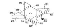
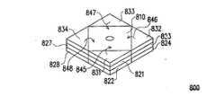
図29〜34は、本発明の第8実施例の光ディスクドライブのハウジングの変形を例示した複数の斜視図である。この第8の実施例におけるカバー板および保持板は、この第8の実施例に従って配置することができる。図29〜34を参照すると、光ディスクドライブ800は主ケース810、カバー板821〜828および保持板831〜834を有している。主ケース810および保持板831〜834は共にコンパクトディスク130を保持するように保持プラットフォーム840を形成する。光ディスクドライブ800がコンパクトディスク130のデータを読み込む必要がある時、コンパクトディスク130を保持プラットフォーム840上に配置することができ、そしてカバー板821〜828は、コンパクトディスクを主ケース810とカバー板821〜828と保持板831〜834とで一緒に覆うように、矢印841〜844の方向に沿って保持プラットフォーム840上にそれぞれ配置される。 29 to 34 are a plurality of perspective views illustrating modifications of the housing of the optical disc drive according to the eighth embodiment of the invention. The cover plate and the holding plate in the eighth embodiment can be arranged according to the eighth embodiment. 29 to 34, the
図29および図32〜34を参照すると、光ディスクドライブ800がデータを読み込む必要がない時、カバー板822,824,826および828は、例えば、カバー板821,823,825および827の上にそれぞれ折り重ねることができる(図32参照)。そして、カバー板821と822、823と824、825と826、827と828が、保持板831〜834の下にそれぞれ対として折り重ねられる(図33参照)。次にカバー板821〜828および保持板831〜834が、光ディスクドライブ800の体積を減少させるために、矢印845〜848の方向に沿って主ケース810の上に折り重ねられる(図34参照)。 29 and FIGS. 32 to 34, when the
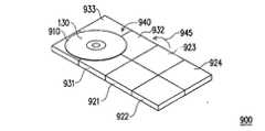
図35〜40は、本発明の第9実施例の光ディスクドライブのハウジングの変形を例示した複数の斜視図である。この第9実施例におけるカバー板および保持板は、この第9実施例に従って配置することができる。図35〜40を参照すると、光ディスクドライブ900は主ケース910、カバー板921〜924および保持板931〜933を有している。光ディスクドライブ900がコンパクトディスク130のデータを読み込む必要がない時、光ディスクドライブ900は、例えば、図35に示すように小型化することができる。光ディスクドライブ900がコンパクトディスク130のデータを読み込む必要がある時、主ケース910、カバー板921、922、および保持板931は矢印941の方向に沿って折り返される(図36参照)。そして、カバー板921〜924および保持板931、932が、主ケース910および保持板931〜933によって共に保持平面940を形成するために、矢印942の方向に沿って折り返される(図37参照)。次に、カバー板921〜924が矢印943の方向に沿って折り返される(図38参照)。そして、カバー板922と923とが矢印944の方向に沿って折り返されて、主ケース910、カバー板921〜924および保持板931〜933が完全に伸ばされる(図39参照)。その後、コンパクトディスク130が保持平面940上に配置され、主ケース910とカバー板921〜924と保持板931〜933とによって共にコンパクトディスク130を覆うためにカバー板921〜924が矢印945の方向に沿って折り返される(図40参照)。 35 to 40 are a plurality of perspective views illustrating modifications of the housing of the optical disk drive of the ninth embodiment of the invention. The cover plate and the holding plate in the ninth embodiment can be arranged according to the ninth embodiment. Referring to FIGS. 35 to 40, the
上記説明に基づけば、第9実施例の主な意図は、光ディスクドライブを小型化するために、複数の折り畳み板を折り込むことにある。光ディスクドライブがコンパクトディスクに書き込まれたデータを読み込む必要がある時、折り畳み板は、その折り畳み板と主ケースとの間の相対運動によって、コンパクトディスクを折り畳み板と主ケースとの両方に相互に収容させることができる。折り畳み板と主ケースとの間の相対運動は前記方法に限られない。その代わり、あらゆる運動方法が、コンパクトディスクを折り畳み板と主ケースとの両方に相互に収容させることができる限り、第9実施例によって定義された範囲に含まれる。 Based on the above description, the main intention of the ninth embodiment is to fold a plurality of folding plates in order to reduce the size of the optical disk drive. When the optical disk drive needs to read the data written on the compact disc, the folding plate can accommodate the compact disc in both the folding plate and the main case by the relative movement between the folding plate and the main case. Can be made. The relative movement between the folding plate and the main case is not limited to the above method. Instead, all methods of movement are included in the range defined by the ninth embodiment as long as the compact disc can be accommodated in both the folding plate and the main case.
要約すると、本発明の光ディスクドライブは、ハウジングを2つの部品、すなわち主ケースおよび可動ケースに分割する。光ディスクドライブがコンパクトディスクに書き込まれたデータを読み込む必要がない時、可動ケースはその機構設計によって光ディスクドライブの体積を減少させることができる。光ディスクドライブがコンパクトディスクに書き込まれたデータを読み込む必要がある時、可動ケースは、コンパクトディスクを主ケースおよび可動ケース両方に収容させるのに十分大きい空間を形成するために、主ケースから独立に拡張することができる。更に、上記実施例において記述された可動ケースの機構設計は、可動ケースの設計を限定することを意図するものではない。上記実施例の意図に従えば、上記複数の実施例における機械的設計の組み合わせを採用することができ、主ケースまたは可動ケースの一部または全ては、他の本体に統合されることも可能である。 In summary, the optical disk drive of the present invention divides the housing into two parts: a main case and a movable case. When the optical disk drive does not need to read data written on the compact disk, the movable case can reduce the volume of the optical disk drive by its mechanical design. When the optical disc drive needs to read the data written on the compact disc, the movable case expands independently from the main case to form a space large enough to accommodate the compact disc in both the main case and the movable case can do. Furthermore, the mechanism design of the movable case described in the above embodiments is not intended to limit the design of the movable case. In accordance with the intent of the above embodiment, a combination of mechanical designs in the above embodiments can be adopted, and a part or all of the main case or the movable case can be integrated into another main body. is there.
本発明の範囲または精神から逸脱することなく、本発明の構造に対して様々な改良および変更ができるということは、当業者にとって明らかである。前述の点を考慮し、本発明は、特許請求の範囲の請求項およびそれらの等価物の範囲に入ることを条件に、本発明の改良および変更をその範囲に含む。 It will be apparent to those skilled in the art that various modifications and variations can be made to the structure of the present invention without departing from the scope or spirit of the invention. In light of the foregoing, the present invention includes modifications and variations of the present invention provided that they fall within the scope of the appended claims and their equivalents.
かくして本発明の光ディスクドライブによればその体積を可動ハウジング機構によって小型化できる。 Thus, according to the optical disk drive of the present invention, the volume can be reduced by the movable housing mechanism.
100,200,300,400,500,500’,
500”,600,700,800,900 光ディスクドライブ
110,210,310,410,
510,510”,610,710 ハウジング
112,220,320,420,520,520”,
620,720,810,910 主ケース
114,230,330,430,530,530”、630,730 可動ケース100, 200, 300, 400, 500, 500 ′,
500 ", 600, 700, 800, 900
510, 510 ", 610, 710
620, 720, 810, 910
Claims (14)
Translated fromJapaneseコンパクトディスクを固定するために使用されるダンパと、そのダンパの近くに配置され、コンパクトディスクのデータを読み込むために使用される光ピックアップとを有する光ピックアップモジュールと、
前記光ピックアップモジュールに接続されコンパクトディスクの一部を保持するのに適した主ケースと、その主ケースに統合され可動ケースと主ケースとの両方によってコンパクトディスクを相互に収容させるためにその主ケースに対して相対運動をするのに適した前記可動ケースとを有する、前記光ピックアップモジュールに接続されたハウジングと、
を具えてなる光ディスクドライブ。An optical disc drive for reading compact disc data,
An optical pickup module having a damper used for fixing the compact disk and an optical pickup disposed near the damper and used for reading data of the compact disk;
A main case connected to the optical pickup module and suitable for holding a part of the compact disc, and a main case integrated with the main case for accommodating the compact disc by the movable case and the main case. A housing connected to the optical pickup module, the housing having a movable case suitable for relative movement with respect to
An optical disc drive comprising
Applications Claiming Priority (1)
| Application Number | Priority Date | Filing Date | Title |
|---|---|---|---|
| TW094102104ATWI257087B (en) | 2005-01-25 | 2005-01-25 | Optical disk driver |
Publications (1)
| Publication Number | Publication Date |
|---|---|
| JP2006209948Atrue JP2006209948A (en) | 2006-08-10 |
Family
ID=36698564
Family Applications (1)
| Application Number | Title | Priority Date | Filing Date |
|---|---|---|---|
| JP2006015153AWithdrawnJP2006209948A (en) | 2005-01-25 | 2006-01-24 | Optical disk drive |
Country Status (3)
| Country | Link |
|---|---|
| US (1) | US20060168606A1 (en) |
| JP (1) | JP2006209948A (en) |
| TW (1) | TWI257087B (en) |
Cited By (26)
| Publication number | Priority date | Publication date | Assignee | Title |
|---|---|---|---|---|
| JP2009157996A (en)* | 2007-12-26 | 2009-07-16 | Teac Corp | Disk device and electronic device |
| JP2010044805A (en)* | 2008-08-08 | 2010-02-25 | Sharp Corp | Optical disk cartridge |
| JP2010140548A (en)* | 2008-12-11 | 2010-06-24 | Sony Corp | Electronic apparatus |
| US9186136B2 (en) | 2009-12-09 | 2015-11-17 | Covidien Lp | Surgical clip applier |
| US9358011B2 (en) | 2008-08-29 | 2016-06-07 | Covidien Lp | Endoscopic surgical clip applier with connector plate |
| US9358015B2 (en) | 2008-08-29 | 2016-06-07 | Covidien Lp | Endoscopic surgical clip applier with wedge plate |
| US9364240B2 (en) | 2004-10-08 | 2016-06-14 | Covidien Lp | Endoscopic surgical clip applier |
| US9364239B2 (en) | 2011-12-19 | 2016-06-14 | Covidien Lp | Jaw closure mechanism for a surgical clip applier |
| US9393024B2 (en) | 2010-02-25 | 2016-07-19 | Covidien Lp | Articulating endoscopic surgical clip applier |
| US9398917B2 (en) | 2007-03-26 | 2016-07-26 | Covidien Lp | Endoscopic surgical clip applier |
| US9408610B2 (en) | 2012-05-04 | 2016-08-09 | Covidien Lp | Surgical clip applier with dissector |
| US9414844B2 (en) | 2008-08-25 | 2016-08-16 | Covidien Lp | Surgical clip appliers |
| US9439654B2 (en) | 2008-08-29 | 2016-09-13 | Covidien Lp | Endoscopic surgical clip applier |
| US9480477B2 (en) | 2006-10-17 | 2016-11-01 | Covidien Lp | Apparatus for applying surgical clips |
| US9498227B2 (en) | 2007-04-11 | 2016-11-22 | Covidien Lp | Surgical clip applier |
| US9526501B2 (en) | 2009-12-15 | 2016-12-27 | Covidien Lp | Surgical clip applier |
| US9532787B2 (en) | 2012-05-31 | 2017-01-03 | Covidien Lp | Endoscopic clip applier |
| US9549741B2 (en) | 2008-08-25 | 2017-01-24 | Covidien Lp | Surgical clip applier and method of assembly |
| US9642627B2 (en) | 2010-11-02 | 2017-05-09 | Covidien Lp | Self-centering clip and jaw |
| US9687247B2 (en) | 2004-10-08 | 2017-06-27 | Covidien Lp | Apparatus for applying surgical clips |
| US9717505B2 (en) | 2010-07-28 | 2017-08-01 | Covidien Lp | Articulating clip applier cartridge |
| US9737310B2 (en) | 2010-07-28 | 2017-08-22 | Covidien Lp | Articulating clip applier |
| US9750500B2 (en) | 2013-01-18 | 2017-09-05 | Covidien Lp | Surgical clip applier |
| US9763668B2 (en) | 2004-10-08 | 2017-09-19 | Covidien Lp | Endoscopic surgical clip applier |
| US9775624B2 (en) | 2013-08-27 | 2017-10-03 | Covidien Lp | Surgical clip applier |
| US9775623B2 (en) | 2011-04-29 | 2017-10-03 | Covidien Lp | Surgical clip applier including clip relief feature |
- 2005
- 2005-01-25TWTW094102104Apatent/TWI257087B/ennot_activeIP Right Cessation
- 2006
- 2006-01-19USUS11/336,563patent/US20060168606A1/ennot_activeAbandoned
- 2006-01-24JPJP2006015153Apatent/JP2006209948A/ennot_activeWithdrawn
Cited By (52)
| Publication number | Priority date | Publication date | Assignee | Title |
|---|---|---|---|---|
| US9687247B2 (en) | 2004-10-08 | 2017-06-27 | Covidien Lp | Apparatus for applying surgical clips |
| US9763668B2 (en) | 2004-10-08 | 2017-09-19 | Covidien Lp | Endoscopic surgical clip applier |
| US10349950B2 (en) | 2004-10-08 | 2019-07-16 | Covidien Lp | Apparatus for applying surgical clips |
| US9364240B2 (en) | 2004-10-08 | 2016-06-14 | Covidien Lp | Endoscopic surgical clip applier |
| US10485538B2 (en) | 2004-10-08 | 2019-11-26 | Covidien Lp | Endoscopic surgical clip applier |
| US10166027B2 (en) | 2006-10-17 | 2019-01-01 | Covidien Lp | Apparatus for applying surgical clips |
| US9480477B2 (en) | 2006-10-17 | 2016-11-01 | Covidien Lp | Apparatus for applying surgical clips |
| US10363045B2 (en) | 2007-03-26 | 2019-07-30 | Covidien Lp | Endoscopic surgical clip applier |
| US9398917B2 (en) | 2007-03-26 | 2016-07-26 | Covidien Lp | Endoscopic surgical clip applier |
| US10258346B2 (en) | 2007-04-11 | 2019-04-16 | Covidien Lp | Surgical clip applier |
| US9498227B2 (en) | 2007-04-11 | 2016-11-22 | Covidien Lp | Surgical clip applier |
| JP2009157996A (en)* | 2007-12-26 | 2009-07-16 | Teac Corp | Disk device and electronic device |
| JP2010044805A (en)* | 2008-08-08 | 2010-02-25 | Sharp Corp | Optical disk cartridge |
| US11510682B2 (en) | 2008-08-25 | 2022-11-29 | Covidien Lp | Surgical clip applier and method of assembly |
| US9549741B2 (en) | 2008-08-25 | 2017-01-24 | Covidien Lp | Surgical clip applier and method of assembly |
| US9414844B2 (en) | 2008-08-25 | 2016-08-16 | Covidien Lp | Surgical clip appliers |
| US10542999B2 (en) | 2008-08-25 | 2020-01-28 | Covidien Lp | Surgical clip applier and method of assembly |
| US11806021B2 (en) | 2008-08-29 | 2023-11-07 | Covidien Lp | Endoscopic surgical clip applier with wedge plate |
| US9545254B2 (en) | 2008-08-29 | 2017-01-17 | Covidien Lp | Endoscopic surgical clip applier with connector plate |
| US9439654B2 (en) | 2008-08-29 | 2016-09-13 | Covidien Lp | Endoscopic surgical clip applier |
| US11213298B2 (en) | 2008-08-29 | 2022-01-04 | Covidien Lp | Endoscopic surgical clip applier with wedge plate |
| US9358015B2 (en) | 2008-08-29 | 2016-06-07 | Covidien Lp | Endoscopic surgical clip applier with wedge plate |
| US10682135B2 (en) | 2008-08-29 | 2020-06-16 | Covidien Lp | Endoscopic surgical clip applier |
| US9358011B2 (en) | 2008-08-29 | 2016-06-07 | Covidien Lp | Endoscopic surgical clip applier with connector plate |
| US10231735B2 (en) | 2008-08-29 | 2019-03-19 | Covidien Lp | Endoscopic surgical clip applier |
| US10231738B2 (en) | 2008-08-29 | 2019-03-19 | Covidien Lp | Endoscopic surgical clip applier with wedge plate |
| US10159484B2 (en) | 2008-08-29 | 2018-12-25 | Covidien Lp | Endoscopic surgical clip applier with connector plate |
| US8336064B2 (en) | 2008-12-11 | 2012-12-18 | Sony Corporation | Electronic apparatus for driving an optical disc and having a reduced size and/or thickness |
| JP2010140548A (en)* | 2008-12-11 | 2010-06-24 | Sony Corp | Electronic apparatus |
| US9186136B2 (en) | 2009-12-09 | 2015-11-17 | Covidien Lp | Surgical clip applier |
| US10470765B2 (en) | 2009-12-15 | 2019-11-12 | Covidien Lp | Surgical clip applier |
| US9526501B2 (en) | 2009-12-15 | 2016-12-27 | Covidien Lp | Surgical clip applier |
| US10271854B2 (en) | 2010-02-25 | 2019-04-30 | Covidien Lp | Articulating endoscopic surgical clip applier |
| US9393024B2 (en) | 2010-02-25 | 2016-07-19 | Covidien Lp | Articulating endoscopic surgical clip applier |
| US11213299B2 (en) | 2010-02-25 | 2022-01-04 | Covidien Lp | Articulating endoscopic surgical clip applier |
| US9737310B2 (en) | 2010-07-28 | 2017-08-22 | Covidien Lp | Articulating clip applier |
| US11517322B2 (en) | 2010-07-28 | 2022-12-06 | Covidien Lp | Articulating clip applier |
| US9717505B2 (en) | 2010-07-28 | 2017-08-01 | Covidien Lp | Articulating clip applier cartridge |
| US10568635B2 (en) | 2010-07-28 | 2020-02-25 | Covidien Lp | Articulating clip applier |
| US9642627B2 (en) | 2010-11-02 | 2017-05-09 | Covidien Lp | Self-centering clip and jaw |
| US9775623B2 (en) | 2011-04-29 | 2017-10-03 | Covidien Lp | Surgical clip applier including clip relief feature |
| US9364239B2 (en) | 2011-12-19 | 2016-06-14 | Covidien Lp | Jaw closure mechanism for a surgical clip applier |
| US9855043B2 (en) | 2011-12-19 | 2018-01-02 | Covidien Lp | Jaw closure mechanism for a surgical clip applier |
| US9408610B2 (en) | 2012-05-04 | 2016-08-09 | Covidien Lp | Surgical clip applier with dissector |
| US10660639B2 (en) | 2012-05-04 | 2020-05-26 | Covidien Lp | Surgical clip applier with dissector |
| US11026696B2 (en) | 2012-05-31 | 2021-06-08 | Covidien Lp | Endoscopic clip applier |
| US10159492B2 (en) | 2012-05-31 | 2018-12-25 | Covidien Lp | Endoscopic clip applier |
| US9532787B2 (en) | 2012-05-31 | 2017-01-03 | Covidien Lp | Endoscopic clip applier |
| US10537329B2 (en) | 2013-01-18 | 2020-01-21 | Covidien Lp | Surgical clip applier |
| US9750500B2 (en) | 2013-01-18 | 2017-09-05 | Covidien Lp | Surgical clip applier |
| US10682146B2 (en) | 2013-08-27 | 2020-06-16 | Covidien Lp | Surgical clip applier |
| US9775624B2 (en) | 2013-08-27 | 2017-10-03 | Covidien Lp | Surgical clip applier |
Also Published As
| Publication number | Publication date |
|---|---|
| TW200627402A (en) | 2006-08-01 |
| US20060168606A1 (en) | 2006-07-27 |
| TWI257087B (en) | 2006-06-21 |
Similar Documents
| Publication | Publication Date | Title |
|---|---|---|
| JP2006209948A (en) | Optical disk drive | |
| JP7474783B2 (en) | Portable communication device including hinge structure | |
| US9183862B1 (en) | Load/unload ramps for multiple disk-stack, shared actuator hard disk drive | |
| CN101334684B (en) | Electronic apparatus | |
| US20040004785A1 (en) | Front panel assembly of disk drive having door locking means and disk drive incorporating the same | |
| JP2008210476A (en) | Disk drive device and ramp member used therefor | |
| CN103582372A (en) | Portable electronic device and electronic module fixing structure thereof | |
| TWI220755B (en) | Optical disc device | |
| JP4777430B2 (en) | Compact and portable optical disk drive | |
| TWI457919B (en) | Built-in disk driver and related computer device | |
| US8381994B2 (en) | Data storage device, stacking method thereof, and data storage device assembly | |
| EP1688953A2 (en) | Optical disk drive | |
| JP2006179148A (en) | Disk drive device | |
| JP2010140548A (en) | Electronic apparatus | |
| CN100595838C (en) | optical recording media cartridge | |
| JP2006185485A (en) | Disk drive device | |
| TWI353596B (en) | Optical recording and reproducing device | |
| JPH05346829A (en) | Computer | |
| CN101740094A (en) | Portable disc | |
| JP2008310906A (en) | Disk recording and/or reproduction apparatus | |
| US8032901B2 (en) | Disk device and electronic apparatus | |
| CN102592622A (en) | CD player | |
| JP4896492B2 (en) | Disk unit | |
| CN100487812C (en) | Disc cartridge | |
| JP2002025215A (en) | Magnetic disk cartridge |
Legal Events
| Date | Code | Title | Description |
|---|---|---|---|
| A300 | Application deemed to be withdrawn because no request for examination was validly filed | Free format text:JAPANESE INTERMEDIATE CODE: A300 Effective date:20090407 |