JP2006209770A - Apparatus and method for generating position and map of moving body, and computer-readable recording medium storing computer program for controlling the apparatus - Google Patents
Apparatus and method for generating position and map of moving body, and computer-readable recording medium storing computer program for controlling the apparatusDownload PDFInfo
- Publication number
- JP2006209770A JP2006209770AJP2006016141AJP2006016141AJP2006209770AJP 2006209770 AJP2006209770 AJP 2006209770AJP 2006016141 AJP2006016141 AJP 2006016141AJP 2006016141 AJP2006016141 AJP 2006016141AJP 2006209770 AJP2006209770 AJP 2006209770A
- Authority
- JP
- Japan
- Prior art keywords
- landmark
- video
- candidate
- upper image
- unit
- Prior art date
- Legal status (The legal status is an assumption and is not a legal conclusion. Google has not performed a legal analysis and makes no representation as to the accuracy of the status listed.)
- Granted
Links
Images


Classifications
- G—PHYSICS
- G05—CONTROLLING; REGULATING
- G05D—SYSTEMS FOR CONTROLLING OR REGULATING NON-ELECTRIC VARIABLES
- G05D1/00—Control of position, course, altitude or attitude of land, water, air or space vehicles, e.g. using automatic pilots
- G05D1/02—Control of position or course in two dimensions
- G05D1/021—Control of position or course in two dimensions specially adapted to land vehicles
- G05D1/0231—Control of position or course in two dimensions specially adapted to land vehicles using optical position detecting means
- G05D1/0246—Control of position or course in two dimensions specially adapted to land vehicles using optical position detecting means using a video camera in combination with image processing means
- G05D1/0253—Control of position or course in two dimensions specially adapted to land vehicles using optical position detecting means using a video camera in combination with image processing means extracting relative motion information from a plurality of images taken successively, e.g. visual odometry, optical flow
- G—PHYSICS
- G05—CONTROLLING; REGULATING
- G05D—SYSTEMS FOR CONTROLLING OR REGULATING NON-ELECTRIC VARIABLES
- G05D3/00—Control of position or direction
- G—PHYSICS
- G05—CONTROLLING; REGULATING
- G05D—SYSTEMS FOR CONTROLLING OR REGULATING NON-ELECTRIC VARIABLES
- G05D1/00—Control of position, course, altitude or attitude of land, water, air or space vehicles, e.g. using automatic pilots
- G05D1/02—Control of position or course in two dimensions
- G05D1/021—Control of position or course in two dimensions specially adapted to land vehicles
- G05D1/0268—Control of position or course in two dimensions specially adapted to land vehicles using internal positioning means
- G05D1/0272—Control of position or course in two dimensions specially adapted to land vehicles using internal positioning means comprising means for registering the travel distance, e.g. revolutions of wheels
- G—PHYSICS
- G05—CONTROLLING; REGULATING
- G05D—SYSTEMS FOR CONTROLLING OR REGULATING NON-ELECTRIC VARIABLES
- G05D1/00—Control of position, course, altitude or attitude of land, water, air or space vehicles, e.g. using automatic pilots
- G05D1/02—Control of position or course in two dimensions
- G05D1/021—Control of position or course in two dimensions specially adapted to land vehicles
- G05D1/0268—Control of position or course in two dimensions specially adapted to land vehicles using internal positioning means
- G05D1/0274—Control of position or course in two dimensions specially adapted to land vehicles using internal positioning means using mapping information stored in a memory device
- H—ELECTRICITY
- H04—ELECTRIC COMMUNICATION TECHNIQUE
- H04N—PICTORIAL COMMUNICATION, e.g. TELEVISION
- H04N5/00—Details of television systems
- H04N5/76—Television signal recording
- H04N5/91—Television signal processing therefor
Landscapes
- Engineering & Computer Science (AREA)
- Physics & Mathematics (AREA)
- Radar, Positioning & Navigation (AREA)
- General Physics & Mathematics (AREA)
- Automation & Control Theory (AREA)
- Aviation & Aerospace Engineering (AREA)
- Remote Sensing (AREA)
- Multimedia (AREA)
- Electromagnetism (AREA)
- Computer Vision & Pattern Recognition (AREA)
- Signal Processing (AREA)
- Image Analysis (AREA)
- Instructional Devices (AREA)
- Control Of Position, Course, Altitude, Or Attitude Of Moving Bodies (AREA)
Abstract
Translated fromJapaneseDescription
Translated fromJapanese本発明は、移動体の位置推定及び地図の生成装置とその方法、並びにその装置を制御するコンピュータプログラムを保存するコンピュータで読み取り可能な記録媒体に関する。 The present invention relates to a mobile object position estimation and map generation apparatus and method, and a computer-readable recording medium storing a computer program for controlling the apparatus.
従来、ロボットの地図生成方法は、スキャンマッチング(scan matching)方式を利用して非常に正確な地図が得られるが、地図を獲得するためにレーザーレンジファインダー(laser range finder)のような非常に高価なセンサーを要求するという問題点がある。このような従来の方法の一つが、非特許文献1に発表された論文に開示されている。ここに開示された従来の方法は、レーザーレンジファインダーの他にも、天井映像(ceiling images)を利用して地図を生成する方法を提案しているが、天井映像を全て完全に保存せねばならないため、多くの演算量を要求するだけでなく、ロボットの位置認識及び地図生成を同時に行えないという問題点がある。従来の方法の他の一つが、非特許文献2に発表された論文に開示されている。ここに開示された従来の方法は、主に野外で使用されるように考案された方法であり、地図作成及び位置認識を同時に行えるが、それはまた、高価なレーザーレンジファインダーを利用するという問題点がある。さらに他の従来の方法が、非特許文献3に発表された論文及び特許文献1に開示されている。ここに開示された従来の方法も、ロボットの位置認識及び地図生成を同時に行えないという問題点を有する。 Traditionally, robot map generation methods use a scan matching method to obtain a very accurate map, but it is very expensive to obtain a map, such as a laser range finder. There is a problem of requiring a new sensor. One such conventional method is disclosed in a paper published in Non-Patent
また、従来、ロボットの位置を認識すると共に地図を生成する方法が、非特許文献4に発表された論文に開示されている。ここに、開示された従来の方法は、照明に敏感に影響を受けるという問題点を有する。さらに他の従来の方法が、非特許文献5に発表された論文に開示されている。ここに開示された従来の方法は、2台のカメラを利用せねばならないだけではなく、照明の変化にも敏感であり、位置及び地図を正確に認識して生成できないという問題点を有する。
上述のように、非特許文献1の方法では、天井映像を用いることでより演算量が多くなり、ロボットの位置認識及び地図生成を同時に行えない。また、非特許文献2の方法では、地図作成及び位置認識を同時に行えるが、高価なレーザーレンジファインダーが必要となってしまう。非特許文献3及び特許文献1の方法では、ロボットの位置認識及び地図生成を同時に行えないという問題点を有する。非特許文献4の方法では、地図作成及び位置認識を同時に行えるが、照明に対して敏感に影響を受けて位置及び地図を正確に認識して生成できない。さらに、非特許文献5の方法では、2台のカメラを利用せねばならないだけではなく、照明の変化にも敏感であり、位置及び地図を正確に認識して生成できない。 As described above, in the method of Non-Patent
そこで、本発明が達成しようとする技術的課題は、移動体の位置を正確に認識するとともに地図作成を正確に行うことが可能な移動体の位置推定及び地図の生成装置、その方法、並びにその装置を制御するコンピュータプログラムを保存するコンピュータで読み取り可能な記録媒体を提供するところにある。 Therefore, the technical problem to be achieved by the present invention is to provide a mobile object position estimation and map generation apparatus, its method, and its method capable of accurately recognizing the position of the mobile object and accurately creating a map. The object of the present invention is to provide a computer-readable recording medium for storing a computer program for controlling the apparatus.
前記課題を達成するための本願第1発明による上部(upper)映像を利用した移動体の位置推定及び地図の生成装置は、移動体の位置した環境の上部を撮影して獲得した上部映像でコーナーを表すコーナー点を観測し、観測されたコーナー点からランドマークを生成するランドマーク生成部、及び前記ランドマークから前記移動体の位置を推定して地図を生成する位置及び地図演算部から構成されることが好ましい。 According to the first aspect of the present invention for achieving the above object, the moving object position estimation and map generation apparatus using the upper image captures the upper image obtained by photographing the upper part of the environment where the moving object is located. A landmark generation unit that observes a corner point that represents the position, and generates a landmark from the observed corner point, and a position that generates a map by estimating the position of the moving object from the landmark and a map calculation unit It is preferable.
コーナー点を観測してランドマークを生成するため、上部映像そのものを保存したり演算することなくランドマークを生成することができ、演算量を減らすことができる。演算量が減少するため、生成したランドマークからの位置の推定及び地図の作成をともに行うことが可能となる。
また、カメラなどを用いて上部映像を取得することでランドマークを生成するため、レーザーレンジファインダーのような高価なカメラが不要である。このとき、上部映像を取得するために、安価の一台のカメラのみを利用すれば良いため、製造コストを低減させることができる。Since the landmark is generated by observing the corner point, the landmark can be generated without saving or calculating the upper video itself, and the amount of calculation can be reduced. Since the amount of calculation decreases, it is possible to both estimate the position from the generated landmark and create a map.
Further, since the landmark is generated by acquiring the upper image using a camera or the like, an expensive camera such as a laser range finder is unnecessary. At this time, since it is sufficient to use only one inexpensive camera in order to acquire the upper image, the manufacturing cost can be reduced.
上述の通り、ランドマークは、上部映像に基づいて自動的に生成される。よって、例えば、赤外線ランドマーク、色パターンのような人工ランドマークなどの別途の付着物によりランドマークを生成する必要がない。このような別途の付着物によるランドマークを用いた場合には、これらのランドマークをセンシングする際に、照明などの影響を受けてランドマークを正確に取得することが出来ない場合がある。しかし、本発明のように、上部映像に基づいてランドマークを生成する場合には、前述のような照明の影響を受けることが無く正確にランドマークを生成でき、正確な位置の推定及び正確な地図作製を行うことができる。 As described above, the landmark is automatically generated based on the upper image. Therefore, for example, it is not necessary to generate the landmarks by separate deposits such as infrared landmarks and artificial landmarks such as color patterns. In the case where landmarks due to such extraneous matter are used, there are cases where the landmarks cannot be obtained accurately due to the influence of lighting or the like when sensing these landmarks. However, when the landmark is generated based on the upper image as in the present invention, the landmark can be generated accurately without being affected by the illumination as described above, and the accurate position estimation and accurate You can make a map.
第2発明は、第1発明において、前記ランドマーク生成部は、現在上部映像で、前記コーナー点の座標及び前記コーナー点を互いに区分する映像特徴周辺記述子のうち、少なくとも一つを利用して観測した前記コーナー点のうち、以前上部映像でランドマークやランドマーク候補であったコーナー点を見つけ、以前上部映像でランドマークでもなくランドマーク候補でもなかった前記コーナー点を新たなランドマーク候補として登録し、前記ランドマーク候補のうち、所定回数以上前記コーナー点として観測されたランドマーク候補をランドマークとして登録し、前記現在上部映像は、現在獲得された前記上部映像に該当し、前記以前上部映像とは、以前に獲得された前記上部映像に該当することを特徴とする上部映像を利用した移動体の位置推定及び地図の生成装置を提供する。 In a second aspect based on the first aspect, the landmark generation unit uses at least one of the coordinates of the corner point and the video feature peripheral descriptor that distinguishes the corner point from each other in the current upper image. Of the observed corner points, find a corner point that was previously a landmark or landmark candidate in the upper video, and use the corner point that was not a landmark or landmark candidate in the upper video as a new landmark candidate. The landmark candidates that are observed as the corner points more than a predetermined number of times are registered as landmarks, and the current upper image corresponds to the currently acquired upper image, and the previous upper image is registered. The video is the position of the moving object using the upper video, which corresponds to the upper video acquired previously. Providing estimation and generation device map.
コーナー点や映像特徴周辺記述子を用いてランドマークを生成するため、上部映像そのものを用いる場合よりも大幅に演算量を削減することができる。
ランドマークの候補を新たに登録する時、コーナー点の特徴を表すSIFT(Scale Invariant Feature Transform)記述子のような映像特徴周辺記述子を利用する場合には、移動体の位置した室内環境の全体の照度が変化するとしても、映像の輝度変化は一定である。よって、移動体の位置した照明の変化にロバスト性を有するランドマークを見つけて登録できる。これにより移動体の位置認識及び地図作成を正確に行わせることができる。例えば、移動体の平均距離誤差を約6cm以内に維持し、方位角の平均誤差を約2度以内に維持できる。ここで、ロバスト性とは,外乱や設計誤差などの不確定な変動に対して,システム特性が現状を維持できることを意味する。Since landmarks are generated using corner points and video feature peripheral descriptors, the amount of computation can be greatly reduced as compared with the case of using the upper video itself.
When a landmark candidate is newly registered, when an image feature peripheral descriptor such as a SIFT (Scale Invariant Feature Transform) descriptor representing the feature of a corner point is used, the entire indoor environment where the moving object is located is used. Even if the illuminance changes, the luminance change of the image is constant. Therefore, landmarks that are robust to changes in illumination where the moving body is located can be found and registered. Thereby, the position recognition and map creation of a moving body can be performed correctly. For example, the average distance error of the moving body can be maintained within about 6 cm, and the average azimuth angle error can be maintained within about 2 degrees. Here, robustness means that the current system characteristics can be maintained against uncertain fluctuations such as disturbances and design errors.
第3発明は、第2発明において、前記上部映像を利用した移動体の位置推定及び地図の生成装置は、前記移動体の走行を制御し、前記走行についての情報を出力する走行処理部をさらに備え、前記位置及び地図演算部は、前記走行処理部から入力した前記走行についての情報と、前記ランドマーク生成部から入力した前記ランドマークとから移動体の位置を推定し、かつ地図を生成し、前記ランドマークについての情報を前記ランドマーク生成部に出力することを特徴とする上部映像を利用した移動体の位置推定及び地図の生成装置を提供する。 According to a third aspect, in the second aspect, the mobile object position estimation and map generation device using the upper image further includes a travel processing unit that controls travel of the mobile body and outputs information about the travel. The position and map calculation unit estimates the position of the moving body from the information about the travel input from the travel processing unit and the landmark input from the landmark generation unit, and generates a map An apparatus for estimating the position of a moving object and generating a map using an upper image is provided, wherein information about the landmark is output to the landmark generation unit.
位置及び地図演算部は、走行処理部からの走行についての情報を取得することで、移動体の位置を正確に取得し、また正確な地図を生成することができる。
第4発明は、第2発明において、前記ランドマーク生成部は、前記移動体の位置した環境の上部映像を獲得する映像獲得部と、前記映像獲得部から入力した前記獲得された映像をバッファリングし、バッファリングされた結果を前記以前上部映像として出力する映像バッファと、前記映像獲得部で現在獲得された前記現在上部映像のコーナー点の座標及び前記映像特徴周辺記述子のうち、少なくとも一つを映像特徴情報として抽出する映像特徴情報抽出部と、前記以前上部映像での前記ランドマーク及び前記ランドマーク候補を、前記現在上部映像で予測するランドマーク及びランドマーク候補予測部と、前記予測ランドマーク及びランドマーク候補についての情報と前記映像特徴情報とを比較し、比較された結果により前記コーナー点のうち、以前上部映像でランドマークやランドマーク候補であったコーナー点を観測して見つけ、前記以前上部映像で前記ランドマークでもなく、前記ランドマーク候補でもなかった前記コーナー点を新たなランドマーク候補として登録する観測及び登録部と、前記ランドマーク候補のうち、所定回数以上前記コーナー点として観測されたランドマーク候補を、前記ランドマークとして登録するランドマーク登録部と、を備えることを特徴とする上部映像を利用した移動体の位置推定及び地図の生成装置を提供する。The position and map calculation unit can acquire the position of the moving body accurately and can generate an accurate map by acquiring information about the travel from the travel processing unit.
According to a fourth aspect, in the second aspect, the landmark generation unit buffers the acquired image input from the image acquisition unit, and an image acquisition unit that acquires an upper image of the environment where the moving object is located. And at least one of a video buffer for outputting the buffered result as the previous upper video, the coordinates of the corner point of the current upper video currently acquired by the video acquisition unit, and the video feature peripheral descriptor. A video feature information extraction unit that extracts video feature information as a video feature information; a landmark and landmark candidate prediction unit that predicts the landmark and landmark candidate in the previous upper video; and the predicted land The information about the mark and landmark candidate is compared with the video feature information, and the corner point is detected based on the comparison result. , By observing and finding a corner point that was previously a landmark or landmark candidate in the upper video, and using the corner point that was not the landmark or the landmark candidate in the previous upper video as a new landmark candidate An upper part comprising: an observation and registration unit to be registered; and a landmark registration unit that registers, as the landmark, a landmark candidate that is observed as the corner point more than a predetermined number of times among the landmark candidates Provided is a moving object position estimation and map generation apparatus using video.
現在上部映像のコーナー点を随時検出し、そのコーナー点のうち、以前上部映像でランドマーク及びランドマーク候補でもなかったコーナー点を新たなランドマーク候補として登録することで、随時新たなランドマークを生成することができる。
第5発明は、第4発明において、前記映像獲得部は、前記移動体の位置した環境の前記上部映像を獲得する上部映像獲得部と、前記獲得された上部映像の歪曲を補正する歪曲補正部と、を備えることを特徴とする。By detecting corner points of the current upper video as needed and registering corner points that were not previously landmarks and landmark candidates in the upper video as new landmark candidates. Can be generated.
According to a fifth invention, in the fourth invention, the video acquisition unit includes an upper video acquisition unit that acquires the upper video of the environment in which the moving object is located, and a distortion correction unit that corrects distortion of the acquired upper video. And.
第6発明は、第4発明において、前記映像獲得部は、前記移動体の位置した環境の前記上部映像を獲得する上部映像獲得部と、前記獲得された上部映像を低域通過フィルタリングする低域通過フィルタと、を備えることを特徴とする上部映像を利用した移動体の位置推定及び地図の生成装置を提供する。
第7発明は、第5発明において、前記映像獲得部は、前記歪曲が補正された結果を低域通過フィルタリングする低域通過フィルタをさらに備えることを特徴とする上部映像を利用した移動体の位置推定及び地図の生成装置を提供する。According to a sixth aspect of the present invention based on the fourth aspect, the video acquisition unit includes an upper video acquisition unit that acquires the upper video of the environment in which the moving object is located, and a low frequency that performs low-pass filtering on the acquired upper video A moving body position estimation and map generation apparatus using an upper image, characterized by comprising a pass filter.
According to a seventh aspect of the present invention, in the fifth aspect, the video acquisition unit further includes a low-pass filter that performs low-pass filtering on the result of correcting the distortion. An estimation and map generation device is provided.
第8発明は、第5発明において、前記歪曲補正部は、前記獲得された上部映像で関心領域を設定し、設定された関心領域のみに対して前記歪曲を補正することを特徴とする上部映像を利用した移動体の位置推定及び地図の生成装置を提供する。
設定された関心領域のみに対して歪曲を補正することで、演算量を削減することができる。According to an eighth aspect of the present invention, in the fifth aspect, the distortion correction unit sets a region of interest in the acquired upper image, and corrects the distortion only for the set region of interest. A mobile body position estimation and map generation apparatus using the above is provided.
The amount of calculation can be reduced by correcting the distortion only for the set region of interest.
第9発明は、第4発明において、前記映像特徴情報抽出部は、前記現在上部映像で前記コーナー点を検出し、前記検出されたコーナー点の座標を出力するコーナー点検出部と、前記検出されたコーナー点の周辺に映像を分析し、前記分析された結果から前記コーナー点別に前記映像特徴周辺記述子を演算する記述子演算部と、を備えることを特徴とする上部映像を利用した移動体の位置推定及び地図の生成装置を提供する。 According to a ninth aspect of the present invention based on the fourth aspect, the video feature information extracting unit detects the corner point in the current upper video, and outputs the detected corner point coordinates, and the detected corner point detection unit. A moving object using an upper image, comprising: a descriptor calculation unit that analyzes a video around a corner point and calculates the video feature peripheral descriptor for each corner point from the analyzed result A position estimation and map generation apparatus is provided.
第10発明は、第9発明において、前記コーナー点検出部は、下記式のR値が0より大きく、R値が局所最大点となる点を前記コーナー点として決定することを特徴とする上部映像を利用した移動体の位置推定及び地図の生成装置を提供する According to a tenth aspect of the present invention, in the ninth aspect, the corner point detection unit determines, as the corner point, a point where the R value of the following formula is greater than 0 and the R value is a local maximum point. A mobile object position estimation and map generation device using

第11発明は、第10発明において、前記kは、0.04であることを特徴とする上部映像を利用した移動体の位置推定及び地図の生成装置を提供する。
第12発明は、第9発明において、前記記述子演算部で演算される前記映像特徴周辺記述子は、スケール不変特徴変換記述子であることを特徴とする請求項9に記載の上部映像を利用した移動体の位置推定及び地図の生成装置を提供する。An eleventh aspect of the present invention provides the apparatus for estimating the position of a moving body and generating a map using the upper image, wherein the k is 0.04 in the tenth aspect.
The twelfth invention uses the upper picture according to the ninth invention, wherein the picture feature peripheral descriptor computed by the descriptor computing unit is a scale invariant feature conversion descriptor. An apparatus for estimating the position of a moving body and generating a map is provided.
スケール不変特徴変換(SIFT:Scale Invariant Feature Transform)記述子を用いることで、コーナー点の周辺の映像の輝度変化分布などを利用してコーナー点の特徴を表現することができる。
第13発明は、第4発明において、前記ランドマーク及びランドマーク候補予測部は、前記以前上部映像で登録された前記ランドマーク及び前記ランドマーク候補の位置の3次元座標を、前記以前上部映像が入力された時の前記移動体の位置及び方位角を利用して、前記以前上部映像の映像座標系を基準に2次元に変換する映像座標変換部と、前記映像座標変換部から入力した変換された2次元座標を有する前記ランドマーク及び前記ランドマーク候補のうち、前記以前上部映像に属する前記ランドマーク及び前記ランドマーク候補のみを選択する選択部と、前記映像獲得部から入力した前記現在上部映像と、前記映像バッファから入力した前記以前上部映像との間の変化量を、前記選択された結果について計算し、前記計算された変化量を利用して、前記現在上部映像にある前記ランドマーク及び前記ランドマーク候補を予測する位置予測部と、を備えることを特徴とする上部映像を利用した移動体の位置推定及び地図の生成装置を提供する。By using a scale invariant feature transform (SIFT) descriptor, the feature of a corner point can be expressed using a luminance change distribution of an image around the corner point.
In a thirteenth aspect based on the fourth aspect, the landmark and landmark candidate predicting unit is configured to display a three-dimensional coordinate of the position of the landmark and the landmark candidate registered in the previous upper video, Using the position and azimuth of the moving body when input, a video coordinate conversion unit that converts two-dimensionally based on the video coordinate system of the previous upper image, and a conversion input from the video coordinate conversion unit Among the landmarks having two-dimensional coordinates and the landmark candidates, a selection unit that selects only the landmarks and the landmark candidates that belong to the previous upper video, and the current upper video input from the video acquisition unit And the amount of change between the previous upper image input from the image buffer for the selected result and calculating the amount of change A position prediction unit for predicting the landmark and the landmark candidate in the current upper video, and providing a mobile object position estimation and map generation device using the upper video To do.
第14発明は、第13発明において、前記位置予測部は、オプティカルフロートラッカーを利用して、前記現在上部映像にある前記ランドマーク及び前記ランドマーク候補の位置を予測することを特徴とする上部映像を利用した移動体の位置推定及び地図の生成装置を提供する。
オプティカルフロートラックキングと映像特徴周辺記述子とを何れも利用する場合には、従来のSLAM技法の問題であるデータ関連問題、すなわち、Large closed loop問題を解決でき、EKF基盤のSLAM(Simultaneous Location And Map Building)技法の安定性を確保できる。In a fourteenth aspect based on the thirteenth aspect, the position predicting unit predicts the positions of the landmarks and the landmark candidates in the current upper image using an optical flow tracker. A mobile body position estimation and map generation apparatus using the above is provided.
When both the optical flow tracking and the video feature peripheral descriptor are used, the data-related problem that is the problem of the conventional SLAM technique, that is, the large closed loop problem can be solved, and an EKF-based SLAM (Simultaneous Location And The stability of the Map Building) technique can be ensured.
第15発明は、第4発明において、前記観測及び登録部は、前記コーナー点のそれぞれに対して、前記コーナー点と最も近い予測ランドマークやランドマーク候補を探すランドマーク及びランドマーク候補検索部と、前記コーナー点のそれぞれに対して、前記コーナー点と前記検出されたランドマークやランドマーク候補との間の距離を計算する第1距離計算部と、前記第1距離計算部で計算された距離と第1所定距離とを比較する第1比較部と、前記第1比較部で比較された結果に応答して、前記コーナー点の映像特徴周辺記述子と、前記検出されたランドマークやランドマーク候補の映像特徴周辺記述子との間の距離を計算する第2距離計算部と、前記第2距離計算部で計算された距離と第2所定距離とを比較する第2比較部と、前記第2比較部で比較された結果に応答して、前記コーナー点と最も近い位置に前記ランドマークが存在するか、それとも前記ランドマーク候補が存在するかを識別するランドマーク及びランドマーク候補識別部と、前記識別された結果に応答して、前記ランドマークが観測された回数を表すランドマークフラグをアッパーカウンティングするか、前記ランドマーク候補が観測された回数を表すランドマーク候補フラグをアッパーカウンティングするカウンターと、前記第1比較部及び前記第2比較部で比較された結果に応答して、前記コーナー点のうち、前記以前上部映像で前記ランドマークでもなく、前記ランドマーク候補でもなかったコーナー点を、前記新たなランドマーク候補として見つけ、検出された前記新たなランドマーク候補についての情報を登録するランドマーク候補初期化部と、を備えることを特徴とする上部映像を利用した移動体の位置推定及び地図の生成装置を提供する。 In a fifteenth aspect based on the fourth aspect, the observation and registration unit includes a landmark and a landmark candidate search unit for searching for a predicted landmark or landmark candidate closest to the corner point for each of the corner points. A first distance calculation unit that calculates a distance between the corner point and the detected landmark or landmark candidate for each of the corner points, and a distance calculated by the first distance calculation unit And a first comparison unit that compares the first predetermined distance with the first comparison unit, and in response to the comparison result of the first comparison unit, the video feature peripheral descriptor of the corner point, and the detected landmark or landmark A second distance calculating unit that calculates a distance between candidate video feature peripheral descriptors; a second comparing unit that compares a distance calculated by the second distance calculating unit with a second predetermined distance; In response to the result of comparison by the comparison unit, a landmark and a landmark candidate identification unit for identifying whether the landmark is present at a position closest to the corner point or whether the landmark candidate is present; In response to the identified result, a counter that counts a landmark flag that represents the number of times that the landmark has been observed, or a counter that counts the landmark candidate flag that represents the number of times that the landmark candidate has been observed, and In response to the result of comparison in the first comparison unit and the second comparison unit, out of the corner points, the corner points that were not the landmarks and the landmark candidates in the previous upper image are: The new landmark candidate is found and detected as the new landmark candidate. Providing position estimation and apparatus for generating a map of a moving body utilizing a upper image, characterized in that it comprises a landmark candidate initializing unit for registering the information.
第16発明は、第4発明において、前記ランドマーク生成部は、前記登録されたランドマーク候補のうち、互いに重複しているランドマーク候補を除去し、重複していないランドマーク候補等の2次元映像座標から3次元映像座標を推定するランドマーク候補処理部をさらに備え、前記ランドマーク登録部は、前記重複していないランドマーク候補のうち、前記所定回数以上前記コーナー点として観測されたランドマーク候補を前記ランドマークとして登録することを特徴とする上部映像を利用した移動体の位置推定及び地図の生成装置を提供する。 In a sixteenth aspect based on the fourth aspect, the landmark generation unit removes overlapping landmark candidates from the registered landmark candidates, and provides a two-dimensional representation such as non-overlapping landmark candidates. A landmark candidate processing unit that estimates 3D video coordinates from video coordinates, wherein the landmark registration unit is a landmark that has been observed as the corner point more than the predetermined number of times among the non-overlapping landmark candidates; A mobile object position estimation and map generation apparatus using an upper video, wherein candidates are registered as the landmarks.
第17発明は、第16発明において、前記ランドマーク候補処理部は、前記登録されたランドマーク候補のそれぞれに対して、最も近いランドマーク候補間の最小距離を計算する第3距離計算部と、前記各最小距離と第3所定距離とを比較する第3比較部と、前記第3比較部で比較された結果に応答して、前記各ランドマーク候補が重複しているか否かを決定し、決定された結果に相応して、重複しているランドマーク候補を除去するランドマーク候補除去部と、前記第3比較部で比較された結果に応答して、前記重複していないランドマーク候補の3次元映像座標を推定する座標推定部と、を備えることを特徴とする上部映像を利用した移動体の位置推定及び地図の生成装置を提供する。 In a sixteenth aspect based on the sixteenth aspect, the landmark candidate processing unit calculates a minimum distance between nearest landmark candidates for each of the registered landmark candidates, In response to the result of the comparison between the third comparison unit and the third comparison unit that compares the minimum distance with a third predetermined distance, it is determined whether or not the landmark candidates overlap. According to the determined result, in response to the result of comparison between the landmark candidate removing unit that removes the overlapping landmark candidate and the third comparing unit, A position estimation unit for a moving object and a map generation device using an upper image, comprising: a coordinate estimation unit that estimates a three-dimensional image coordinate.
第18発明は、第1発明において、前記位置及び地図演算部は、拡張されたカルマンフィルタを利用して、前記ランドマークから前記移動体の前記位置を推定し、かつ前記地図を生成することを特徴とする上部映像を利用した移動体の位置推定及び地図の生成装置を提供する。
前記他の課題を達成するための本願第19発明による上部映像を利用した移動体の位置推定及び地図生成方法は、移動体の位置した環境の上部を撮影して獲得した上部映像でコーナーを表すコーナー点を観測し、観測されたコーナー点からランドマークを生成するステップ、及び前記ランドマークから前記移動体の位置を推定して地図を生成するステップからなることが好ましい。In an eighteenth aspect based on the first aspect, the position and map calculation unit estimates the position of the moving object from the landmark and generates the map using an extended Kalman filter. A mobile object position estimation and map generation apparatus using the upper video is provided.
According to the nineteenth aspect of the present invention for achieving the other object, the moving object position estimation and map generation method using the upper image represents a corner in the upper image obtained by photographing the upper part of the environment where the moving object is located. Preferably, the method includes a step of observing a corner point, generating a landmark from the observed corner point, and generating a map by estimating the position of the moving body from the landmark.
第20発明は、第19発明において、前記(a)ステップは、現在上部映像で前記コーナー点の座標及び前記コーナー点を互い区分させる映像特徴周辺記述子のうち、少なくとも一つを利用して、前記コーナー点のうち、以前上部映像でランドマークやランドマーク候補であったコーナー点を観測し、以前上部映像でランドマークでもなくランドマーク候補でもなかった前記コーナー点を新たなランドマーク候補として登録し、前記ランドマーク候補のうち、所定回数以上前記コーナー点として観測されたランドマーク候補をランドマークとして登録し、前記現在上部映像は、現在獲得された前記上部映像に該当し、前記以前上部映像は、以前に獲得された前記上部映像に該当することを特徴とする上部映像を利用した移動体の位置推定及び地図生成方法を提供する。 In a twentieth aspect based on the nineteenth aspect, the step (a) uses at least one of the coordinates of the corner points and the video feature peripheral descriptors that distinguish the corner points from each other in the current upper video, Observe the corner points that were previously landmarks and landmark candidates in the upper video, and register the corner points that were neither landmarks nor landmark candidates in the upper video as new landmark candidates. Among the landmark candidates, the landmark candidates observed as the corner points a predetermined number of times or more are registered as landmarks, and the current upper image corresponds to the currently acquired upper image, and the previous upper image Is a position estimation of a moving object using the upper image, and corresponds to the previously acquired upper image, and It provides a view generation method.
第21発明は、第20発明において、前記(a)ステップは、前記移動体の位置した環境の上部映像を獲得するステップと、前記獲得された映像をバッファリングし、バッファリングされた結果を前記以前上部映像として決定するステップと、前記現在上部映像のコーナー点の座標及び前記映像特徴周辺記述子のうち、少なくとも一つを映像特徴情報として抽出するステップと、前記以前上部映像での前記ランドマーク及び前記ランドマーク候補を前記現在上部映像で予測するステップと、前記予測ランドマーク及びランドマーク候補についての情報と前記映像特徴情報とを比較し、比較された結果を利用して、前記コーナー点のうち、以前上部映像でランドマークやランドマーク候補であったコーナー点を観測して見つけ、前記以前上部映像で前記ランドマークでもなく、前記ランドマーク候補でもなかった前記コーナー点を新たなランドマーク候補として登録するステップと、前記ランドマーク候補のうち、所定回数以上前記コーナー点として観測されたランドマーク候補を前記ランドマークとして登録するステップと、を含むことを特徴とする上部映像を利用した移動体の位置推定及び地図生成方法を提供する。 In a twenty-first aspect based on the twentieth aspect, in the step (a), the step (a) acquires an upper image of the environment in which the moving object is located, buffers the acquired image, and displays the buffered result as the buffer. A step of determining as a previous upper image, a step of extracting at least one of the coordinates of a corner point of the current upper image and the image feature peripheral descriptor as image feature information, and the landmark in the previous upper image And predicting the landmark candidate with the current upper image, comparing the information about the predicted landmark and the landmark candidate with the video feature information, and using the compared result, Among them, by observing and finding the corner points that were previously landmarks and landmark candidates in the upper video, Registering the corner point that is neither the landmark nor the landmark candidate as a new landmark candidate, and among the landmark candidates, the landmark candidate that has been observed as the corner point a predetermined number of times or more. And a step of registering the landmark as a landmark, and a method of estimating the position of a moving object and generating a map using an upper video.
第22発明は、第21発明において、前記映像を獲得するステップは、前記移動体の位置した環境の前記上部映像を獲得するステップと、前記獲得された上部映像の歪曲を補正するステップと、を含むことを特徴とする記載の上部映像を利用した移動体の位置推定及び地図生成方法を提供する。
第23発明は、第21発明において、前記映像を獲得するステップは、前記移動体の位置した環境の前記上部映像を獲得するステップと、前記獲得された上部映像を低域通過フィルタリングするステップと、を含むことを特徴とする上部映像を利用した移動体の位置推定及び地図生成方法を提供する。According to a twenty-second aspect, in the twenty-first aspect, the step of acquiring the image includes the step of acquiring the upper image of the environment where the moving object is located, and correcting the distortion of the acquired upper image. The present invention provides a method for estimating the position of a moving object and generating a map using the upper image described above.
In a twenty-third aspect based on the twenty-first aspect, the step of acquiring the image includes the step of acquiring the upper image of the environment in which the moving object is located, the step of performing low-pass filtering on the acquired upper image, The present invention provides a method for estimating the position of a moving object and generating a map using an upper image.
第24発明は、第22発明において、前記映像を獲得するステップは、前記歪曲が補正された結果を低域通過フィルタリングするステップをさらに含むことを特徴とする上部映像を利用した移動体の位置推定及び地図生成方法。
第25発明は、第21発明において、前記映像特徴情報を抽出するステップは、前記現在上部映像で前記コーナー点を検出し、前記検出されたコーナー点の座標を求めるステップと、前記検出されたコーナー点の周辺に映像を分析し、前記分析された結果を利用して、前記コーナー点別に前記映像特徴周辺記述子を求めるステップと、を含むことを特徴とする上部映像を利用した移動体の位置推定及び地図生成方法を提供する。According to a twenty-fourth aspect of the invention, in the twenty-second aspect, the step of acquiring the image further includes a step of low-pass filtering the result of correcting the distortion. And map generation method.
In a twenty-fifth aspect based on the twenty-first aspect, the step of extracting the video feature information includes a step of detecting the corner point in the current upper video and obtaining coordinates of the detected corner point, and the detected corner Analyzing the video around a point, and using the analyzed result to obtain the video feature peripheral descriptor for each corner point, and the position of the moving body using the upper video, An estimation and map generation method is provided.
第26発明は、第21発明において、前記ランドマーク及び前記ランドマーク候補の位置を前記現在上部映像で予測するステップは、前記以前上部映像で登録された前記ランドマーク及び前記ランドマーク候補の位置の3次元座標を、前記以前上部映像が入力された時の前記移動体の位置及び方位角を利用して、前記以前上部映像の映像座標系を基準に2次元に変換するステップと、前記変換された2次元座標を有する前記ランドマーク及び前記ランドマーク候補のうち、前記以前上部映像に属する前記ランドマーク及び前記ランドマーク候補のみを選択するステップと、前記現在上部映像と前記以前上部映像との間の変化量を、前記選択された結果について計算し、前記計算された変化量を利用して、前記現在上部映像にある前記ランドマーク及び前記ランドマーク候補を予測するステップと、を含むことを特徴とする上部映像を利用した移動体の位置推定及び地図生成方法。 According to a twenty-sixth aspect of the present invention, in the twenty-first aspect, the step of predicting the positions of the landmarks and the landmark candidates in the current upper image includes the positions of the landmarks and the landmark candidates registered in the previous upper image. Converting the three-dimensional coordinates into two dimensions using the position and azimuth of the moving body when the previous upper image is input, based on the image coordinate system of the previous upper image; and Selecting only the landmark and the landmark candidate belonging to the previous upper image among the landmark and the landmark candidate having two-dimensional coordinates, and between the current upper image and the previous upper image For the selected result, and using the calculated amount of change, the landma in the current upper image is calculated. Position estimation and map generation method of a moving body utilizing a upper image, characterized in that it comprises the steps of predicting a click and the landmark candidate, the.
第27発明は、第21発明において、前記コーナー点を観測して、前記新たなランドマーク候補を登録するステップは、前記コーナー点のそれぞれに対して、前記コーナー点と最も近い予測ランドマークやランドマーク候補を探すステップと、前記コーナー点のそれぞれに対して、前記コーナー点と前記検出されたランドマークやランドマーク候補との間の距離が第1所定距離以下であるか否かを判断するステップと、前記コーナー点と前記検出されたランドマークやランドマーク候補との距離が前記第1所定距離以下であるコーナー点のそれぞれに対して、前記コーナー点の映像特徴周辺記述子と、前記検出されたランドマークやランドマーク候補の映像特徴周辺記述子との間の距離が第2所定距離以下であるか否かを判断するステップと、前記コーナー点の映像特徴周辺記述子と、前記検出されたランドマークやランドマーク候補の映像特徴周辺記述子との間の距離が前記第2所定距離以下であると判断されれば、前記コーナー点と最も近い位置に前記ランドマークが存在するか、それとも前記ランドマーク候補が存在するかを判断するステップと、前記ランドマークが存在すると判断されれば、前記ランドマークが観測された回数を表すランドマークフラグをアッパーカウンティングするステップと、前記ランドマーク候補が存在すると判断されれば、前記ランドマーク候補が観測された回数を表すランドマーク候補フラグをアッパーカウンティングするステップと、前記検出されたランドマークやランドマーク候補及び前記第1所定距離より遠く位置したコーナー点、または前記検出されたランドマークやランドマーク候補の映像特徴周辺記述子及び前記第2所定距離より遠く位置した前記映像特徴周辺記述子に該当するコーナー点を、前記新たなランドマーク候補として決定し、決定された前記新たなランドマーク候補についての情報を登録するステップと、を含むことを特徴とする上部映像を利用した移動体の位置推定及び地図生成方法を提供する。 According to a twenty-seventh aspect, in the twenty-first aspect, the step of observing the corner point and registering the new landmark candidate is a predicted landmark or land nearest to the corner point for each of the corner points. A step of searching for a mark candidate and a step of determining whether a distance between the corner point and the detected landmark or landmark candidate is equal to or less than a first predetermined distance for each of the corner points. And a video feature peripheral descriptor of the corner point for each corner point whose distance between the corner point and the detected landmark or landmark candidate is equal to or less than the first predetermined distance, and the detected Determining whether or not the distance between the landmark and the landmark candidate video feature peripheral descriptor is equal to or less than a second predetermined distance; If it is determined that the distance between the video feature peripheral descriptor of the corner point and the detected video feature peripheral descriptor of the landmark or landmark candidate is equal to or less than the second predetermined distance, the corner point Determining whether the landmark is present at the closest position or whether the landmark candidate is present, and if it is determined that the landmark is present, a land representing the number of times the landmark has been observed. A mark flag upper counting step, and if it is determined that the landmark candidate exists, a step of upper counting a landmark candidate flag indicating the number of times the landmark candidate is observed, and the detected landmark or A landmark candidate and a corner point located farther than the first predetermined distance, or A corner point corresponding to the detected video feature peripheral descriptor of the landmark or landmark candidate and the video feature peripheral descriptor positioned farther than the second predetermined distance is determined as the new landmark candidate and determined. And registering information about the new landmark candidate that has been made, and providing a method for estimating the position of a moving object and generating a map using an upper image.
第28発明は、第21発明において、前記(a)ステップは、前記登録されたランドマーク候補のうち、互いに重複しているランドマーク候補を除去し、重複していないランドマーク候補の2次元映像座標から3次元映像座標を推定するステップをさらに備えることを特徴とする上部映像を利用した移動体の位置推定及び地図生成方法を提供する。
第29発明は、第28発明において、前記映像座標を推定するステップは、前記登録されたランドマーク候補のそれぞれに対して、最も近いランドマーク候補間の最小距離を求めるステップと、前記最小距離が第3所定距離以下であるか否かを判断するステップと、前記第3所定距離以下の最小距離を有するランドマーク候補は互いに重複していると決定し、重複しているランドマーク候補を除去するステップと、前記第3所定距離より遠く離れた最小距離を有するランドマーク候補は互いに重複していないと決定し、前記重複していないランドマーク候補の3次元映像座標を推定するステップと、を含むことを特徴とする上部映像を利用した移動体の位置推定及び地図生成方法を提供する。In a twenty-eighth aspect based on the twenty-first aspect, in the step (a), in the registered landmark candidates, landmark candidates that overlap each other are removed, and a two-dimensional image of the landmark candidates that do not overlap each other is removed. A method for estimating a position of a moving object and a map generation method using an upper image, further comprising a step of estimating a three-dimensional image coordinate from the coordinate.
In a twenty-ninth aspect based on the twenty-eighth aspect, the step of estimating the video coordinates includes obtaining a minimum distance between nearest landmark candidates for each of the registered landmark candidates, The step of determining whether or not the distance is equal to or less than a third predetermined distance and the landmark candidates having the minimum distance equal to or less than the third predetermined distance are determined to overlap each other, and the overlapping landmark candidates are removed. And determining that landmark candidates having a minimum distance farther than the third predetermined distance do not overlap with each other, and estimating three-dimensional video coordinates of the non-overlapping landmark candidates. A moving object position estimation and map generation method using an upper image characterized by the above is provided.
前記さらに他の課題を達成するためのコンピュータプログラムを保存するコンピュータで読み取り可能な記録媒体は、発明19〜20のいずれかに記載の上部映像を利用した移動体の位置推定及び地図生成方法を実行するコンピュータプログラムを保存する。 A computer-readable recording medium storing a computer program for achieving the further another object executes the position estimation and map generation method of the moving body using the upper image according to any of the inventions 19 to 20. Save the computer program.
本発明によれば、移動体の位置を正確に認識するとともに地図作成を正確に行うことが可能な移動体の位置推定及び地図の生成装置、その方法、並びにその装置を制御するコンピュータプログラムを保存するコンピュータで読み取り可能な記録媒体を提供することができる。 ADVANTAGE OF THE INVENTION According to this invention, the position estimation and map generation apparatus of the moving body which can recognize the position of a moving body correctly, and can perform map creation correctly, its method, and the computer program which controls the apparatus are preserve | saved A computer-readable recording medium can be provided.
以下、添付した図面を参照して、本発明による上部(upper)映像を利用した移動体の位置推定及び地図の生成装置及びその装置の実施形態のそれぞれの構成と動作、並びにその装置と、その実施形態で行われる上部映像を利用した移動体の位置推定及び地図生成の方法とを説明すれば、次の通りである。
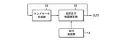
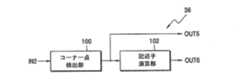
図1は、本発明による上部映像を利用して、移動体の位置を推定し、かつ移動体周辺の地図を生成するための装置に係る実施形態のブロック図である。図1に示す装置は、ランドマーク生成部10、位置及び地図演算部12及び走行処理部14から構成される。Hereinafter, with reference to the accompanying drawings, according to the present invention, the structure and operation of a mobile object position estimation and map generation apparatus using the upper image and the embodiment of the apparatus, and the apparatus, A method for estimating the position of a moving body and generating a map using the upper image performed in the embodiment will be described as follows.
FIG. 1 is a block diagram of an embodiment of an apparatus for estimating a position of a moving object and generating a map around the moving object using an upper image according to the present invention. The apparatus shown in FIG. 1 includes a
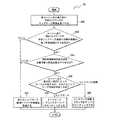
図2は、本発明による上部映像を利用した移動体の位置推定及び地図生成方法の実施形態を説明するためのフローチャートである。図2に示すフローチャートは、ランドマーク(landmark)を生成するステップ(ステップ20)及び位置を推定して地図を生成するステップ(ステップ22)からなる。
図1に示すランドマーク生成部10は、上部映像でコーナー点を観測し、観測されたコーナー点から、目印や境界線となるランドマークを生成する(ステップ20)。この時、ランドマークは、自動的に生成されうる。FIG. 2 is a flowchart for explaining an embodiment of a method for estimating a position of a moving object and a map generation method using an upper image according to the present invention. The flowchart shown in FIG. 2 includes a step of generating a landmark (step 20) and a step of generating a map by estimating the position (step 22).
The
本発明によれば、ステップ20でランドマーク生成部10は、現在の上部映像から観測されたコーナー点の座標及び映像特徴周辺記述子(Local Feature Descriptor:以下、LFD)のうち、少なくとも一つを利用して、観測されたコーナー点のうち以前の上部映像でランドマークやランドマーク候補であったコーナー点を検出する。そして、現在の上部映像のうち、以前の上部映像でランドマークやランドマーク候補ではなかったコーナー点を新たなランドマーク候補として登録する。さらに、既に登録されたランドマーク候補のうち、所定回数以上コーナー点として観測されたランドマーク候補をランドマークとして登録し、登録されたランドマークを位置及び地図演算部12に出力する(ステップ20)。 According to the present invention, in
ここで、コーナー点とは、上部映像においてコーナーを表す点を意味し、LFDとは、コーナー点の周辺映像を分析した結果を利用して、コーナー点そのものの特徴を表すデータであって、コーナー点を互いに区分する役割を行う。上部映像とは、移動体(図示せず)のある室内環境の上部に対して、移動体に付着された、上部を見渡すカメラ(図示せず)で獲得された映像を意味する。現在上部映像とは、現在、獲得された上部映像を意味し、以前上部映像とは、以前に獲得して、後述される図3に示す映像バッファ32に保存された映像を意味する。ここで、上部に対して獲得された映像は、移動体の位置した室内環境の天井だけでなく、その天井に隣接した壁面も含みうる。移動体とは、ロボットのように、映像を撮影しつつ移動できる物体を意味する。また、ランドマークとは、現在の上部映像のうち、以前の上部映像でランドマークやランドマーク候補ではなかったコーナー点が、所定回数以上ランドマーク候補として登録されたものである。一方、ランドマーク候補とは、所定回数未満しか登録されていないものである。 Here, the corner point means a point representing the corner in the upper image, and the LFD is data representing the characteristics of the corner point itself using the result of analyzing the peripheral video of the corner point. It plays the role of distinguishing points from each other. The upper image means an image acquired by a camera (not shown) attached to the moving body and looking over the upper part of the indoor environment where the moving body (not shown) is present. The current upper video means the currently acquired upper video, and the previous upper video means the video that has been previously acquired and stored in the
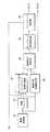
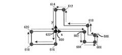
図3は、図1に示すランドマーク生成部10の本発明による好ましい実施形態10Aのブロック図であって、映像獲得部30、映像バッファ32、ランドマーク及びランドマーク候補予測部34、映像特徴情報抽出部36、観測及び登録部38、ランドマーク候補処理部40及びランドマーク登録部42から構成される。
図4は、図2に示すステップ20についての本発明による実施形態20Aを説明するためのフローチャートであって、上部映像を獲得してバッファリングするステップ(ステップ50、52)、映像特徴情報を抽出して、以前のランドマーク及びランドマーク候補を、現在上部映像に基づいて予測するステップ(ステップ54、56)、新たなランドマーク候補を登録して、以前のランドマーク及びランドマーク候補を管理するステップ(ステップ58)、及びランドマーク候補を処理して、該当するランドマーク候補をランドマークとして登録するステップ(ステップ60、62)からなる。FIG. 3 is a block diagram of a preferred embodiment 10A of the
FIG. 4 is a flowchart for explaining the embodiment 20A according to the present invention for
図3に示す映像獲得部30は、移動体が位置している環境の上部映像を獲得し、獲得した映像を映像バッファ32、ランドマーク及びランドマーク候補予測部34及び映像特徴情報抽出部36にそれぞれ出力する(ステップ50)。
図5は、図3に示す映像獲得部30の本発明による実施形態30Aのブロック図であって、上部映像獲得部70、歪曲補正部72及び低域通過フィルタ74から構成される。The
FIG. 5 is a block diagram of an embodiment 30A of the
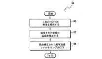
図6は、図4に示すステップ50についての本発明による実施形態50Aを説明するためのフローチャートであって、上部映像を獲得するステップ(ステップ80)。及び映像の歪曲を補正して低域通過フィルタリングを行うステップ(ステップ82、84)からなる。
本発明の一実施形態によれば、上部映像獲得部70は、移動体が位置している環境の上部映像を獲得し、獲得した映像を歪曲補正部72に出力する(ステップ80)。FIG. 6 is a flowchart for explaining the embodiment 50A according to the present invention for the
According to an embodiment of the present invention, the upper
ステップ80の後に、歪曲補正部72は、上部映像獲得部70で獲得された上部映像の歪曲を補正し、歪曲が補正された結果を低域通過フィルタ74に出力する(ステップ82)。本発明によれば、演算量を減らすために、歪曲補正部72は、上部映像獲得部70で獲得された上部映像で関心領域(ROI:Region Of Interest)を設定し、設定されたROIのみに対して歪曲を補正してもよい。つまり、着目する領域を限定することで、演算量を削減する。 After
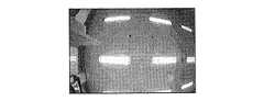
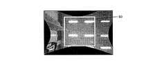
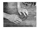
図7Aは、歪曲補正部72に入力される映像の一例を示し、図7Bは、歪曲補正部72から出力される映像の一例を示す。
例えば、移動体の上部に装着されうる上部映像獲得部70が、移動体の位置した環境の上部でさらに広い領域の映像を獲得するために、広角カメラ(図示せず)及び魚眼レンズカメラ(図示せず)で具現される場合、上部映像獲得部70で獲得される映像は、例えば、図7Aに示すように歪曲される。したがって、歪曲補正部72は、図7Aに示すような歪曲された映像を入力して歪曲を補正し、歪曲が補正された結果である図7Bに示す映像を出力する。この時、前記のように演算量を減らすために、歪曲補正部72は、図7Bに示すような限定された領域のROI 90のみに対して歪曲を補正することもできる。7A shows an example of an image input to the
For example, an upper
映像歪曲補正に対しては、‘S.Shah’及び‘J.K.Aggarwal’、“A simple calibration procedure for fish−eye(high distortion) lens camera”、IEEE International Conf.on Robotics and Automationのvol.4,May 1994、pp.のページ3422〜3427に掲載された論文に開示されている。 For video distortion correction, 'S. Shah 'and' J. K. Aggarwal ', "A simple calibration for fish-eye (high distortion) lens camera", IEEE International Conf. on Robotics and Automation, Vol. 4, May 1994, pp., pages 3422-3427.
ステップ82の後に、低域通過フィルタ74は、歪曲補正部72で歪曲が補正された結果から高周波成分のノイズを除去するために、歪曲が補正された結果を低域通過フィルタリングし、低域通過フィルタリングされた結果を出力端子OUT4を介して出力する(ステップ84)。このように、低域通過フィルタ74を利用して映像に含まれた高周波ノイズ成分を除去する場合、映像のスムージング効果を提供できる。このために、低域通過フィルタ74は、ガウスフィルタ(図示せず)で具現されうる。 After
例えば、3×3ガウスカーネルの場合、低域通過フィルタ74は、次の数式(1)のようなフィルタリングされた結果を、出力端子OUT4を介して出力する。 For example, in the case of a 3 × 3 Gaussian kernel, the low-
本発明のさらに他の実施形態によれば、図5に示すところとは違って、映像獲得部30は、上部映像獲得部70及び歪曲補正部72のみで具現できる。この場合、図6に示すところとは違って、ステップ50は、ステップ80及びステップ82のみで具現される。この時、歪曲補正部72で歪曲補正された結果は、映像バッファ32、ランドマーク及びランドマーク候補予測部34及び映像特徴情報抽出部36に出力される。 According to another exemplary embodiment of the present invention, unlike the example illustrated in FIG. 5, the
本発明のさらに他の実施形態によれば、図5に示すところとは違って、映像獲得部30は、上部映像獲得部70及び低域通過フィルタ74のみで具現できる。この場合、図6に示すところとは違って、ステップ50は、ステップ80及びステップ84のみで具現される。この時、低域通過フィルタ74は、上部映像獲得部70で獲得された上部映像を低域通過フィルタリングし、低域通過フィルタリングされた結果を出力端子OUT4を介して出力する(ステップ84)。 According to another exemplary embodiment of the present invention, unlike the example illustrated in FIG. 5, the
一方、ステップ50の後に、映像バッファ32は、映像獲得部30で獲得された映像をバッファリングし、バッファリングされた結果を以前上部映像としてランドマーク及びランドマーク候補予測部34に出力する(ステップ52)。すなわち、映像バッファ32は、現在上部映像を受信して記憶すると共に、直前の映像である以前上部映像を出力する。
ステップ52の後に、映像特徴情報抽出部36は、映像獲得部30で現在獲得された現在上部映像のコーナー点の座標及びLFDのうち、少なくとも一つを映像特徴情報として抽出し、抽出された映像特徴情報を観測及び登録部38に出力する(ステップ54)。On the other hand, after
After
図8は、図3に示す映像特徴情報抽出部36の本発明による実施形態36Aのブロック図であって、コーナー点検出部100及び記述子演算部102から構成される。
図9は、図4に示すステップS54についての本発明による実施形態54Aを説明するためのフローチャートであって、コーナー点を検出するステップ(ステップ110)及びLFDを求めるステップ(ステップ112)からなる。FIG. 8 is a block diagram of an embodiment 36A of the video feature
FIG. 9 is a flowchart for explaining the embodiment 54A according to the present invention for step S54 shown in FIG. 4, and includes a step of detecting corner points (step 110) and a step of obtaining LFD (step 112).
コーナー点検出部100は、入力端子IN2を介して、映像獲得部30から入力した現在上部映像でコーナー点を検出し、検出されたコーナー点の座標を記述子演算部102に出力する一方、出力端子OUT5を介して映像特徴情報として出力する(ステップ110)。
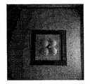
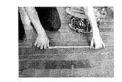
図10A及び図10Bは、コーナー点検出部100の理解を容易にするための写真であって、図10Aは、コーナー点検出部100に入力される映像の一例を示し、図10Bは、コーナー点検出部100で検出されたコーナー点を十字架状に示す。The corner
10A and 10B are photographs for facilitating understanding of the corner
本発明によれば、コーナー点検出部100は、多様な方法のうち最も性能の良いと知られた、例えば、ハリスコーナー点の検出法によりコーナー点を検出できる。ここで、ハリスコーナー点の検出法については、‘C.J.Harris’及び‘M.Stephens’、“A combined corner and edge detector”、In Proc.4th Alvey Vision Conf.,Manchester,1988、pp.147〜151に開示されている。この場合、例えば、コーナー点検出部100は、図10Aに示すような映像を入力して、図10Bに示すようにコーナー点を検出できる。 According to the present invention, the corner
例えば、ハリスコーナー点の検出法によれば、コーナー点検出部100は、次の数式(4)のように表現されるR値が0より大きく、R値が局所最大点となる点をコーナー点として決定できる。 For example, according to the Harris corner point detection method, the corner
ステップ110の後に、記述子演算部102は、コーナー点検出部100で検出されたコーナー点の周辺の映像を分析する。そして、分析された結果を利用して、コーナー点別にLFDを演算し、演算されたLFDを出力端子OUT6を介して映像特徴情報として出力する(ステップ112)。本発明によれば、記述子演算部102で演算されるLFDは、多様な記述子のうち、好ましくは、スケール不変特徴変換(SIFT:Scale Invariant Feature Transform)記述子を意味することもある。SIFT記述子は、コーナー点の周辺の映像の輝度変化分布などを利用してコーナー点の特徴を表現する。このために、記述子演算部102は、入力端子IN2を介して映像獲得部30から現在上部映像を入力し、コーナー点検出部100で検出されたコーナー点の座標を入力し、例えば、128バイトからなるLFDを出力する。
After
‘K.Mikolajczk’及び‘C.Schmid’、“A performance evaluation of local descriptors”、IEEE Conference on Computer Vision and Pattern Recognition,June 2003によれば、前記のSIFT記述子は、最も優れていると知られている。また、SIFT記述子の生成方法については、‘David G.Lowe’、“Distinctive image features from scale−invariant keypoints”、International Journal of Computer Vision,60,2(2004)、pp.91〜110に掲載された論文に開示されている。 'K. Mikolajczk 'and' C. According to Schmid ', "A performance evaluation of local descriptors", IEEE Conference on Computer Vision and Pattern Recognition, June 2003, the above-mentioned SIFT descriptor is the best known. For the method of generating the SIFT descriptor, 'David G. Low ', disclosed in a paper published in "Distinctive image features from scale-invariant keypoints", International Journal of Computer Vision, 60, 2 (2004), pp. 91-110.
一方、ステップ54の後に、ランドマーク及びランドマーク候補予測部34は、以前上部映像でのランドマーク及びランドマーク候補が、現在上部映像のどの位置にあるかを予測する。そして、現在上部映像で予測ランドマーク及びランドマーク候補の位置を、観測及び登録部38に出力する(ステップ56)。このような予測により、図3に示す観測及び登録部38は、現在上部映像に対して検出されたコーナー点のうち、以前にあらかじめ登録されたランドマーク及びランドマーク候補点であったコーナー点を見つけ得る。 On the other hand, after
一方、ランドマーク及びランドマーク候補予測部34では、映像が入力されるごとに予測が行われる。各映像で持続的に追従されたランドマーク候補点の場合、各映像での2次元映像座標軌跡と、映像が入力されるときの移動体の位置及び方位角とを保存する。保存されたそれらの情報は、ランドマーク候補点がランドマークとして登録される時、ランドマークの3次元座標値を推定可能にする。 On the other hand, the landmark and landmark
図3に示すランドマーク及びランドマーク候補予測部34は、図1に示す位置及び地図演算部12からランドマーク情報、移動体の位置及び移動体の方位角を入力端子IN1を介して受信する。そして、ランドマーク登録部42からランドマーク候補情報を受信し、映像バッファ32から以前上部映像を受信し、映像獲得部30から現在上部映像を受信する。ここで、ランドマーク情報は、ランドマークの位置、すなわち、基準座標系でランドマークに対する3次元座標及びランドマークに対するLFDを含む。ランドマーク候補情報は、ランドマーク候補の位置、すなわち、基準座標系でランドマーク候補に対する3次元座標及びランドマーク候補に対するLFDを含む。 The landmark and landmark
図11は、図3に示すランドマーク及びランドマーク候補予測部34の本発明による好ましい実施形態34Aのブロック図であって、映像座標変換部130、選択部132及び位置予測部134から構成される。
図12は、図4に示すステップ56についての本発明による好ましい実施形態56Aを説明するためのフローチャートであって、座標を変換するステップ(ステップ140)、ランドマーク及びランドマーク候補のうち、以前の映像に属するランドマーク及びランドマーク候補を選択するステップ(ステップ142)、及び現在上部映像でのランドマーク及びランドマーク候補の座標、すなわち、位置を予測するステップ(ステップ144)からなる。FIG. 11 is a block diagram of a preferred embodiment 34A of the landmark and landmark
FIG. 12 is a flow chart for explaining a preferred embodiment 56A according to the present invention for
ステップ54後に、映像座標変換部130は、以前上部映像を基準として以前にあらかじめ登録されたランドマーク及びランドマーク候補情報を、入力端子IN3を介して受信する。受信したランドマーク及びランドマーク候補情報にそれぞれ含まれる、ランドマーク及びランドマーク候補の位置の3次元座標を、以前上部映像が入力された時の移動体の位置及び移動体の方位角を利用して、以前上部映像の映像座標系を基準に2次元座標に変換する。そして、変換された2次元座標を有するランドマーク及びランドマーク候補情報を選択部132に出力する(ステップ140)。このために、移動体の位置及び移動体の方位角は、入力端子IN4を介して映像座標変換部130に入力される。 After
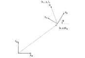
図13は、映像座標変換部130の動作を説明するための座標系を例示的に示す図面である。
図13に示すように、映像座標系で二つの座標軸xv、Yv(以下、vは、映像座標系を意味する添字である)が存在し、移動体座標系で二つの座標軸Xr、Yr(以下、rは、移動体座標系を意味する添字である)が存在し、基準座標系は三つの座標軸Xw、Yw、Zw(以下、wは、基準座標系を意味する添字である)で定義される。ここで、二つの車輪154及び156を有する移動体は、矢印152方向に進むと仮定し、移動体の位置座標は、基準座標系で(x、y、θ)wで表現される。ここで、x、yは、位置座標を表し、θは方位角を表す。この時、図13に示す破線で囲まれた参照符号150は、映像獲得部30で獲得された映像を、移動体が位置した物理的な空間上にカメラの撮像領域を考慮して仮想的に表示したものである。FIG. 13 is a view exemplarily showing a coordinate system for explaining the operation of the video coordinate
As shown in FIG. 13, there are two coordinate axes xv and Yv (hereinafter, v is a subscript meaning the video coordinate system) in the video coordinate system, and the two coordinate axes Xr , There exists Yr (hereinafter, r is a subscript meaning a moving body coordinate system), and the reference coordinate system has three coordinate axes Xw , Yw , Zw (hereinafter, w means the reference coordinate system). Subscript). Here, it is assumed that the moving body having the two
映像座標変換部130の入力端子IN3を介して入力されるランドマーク及びランドマーク候補情報にそれぞれ含まれるランドマーク及びランドマーク候補の位置は、図13に示す基準座標系を基準に3次元座標である(x、y、z)wで表示されうる。また、映像座標変換部130で変換されたランドマーク及びランドマーク候補の座標のそれぞれは、図13に示す映像座標系を基準とする2次元座標(x,y)vで表示されうる。ここで、vは、映像座標系を意味する添字である。The positions of the landmarks and landmark candidates included in the landmark and landmark candidate information input via the input terminal IN3 of the video coordinate
一方、ステップ140の後に、選択部132は、映像座標変換部130から受信した、変換された2次元座標を有するランドマーク及びランドマーク候補のうち、以前上部映像に属するランドマーク及びランドマーク候補のみを選択し、選択された結果を位置予測部134に出力する(ステップ142)。
図14は、図11に示す選択部132の理解を容易にするための図面であって、複数のランドマーク160、162、164、166、168及び170及び複数のランドマーク候補180、182、184及び186を表す。本発明の理解を容易にするために、図14でランドマーク及びランドマーク候補は、記号でもって区分して表示したが、本発明は、必ずしもこれに限定されるものではない。ここで、参照符号190及び192は、それぞれ以前上部映像190及び現在上部映像192である。On the other hand, after
FIG. 14 is a diagram for facilitating understanding of the
図14に示すように、選択部132は、変換された2次元座標を有するランドマーク160、162、164、166、168及び170とランドマーク候補180、182、184及び186のうち、以前上部映像190に属するランドマーク168とランドマーク候補184及び186のみを選択し、選択されたランドマーク168とランドマーク候補184及び186とについての情報を位置予測部134に出力する。 As illustrated in FIG. 14, the
ステップ142の後に、位置予測部134は、映像獲得部30から入力端子IN5を介して受信した現在上部映像と、映像バッファ32から入力端子IN6を介して受信した以前上部映像との間の変化量を、選択部132から受信した選択された結果、すなわち、選択された各ランドマーク及び選択された各ランドマーク候補から計算する。そして、計算された変化量を利用して、現在上部映像にあるランドマーク及びランドマーク候補の座標を予測し、予測結果を出力端子OUT7を介して観測及び登録部38に出力する(第144ステップ)。この時、選択部132で選択された結果及び位置予測部134で予測結果の座標のそれぞれは、映像座標系を基準とする2次元座標である。 After
図15は、位置予測部134の理解を容易にするための図面であって、以前上部映像190を獲得する時の移動体200と、現在上部映像192を獲得する時の移動体202とを示す。
図14及び図15に示すように、位置予測部134は、現在上部映像192と以前上部映像190との間の変化量を、選択部132で選択されたランドマーク168と選択されたランドマーク候補184及び186とのそれぞれについて計算する。そして、計算された変化量を利用して、現在上部映像192にあるランドマーク168とランドマーク候補184及び186とのそれぞれの座標を予測し、予測結果を出力端子OUT7を介して観測及び登録部38に出力する。FIG. 15 is a diagram for facilitating the understanding of the
As shown in FIGS. 14 and 15, the
本発明によれば、位置予測部134は、オプティカルフロートラッカーを利用して、現在上部映像にあるランドマーク及びランドマーク候補の位置を予測できる。ここで、オプティカルフローとは、現在上部映像と以前上部映像との間の輝度変化情報を利用して、映像の移動量及び回転量が分かる動きベクトルを意味する。オプティカルフロートラッカーとして広く知られたLukas−Kanadeオプティカルフロートラッカーについては、‘Lucas,B.’及び‘Kanade,T.’、“AnIterative Image Registration Technique with an Application to Stereo Vision”、Proc.of 7th International Joint Conference on Artificial Intelligence(IJCAI)、pp.674〜679に掲載された論文に開示されている。 According to the present invention, the
本発明によれば、図4に示すところとは違って、ステップ54及びステップ56は、同時に行われてもよく、ステップ56がステップ54より先に行われてもよい。
一方、ステップ56の後に、観測及び登録部38は、ランドマーク及びランドマーク候補予測部34で予測ランドマーク及びランドマーク候補についての情報と、映像特徴情報抽出部36から受信した映像特徴情報とを比較する。比較された結果を利用して、現在上部映像で検索されたコーナー点のうち、以前上部映像でランドマークやランドマーク候補であったコーナー点を観測して見つける。そして、以前上部映像でランドマークでもなくランドマーク候補でもなかったコーナー点を新たなランドマーク候補として登録する一方、検出されたコーナー点に該当するランドマークやランドマーク候補についての情報を管理する(ステップ58)。この時、観測及び登録部38は、登録された新たなランドマーク候補と管理されたランドマーク候補とについてのランドマーク候補情報を、ランドマーク候補処理部40に出力する一方、管理されたランドマークについてのランドマーク情報を、出力端子OUT2を介して図1に示す位置及び地図演算部12に出力する。According to the present invention, unlike shown in FIG. 4,
On the other hand, after
図16は、図3に示す観測及び登録部38の本発明による実施形態38Aのブロック図であって、ランドマーク及びランドマーク候補検索部220、第1距離計算部222及び第2距離計算部226、第1比較部224及び第2比較部228、ランドマーク及びランドマーク候補識別部230、カウンター232及びランドマーク候補初期化部234から構成される。 FIG. 16 is a block diagram of an embodiment 38A of the observation and
図17は、図4に示すステップ58についての本発明による実施形態58Aを説明するためのフローチャートであって、コーナー点のそれぞれに対して最近接の予測ランドマークや予測ランドマーク候補を探すステップ(ステップ250)、距離の長さに相応して新たなランドマーク候補を登録するか、またはランドマーク及びランドマーク候補を管理するステップ(ステップ252〜ステップ262)からなる。 FIG. 17 is a flow chart for explaining the embodiment 58A according to the present invention for the
図18は、図16に示す観測及び登録部38Aの理解を容易にするための例示的な図面である。ランドマーク及びランドマーク候補予測部34において現在上部映像について予測ランドマーク300、ランドマーク及びランドマーク候補予測部34で現在上部映像について予測ランドマーク候補306及び312、及び映像特徴情報抽出部36から入力した現在上部映像で検索されたコーナー点302、304、308、310及び314から構成される。 18 is an exemplary diagram for facilitating understanding of the observation and registration unit 38A shown in FIG. The landmark and landmark
ランドマーク及びランドマーク候補検索部220は、入力端子IN7を介して映像特徴情報抽出部36から受信した映像特徴情報に含まれたコーナー点と、入力端子IN8を介してランドマーク及びランドマーク候補予測部34で予測ランドマーク及び/またはランドマーク候補とについての情報を受信する。そして、受信したコーナー点のそれぞれについて、予測ランドマークやランドマーク候補のうち、コーナー点と最も近いランドマークやランドマーク候補を探す(ステップ250)。 The landmark and landmark
図18に示すように、ステップ250で、ランドマーク及びランドマーク候補検索部220は、コーナー点302、304、308、310及び314のそれぞれについて、コーナー点302、304、308、310または314と最近接した予測ランドマークや予測ランドマーク候補を探す。すなわち、ランドマーク及びランドマーク候補検索部220は、コーナー点302と最も近い予測ランドマーク300を見つけ、コーナー点304と最も近い予測ランドマーク候補306を見つけ、コーナー点308と最も近い予測ランドマーク候補312を検出し、コーナー点310と最も近い予測ランドマーク候補312を見つけ、コーナー点314と最も近い予測ランドマーク候補312を探す。この時、ランドマーク及びランドマーク候補検索部220は、図18に示すように、コーナー点と最も近い予測ランドマークや予測ランドマーク候補を互いに対としてまとめ、その対についての情報を出力する。すなわち、コーナー点302と予測ランドマーク300とが対270となり、コーナー点304と予測ランドマーク候補306とが対278となり、コーナー点308と予測ランドマーク候補312とが対272となり、コーナー点310と予測ランドマーク候補312とが対274となり、コーナー点314と予測ランドマーク候補312とが対276となる。すなわち、各対270、272、274、276または278に属する元素は、コーナー点及び予測ランドマークまたは予測ランドマーク候補である。 As shown in FIG. 18, in
ステップ250の後に、コーナー点のそれぞれについて、コーナー点と予測ランドマークや予測ランドマーク候補との間の距離が、第1所定距離以下であるか否かを判断する(ステップ252)。このために、第1距離計算部222は、ランドマーク及びランドマーク候補検索部220から受信したコーナー点のそれぞれに対して、コーナー点と検出されたランドマークやランドマーク候補との間の距離を計算し、計算された距離を第1比較部224に出力する。この時、第1比較部224は、第1距離計算部222で計算された距離と第1所定距離とを比較し、比較された結果を出力する。例えば、第1所定距離は、15ピクセル距離となりうる。ここで、1ピクセル距離は、一つのピクセルが占める空間上の長さを意味する。 After
図18に示すように、第1距離計算部222は、ランドマーク及びランドマーク候補検索部220から入力した対270、272、274、276及び278のそれぞれに対して、コーナー点と検出されたランドマークやランドマーク候補間の距離を計算し、計算された距離のそれぞれを第1比較部224に出力する。
もし、検出されたランドマークやランドマーク候補との距離が第1所定距離以下である場合、それらのコーナー点のそれぞれに対して、コーナー点のLFDと検出されたランドマークやランドマーク候補のLFDとの間の距離が、第2所定距離以下であるか否かを判断する(ステップ254)。このために、第2距離計算部226は、第1比較部224で比較された結果により、コーナー点と検出されたランドマークやランドマーク候補との距離が第1所定距離以下であると認識されれば、そのコーナー点のLFDと検出されたランドマークやランドマーク候補のLFDとの間のユークリッド距離を計算し、計算された距離を第2比較部228に出力する。このために、第2距離計算部226は、LFDをランドマーク及びランドマーク候補検索部220から受信する。この時、第2比較部228は、第2距離計算部226で計算された距離と第2所定距離とを比較し、比較された結果を出力する。例えば、LFDが128個の元素を有するベクトルから構成され、各元素がバイト値を有して、そのバイト値の範囲が0ないし255の値を有する場合、第2所定距離は、638となりうる。As shown in FIG. 18, the first
If the distance from the detected landmark or landmark candidate is equal to or less than the first predetermined distance, the corner point LFD and the detected landmark or landmark candidate LFD for each of those corner points. It is determined whether or not the distance between is less than or equal to the second predetermined distance (step 254). For this reason, the second
図18に示すように、第2距離計算部226は、第1比較部224で比較された結果により、ランドマーク及びランドマーク候補検索部220から受信した対270、272、274、276及び278のうち、コーナー点と検出されたランドマークや検出されたランドマーク候補との距離が第1所定距離以下であると認識される各対を選別する。そして、第2距離計算部226は、選別された対に属するコーナー点のLFDと、選別された対に属する検出されたランドマークやランドマーク候補のLFDと、の間のユークリッド距離を計算し、計算された距離を第2比較部228に出力する。 As illustrated in FIG. 18, the second
もし、コーナー点のLFDと検出されたランドマークや検出されたランドマーク候補のLFDとの間の距離が第2所定距離以下であると判断されれば、コーナー点と最も近い位置にランドマークが存在するか、それともランドマーク候補が存在するかを判断する(ステップ256)。このために、第2比較部228で比較された結果により、コーナー点のLFDと検出されたランドマークや検出されたランドマーク候補のLFDとの間の距離が第2所定距離以下であると認識されれば、ランドマーク及びランドマーク候補識別部230は、そのコーナー点と最も近い位置にランドマークが存在するか、それともランドマーク候補が存在するかを識別し、識別された結果をカウンター232に出力する。 If it is determined that the distance between the LFD of the corner point and the detected landmark or LFD of the detected landmark candidate is equal to or less than the second predetermined distance, the landmark is positioned closest to the corner point. It is determined whether or not there is a landmark candidate (step 256). For this reason, the distance between the LFD of the corner point and the detected landmark or the detected landmark candidate LFD is less than or equal to the second predetermined distance based on the result of the comparison by the
図18に示すように、ランドマーク及びランドマーク候補識別部230は、ランドマーク及びランドマーク候補検索部220から受信したコーナー点とランドマークやランドマーク候補との間の距離が第1所定距離以下である対のうち、第2比較部228で比較された結果によりLFD間の距離が第2所定距離以下であると認識される各対について、コーナー点と最も近い位置にランドマークが存在するか、それともランドマーク候補が存在するかを識別し、識別された結果をカウンター232に出力する。例えば、図18に示す対270で、コーナー点302のLFDとランドマーク300のLFDとの間の距離が第2所定距離以下であると認識される場合、ランドマーク及びランドマーク候補識別部230は、コーナー点302と対をなすものがランドマーク300であると識別する。また、図18に示す対274で、コーナー点310のLFDとランドマーク候補312のLFDとの間の距離が第2所定距離以下であると認識される場合、ランドマーク及びランドマーク候補識別部230は、コーナー点310と対をなすものがランドマーク候補312であると識別する。 As illustrated in FIG. 18, the landmark and landmark
もし、ランドマーク及びランドマーク候補識別部230により識別された結果により、コーナー点と最も近い位置に、ランドマーク候補ではなくランドマークが存在することと認識されれば、カウンター232は、ランドマークが観測された回数を表すランドマークフラグをアッパーカウンティングする。そして、カウンティングされた結果を出力端子OUT8を介して出力する(ステップ258)。しかし、ランドマーク及びランドマーク候補識別部230からの識別された結果を通じ、コーナー点と最も近い位置にランドマークでなくランドマーク候補が存在することと認識されれば、カウンター232は、ランドマーク候補が観測された回数を表すランドマーク候補フラグをアッパーカウンティングし、カウンティングされた結果を出力端子OUT8を介して出力する(ステップ260)。すなわち、カウンター232は、ランドマーク及びランドマーク候補識別部230で識別された結果に応答して、ランドマークが観測された回数を表すランドマークフラグをアッパーカウンティングするか、またはランドマーク候補が観測された回数を表すランドマーク候補フラグをアッパーカウンティングし、カウンティングされた結果を出力端子OUT8を介して出力する。ここで、カウンター232でランドマークフラグをアッパーカウンティングした結果は、ランドマーク情報として出力され、カウンター232からランドマーク候補フラグをアッパーカウンティングした結果は、ランドマーク候補情報として出力される。 If the landmark and landmark
例えば、図18に示す対270、274及び278で、図17に示す第252及び第254ステップを経たLFD間の距離が第2所定距離以下であると認識された場合、カウンター232は、ランドマーク300が観測されたため、ランドマーク情報に含まれたランドマークフラグ値をアッパーカウンティングし、二つのランドマーク候補306及び312も観測されたため、同様にランドマーク候補情報に含まれたそれぞれのランドマーク候補フラグ値をアッパーカウンティングする。 For example, if the
もし、検出されたランドマークやランドマーク候補と第1所定距離より遠くに位置したコーナー点、または検出されたランドマークやランドマーク候補のLFDと第2所定距離より遠くに位置したLFDとを有するコーナー点については、新たなランドマーク候補として決定し、決定された新たなランドマーク候補についての情報を登録する(ステップ262)。このために、ランドマーク候補初期化部234は、第1比較部222で比較された結果により、コーナー点と検出されたランドマークや検出されたランドマーク候補との間の距離が第1所定距離より長いと認識され場合には、該当する各対に含まれるコーナー点を、新たなランドマーク候補として決定する。そして、決定された新たなランドマーク候補についての情報をランドマーク候補情報として登録する。また、ランドマーク候補初期化部234は、第2比較部226で比較された結果により、LFD間の距離が第2所定距離より長いと認識された場合は、該当する各対に含まれるコーナー点を、新たなランドマーク候補として決定し、決定された新たなランドマーク候補についての情報をランドマーク候補情報として登録する。ここで、新たなランドマーク候補として登録されるランドマーク候補情報に含まれるランドマーク候補フラグは、‘0’に初期化される。 If the detected landmark or landmark candidate and the corner point located farther than the first predetermined distance, or the detected landmark or landmark candidate LFD and the LFD located farther than the second predetermined distance, The corner point is determined as a new landmark candidate, and information about the determined new landmark candidate is registered (step 262). Therefore, the landmark
例えば、図18に示す対272、276及び278に含まれたコーナー点308、314及び304が、以前上部映像でランドマークでもなくランドマーク候補でもなかったと認識されれば、コーナー点308、304及び314を新たなランドマーク候補として決定し、決定されたランドマーク候補304、308及び314についてのランドマーク候補情報を登録する。例えば、図18に示す対272に含まれたコーナー点308とランドマーク候補312との間の距離が第1所定距離より長いか、またはコーナー点308のLFDとランドマーク候補312のLFDとの間の距離が第2所定距離より長いと認識されれば、コーナー点308を新たなランドマーク候補として決定し、決定されたランドマーク候補308についてのランドマーク候補情報を登録する。 For example, if the corner points 308, 314, and 304 included in the
一方、ステップ58の後に、ランドマーク候補処理部40は、観測及び登録部38で登録されたランドマーク候補のうち、互いに重複しているランドマーク候補を除去する。そして、重複していないランドマーク候補の2次元映像座標から3次元映像座標を推定する。重複していないランドマーク候補のうち、推定された3次元映像座標を有するものをランドマーク登録部42に出力する(第60ステップ)。この時、観測及び登録部38からランドマーク候補処理部40に入力される、登録されたランドマーク候補のそれぞれの座標は、映像座標系で表現される2次元座標である。 On the other hand, after
図19は、図3に示すランドマーク候補処理部40の本発明による実施形態40Aのブロック図であって、第3距離計算部330、第3比較部332、ランドマーク候補除去部334及び座標推定部336から構成される。
図20は、図4に示す第60ステップについての本発明による実施形態60Aを説明するためのフローチャートであって、最小距離と第3所定距離とを比較した結果によって重複しているランドマーク候補を除去するか、または重複していないランドマーク候補の3次元座標を推定するステップ(ステップ350、356)からなる。FIG. 19 is a block diagram of an embodiment 40A of the landmark
FIG. 20 is a flow chart for explaining the embodiment 60A according to the present invention for the 60th step shown in FIG. 4, wherein overlapping landmark candidates are obtained by comparing the minimum distance with the third predetermined distance. It consists of the steps (
ステップ58の後に、第3距離計算部330は、観測及び登録部38から入力端子IN9を介して、登録されたランドマーク候補を受信する。そして、登録されたランドマーク候補のそれぞれに対して、登録されたランドマーク候補と最も近い他の登録されたランドマーク候補との間の最小距離を計算し、計算された最小距離を第3比較部332に出力する(ステップ350)。 After
ステップ350の後に、最小距離が第3所定距離以下であるか否かを判断する(ステップ352)。このために、第3比較部332は、第3距離計算部330から受信した各最小距離と第3所定距離とを比較し、比較された結果をランドマーク候補除去部334に出力する。本発明によれば、第3所定距離は、5ピクセル距離に設定されうる。
ランドマーク候補除去部334は、第3比較部332で比較された結果により、第3所定距離以下の最小距離を有するランドマーク候補は、互いに重複していると決定する。そして、ランドマーク候補除去部334は、入力端子IN9を介して観測及び登録部38から受信したランドマーク候補のうち、重複しているランドマーク候補を除去する(ステップ354)。After
The landmark
例えば、図18に示すコーナー点308、304及び314が新たなランドマーク候補として決定され、決定されたランドマーク候補308、304及び314についてのランドマーク候補情報が観測及び登録部38で登録されたとする。この場合、コーナー点308及び304の間の最小距離が第3所定距離以下であれば、新たなランドマーク候補308及び304の一つは除去される。 For example, the corner points 308, 304, and 314 shown in FIG. 18 are determined as new landmark candidates, and the landmark candidate information for the
しかし、第3所定距離より遠く離れた最小距離を有するランドマーク候補は、互いに重複していないと決定する。そして、映像座標系で2次元座標により表現される重複していないランドマーク候補の3次元映像座標を、その2次元座標から、例えば、三角法により推定する(ステップ356)。このために、本発明の一実施形態によれば、第3比較部332で比較された結果により、第3所定距離より遠く離れた最小距離を有するランドマーク候補は、互い重複していないと認識される。そして、座標推定部336は、観測及び登録部38から入力端子IN9を介して受信した、重複していないランドマーク候補の3次元映像座標を推定し、推定された3次元座標を有するランドマーク候補を、ランドマーク登録部42に出力端子OUT10を介して出力する。 However, the landmark candidates having the minimum distance farther than the third predetermined distance are determined not to overlap each other. Then, the non-overlapping landmark candidate three-dimensional video coordinates expressed by the two-dimensional coordinates in the video coordinate system are estimated from the two-dimensional coordinates by, for example, trigonometry (step 356). Therefore, according to an embodiment of the present invention, the landmark candidates having the minimum distance farther than the third predetermined distance are recognized as not overlapping each other based on the result of comparison by the
または、本発明の他の実施形態によれば、ランドマーク候補除去部334が入力端子IN9を介して観測及び登録部38から受信したランドマーク候補のうち、除去されていないランドマーク候補のみを座標推定部336に出力したとする。この場合、座標推定部336は、ランドマーク候補除去部334で除去されていないランドマーク候補をランドマーク候補除去部334から受信し、この受信した重複していないランドマーク候補の3次元映像座標を推定する。そして、推定された3次元座標を有するランドマーク候補を、ランドマーク登録部42に出力端子OUT10を介して出力する。 Alternatively, according to another embodiment of the present invention, the landmark
もし、前記のように、図11に示す位置予測部134が、オプティカルフロートラッカーを利用して、現在上部映像にあるランドマーク及びランドマーク候補の位置を予測すれば、図19に示す座標推定部336は、重複していないランドマーク候補の2次元座標の軌跡、移動体の位置及び方位角の軌跡から3次元映像座標をさらに容易に推定できる。
図21は、図19に示す座標推定部336で三角法を利用して高さ情報を抽出する過程の理解を容易にするための図面であって、基準座標系で位置P1、P2及びPLの座標を示す。If the
FIG. 21 is a diagram for facilitating understanding of the process of extracting height information using trigonometry in the coordinate
図21に示すように、移動体が位置P1に位置する時の移動体の位置及び方位角値は、(xR1,yR1,θR1)wとして表現され、移動体が位置P2に位置する時の移動体の位置及び方位角値は(xR2,yR2,θR2)wとして表現される。一方、位置マークPLが基準座標系に対して(xL,yL,θL)wに位置し、このランドマークをP1及び位置P2でそれぞれ上部映像を介して観測すれば、各映像座標系に対して(xL1,yL1)v及び(xL2,yL2)v値を求めうる。ここで、映像座標系と基準座標系との関係は、図13に示した通りである。たとえ、ロボットのような移動体の位置が基準座標系でP1からP2に変わるとしても、基準座標系でランドマークは、同じ点(xL,yL,θL)wで表現されるが、映像座標系上では、P1でのランドマークの座標が、(xL1,yL1)vで表現され、P2でのランドマークの座標が、(xL2,yL2)vで表現される。そして、映像座標系上の点は、ランドマークPLがロボットカメラの撮像平面に投射された点となる。この時、座標推定部336は、移動体が位置P1から位置P2に移動した距離θR1及び角度θR2と、各映像座標系に対して求めたランドマークについての観測値(xL1,yL1)v及び(xL2,yL2)vとから、三角法により位置PLに位置した実際のランドマーク候補の高さを推定できる。As shown in FIG. 21, the position and azimuth value of the moving body when the moving body is located at the position P1 are expressed as (xR1 , yR1 , θR1 )w , and the moving body is at the position P2 . The position and azimuth value of the moving body when it is located is expressed as (xR2 , yR2 , θR2 )w . On the other hand, if the position mark PL is located at (xL , yL , θL )w with respect to the reference coordinate system, and this landmark is observed at P1 and P2 via the upper image, The (xL1 , yL1 )v and (xL2 , yL2 )v values can be obtained for the video coordinate system. Here, the relationship between the video coordinate system and the reference coordinate system is as shown in FIG. Even if the position of a moving body such as a robot changes from P1 to P2 in the reference coordinate system, the landmark is expressed by the same point (xL , yL , θL )w in the reference coordinate system. However, on the video coordinate system, the coordinates of the landmark at P1 are represented by (xL1 , yL1 )v and the coordinates of the landmark at P2 are represented by (xL2 , yL2 )v . Is done. Then, the point on the image coordinate system is a point where the landmark PL is projected on the imaging plane of the robot camera. At this time, the coordinate
図22は、映像座標系を移動体座標系に変換する一例を示す図面であり、図23は、移動体座標系を基準座標系に変換する一例を示す図面である。
図22及び図23に示すように、まず、座標推定部336は、映像座標系でランドマーク候補の2次元座標を、次の数式(6)のように移動体座標系に変換する。FIG. 22 is a diagram illustrating an example of converting the video coordinate system to the moving body coordinate system, and FIG. 23 is a diagram illustrating an example of converting the moving body coordinate system to the reference coordinate system.
As shown in FIGS. 22 and 23, first, the coordinate
XLは、ランドマーク候補の基準座標系での3次元座標を表し、次の数式(11)のように表現され、
XRは、ランドマーク候補の映像座標系での2次元座標を表し、次の数式(12)のように表現され、
Tは、転置を表し、
Hは、次の数式(13)のように表現され、座標系変換を表す数式(14)と、三角法を表す数式(15)とから誘導されうる。
XL represents a three-dimensional coordinate in the reference coordinate system of the landmark candidate, and is expressed as the following formula (11):
XR represents a two-dimensional coordinate in the video coordinate system of the landmark candidate, and is expressed as the following formula (12):
T represents transposition,
H is expressed as the following equation (13), and can be derived from equation (14) representing coordinate system transformation and equation (15) representing trigonometry.
一方、ステップ60の後に、ランドマーク登録部42は、ランドマーク候補のうち、所定回数以上コーナー点として観測されたランドマーク候補をランドマークとして新たに登録し、登録されたランドマークを出力端子OUT3を介して出力する。逆に、ランドマーク候補のうち、所定回数より少なくコーナー点として観測されたランドマーク候補についてのランドマーク候補情報をランドマーク及びランドマーク候補予測部34に出力する(ステップ62)。ここで、所定回数は、例えば、‘5’に設定されうる。ステップ62で、ランドマーク登録部42が新たにランドマークを登録する手順を説明すれば、まず、拡張されたカルマンフィルタ(Extended Kalman Filter:EKF)の共分散行列の大きさを大きくし、関連ランドマーク位置を共分散行列のサブマトリックスに挿入し、関連ランドマークノイズをノイズ共分散行列に挿入する。 On the other hand, after
一方、ステップ20の後に、位置及び地図演算部12は、ランドマーク生成部10から受信したランドマーク情報を利用して、移動体の位置を推定すると共に地図を生成し、推定された位置及び生成された地図を、出力端子OUT1を介して出力する。一方、ランドマーク情報と移動体の位置及び方位角となどをランドマーク生成部10、すなわち、図3に示すランドマーク及びランドマーク候補予測部34に出力する(ステップ22)。このために、図1に示す移動体の位置推定及び地図の生成装置は、走行処理部14をさらに設けうる。 On the other hand, after
ここで、走行処理部14は、移動体の走行を制御し、走行についての情報を位置及び地図演算部12に出力する。ここで、走行についての情報とは、移動体、例えば、移動ロボットの左右輪に設けられたエンコーダ(図示せず)から獲得したセンサー値、すなわち、ロボット駆動情報となりうる。
この時、位置及び地図演算部12は、走行処理部14から受信した走行についての情報と、ランドマーク生成部10から入力したランドマークとから移動体の位置を推定すると共に、地図を生成して、ランドマークについての情報をランドマーク生成部10に出力する。Here, the traveling
At this time, the position and
本発明によれば、位置及び地図演算部12は、拡張されたカルマンフィルタ(EKF)を利用してランドマークから移動する移動体の位置を認識すると共にランドマークについての地図を生成するSLAM演算部(図示せず)で具現されうる。
図3に示すランドマーク登録部42で新たなランドマークを登録する前記の手順と、図1に示す位置及び地図演算部12とについては、‘M.W.M.Gamini Dissanayake’,‘PaulNewman’,‘Steven Clark’,‘Hugh F.Durrant−Whyte’及び‘M.Csorba’、“A Solution to the Simultaneous Localization and Map Building(SLAM) Problem”、IEEE Trans.on Robotics and Automation.Vol.17,No.3,June 2001に開示されている。According to the present invention, the position and
Regarding the procedure for registering a new landmark by the
以下、位置及び地図演算部12で行われるSLAM更新について、次のように添付された図24及び図25を参照して説明する。
EKF基盤のSLAM技法(自己位置と地図情報の同時推定手法)の場合、一般的な方法論及びSLAM技法についての理論的な証明を含んでいるが、本発明で提示された動きモデル、観測モデルなどの一連の方法を含んでいない。すなわち、本発明の図1に示すランドマーク生成部10を介して、移動体の位置、方位角演算及び地図作成の性能を一般的なEKF基盤のSLAM技法に比べて向上させた。Hereinafter, the SLAM update performed by the position and
The EKF-based SLAM technique (simultaneous estimation of self-location and map information) includes a general methodology and a theoretical proof of the SLAM technique, but the motion model, observation model, etc. presented in the present invention Does not include a series of methods. That is, the position of the moving object, the azimuth calculation, and the map creation performance are improved through the
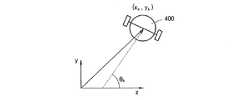
図24は、処理モデルを説明するための図面であって、基準座標系で移動体400の座標(xk,yk)を表す。ここで、媒介物処理モデル、すなわち、移動体の位置モデルは、次の数式(16)のように表現され、ランドマーク処理モデル、すなわち、地図のモデルは、次の数式(17)のように表現されうる。FIG. 24 is a diagram for explaining the processing model, and represents the coordinates (xk , yk ) of the moving
(xk,yk,θk)は、基準座標系上で以前上部映像を獲得する時の移動体の位置及び角度を表し、
(xk+1,yk+1,θk+1)は、基準座標系上で現在上部映像を獲得する時の移動体の位置及び角度を表し、
vは、移動体の線速度を表し、wは、移動体の角速度を表し、Tは、サンプリング時間を表す。
(Xk , yk , θk ) represents the position and angle of the moving body when the upper image is acquired on the reference coordinate system before,
(Xk + 1 , yk + 1 , θk + 1 ) represents the position and angle of the moving body when the current upper image is acquired on the reference coordinate system,
v represents the linear velocity of the moving object, w represents the angular velocity of the moving object, and T represents the sampling time.
図25に示すように、映像座標系上で中心点(xv,yv,zv)から点402までの距離dvは、次の数式(18)のように表現され、映像座標系上でxv軸及び点402までのベクトルがなす角度ψvは、次の数式(19)のように表現されうる。As shown in FIG. 25, the distance dv from the center point (xv , yv , zv ) to the
一方、前記の本発明の実施形態は、コンピュータで実行されうるプログラムで作成可能であり、コンピュータで読み取り可能な記録媒体を利用して前記プログラムを動作させる汎用ディジタルコンピューターで具現されうる。前記コンピュータで読み取り可能な記録媒体は、マグネチック保存媒体(例えば、ROM(Read Only Memory)、フレキシブルディスク、ハードディスク等)、光学的な読み取り媒体(例えば、CD−ROM、DVD(Digital Versatile Display)等)及びキャリアウェーブ(例えば、インターネットを介した伝送)のような保存媒体を含む。 On the other hand, the embodiment of the present invention can be created by a program that can be executed by a computer, and can be embodied by a general-purpose digital computer that operates the program using a computer-readable recording medium. The computer-readable recording medium includes a magnetic storage medium (for example, ROM (Read Only Memory), flexible disk, hard disk, etc.), an optical reading medium (for example, CD-ROM, DVD (Digital Versatile Display), etc. ) And carrier wave (eg, transmission over the Internet).
コンピュータで読み取り可能な記録媒体に保存されるコンピュータプログラムは、移動体の位置した周囲の上部を撮影して獲得した上部映像でコーナーを表すコーナー点を観測させ、観測されたコーナー点からランドマークを生成させるステップ及びランドマークから移動体の位置を推定させて地図を生成させるステップを行う。
ランドマークを生成させるステップでは、現在上部映像でコーナーを表すコーナー点の座標及びコーナー点を互いに区分するLFDのうち、少なくとも一つを利用する。そして、コーナー点の座標及び/又はLFDを利用して、コーナー点のうち、以前上部映像でランドマークやランドマーク候補であったコーナー点を観測させて検出する。以前上部映像でランドマークでもなくランドマーク候補でもなかったコーナー点を、新たなランドマーク候補として登録させ、ランドマーク候補のうち、所定回数以上コーナー点として観測されたランドマーク候補をランドマークとして登録させる。この時、ランドマークを登録させるステップは、移動体の位置した環境の上部映像を獲得させるステップと、獲得された映像をバッファリングさせ、バッファリングされた結果を以前上部映像として決定するステップと、現在上部映像のコーナー点の座標及びLFDのうち、少なくとも一つを映像特徴情報として抽出させるステップと、以前上部映像でのランドマーク及びランドマーク候補を現在上部映像で予測させるステップと、予測ランドマーク及びランドマーク候補についての情報と映像特徴情報とを比較させ、比較された結果を利用して、コーナー点のうち、以前上部映像でランドマークやランドマーク候補であったコーナー点を観測させ、以前上部映像でランドマークでもなくランドマーク候補でもなかったコーナー点を新たなランドマーク候補として登録させるステップと、ランドマーク候補のうち、所定回数以上コーナー点として観測されたランドマーク候補をランドマークとして登録させるステップと、を行う。A computer program stored in a computer-readable recording medium causes a corner point representing a corner to be observed in an upper image obtained by photographing the upper part around the moving object, and a landmark is detected from the observed corner point. A step of generating and a step of generating a map by estimating the position of the moving body from the landmark are performed.
In the step of generating the landmark, at least one of the coordinates of the corner point representing the corner in the current upper image and the LFD that separates the corner point from each other is used. Then, using the coordinates of the corner points and / or LFD, the corner points that were previously landmarks or landmark candidates in the upper video are observed and detected among the corner points. Register a corner point that was neither a landmark nor a landmark candidate in the upper video previously as a new landmark candidate, and among the landmark candidates, register a landmark candidate that was observed as a corner point more than a predetermined number of times as a landmark Let At this time, the step of registering the landmark includes acquiring an upper image of the environment where the moving object is located, buffering the acquired image, and determining the buffered result as the previous upper image, Extracting at least one of the coordinates of the corner point and LFD of the current upper video as video feature information; predicting a landmark and landmark candidate in the previous upper video in the current upper video; In addition, the information about the landmark candidates and the video feature information are compared, and using the result of the comparison, the corner points that were previously landmarks or landmark candidates in the upper video are observed among the corner points. A corner point that is neither a landmark nor a landmark candidate A step of registering as Domaku candidate, among the landmark candidates, and step of registering the observed landmark candidates as the corner point more than a predetermined number of times as a landmark, is carried out.
映像を獲得させるステップは、移動体の位置した環境の上部映像を獲得させるステップ、及び獲得された上部映像の歪曲を補正させるステップを行う。映像を獲得させるステップは、歪曲が補正された結果を低域通過フィルタリングさせるステップをさらに行う。または、映像を獲得させるステップは、移動体の位置した周囲の上部映像を獲得させるステップ、及び獲得された上部映像を低域通過フィルタリングさせるステップを行う。映像特徴情報を抽出させるステップは、現在上部映像でコーナー点を検出させ、検出されたコーナー点の座標を求めさせるステップ、及び検出されたコーナー点の周辺の映像を分析させ、分析された結果を利用して、コーナー点別にLFDを求めさせるステップを行う。ランドマーク及びランドマーク候補の位置を現在上部映像で予測させるステップは、以前上部映像で登録されたランドマーク及びランドマーク候補の位置の3次元座標を、前記以前上部映像が入力された時の移動体の位置及び方位角を利用して、以前上部映像の映像座標系を基準に2次元に変換させるステップと、変換された2次元座標を有するランドマーク及びランドマーク候補のうち、以前上部映像に属するランドマーク及びランドマーク候補のみを選択させるステップ、及び現在上部映像と以前上部映像との間の変化量を、選択された結果について計算させ、計算された変化量を利用して、現在上部映像にあるランドマーク及びランドマーク候補を予測させるステップを行う。 The step of acquiring an image includes a step of acquiring an upper image of the environment where the moving object is located and a step of correcting distortion of the acquired upper image. The step of acquiring the image further includes a step of low-pass filtering the result of correcting the distortion. Alternatively, the step of acquiring an image includes a step of acquiring an upper image around the moving object and a step of low-pass filtering the acquired upper image. The step of extracting image feature information includes a step of detecting a corner point in the current upper image, obtaining coordinates of the detected corner point, and analyzing an image around the detected corner point, and analyzing the analyzed result. Utilizing this, the step of obtaining the LFD for each corner point is performed. The step of predicting the position of the landmark and the landmark candidate in the current upper image is a movement of the landmark and the landmark candidate position previously registered in the upper image when the previous upper image is input. Using the position and azimuth of the body, a step of converting the previous upper image into a two-dimensional reference with respect to the image coordinate system of the previous upper image, and among the landmarks and landmark candidates having the converted two-dimensional coordinates, The step of selecting only the landmarks and landmark candidates to which the image belongs and the amount of change between the current upper image and the previous upper image are calculated for the selected result, and the current upper image is calculated using the calculated change amount. The step of predicting the landmarks and landmark candidates at is performed.
コーナー点を観測して新たなランドマーク候補を登録させるステップは、コーナー点のそれぞれに対して、コーナー点と最も近い予測ランドマークやランドマーク候補を見つけさせるステップと、コーナー点のそれぞれに対して、コーナー点と検出されたランドマークやランドマーク候補との間の距離が第1所定距離以下であるか否かを判断させるステップと、検出されたランドマークやランドマーク候補との距離が第1所定距離以下のコーナー点のそれぞれに対して、コーナー点のLFDと検出されたランドマークやランドマーク候補のLFDとの間の距離が第2所定距離以下であるか否かを判断させるステップと、コーナー点のLFDと検出されたランドマークやランドマーク候補のLFDとの間の距離が第2所定距離以下であると判断されれば、コーナー点と最も近い位置にランドマークが存在するか、それともランドマーク候補が存在するかを判断させるステップと、ランドマークが存在すると判断されれば、ランドマークが観測された回数を表すランドマークフラグをアッパーカウンティングさせるステップと、ランドマーク候補が存在すると判断されれば、ランドマーク候補が観測された回数を表すランドマーク候補フラグをアッパーカウンティングさせるステップ、及び検出されたランドマークやランドマーク候補及び第1所定距離より遠く位置したコーナー点、または検出されたランドマークやランドマーク候補のLFD及び第2所定距離より遠く位置したLFDに該当するコーナー点を新たなランドマーク候補として決定し、決定された新たなランドマーク候補についての情報を登録させるステップを行う。 The step of observing a corner point and registering a new landmark candidate is for each corner point to find a predicted landmark or landmark candidate closest to the corner point, and for each corner point. Determining whether the distance between the corner point and the detected landmark or landmark candidate is equal to or less than a first predetermined distance, and the distance between the detected landmark or landmark candidate is the first Determining whether the distance between the corner point LFD and the detected landmark or landmark candidate LFD is less than or equal to a second predetermined distance for each corner point less than or equal to a predetermined distance; The distance between the corner point LFD and the detected landmark or landmark candidate LFD is determined to be less than or equal to the second predetermined distance. If it is determined that the landmark is present at the position closest to the corner point or whether there is a landmark candidate, and if it is determined that the landmark exists, the number of times the landmark is observed is represented. A step of counting the landmark flag in the upper direction, and a step of counting the landmark candidate flag indicating the number of times the landmark candidate is observed if it is determined that the landmark candidate exists, and the detected landmark or landmark A corner point corresponding to the candidate and the corner point located farther than the first predetermined distance, or the detected landmark and the LFD of the landmark candidate and the LFD located farther than the second predetermined distance are determined as new landmark candidates, New landmark candidates decided Performing the step of registering the information about.
ランドマークを登録するステップは、登録されたランドマーク候補のうち、互いに重複しているランドマーク候補を除去させ、重複していないランドマーク候補の2次元映像座標から3次元映像座標を推定させるステップをさらに行う。映像座標を推定させるステップは、登録されたランドマーク候補のそれぞれに対して、最も近いランドマーク候補間の最小距離を求めさせるステップと、最小距離が第3所定距離以下であるか否かを判断させるステップと、第3所定距離以下の最小距離を有するランドマーク候補は互いに重複していると決定し、重複しているランドマーク候補を除去させるステップ、及び第3所定距離より遠く離れた最小距離を有するランドマーク候補は互いに重複していないと決定し、重複していないランドマーク候補の3次元映像座標を推定させるステップを行う。 The step of registering the landmark is a step of removing the overlapping landmark candidates from the registered landmark candidates and estimating the three-dimensional video coordinates from the two-dimensional video coordinates of the non-overlapping landmark candidates. Do further. The step of estimating the video coordinates includes determining a minimum distance between the nearest landmark candidates for each of the registered landmark candidates, and determining whether the minimum distance is equal to or less than a third predetermined distance. Determining that the landmark candidates having the minimum distance equal to or smaller than the third predetermined distance overlap each other, removing the overlapping landmark candidates, and the minimum distance farther than the third predetermined distance. It is determined that the landmark candidates having no overlap with each other, and a step of estimating the three-dimensional video coordinates of the landmark candidates that do not overlap is performed.
以下、移動体としてロボットを採択しつつ、本発明による上部映像を利用した移動体の位置推定及び地図の生成装置と方法、並びにその装置を制御するコンピュータプログラムを保存するコンピュータで読み取り可能な記録媒体により、ロボットの自身の位置及び方位角をテストした結果を、添付された図面を参照して次の通りに説明する。
まず、ロボットの各位置での距離誤差の和を総サンプル数で除算した結果を距離平均誤差として定義し、ロボットの各位置での方位角度の誤差の和を総サンプル数で除算した結果を方位角の平均誤差として定義する。このような誤差を計算するために、まず、ロボットが学習を始めた初期位置を基準座標系の原点に設定し、その初期位置でのロボットの進行方向を基準座標系のx軸方向と一致させる。この時、ロボットの実際の位置及び方位角を(xd,yd,θd)として表記し、ロボットの測定位置及び方位角を(x,y,θ)として表記する場合、距離誤差edは、次の数式(20)のように表現され、cmの単位を有し、方位角誤差eθは、次の数式(21)のように表現され、degreeの単位を有しうる。Hereinafter, a moving body position estimation and map generation apparatus and method using the upper image according to the present invention, and a computer-readable recording medium storing a computer program for controlling the apparatus while adopting a robot as the moving body The results of testing the robot's own position and azimuth are described as follows with reference to the attached drawings.
First, the result of dividing the sum of the distance errors at each position of the robot by the total number of samples is defined as the distance average error, and the result of dividing the sum of the errors of the azimuth angles at each position of the robot by the total number of samples is It is defined as the mean error of the corner. In order to calculate such an error, first, the initial position where the robot has started learning is set as the origin of the reference coordinate system, and the traveling direction of the robot at the initial position is matched with the x-axis direction of the reference coordinate system. . At this time, when the actual position and azimuth angle of the robot are expressed as (xd , yd , θd ) and the measurement position and azimuth angle of the robot are expressed as (x, y, θ), the distance errored Is expressed as in the following equation (20) and has a unit of cm, and the azimuth error eθ is expressed as in the following equation (21) and may have a unit of degree.
図26は、テストするロボットの外観を示す写真であって、輪駆動部550、ロボット551、上部カメラ552及び天井554を示す。ここで、図3に示す映像特徴情報抽出部36は、天井554で複数のコーナー点560ないし578を検出できる。
図26に示す輪駆動部550は、図1に示す走行処理部14の役割を行い、上部カメラ552は、図3に示す映像獲得部30に内蔵されうる。FIG. 26 is a photograph showing the appearance of the robot to be tested, and shows the
A
図27A及び図27Bは、ロボットが移動する経路を例示的に示す図面であって、図27Aは、ロボットが走行するアパートの居間をはじめとして、アパートの平面図を示し、図27Bは、ロボットが走行する経路を例示的に示す図面である。各矢印に対応する数字は、実際mm単位で表示された距離値を意味する。図27Bに示す経路は、基準座標系で表示される。 FIGS. 27A and 27B are diagrams illustrating an example of a route along which the robot moves. FIG. 27A shows a plan view of the apartment including the living room of the apartment where the robot runs, and FIG. It is drawing which shows the path | route which drive | works. The number corresponding to each arrow actually means the distance value displayed in mm. The route shown in FIG. 27B is displayed in the reference coordinate system.
図27Aに示すアパートの居間で、ロボットは、図27Bに示す矢印方向の経路によって地図を自動的に学習する。この時、ロボットを図27Bに示す学習開始点(0,0)600で学習を開始させる。この時、図27Bに示す各ポイントで、基準座標系でロボットの座標値を実測により求め、学習が終わった後、それらのポイントで位置及び方位角の誤差を測定する。 In the living room of the apartment shown in FIG. 27A, the robot automatically learns the map by the route in the arrow direction shown in FIG. 27B. At this time, the robot starts learning at a learning start point (0, 0) 600 shown in FIG. 27B. At this time, at each point shown in FIG. 27B, the coordinate value of the robot is obtained by actual measurement in the reference coordinate system, and after learning is completed, the error in position and azimuth is measured at those points.
一方、定規と分度器とを使用して、ロボットの位置及び方位角を測定し、位置及び方位角を測定する順序は、次の通りである。
図28は、ロボットの外観を示す図面であり、図29Aないし図29Dは、ロボットの位置測定を示す写真である。
まず、ロボットをテストポイント、例えば、図27Bに示すポイント602ないし622のうち、何れか1箇所のポイントに位置させた後、ロボットの輪軸634と左右輪の外側面630及び632とが出合う点を地面方向に投影した時、地面と出合う点を図29A及び図29Bに示すように印を付ける。この時、ロボットを移動させた後、図29Cに示すように、地面に印を付けられた二つのマークを連結する線分を描いた後、線分の中心点と原点との距離をロボットの距離として測定する。さらに、図29Dに示すように、線分が地面の基準線となす角度をロボットの角度として設定する。On the other hand, the position and azimuth angle of the robot are measured using a ruler and a protractor, and the order of measuring the position and azimuth angle is as follows.
FIG. 28 is a view showing the appearance of the robot, and FIGS. 29A to 29D are photographs showing the position measurement of the robot.
First, after positioning the robot at a test point, for example, any one of the
図30は、前記の測定方法を利用して、15個のポイントのそれぞれに対して3回測定して、45個のサンプルデータを獲得する場合、測定データの一例を示す図面である。
図31は、図30から得られた距離誤差に対するMinitabというデータ分析プログラムを利用して実施した、統計的分析結果を説明するための図面であって、最大許容距離誤差(USL、Upper Specification Limit)が10cmである場合、測定された距離誤差についての統計分析結果を表すグラフであって、縦軸は、確率分布を表し、横軸は、距離誤差の範囲を表す。FIG. 30 is a diagram illustrating an example of measurement data when 45 sample data are obtained by measuring three times for each of 15 points using the measurement method.
FIG. 31 is a diagram for explaining a statistical analysis result performed using a data analysis program called Minitab for the distance error obtained from FIG. 30, and is a maximum allowable distance error (USL, Upper Specification Limit). Is a graph representing a statistical analysis result of the measured distance error, where the vertical axis represents the probability distribution and the horizontal axis represents the range of the distance error.
図31からUSLが10cmである場合、30個の観測データ数に対して平均距離誤差は5.9018cmであり、この時、分散程度を測定するシグマレベルは、全体工程能力に対してZ.Bench+1.5の数式で2.74シグマレベルであるということが分かる。シグマレベルは、本来、不良率を表す指標であって、6シグマレベルは、100万個の生産時、3.4個の不良が発生するレベルを意味する。このシックスシグマとは,設計製造やサービス提供に関連するビジネス・プロセス上の欠陥を最小化することにより、業務パフォーマンスを改善するための経営・品質管理手法である.
図32は、方位角の誤差に対してMinitabというデータ分析プログラムを利用して実施した統計的な分析結果を説明するための図面であって、最大方位角の許容誤差が5度である場合、測定された方位角誤差についての統計分析結果を表すグラフであって、縦軸は、観測された方位角データの確率分布を表し、横軸は、方位角誤差の範囲を表す。From FIG. 31, when USL is 10 cm, the average distance error is 5.9018 cm for the number of observation data of 30, and at this time, the sigma level for measuring the degree of dispersion is Z. It can be seen from the formula of Bench +1.5 that it is 2.74 sigma level. The sigma level is originally an index representing the defect rate, and the 6 sigma level means a level at which 3.4 defects occur when one million units are produced. Six Sigma is a management and quality control technique for improving business performance by minimizing business process defects related to design manufacturing and service provision.
FIG. 32 is a diagram for explaining a statistical analysis result performed using a data analysis program called Minitab with respect to an azimuth angle error, where the maximum azimuth angle tolerance is 5 degrees. It is a graph showing the statistical analysis result about the measured azimuth angle error, Comprising: A vertical axis | shaft represents the probability distribution of the observed azimuth angle data, and a horizontal axis represents the range of the azimuth angle error.
図32からUSLが5度である場合、30個の観測データ数に対して平均距離誤差は1.94333度であり、この時、分散程度を測定するシグマレベルは、全体の工程能力に対してZ.Bench+1.5の数式で3.43シグマレベルであるということが分かる。ここで、シグマは誤差に対する偏差が良好であることを示すものであり、前記の結果から本発明の方法が極めてロバスト(robust)であることを統計的に示している。 From FIG. 32, when USL is 5 degrees, the average distance error is 1.94333 degrees with respect to the number of 30 observation data. At this time, the sigma level for measuring the degree of dispersion is Z. It can be seen that it is 3.43 sigma level in the formula of Bench + 1.5. Here, sigma indicates that the deviation with respect to the error is good, and the above results indicate statistically that the method of the present invention is extremely robust.
以上のように、本発明では、コーナー点や映像特徴周辺記述子を用いてランドマークを生成するため、上部映像そのものを保存したり上部映像そのものを用いて演算することなくランドマークを生成することができ、演算量を大幅に減らすことができる。演算量が減少するため、生成したランドマークからの位置の推定及び地図の作成をともに行うことが可能となる。 As described above, in the present invention, since the landmark is generated by using the corner point and the video feature peripheral descriptor, the landmark can be generated without saving the upper video itself or performing the calculation using the upper video itself. And the amount of calculation can be greatly reduced. Since the amount of calculation decreases, it is possible to both estimate the position from the generated landmark and create a map.
また、カメラなどを用いて上部映像を取得することでランドマークを生成するため、レーザーレンジファインダーのような高価なカメラが不要である。このとき、上部映像を取得するために、安価の一台のカメラのみを利用すれば良いため、製造コストを低減させることができる。
また、上述の通り、ランドマークは、上部映像に基づいて自動的に生成される。よって、例えば、赤外線ランドマーク、色パターンのような人工ランドマークなどの別途の付着物によりランドマークを生成する必要がない。このような別途の付着物によるランドマークを用いた場合には、これらのランドマークをセンシングする際に、照明などの影響を受けてランドマークを正確に取得することが出来ない場合がある。しかし、本発明のように、上部映像に基づいてランドマークを生成する場合には、前述のような照明の影響を受けることが無く正確にランドマークを生成でき、正確な位置の推定及び正確な地図作製を行うことができる。Further, since the landmark is generated by acquiring the upper image using a camera or the like, an expensive camera such as a laser range finder is unnecessary. At this time, since it is sufficient to use only one inexpensive camera in order to acquire the upper image, the manufacturing cost can be reduced.
Further, as described above, the landmark is automatically generated based on the upper video. Therefore, for example, it is not necessary to generate the landmarks by separate deposits such as infrared landmarks and artificial landmarks such as color patterns. In the case where landmarks due to such extraneous matter are used, there are cases where the landmarks cannot be obtained accurately due to the influence of lighting or the like when sensing these landmarks. However, when the landmark is generated based on the upper image as in the present invention, the landmark can be generated accurately without being affected by the illumination as described above, and the accurate position estimation and accurate You can make a map.
ランドマークの候補を新たに登録する時、コーナー点の特徴を表すSIFT(Scale Invariant Feature Transform)記述子のような映像特徴周辺記述子を利用する場合には、移動体の位置した室内環境の全体の照度が変化するとしても、映像の輝度変化は一定である。よって、移動体の位置した照明の変化にロバスト性を有するランドマークを見つけて登録できる。これにより移動体の位置認識及び地図作成を正確に行わせることができる。例えば、移動体の平均距離誤差を約6cm以内に維持し、方位角の平均誤差を約2度以内に維持できる。ここで、ロバスト性とは,外乱や設計誤差などの不確定な変動に対して,システム特性が現状を維持できることを意味する。 When a landmark candidate is newly registered, when an image feature peripheral descriptor such as a SIFT (Scale Invariant Feature Transform) descriptor representing the feature of a corner point is used, the entire indoor environment where the moving object is located is used. Even if the illuminance changes, the luminance change of the image is constant. Therefore, landmarks that are robust to changes in illumination where the moving body is located can be found and registered. Thereby, the position recognition and map creation of a moving body can be performed correctly. For example, the average distance error of the moving body can be maintained within about 6 cm, and the average azimuth angle error can be maintained within about 2 degrees. Here, robustness means that the current system characteristics can be maintained against uncertain fluctuations such as disturbances and design errors.
さらに、オプティカルフロートラックキングと映像特徴周辺記述子とを何れも利用する場合には、従来のSLAM技法の問題であるデータ関連問題、すなわち、Large closed loop問題を解決でき、EKF基盤のSLAM(Simultaneous Location And Map Building)技法の安定性を確保できる。 Furthermore, when both the optical flow tracking and the video feature peripheral descriptor are used, the data-related problem that is the problem of the conventional SLAM technique, that is, the large closed loop problem, can be solved, and the EKF-based SLAM (Simultaneous) is solved. The stability of the Location And Map Building) technique can be ensured.
本発明は、ロボットに関連した技術分野に好適に適用され得る。 The present invention can be suitably applied to a technical field related to a robot.
30 映像獲得部
32 映像バッファ
34 ランドマーク及びランドマーク候補予測部
36 映像特徴情報抽出部
38 観測及び登録部
40 ランドマーク候補処理部
42 ランドマーク登録部
IN1 入力端子
OUT2、OUT3 出力端子
30
Claims (30)
Translated fromJapanese前記ランドマークから前記移動体の位置を推定し、かつ地図を生成する位置及び地図演算部と、を備えることを特徴とする上部映像を利用した移動体の位置推定及び地図の生成装置。A landmark generator that observes a corner point that represents a corner in the upper image acquired by photographing the upper part of the environment where the moving object is located, and generates a landmark from the observed corner point;
An apparatus for estimating a position of a moving object and generating a map using an upper image, comprising: a position for estimating the position of the moving object from the landmark and generating a map; and a map calculation unit.
現在上部映像で、前記コーナー点の座標及び前記コーナー点を互いに区分する映像特徴周辺記述子のうち、少なくとも一つを利用して観測した前記コーナー点のうち、以前上部映像でランドマークやランドマーク候補であったコーナー点を見つけ、以前上部映像でランドマークでもなくランドマーク候補でもなかった前記コーナー点を新たなランドマーク候補として登録し、前記ランドマーク候補のうち、所定回数以上前記コーナー点として観測されたランドマーク候補をランドマークとして登録し、
前記現在上部映像は、現在獲得された前記上部映像に該当し、前記以前上部映像とは、以前に獲得された前記上部映像に該当することを特徴とする請求項1に記載の上部映像を利用した移動体の位置推定及び地図の生成装置。The landmark generation unit
Among the corner points observed using at least one of the coordinates of the corner points and the image feature peripheral descriptors that distinguish the corner points from each other in the current upper image, a landmark or a landmark in the previous upper image Find a corner point that was a candidate, and register the corner point that was not a landmark or a landmark candidate in the upper video as a new landmark candidate. Register the observed landmark candidates as landmarks,
The upper image according to claim 1, wherein the current upper image corresponds to the currently acquired upper image, and the previous upper image corresponds to the previously acquired upper image. Position estimation and map generation device.
前記移動体の走行を制御し、前記走行についての情報を出力する走行処理部をさらに備え、
前記位置及び地図演算部は、前記走行処理部から入力した前記走行についての情報と、前記ランドマーク生成部から入力した前記ランドマークとから移動体の位置を推定し、かつ地図を生成し、前記ランドマークについての情報を前記ランドマーク生成部に出力することを特徴とする請求項2に記載の上部映像を利用した移動体の位置推定及び地図の生成装置。A mobile object position estimation and map generation device using the upper image,
A travel processing unit for controlling travel of the mobile body and outputting information about the travel;
The position and map calculation unit estimates the position of the moving object from the information about the travel input from the travel processing unit and the landmark input from the landmark generation unit, and generates a map, The apparatus for estimating a position of a moving object and generating a map using the upper image according to claim 2, wherein information on the landmark is output to the landmark generation unit.
前記移動体の位置した環境の上部映像を獲得する映像獲得部と、
前記映像獲得部から入力した前記獲得された映像をバッファリングし、バッファリングされた結果を前記以前上部映像として出力する映像バッファと、
前記映像獲得部で現在獲得された前記現在上部映像のコーナー点の座標及び前記映像特徴周辺記述子のうち、少なくとも一つを映像特徴情報として抽出する映像特徴情報抽出部と、
前記以前上部映像での前記ランドマーク及び前記ランドマーク候補を、前記現在上部映像で予測するランドマーク及びランドマーク候補予測部と、
前記予測ランドマーク及びランドマーク候補についての情報と前記映像特徴情報とを比較し、比較された結果により前記コーナー点のうち、以前上部映像でランドマークやランドマーク候補であったコーナー点を観測して見つけ、前記以前上部映像で前記ランドマークでもなく、前記ランドマーク候補でもなかった前記コーナー点を新たなランドマーク候補として登録する観測及び登録部と、
前記ランドマーク候補のうち、所定回数以上前記コーナー点として観測されたランドマーク候補を、前記ランドマークとして登録するランドマーク登録部と、を備えることを特徴とする請求項2に記載の上部映像を利用した移動体の位置推定及び地図の生成装置。The landmark generation unit
An image acquisition unit for acquiring an upper image of the environment in which the moving object is located;
A buffer for buffering the acquired video input from the video acquisition unit, and outputting a buffered result as the previous upper video;
A video feature information extraction unit that extracts at least one of the coordinates of the corner point of the current upper video currently acquired by the video acquisition unit and the video feature peripheral descriptor as video feature information;
The landmark and landmark candidate prediction unit for predicting the landmark and landmark candidate in the previous upper image, and the current upper image;
The information about the predicted landmarks and landmark candidates is compared with the video feature information, and the corner points that were previously landmarks or landmark candidates in the upper video are observed based on the comparison result. An observation and registration unit that registers the corner point that was not the landmark nor the landmark candidate in the previous upper image as a new landmark candidate;
The top image according to claim 2, further comprising: a landmark registration unit that registers, as the landmark, a landmark candidate that is observed as the corner point a predetermined number of times or more among the landmark candidates. A device for estimating the position of a moving object and generating a map.
前記移動体の位置した環境の前記上部映像を獲得する上部映像獲得部と、
前記獲得された上部映像の歪曲を補正する歪曲補正部と、を備えることを特徴とする請求項4に記載の上部映像を利用した移動体の位置推定及び地図の生成装置。The video acquisition unit
An upper image acquisition unit for acquiring the upper image of the environment in which the moving object is located;
The apparatus according to claim 4, further comprising: a distortion correction unit configured to correct distortion of the acquired upper image.
前記移動体の位置した環境の前記上部映像を獲得する上部映像獲得部と、
前記獲得された上部映像を低域通過フィルタリングする低域通過フィルタと、を備えることを特徴とする請求項4に記載の上部映像を利用した移動体の位置推定及び地図の生成装置。The video acquisition unit
An upper image acquisition unit for acquiring the upper image of the environment in which the moving object is located;
The apparatus of claim 4, further comprising: a low-pass filter that performs low-pass filtering on the acquired upper image.
前記歪曲が補正された結果を低域通過フィルタリングする低域通過フィルタをさらに備えることを特徴とする請求項5に記載の上部映像を利用した移動体の位置推定及び地図の生成装置。The video acquisition unit
The apparatus of claim 5, further comprising a low-pass filter that performs low-pass filtering on a result of correcting the distortion.
前記獲得された上部映像で関心領域を設定し、設定された関心領域のみに対して前記歪曲を補正することを特徴とする請求項5に記載の上部映像を利用した移動体の位置推定及び地図の生成装置。The distortion correction unit
6. The position estimation and map of a moving body using the upper image according to claim 5, wherein a region of interest is set in the acquired upper image, and the distortion is corrected only for the set region of interest. Generator.
前記現在上部映像で前記コーナー点を検出し、前記検出されたコーナー点の座標を出力するコーナー点検出部と、
前記検出されたコーナー点の周辺の映像を分析し、前記分析された結果から前記コーナー点別に前記映像特徴周辺記述子を演算する記述子演算部と、を備えることを特徴とする請求項4に記載の上部映像を利用した移動体の位置推定及び地図の生成装置。The video feature information extraction unit includes:
A corner point detection unit for detecting the corner point in the current upper image and outputting coordinates of the detected corner point;
5. A descriptor calculating unit that analyzes a video around the detected corner point and calculates the video feature peripheral descriptor for each corner point from the analyzed result. An apparatus for estimating a position of a moving object and generating a map using the upper image described above.
前記以前上部映像で登録された前記ランドマーク及び前記ランドマーク候補の位置の3次元座標を、前記以前上部映像が入力された時の前記移動体の位置及び方位角を利用して、前記以前上部映像の映像座標系を基準に2次元に変換する映像座標変換部と、
前記映像座標変換部から入力した変換された2次元座標を有する前記ランドマーク及び前記ランドマーク候補のうち、前記以前上部映像に属する前記ランドマーク及び前記ランドマーク候補のみを選択する選択部と、
前記映像獲得部から入力した前記現在上部映像と、前記映像バッファから入力した前記以前上部映像との間の変化量を、前記選択された結果について計算し、前記計算された変化量を利用して、前記現在上部映像にある前記ランドマーク及び前記ランドマーク候補を予測する位置予測部と、を備えることを特徴とする請求項4に記載の上部映像を利用した移動体の位置推定及び地図の生成装置。The landmark and landmark candidate prediction unit are:
Using the position and azimuth of the moving body when the previous upper image is input, the three-dimensional coordinates of the landmark and the landmark candidate position registered in the previous upper image are used. An image coordinate conversion unit that converts the image coordinate system into a two-dimensional image based on the image coordinate system;
A selection unit for selecting only the landmark and the landmark candidate belonging to the previous upper image among the landmark and the landmark candidate having the converted two-dimensional coordinates input from the video coordinate conversion unit;
A change amount between the current upper image input from the image acquisition unit and the previous upper image input from the image buffer is calculated for the selected result, and the calculated change amount is used. 5. The position estimation unit for predicting the landmark and the landmark candidate in the current upper image, and generating a map and generating a map using the upper image according to claim 4. apparatus.
オプティカルフロートラッカーを利用して、前記現在上部映像にある前記ランドマーク及び前記ランドマーク候補の位置を予測することを特徴とする請求項13に記載の上部映像を利用した移動体の位置推定及び地図の生成装置。The position prediction unit
14. The position estimation and map of a moving body using the upper image according to claim 13, wherein the position of the landmark and the landmark candidate in the current upper image is predicted using an optical flow tracker. Generator.
前記コーナー点のそれぞれに対して、前記コーナー点と最も近い予測ランドマークやランドマーク候補を探すランドマーク及びランドマーク候補検索部と、
前記コーナー点のそれぞれに対して、前記コーナー点と前記検出されたランドマークやランドマーク候補との間の距離を計算する第1距離計算部と、
前記第1距離計算部で計算された距離と第1所定距離とを比較する第1比較部と、
前記第1比較部で比較された結果に応答して、前記コーナー点の映像特徴周辺記述子と、前記検出されたランドマークやランドマーク候補の映像特徴周辺記述子との間の距離を計算する第2距離計算部と、
前記第2距離計算部で計算された距離と第2所定距離とを比較する第2比較部と、
前記第2比較部で比較された結果に応答して、前記コーナー点と最も近い位置に前記ランドマークが存在するか、それとも前記ランドマーク候補が存在するかを識別するランドマーク及びランドマーク候補識別部と、
前記識別された結果に応答して、前記ランドマークが観測された回数を表すランドマークフラグをアッパーカウンティングするか、前記ランドマーク候補が観測された回数を表すランドマーク候補フラグをアッパーカウンティングするカウンターと、
前記第1比較部及び前記第2比較部で比較された結果に応答して、前記コーナー点のうち、前記以前上部映像で前記ランドマークでもなく、前記ランドマーク候補でもなかったコーナー点を、前記新たなランドマーク候補として見つけ、検出された前記新たなランドマーク候補についての情報を登録するランドマーク候補初期化部と、を備えることを特徴とする請求項4に記載の上部映像を利用した移動体の位置推定及び地図の生成装置。The observation and registration unit
For each of the corner points, a landmark and landmark candidate search unit for searching for a predicted landmark or landmark candidate closest to the corner point;
A first distance calculation unit that calculates a distance between the corner point and the detected landmark or landmark candidate for each of the corner points;
A first comparison unit that compares the distance calculated by the first distance calculation unit with a first predetermined distance;
In response to the result of comparison by the first comparison unit, the distance between the video feature peripheral descriptor of the corner point and the video feature peripheral descriptor of the detected landmark or landmark candidate is calculated. A second distance calculator;
A second comparison unit that compares the distance calculated by the second distance calculation unit with a second predetermined distance;
Landmark and landmark candidate identification for identifying whether the landmark is present at a position closest to the corner point or the landmark candidate in response to a result of comparison by the second comparison unit And
In response to the identified result, a counter that counts a landmark flag that represents the number of times that the landmark has been observed, or a counter that counts the landmark candidate flag that represents the number of times that the landmark candidate has been observed, and ,
In response to the result of the comparison performed by the first comparison unit and the second comparison unit, the corner point that is not the landmark or the landmark candidate in the previous upper image is the corner point. 5. The movement using the upper image according to claim 4, further comprising: a landmark candidate initialization unit that finds a new landmark candidate and registers information about the detected new landmark candidate. Body position estimation and map generation device.
前記登録されたランドマーク候補のうち、互いに重複しているランドマーク候補を除去し、重複していないランドマーク候補等の2次元映像座標から3次元映像座標を推定するランドマーク候補処理部をさらに備え、
前記ランドマーク登録部は、前記重複していないランドマーク候補のうち、前記所定回数以上前記コーナー点として観測されたランドマーク候補を前記ランドマークとして登録することを特徴とする請求項4に記載の上部映像を利用した移動体の位置推定及び地図の生成装置。The landmark generation unit
A landmark candidate processing unit that removes overlapping landmark candidates from the registered landmark candidates and estimates a three-dimensional video coordinate from a two-dimensional video coordinate such as a non-overlapping landmark candidate; Prepared,
5. The landmark registration unit according to claim 4, wherein the landmark registration unit registers, as the landmark, a landmark candidate observed as the corner point more than the predetermined number of times among the non-overlapping landmark candidates. An apparatus for estimating the position of a moving object and generating a map using the upper image.
前記登録されたランドマーク候補のそれぞれに対して、最も近いランドマーク候補間の最小距離を計算する第3距離計算部と、
前記各最小距離と第3所定距離とを比較する第3比較部と、
前記第3比較部で比較された結果に応答して、前記各ランドマーク候補が重複しているか否かを決定し、決定された結果に相応して、重複しているランドマーク候補を除去するランドマーク候補除去部と、
前記第3比較部で比較された結果に応答して、前記重複していないランドマーク候補の3次元映像座標を推定する座標推定部と、を備えることを特徴とする請求項16に記載の上部映像を利用した移動体の位置推定及び地図の生成装置。The landmark candidate processing unit
A third distance calculating unit that calculates a minimum distance between nearest landmark candidates for each of the registered landmark candidates;
A third comparison unit for comparing each of the minimum distances with a third predetermined distance;
In response to the result of comparison by the third comparison unit, it is determined whether or not each of the landmark candidates is duplicated, and according to the decided result, the duplicate landmark candidate is removed. A landmark candidate removal unit;
The upper part according to claim 16, further comprising: a coordinate estimation unit that estimates a three-dimensional image coordinate of the non-overlapping landmark candidate in response to a result of comparison by the third comparison unit. A mobile object position estimation and map generation device using video.
(b)前記ランドマークから前記移動体の位置を推定し、かつ地図を生成するステップと、を含むことを特徴とする移動体の位置推定及び地図生成方法。(A) observing a corner point representing a corner in the upper image acquired by photographing the upper part of the environment where the moving object is located, and generating a landmark from the observed corner point;
(B) Estimating the position of the moving object from the landmark and generating a map; and a method for estimating the position of the moving object and generating a map.
現在上部映像で前記コーナー点の座標及び前記コーナー点を互い区分させる映像特徴周辺記述子のうち、少なくとも一つを利用して、前記コーナー点のうち、以前上部映像でランドマークやランドマーク候補であったコーナー点を観測し、以前上部映像でランドマークでもなくランドマーク候補でもなかった前記コーナー点を新たなランドマーク候補として登録し、前記ランドマーク候補のうち、所定回数以上前記コーナー点として観測されたランドマーク候補をランドマークとして登録し、
前記現在上部映像は、現在獲得された前記上部映像に該当し、前記以前上部映像は、以前に獲得された前記上部映像に該当することを特徴とする請求項19に記載の上部映像を利用した移動体の位置推定及び地図生成方法。The step (a) includes:
At least one of the coordinates of the corner point in the current upper image and the image feature peripheral descriptor that separates the corner points from each other is used, and the landmark or landmark candidate in the previous upper image of the corner point is used. Observe the corner point, and register the corner point that was neither a landmark nor a landmark candidate in the upper video as a new landmark candidate, and observe it as the corner point more than a predetermined number of times among the landmark candidates Registered landmark candidates as landmarks,
The upper image according to claim 19, wherein the current upper image corresponds to the currently acquired upper image, and the previous upper image corresponds to the previously acquired upper image. A method for estimating the position of a moving object and generating a map.
前記移動体の位置した環境の上部映像を獲得するステップと、
前記獲得された映像をバッファリングし、バッファリングされた結果を前記以前上部映像として決定するステップと、
前記現在上部映像のコーナー点の座標及び前記映像特徴周辺記述子のうち、少なくとも一つを映像特徴情報として抽出するステップと、
前記以前上部映像での前記ランドマーク及び前記ランドマーク候補を前記現在上部映像で予測するステップと、
前記予測ランドマーク及びランドマーク候補についての情報と前記映像特徴情報とを比較し、比較された結果を利用して、前記コーナー点のうち、以前上部映像でランドマークやランドマーク候補であったコーナー点を観測して見つけ、前記以前上部映像で前記ランドマークでもなく、前記ランドマーク候補でもなかった前記コーナー点を新たなランドマーク候補として登録するステップと、
前記ランドマーク候補のうち、所定回数以上前記コーナー点として観測されたランドマーク候補を前記ランドマークとして登録するステップと、を含むことを特徴とする請求項20に記載の上部映像を利用した移動体の位置推定及び地図生成方法。The step (a) includes:
Obtaining an upper image of the environment in which the moving object is located;
Buffering the acquired video and determining the buffered result as the previous top video;
Extracting at least one of the coordinates of the corner point of the current upper video and the video feature peripheral descriptor as video feature information;
Predicting the landmarks and landmark candidates in the previous upper video in the current upper video;
The information about the predicted landmark and the landmark candidate is compared with the video feature information, and using the result of the comparison, among the corner points, the corner that was the landmark or landmark candidate in the upper video before. Observing and finding a point, and registering the corner point that was not the landmark nor the landmark candidate in the previous upper image as a new landmark candidate;
The mobile object using the upper image according to claim 20, further comprising: registering, as the landmark, a landmark candidate observed as the corner point a predetermined number of times or more among the landmark candidates. Location estimation and map generation method.
前記移動体の位置した環境の前記上部映像を獲得するステップと、
前記獲得された上部映像の歪曲を補正するステップと、を含むことを特徴とする請求項21に記載の上部映像を利用した移動体の位置推定及び地図生成方法。The step of acquiring the video includes
Obtaining the upper image of the environment in which the moving object is located;
The method according to claim 21, further comprising: correcting distortion of the acquired upper image.
前記移動体の位置した環境の前記上部映像を獲得するステップと、
前記獲得された上部映像を低域通過フィルタリングするステップと、を含むことを特徴とする請求項21に記載の上部映像を利用した移動体の位置推定及び地図生成方法。The step of acquiring the video includes
Obtaining the upper image of the environment in which the moving object is located;
The method of claim 21, further comprising: low-pass filtering the acquired upper image.
前記歪曲が補正された結果を低域通過フィルタリングするステップをさらに含むことを特徴とする請求項22に記載の上部映像を利用した移動体の位置推定及び地図生成方法。The step of acquiring the video includes
The method according to claim 22, further comprising low-pass filtering a result of correcting the distortion.
前記現在上部映像で前記コーナー点を検出し、前記検出されたコーナー点の座標を求めるステップと、
前記検出されたコーナー点の周辺に映像を分析し、前記分析された結果を利用して、前記コーナー点別に前記映像特徴周辺記述子を求めるステップと、を含むことを特徴とする請求項21に記載の上部映像を利用した移動体の位置推定及び地図生成方法。The step of extracting the video feature information includes:
Detecting the corner point in the current upper image and determining the coordinates of the detected corner point;
The method of claim 21, further comprising: analyzing a video around the detected corner point, and determining the video feature peripheral descriptor for each corner point using the analyzed result. A method for estimating a position of a moving object and generating a map using the above-described upper image.
前記以前上部映像で登録された前記ランドマーク及び前記ランドマーク候補の位置の3次元座標を、前記以前上部映像が入力された時の前記移動体の位置及び方位角を利用して、前記以前上部映像の映像座標系を基準に2次元に変換するステップと、
前記変換された2次元座標を有する前記ランドマーク及び前記ランドマーク候補のうち、前記以前上部映像に属する前記ランドマーク及び前記ランドマーク候補のみを選択するステップと、
前記現在上部映像と前記以前上部映像との間の変化量を、前記選択された結果について計算し、前記計算された変化量を利用して、前記現在上部映像にある前記ランドマーク及び前記ランドマーク候補を予測するステップと、を含むことを特徴とする請求項21に記載の上部映像を利用した移動体の位置推定及び地図生成方法。Predicting the position of the landmark and the landmark candidate in the current upper video,
Using the position and azimuth of the moving body when the previous upper image is input, the three-dimensional coordinates of the landmark and the landmark candidate position registered in the previous upper image are used. Converting the image into a two-dimensional image based on the image coordinate system;
Selecting only the landmark and the landmark candidate belonging to the previous upper image among the landmark and the landmark candidate having the transformed two-dimensional coordinates;
The amount of change between the current upper image and the previous upper image is calculated for the selected result, and the landmark and the landmark in the current upper image are calculated using the calculated amount of change. The method for estimating a position of a moving object and generating a map using the upper image according to claim 21, further comprising: predicting a candidate.
前記コーナー点のそれぞれに対して、前記コーナー点と最も近い予測ランドマークやランドマーク候補を探すステップと、
前記コーナー点のそれぞれに対して、前記コーナー点と前記検出されたランドマークやランドマーク候補との間の距離が第1所定距離以下であるか否かを判断するステップと、
前記コーナー点と前記検出されたランドマークやランドマーク候補との距離が前記第1所定距離以下であるコーナー点のそれぞれに対して、前記コーナー点の映像特徴周辺記述子と、前記検出されたランドマークやランドマーク候補の映像特徴周辺記述子との間の距離が第2所定距離以下であるか否かを判断するステップと、
前記コーナー点の映像特徴周辺記述子と、前記検出されたランドマークやランドマーク候補の映像特徴周辺記述子との間の距離が前記第2所定距離以下であると判断されれば、前記コーナー点と最も近い位置に前記ランドマークが存在するか、それとも前記ランドマーク候補が存在するかを判断するステップと、
前記ランドマークが存在すると判断されれば、前記ランドマークが観測された回数を表すランドマークフラグをアッパーカウンティングするステップと、
前記ランドマーク候補が存在すると判断されれば、前記ランドマーク候補が観測された回数を表すランドマーク候補フラグをアッパーカウンティングするステップと、
前記検出されたランドマークやランドマーク候補及び前記第1所定距離より遠く位置したコーナー点、または前記検出されたランドマークやランドマーク候補の映像特徴周辺記述子及び前記第2所定距離より遠く位置した前記映像特徴周辺記述子に該当するコーナー点を、前記新たなランドマーク候補として決定し、決定された前記新たなランドマーク候補についての情報を登録するステップと、を含むことを特徴とする請求項21に記載の上部映像を利用した移動体の位置推定及び地図生成方法。The step of observing the corner point and registering the new landmark candidate includes:
Searching for a predicted landmark or landmark candidate closest to the corner point for each of the corner points;
Determining, for each of the corner points, whether a distance between the corner point and the detected landmark or landmark candidate is a first predetermined distance or less;
For each corner point whose distance between the corner point and the detected landmark or landmark candidate is equal to or less than the first predetermined distance, the video feature peripheral descriptor of the corner point, and the detected land Determining whether the distance between the video feature peripheral descriptor of the mark or landmark candidate is equal to or less than a second predetermined distance;
If it is determined that the distance between the video feature peripheral descriptor of the corner point and the detected video feature peripheral descriptor of the landmark or landmark candidate is equal to or less than the second predetermined distance, the corner point Determining whether the landmark is present at the closest position or whether the landmark candidate is present; and
If it is determined that the landmark is present, a step of upper counting a landmark flag indicating the number of times the landmark has been observed;
If it is determined that the landmark candidate is present, an upper counting a landmark candidate flag indicating the number of times the landmark candidate is observed;
The detected landmark or landmark candidate and the corner point located farther than the first predetermined distance, or the video feature peripheral descriptor of the detected landmark or landmark candidate and located farther than the second predetermined distance And determining a corner point corresponding to the video feature peripheral descriptor as the new landmark candidate and registering information about the determined new landmark candidate. 22. A method for estimating a position of a moving object and generating a map using the upper image described in item 21.
前記登録されたランドマーク候補のうち、互いに重複しているランドマーク候補を除去し、重複していないランドマーク候補の2次元映像座標から3次元映像座標を推定するステップをさらに備えることを特徴とする請求項21に記載の上部映像を利用した移動体の位置推定及び地図生成方法。The step (a) includes:
The method further comprises the step of removing landmark candidates that overlap each other from the registered landmark candidates and estimating three-dimensional video coordinates from the two-dimensional video coordinates of landmark candidates that do not overlap. The position estimation and map generation method of a moving body using the upper image according to claim 21.
前記登録されたランドマーク候補のそれぞれに対して、最も近いランドマーク候補間の最小距離を求めるステップと、
前記最小距離が第3所定距離以下であるか否かを判断するステップと、
前記第3所定距離以下の最小距離を有するランドマーク候補は互いに重複していると決定し、重複しているランドマーク候補を除去するステップと、
前記第3所定距離より遠く離れた最小距離を有するランドマーク候補は互いに重複していないと決定し、前記重複していないランドマーク候補の3次元映像座標を推定するステップと、を含むことを特徴とする請求項28に記載の上部映像を利用した移動体の位置推定及び地図生成方法。The step of estimating the video coordinates includes
Obtaining a minimum distance between nearest landmark candidates for each of the registered landmark candidates;
Determining whether the minimum distance is less than or equal to a third predetermined distance;
Determining that landmark candidates having a minimum distance equal to or less than the third predetermined distance overlap each other, and removing the overlapping landmark candidates;
Determining that the landmark candidates having a minimum distance farther than the third predetermined distance do not overlap with each other, and estimating the three-dimensional video coordinates of the non-overlapping landmark candidates. The method for estimating the position of a moving object and generating a map using the upper image according to claim 28.
Applications Claiming Priority (2)
| Application Number | Priority Date | Filing Date | Title |
|---|---|---|---|
| KR1020050006573AKR100776215B1 (en) | 2005-01-25 | 2005-01-25 | An apparatus and method for estimating and mapping a moving object using an upstream image and a computer-readable recording medium storing a computer program controlling the apparatus |
| KR10-2005-0006573 | 2005-01-25 |
Publications (2)
| Publication Number | Publication Date |
|---|---|
| JP2006209770Atrue JP2006209770A (en) | 2006-08-10 |
| JP4886302B2 JP4886302B2 (en) | 2012-02-29 |
Family
ID=36216787
Family Applications (1)
| Application Number | Title | Priority Date | Filing Date |
|---|---|---|---|
| JP2006016141AExpired - Fee RelatedJP4886302B2 (en) | 2005-01-25 | 2006-01-25 | Apparatus and method for generating position and map of moving body, and computer-readable recording medium storing computer program for controlling the apparatus |
Country Status (5)
| Country | Link |
|---|---|
| US (1) | US8831872B2 (en) |
| EP (2) | EP1898291B1 (en) |
| JP (1) | JP4886302B2 (en) |
| KR (1) | KR100776215B1 (en) |
| DE (2) | DE602006007247D1 (en) |
Cited By (12)
| Publication number | Priority date | Publication date | Assignee | Title |
|---|---|---|---|---|
| WO2008026463A1 (en)* | 2006-08-30 | 2008-03-06 | Nec Corporation | Localization system, robot, localization method, and sound source localization program |
| JP2008185417A (en)* | 2007-01-29 | 2008-08-14 | Sony Corp | Information processing device, information processing method, and computer program |
| JP2010261785A (en)* | 2009-05-01 | 2010-11-18 | Nippon Hoso Kyokai <Nhk> | Camera calibration device and camera calibration program |
| JP2014222551A (en)* | 2010-09-24 | 2014-11-27 | アイロボット・コーポレーション | Method for vslam optimization |
| KR101503904B1 (en) | 2008-07-07 | 2015-03-19 | 삼성전자 주식회사 | Mapping device and method of mobile robot |
| WO2015049717A1 (en)* | 2013-10-01 | 2015-04-09 | 株式会社日立製作所 | Device for estimating position of moving body and method for estimating position of moving body |
| US9274526B2 (en) | 2013-04-02 | 2016-03-01 | Panasonic Intellectual Property Management Co., Ltd. | Autonomous vehicle and method of estimating self position of autonomous vehicle |
| JP2016161988A (en)* | 2015-02-26 | 2016-09-05 | 本田技研工業株式会社 | Controller of movable body |
| CN106502253A (en)* | 2016-12-22 | 2017-03-15 | 深圳乐行天下科技有限公司 | A kind of mobile device independently builds drawing method and device entirely |
| KR20200095214A (en)* | 2019-01-31 | 2020-08-10 | 인하대학교 산학협력단 | Method and Apparatus for Finger Printing-based Positioning in Urban Canyon Environment by using a Wide Angle Camera |
| JP2021505979A (en)* | 2018-06-07 | 2021-02-18 | 馭勢科技(北京)有限公司Uisee Technologies (Beijing) Ltd. | Method and device for simultaneous self-position estimation and environment map creation |
| JP2022050929A (en)* | 2020-09-18 | 2022-03-31 | カシオ計算機株式会社 | Mobile body position determination device, mobile body position determination method and program |
Families Citing this family (60)
| Publication number | Priority date | Publication date | Assignee | Title |
|---|---|---|---|---|
| US11835343B1 (en) | 2004-08-06 | 2023-12-05 | AI Incorporated | Method for constructing a map while performing work |
| KR100776215B1 (en) | 2005-01-25 | 2007-11-16 | 삼성전자주식회사 | An apparatus and method for estimating and mapping a moving object using an upstream image and a computer-readable recording medium storing a computer program controlling the apparatus |
| US8930023B2 (en) | 2009-11-06 | 2015-01-06 | Irobot Corporation | Localization by learning of wave-signal distributions |
| US20070265773A1 (en)* | 2006-05-09 | 2007-11-15 | Hately Andrew D | User friendly method of computer generating maps for regional delivery services |
| KR100757937B1 (en)* | 2006-06-30 | 2007-09-12 | 삼성전자주식회사 | How to track and map the robot |
| KR100773271B1 (en)* | 2006-10-25 | 2007-11-05 | 전자부품연구원 | Positioning method of mobile robot using single camera |
| KR100792852B1 (en)* | 2006-10-25 | 2008-01-14 | 전자부품연구원 | Landmark distance extraction method of mobile robot using single camera |
| JP2008137551A (en)* | 2006-12-04 | 2008-06-19 | Aisin Seiki Co Ltd | Vehicle seat device |
| JP4802112B2 (en)* | 2007-02-08 | 2011-10-26 | 株式会社東芝 | Tracking method and tracking device |
| KR100866380B1 (en)* | 2007-02-13 | 2008-11-03 | 한국과학기술연구원 | Estimation method of robot's magnetic position based on object recognition |
| KR100877071B1 (en) | 2007-07-18 | 2009-01-07 | 삼성전자주식회사 | Particle Filter-based Attitude Estimation Method and Apparatus |
| KR101337534B1 (en)* | 2007-07-24 | 2013-12-06 | 삼성전자주식회사 | Apparatus and method for localization of moving robot |
| KR101461185B1 (en) | 2007-11-09 | 2014-11-14 | 삼성전자 주식회사 | Apparatus and method for building 3D map using structured light |
| KR101538775B1 (en)* | 2008-09-12 | 2015-07-30 | 삼성전자 주식회사 | Apparatus and method for localization using forward images |
| KR101591471B1 (en)* | 2008-11-03 | 2016-02-04 | 삼성전자주식회사 | Apparatus and method for extracting feature information of an object, and apparatus and method for generating feature map using the apparatus and method |
| KR101141601B1 (en)* | 2008-12-01 | 2012-05-17 | 한국전자통신연구원 | Quick map building apparatus based on vision natural landmark |
| KR101524020B1 (en)* | 2009-03-06 | 2015-05-29 | 엘지전자 주식회사 | Progressive mapping and position correction method of robot cleaner |
| KR101540666B1 (en)* | 2009-07-22 | 2015-07-31 | 엘지전자 주식회사 | Apparatus and method for detecting a feature point that is invariant to rotation change for position estimation of a mobile robot |
| US8744665B2 (en)* | 2009-07-28 | 2014-06-03 | Yujin Robot Co., Ltd. | Control method for localization and navigation of mobile robot and mobile robot using the same |
| US20110082668A1 (en)* | 2009-10-06 | 2011-04-07 | Escrig M Teresa | Systems and methods for establishing an environmental representation |
| KR101314588B1 (en)* | 2009-10-26 | 2013-10-07 | 한국전자통신연구원 | Method and apparatus for producing map of artificial mark, method and apparatus for measuring position of mobile object by using same |
| US8849036B2 (en)* | 2009-10-30 | 2014-09-30 | Yujin Robot Co., Ltd. | Map generating and updating method for mobile robot position recognition |
| US20110106783A1 (en)* | 2009-11-03 | 2011-05-05 | Kalbhavi Srinivas | Mobile search with a landmark |
| US8180146B2 (en)* | 2009-12-22 | 2012-05-15 | The Chinese University Of Hong Kong | Method and apparatus for recognizing and localizing landmarks from an image onto a map |
| KR101167627B1 (en)* | 2010-02-25 | 2012-07-23 | 연세대학교 산학협력단 | Apparatus and Method for Double-Updating in simultaneous localization and mapping for a mobile robot |
| US8406506B2 (en)* | 2010-05-18 | 2013-03-26 | Honda Motor Co., Ltd. | Fast sub-pixel optical flow estimation |
| KR101677634B1 (en) | 2010-07-12 | 2016-11-18 | 엘지전자 주식회사 | Robot cleaner and controlling method of the same |
| KR101305405B1 (en)* | 2011-03-23 | 2013-09-06 | (주)하기소닉 | Method for Localizing Intelligent Mobile Robot by using a lateral landmark |
| KR101311100B1 (en)* | 2011-08-27 | 2013-09-25 | 고려대학교 산학협력단 | Method for recognizing the self position of a mobile robot unit using arbitrary ceiling features on the ceiling image/feature map |
| KR101280392B1 (en)* | 2011-08-29 | 2013-07-01 | 연세대학교 산학협력단 | Apparatus for managing map of mobile robot based on slam and method thereof |
| WO2013071190A1 (en) | 2011-11-11 | 2013-05-16 | Evolution Robotics, Inc. | Scaling vector field slam to large environments |
| CN103208111B (en)* | 2012-01-17 | 2015-10-07 | 富士通株式会社 | For method and apparatus and the image processing equipment of correction image angle point |
| CN103292789B (en)* | 2012-02-27 | 2015-12-09 | 联想(北京)有限公司 | A kind of localization method and electronic equipment |
| CN103680291B (en)* | 2012-09-09 | 2016-12-21 | 复旦大学 | The method synchronizing location and mapping based on ceiling vision |
| US9886036B2 (en)* | 2014-02-10 | 2018-02-06 | John Bean Technologies Corporation | Routing of automated guided vehicles |
| CN103901891A (en)* | 2014-04-12 | 2014-07-02 | 复旦大学 | Dynamic particle tree SLAM algorithm based on hierarchical structure |
| BR112016030104A2 (en)* | 2014-06-27 | 2017-08-22 | Crown Equip Corp | material handling vehicle, system for providing global location for vehicles, and method for navigating or tracking the navigation of a material handling vehicle. |
| WO2016005011A1 (en)* | 2014-07-10 | 2016-01-14 | Aktiebolaget Electrolux | Method in a robotic cleaning device for facilitating detection of objects from captured images |
| US10373335B1 (en)* | 2014-07-10 | 2019-08-06 | Hrl Laboratories, Llc | System and method for location recognition and learning utilizing convolutional neural networks for robotic exploration |
| US11051000B2 (en)* | 2014-07-14 | 2021-06-29 | Mitsubishi Electric Research Laboratories, Inc. | Method for calibrating cameras with non-overlapping views |
| KR101600862B1 (en) | 2014-08-26 | 2016-03-08 | 연세대학교 산학협력단 | stereo vision system using a plurality of uav |
| JP6651295B2 (en) | 2015-03-23 | 2020-02-19 | 株式会社メガチップス | Moving object control device, program and integrated circuit |
| CN104964683B (en)* | 2015-06-04 | 2018-06-01 | 上海物景智能科技有限公司 | A closed-loop correction method for indoor environment map creation |
| CN105333869A (en)* | 2015-11-04 | 2016-02-17 | 天津津航计算技术研究所 | Unmanned reconnaissance aerial vehicle synchronous positioning and picture compositing method based on self-adaption EKF |
| CN105606092B (en)* | 2016-02-04 | 2019-02-15 | 中国科学院电子学研究所 | Indoor robot positioning method and system |
| US10546385B2 (en)* | 2016-02-25 | 2020-01-28 | Technion Research & Development Foundation Limited | System and method for image capture device pose estimation |
| CN105737832B (en)* | 2016-03-22 | 2019-03-22 | 北京工业大学 | Distributed SLAM method based on global optimum's data fusion |
| US10939791B2 (en) | 2016-04-25 | 2021-03-09 | Lg Electronics Inc. | Mobile robot and mobile robot control method |
| WO2018020853A1 (en)* | 2016-07-29 | 2018-02-01 | Necソリューションイノベータ株式会社 | Mobile body control system, control signal transmission system, mobile body control method, program, and recording medium |
| US10824888B1 (en)* | 2017-01-19 | 2020-11-03 | State Farm Mutual Automobile Insurance Company | Imaging analysis technology to assess movements of vehicle occupants |
| CN109147374A (en)* | 2017-06-15 | 2019-01-04 | 深圳市金溢科技股份有限公司 | Parking lot management method, system, on board unit and background server |
| CN107563308B (en)* | 2017-08-11 | 2020-01-31 | 西安电子科技大学 | SLAM closed-loop detection method based on particle swarm optimization algorithm |
| US11274929B1 (en)* | 2017-10-17 | 2022-03-15 | AI Incorporated | Method for constructing a map while performing work |
| US10422648B2 (en) | 2017-10-17 | 2019-09-24 | AI Incorporated | Methods for finding the perimeter of a place using observed coordinates |
| US10762658B2 (en)* | 2017-10-24 | 2020-09-01 | Altek Corporation | Method and image pick-up apparatus for calculating coordinates of object being captured using fisheye images |
| KR102221695B1 (en)* | 2018-01-15 | 2021-03-02 | 에스케이텔레콤 주식회사 | Apparatus and method for updating high definition map for autonomous driving |
| KR102147211B1 (en)* | 2018-10-22 | 2020-08-24 | 엘지전자 주식회사 | Controlling method for Artificial intelligence Moving robot |
| CN109343540A (en)* | 2018-11-30 | 2019-02-15 | 广东工业大学 | A back-end trajectory optimization method for SLAM based on loop closure detection |
| PH12019050076A1 (en)* | 2019-05-06 | 2020-12-02 | Samsung Electronics Co Ltd | Enhancing device geolocation using 3d map data |
| US10854012B1 (en)* | 2019-05-29 | 2020-12-01 | Dell Products, L.P. | Concealing loss of distributed simultaneous localization and mapping (SLAM) data in edge cloud architectures |
Citations (10)
| Publication number | Priority date | Publication date | Assignee | Title |
|---|---|---|---|---|
| JPH0953939A (en)* | 1995-08-18 | 1997-02-25 | Fujitsu Ltd | Self-propelled vehicle self-position measuring device and self-position measuring method |
| US5793934A (en)* | 1994-06-22 | 1998-08-11 | Siemens Aktiengesellschaft | Method for the orientation, route planning and control of an autonomous mobile unit |
| JPH11259659A (en)* | 1998-03-11 | 1999-09-24 | Hokkaido Prefecture | Environment map producing method by mobile robot |
| JP2002325708A (en)* | 2001-04-18 | 2002-11-12 | Samsung Kwangju Electronics Co Ltd | Robot cleaner, system and control method thereof |
| JP2004012429A (en)* | 2002-06-11 | 2004-01-15 | Mitsubishi Heavy Ind Ltd | Self-position/attitude identification device and self-position/attitude identification method |
| JP2004030445A (en)* | 2002-06-27 | 2004-01-29 | National Institute Of Advanced Industrial & Technology | Mobile robot self-position estimation method and system, and program |
| JP2004057798A (en)* | 2002-07-26 | 2004-02-26 | Samsung Kwangju Electronics Co Ltd | Robot cleaner, system and control method thereof |
| JP2004133567A (en)* | 2002-10-09 | 2004-04-30 | Hitachi Ltd | Moving object and its position detecting device |
| JP2004276168A (en)* | 2003-03-14 | 2004-10-07 | Japan Science & Technology Agency | Map creation system for mobile robots |
| JP2004355601A (en)* | 2003-05-07 | 2004-12-16 | Mitsubishi Space Software Kk | Target tracking device, target tracking method, and computer-readable recording medium recording program and program |
Family Cites Families (14)
| Publication number | Priority date | Publication date | Assignee | Title |
|---|---|---|---|---|
| JPS6089213A (en) | 1983-10-19 | 1985-05-20 | Komatsu Ltd | Detecting method for position and direction of unmanned truck |
| US5051906A (en) | 1989-06-07 | 1991-09-24 | Transitions Research Corporation | Mobile robot navigation employing retroreflective ceiling features |
| US5638116A (en) | 1993-09-08 | 1997-06-10 | Sumitomo Electric Industries, Ltd. | Object recognition apparatus and method |
| JPH10177414A (en) | 1996-12-16 | 1998-06-30 | Matsushita Electric Ind Co Ltd | Running state recognition device by ceiling image |
| JP3237705B2 (en) | 1999-02-04 | 2001-12-10 | 日本電気株式会社 | Obstacle detection device and moving object equipped with obstacle detection device |
| US6374155B1 (en) | 1999-11-24 | 2002-04-16 | Personal Robotics, Inc. | Autonomous multi-platform robot system |
| US6845297B2 (en)* | 2000-05-01 | 2005-01-18 | Irobot Corporation | Method and system for remote control of mobile robot |
| US7031393B2 (en)* | 2000-10-20 | 2006-04-18 | Matsushita Electric Industrial Co., Ltd. | Block distortion detection method, block distortion detection apparatus, block distortion removal method, and block distortion removal apparatus |
| GB2382251B (en) | 2000-11-17 | 2004-01-07 | Samsung Kwangju Electronics Co | Mobile robot |
| US7162338B2 (en) | 2002-12-17 | 2007-01-09 | Evolution Robotics, Inc. | Systems and methods for computing a relative pose for global localization in a visual simultaneous localization and mapping system |
| KR100641491B1 (en)* | 2002-12-30 | 2006-10-31 | 동부일렉트로닉스 주식회사 | Method of forming extremely fine contact plug of semiconductor |
| KR100557682B1 (en)* | 2003-07-21 | 2006-03-07 | 주식회사 한울로보틱스 | Driving Control Method of Mobile Robot Using Moving Floor Image Information |
| KR100601960B1 (en) | 2004-08-05 | 2006-07-14 | 삼성전자주식회사 | How to track and map the robot |
| KR100776215B1 (en) | 2005-01-25 | 2007-11-16 | 삼성전자주식회사 | An apparatus and method for estimating and mapping a moving object using an upstream image and a computer-readable recording medium storing a computer program controlling the apparatus |
- 2005
- 2005-01-25KRKR1020050006573Apatent/KR100776215B1/ennot_activeExpired - Fee Related
- 2006
- 2006-01-13USUS11/331,058patent/US8831872B2/ennot_activeExpired - Fee Related
- 2006-01-23DEDE602006007247Tpatent/DE602006007247D1/enactiveActive
- 2006-01-23DEDE602006019726Tpatent/DE602006019726D1/enactiveActive
- 2006-01-23EPEP07150373Apatent/EP1898291B1/ennot_activeNot-in-force
- 2006-01-23EPEP06250337Apatent/EP1684143B1/ennot_activeNot-in-force
- 2006-01-25JPJP2006016141Apatent/JP4886302B2/ennot_activeExpired - Fee Related
Patent Citations (10)
| Publication number | Priority date | Publication date | Assignee | Title |
|---|---|---|---|---|
| US5793934A (en)* | 1994-06-22 | 1998-08-11 | Siemens Aktiengesellschaft | Method for the orientation, route planning and control of an autonomous mobile unit |
| JPH0953939A (en)* | 1995-08-18 | 1997-02-25 | Fujitsu Ltd | Self-propelled vehicle self-position measuring device and self-position measuring method |
| JPH11259659A (en)* | 1998-03-11 | 1999-09-24 | Hokkaido Prefecture | Environment map producing method by mobile robot |
| JP2002325708A (en)* | 2001-04-18 | 2002-11-12 | Samsung Kwangju Electronics Co Ltd | Robot cleaner, system and control method thereof |
| JP2004012429A (en)* | 2002-06-11 | 2004-01-15 | Mitsubishi Heavy Ind Ltd | Self-position/attitude identification device and self-position/attitude identification method |
| JP2004030445A (en)* | 2002-06-27 | 2004-01-29 | National Institute Of Advanced Industrial & Technology | Mobile robot self-position estimation method and system, and program |
| JP2004057798A (en)* | 2002-07-26 | 2004-02-26 | Samsung Kwangju Electronics Co Ltd | Robot cleaner, system and control method thereof |
| JP2004133567A (en)* | 2002-10-09 | 2004-04-30 | Hitachi Ltd | Moving object and its position detecting device |
| JP2004276168A (en)* | 2003-03-14 | 2004-10-07 | Japan Science & Technology Agency | Map creation system for mobile robots |
| JP2004355601A (en)* | 2003-05-07 | 2004-12-16 | Mitsubishi Space Software Kk | Target tracking device, target tracking method, and computer-readable recording medium recording program and program |
Cited By (18)
| Publication number | Priority date | Publication date | Assignee | Title |
|---|---|---|---|---|
| WO2008026463A1 (en)* | 2006-08-30 | 2008-03-06 | Nec Corporation | Localization system, robot, localization method, and sound source localization program |
| JP2008185417A (en)* | 2007-01-29 | 2008-08-14 | Sony Corp | Information processing device, information processing method, and computer program |
| KR101503904B1 (en) | 2008-07-07 | 2015-03-19 | 삼성전자 주식회사 | Mapping device and method of mobile robot |
| JP2010261785A (en)* | 2009-05-01 | 2010-11-18 | Nippon Hoso Kyokai <Nhk> | Camera calibration device and camera calibration program |
| JP2014222551A (en)* | 2010-09-24 | 2014-11-27 | アイロボット・コーポレーション | Method for vslam optimization |
| US9274526B2 (en) | 2013-04-02 | 2016-03-01 | Panasonic Intellectual Property Management Co., Ltd. | Autonomous vehicle and method of estimating self position of autonomous vehicle |
| JPWO2015049717A1 (en)* | 2013-10-01 | 2017-03-09 | 株式会社日立製作所 | Moving object position estimation apparatus and moving object position estimation method |
| WO2015049717A1 (en)* | 2013-10-01 | 2015-04-09 | 株式会社日立製作所 | Device for estimating position of moving body and method for estimating position of moving body |
| JP2016161988A (en)* | 2015-02-26 | 2016-09-05 | 本田技研工業株式会社 | Controller of movable body |
| CN106502253A (en)* | 2016-12-22 | 2017-03-15 | 深圳乐行天下科技有限公司 | A kind of mobile device independently builds drawing method and device entirely |
| CN106502253B (en)* | 2016-12-22 | 2019-11-22 | 深圳乐动机器人有限公司 | A kind of mobile device independently builds drawing method and device entirely |
| JP2021505979A (en)* | 2018-06-07 | 2021-02-18 | 馭勢科技(北京)有限公司Uisee Technologies (Beijing) Ltd. | Method and device for simultaneous self-position estimation and environment map creation |
| JP7096274B2 (en) | 2018-06-07 | 2022-07-05 | 馭勢科技(北京)有限公司 | Method and device for simultaneous self-position estimation and environment map creation |
| KR20200095214A (en)* | 2019-01-31 | 2020-08-10 | 인하대학교 산학협력단 | Method and Apparatus for Finger Printing-based Positioning in Urban Canyon Environment by using a Wide Angle Camera |
| KR102171228B1 (en)* | 2019-01-31 | 2020-10-28 | 인하대학교 산학협력단 | Method and Apparatus for Finger Printing-based Positioning in Urban Canyon Environment by using a Wide Angle Camera |
| JP2022050929A (en)* | 2020-09-18 | 2022-03-31 | カシオ計算機株式会社 | Mobile body position determination device, mobile body position determination method and program |
| US11900632B2 (en) | 2020-09-18 | 2024-02-13 | Casio Computer Co., Ltd. | Moving body position determination device, moving body position determination method, and moving body position determination system |
| JP7582825B2 (en) | 2020-09-18 | 2024-11-13 | カシオ計算機株式会社 | MOBILE BODY POSITION DETERMINATION APPARATUS, MOBILE BODY POSITION DETERMINATION METHOD, AND PROGRAM |
Also Published As
| Publication number | Publication date |
|---|---|
| KR20060085751A (en) | 2006-07-28 |
| EP1684143B1 (en) | 2009-06-17 |
| EP1684143A1 (en) | 2006-07-26 |
| DE602006007247D1 (en) | 2009-07-30 |
| US8831872B2 (en) | 2014-09-09 |
| US20060165276A1 (en) | 2006-07-27 |
| JP4886302B2 (en) | 2012-02-29 |
| EP1898291B1 (en) | 2011-01-19 |
| KR100776215B1 (en) | 2007-11-16 |
| EP1898291A1 (en) | 2008-03-12 |
| DE602006019726D1 (en) | 2011-03-03 |
Similar Documents
| Publication | Publication Date | Title |
|---|---|---|
| JP4886302B2 (en) | Apparatus and method for generating position and map of moving body, and computer-readable recording medium storing computer program for controlling the apparatus | |
| Geiger et al. | Automatic camera and range sensor calibration using a single shot | |
| Li et al. | RD-VIO: Robust visual-inertial odometry for mobile augmented reality in dynamic environments | |
| Klippenstein et al. | Quantitative evaluation of feature extractors for visual slam | |
| CN104662435A (en) | Method of determining a position and orientation of a device associated with a capturing device for capturing at least one image | |
| JP2010033447A (en) | Image processor and image processing method | |
| Dawood et al. | Vehicle geo-localization based on IMM-UKF data fusion using a GPS receiver, a video camera and a 3D city model | |
| CN105989586A (en) | SLAM method based on semantic bundle adjustment method | |
| WO2018207426A1 (en) | Information processing device, information processing method, and program | |
| Salman et al. | Whisker-ratslam applied to 6d object identification and spatial localisation | |
| CN118962716A (en) | Semantic SLAM optimization method based on panoramic vision and lidar fusion | |
| Armagan et al. | Accurate Camera Registration in Urban Environments Using High-Level Feature Matching. | |
| WO2008032375A1 (en) | Image correcting device and method, and computer program | |
| Diamantas et al. | Depth estimation in still images and videos using a motionless monocular camera | |
| WO2020194079A1 (en) | Method and system for performing localization of an object in a 3d | |
| CN113822996A (en) | Pose estimation method and device for robot, electronic device and storage medium | |
| KR101002776B1 (en) | An apparatus and method for estimating and generating a location of a moving object using an upward image and a computer-readable recording medium storing a computer program controlling the apparatus | |
| Shipitko et al. | Linear features observation model for autonomous vehicle localization | |
| CN112560917A (en) | Visual positioning method and system | |
| Strasdat et al. | Multi-cue localization for soccer playing humanoid robots | |
| CN117853905A (en) | Landmark identification method | |
| Bazin et al. | A robust top-down approach for rotation estimation and vanishing points extraction by catadioptric vision in urban environment | |
| CN116086455A (en) | Device positioning method, device, device and storage medium | |
| Tan et al. | Enhanced Precision in Built Environment Measurement: Integrating AprilTags Detection with Machine Learning | |
| Li et al. | A uav-based machine vision algorithm for industrial gauge detecting and display reading |
Legal Events
| Date | Code | Title | Description |
|---|---|---|---|
| A621 | Written request for application examination | Free format text:JAPANESE INTERMEDIATE CODE: A621 Effective date:20060928 | |
| A131 | Notification of reasons for refusal | Free format text:JAPANESE INTERMEDIATE CODE: A131 Effective date:20090707 | |
| A521 | Request for written amendment filed | Free format text:JAPANESE INTERMEDIATE CODE: A523 Effective date:20091007 | |
| A131 | Notification of reasons for refusal | Free format text:JAPANESE INTERMEDIATE CODE: A131 Effective date:20110111 | |
| A521 | Request for written amendment filed | Free format text:JAPANESE INTERMEDIATE CODE: A523 Effective date:20110325 | |
| RD02 | Notification of acceptance of power of attorney | Free format text:JAPANESE INTERMEDIATE CODE: A7422 Effective date:20110325 | |
| A131 | Notification of reasons for refusal | Free format text:JAPANESE INTERMEDIATE CODE: A131 Effective date:20110419 | |
| A601 | Written request for extension of time | Free format text:JAPANESE INTERMEDIATE CODE: A601 Effective date:20110719 | |
| A602 | Written permission of extension of time | Free format text:JAPANESE INTERMEDIATE CODE: A602 Effective date:20110722 | |
| A601 | Written request for extension of time | Free format text:JAPANESE INTERMEDIATE CODE: A601 Effective date:20110920 | |
| A602 | Written permission of extension of time | Free format text:JAPANESE INTERMEDIATE CODE: A602 Effective date:20110926 | |
| A521 | Request for written amendment filed | Free format text:JAPANESE INTERMEDIATE CODE: A523 Effective date:20111019 | |
| TRDD | Decision of grant or rejection written | ||
| A01 | Written decision to grant a patent or to grant a registration (utility model) | Free format text:JAPANESE INTERMEDIATE CODE: A01 Effective date:20111115 | |
| A01 | Written decision to grant a patent or to grant a registration (utility model) | Free format text:JAPANESE INTERMEDIATE CODE: A01 | |
| A61 | First payment of annual fees (during grant procedure) | Free format text:JAPANESE INTERMEDIATE CODE: A61 Effective date:20111209 | |
| FPAY | Renewal fee payment (event date is renewal date of database) | Free format text:PAYMENT UNTIL: 20141216 Year of fee payment:3 | |
| R150 | Certificate of patent or registration of utility model | Ref document number:4886302 Country of ref document:JP Free format text:JAPANESE INTERMEDIATE CODE: R150 Free format text:JAPANESE INTERMEDIATE CODE: R150 | |
| R250 | Receipt of annual fees | Free format text:JAPANESE INTERMEDIATE CODE: R250 | |
| R250 | Receipt of annual fees | Free format text:JAPANESE INTERMEDIATE CODE: R250 | |
| R250 | Receipt of annual fees | Free format text:JAPANESE INTERMEDIATE CODE: R250 | |
| R250 | Receipt of annual fees | Free format text:JAPANESE INTERMEDIATE CODE: R250 | |
| R250 | Receipt of annual fees | Free format text:JAPANESE INTERMEDIATE CODE: R250 | |
| R250 | Receipt of annual fees | Free format text:JAPANESE INTERMEDIATE CODE: R250 | |
| LAPS | Cancellation because of no payment of annual fees |