JP2006208231A - Simple seismometer - Google Patents
Simple seismometerDownload PDFInfo
- Publication number
- JP2006208231A JP2006208231AJP2005021565AJP2005021565AJP2006208231AJP 2006208231 AJP2006208231 AJP 2006208231AJP 2005021565 AJP2005021565 AJP 2005021565AJP 2005021565 AJP2005021565 AJP 2005021565AJP 2006208231 AJP2006208231 AJP 2006208231A
- Authority
- JP
- Japan
- Prior art keywords
- seismic intensity
- sphere
- pedestal
- seismometer
- metal
- Prior art date
- Legal status (The legal status is an assumption and is not a legal conclusion. Google has not performed a legal analysis and makes no representation as to the accuracy of the status listed.)
- Withdrawn
Links
- 239000002184metalSubstances0.000claimsdescription51
- 230000001133accelerationEffects0.000claimsdescription39
- NJPPVKZQTLUDBO-UHFFFAOYSA-NnovaluronChemical compoundC1=C(Cl)C(OC(F)(F)C(OC(F)(F)F)F)=CC=C1NC(=O)NC(=O)C1=C(F)C=CC=C1FNJPPVKZQTLUDBO-UHFFFAOYSA-N0.000claimsdescription34
- 239000004020conductorSubstances0.000claimsdescription2
- 239000000758substrateSubstances0.000abstractdescription8
- 230000035939shockEffects0.000abstractdescription5
- 230000005484gravityEffects0.000description4
- WABPQHHGFIMREM-UHFFFAOYSA-Nlead(0)Chemical compound[Pb]WABPQHHGFIMREM-UHFFFAOYSA-N0.000description4
- 239000011521glassSubstances0.000description3
- 239000004579marbleSubstances0.000description3
- 229910000831SteelInorganic materials0.000description2
- 230000033001locomotionEffects0.000description2
- 238000005096rolling processMethods0.000description2
- 239000010959steelSubstances0.000description2
- 230000005540biological transmissionEffects0.000description1
- 238000010586diagramMethods0.000description1
- 238000006073displacement reactionMethods0.000description1
- 238000005553drillingMethods0.000description1
- 230000005284excitationEffects0.000description1
- 238000001914filtrationMethods0.000description1
- 238000005259measurementMethods0.000description1
- 239000010409thin filmSubstances0.000description1
Images


Landscapes
- Measurement Of Mechanical Vibrations Or Ultrasonic Waves (AREA)
- Geophysics And Detection Of Objects (AREA)
Abstract
Description
Translated fromJapanese本発明は、地震の横加速度の大きさを判定する簡易な地震計に関するものである。 The present invention relates to a simple seismometer that determines the magnitude of the lateral acceleration of an earthquake.
従前は、地震動によって人間や家屋などの体感や被害の大きさで震度を決めていた。近年は地面の揺れを電気信号に変換するフォースバランス・サーボ型の加速度計、「95型震度計」が一般的に使われている。 Previously, the seismic intensity was determined by the magnitude of the experience and damage of humans and houses by earthquake motion. In recent years, a “95 type seismic intensity meter”, a force balance servo type accelerometer that converts ground shaking into an electrical signal, is generally used.
このセンサーは、ケースの中に小さな振り子が組み込まれていて、地面の揺れと一緒に外側のケースが動いていて、中の振り子との相対位置がずれると、そのずれが無くなるように電磁石の反発力を利用して、振り子の位置を常に修正する。振り子の位置を調整するために必要な電磁石の電流が、地面の加速度の大きさに対応しているので、その電流量を得るための電圧から地面の震動の加速度を知ることができる。この震度計は、広範囲な加速度および周波数特性を持っているため、複雑な波形の震動データが排出されるのでフィルター処理等を行い、最大振幅を後述する河角の式に代入し且つ継続時間を考慮して震度を出している。 This sensor has a small pendulum built into the case, and when the outer case moves together with the ground shaking, the repulsion of the electromagnet is eliminated so that the displacement does not occur when the relative position with the inner pendulum shifts. Always use the force to correct the position of the pendulum. Since the current of the electromagnet necessary for adjusting the position of the pendulum corresponds to the magnitude of the ground acceleration, the acceleration of ground vibration can be known from the voltage for obtaining the amount of current. Since this seismometer has a wide range of acceleration and frequency characteristics, complex seismic data is output, so filter processing is performed, the maximum amplitude is substituted into the river angle formula described below, and the duration is taken into account. The seismic intensity is given.
上記のように従来の震度計は、広範囲な加速度および周波数特性を持っているため、複雑な波形の震動データが排出されるのでフィルター処理等を行い、最大振幅を後述する河角の式に代入し且つ継続時間を考慮して震度を出しているので、従来の地震計は複雑で極めて高価である。
従って、本発明は、高価なセンサーや信号処理器を必要としない簡便・安価・正確な地震計を提供することを目的にしている。As described above, conventional seismometers have a wide range of acceleration and frequency characteristics, so complex waveform seismic data is discharged. Filtering is performed, and the maximum amplitude is substituted into the river angle formula described below. In addition, since seismic intensity is calculated in consideration of the duration, the conventional seismometer is complicated and extremely expensive.
Accordingly, an object of the present invention is to provide a simple, inexpensive, and accurate seismometer that does not require expensive sensors and signal processors.
簡単に述べると、本発明は、台座の上部に丸穴をあけ、当該丸穴の上に乗せた球が、地震の横揺れ加速度により、球が丸穴から飛び出す構造の地震計であって、丸穴のあいた台座と球(例えばビー玉)から成り立っている。丸穴の直径を変えれば、各震度に対応できる地震計となる。 Briefly, the present invention is a seismometer having a structure in which a round hole is made in the upper part of the pedestal, and the ball placed on the round hole is projected from the round hole due to the roll acceleration of the earthquake, It consists of a pedestal with a round hole and a ball (for example, a marble). If you change the diameter of the round hole, it will be a seismometer that can respond to each seismic intensity.
すなわち本発明は、複数の丸穴を上部に設けた台座と、前記丸穴にそれぞれ載せた球とを含み、前記球の直径とそれを載せた丸穴の直径を、横揺れの震度(例えば震度I、加速度αとすると、河角の式I=2log(α)+0.7)に基づいて規格化した飛び飛びの加速度以上の値で前記球がそれぞれの丸穴から飛び出すように規定し、前記飛び出した球から地震の前記震度を検出する簡易地震計を提供する。 That is, the present invention includes a pedestal provided with a plurality of round holes in the upper part, and a sphere placed on each of the round holes. The diameter of the sphere and the diameter of the round hole on which the sphere is placed are set to the seismic intensity of roll (for example, If the seismic intensity is I and the acceleration is α, it is specified that the spheres jump out of their respective round holes with a value that is equal to or higher than the flying acceleration standardized based on the formula of river angle I = 2log (α) +0.7). A simple seismometer for detecting the seismic intensity of an earthquake from a ball.
ここに前記丸穴は例えば浅い円筒形であっても良いし、浅い皿状であてもよい。
本発明では、好ましくは、前記台座と前記球を何れも導電材料から構成し、さらに前記台座から落下した金属球を受けるため前記台座から電気的に絶縁された金属製受け皿を設け、前記台座から落下して金属球が金属製受け皿と金属製台座の間を導通するように相互配置し、それにより当該落下した金属球が電気接点として作用して地震の震度を検出する。Here, the round hole may be, for example, a shallow cylindrical shape or a shallow dish shape.
In the present invention, preferably, both the pedestal and the sphere are made of a conductive material, and further provided with a metal tray that is electrically insulated from the pedestal to receive the metal sphere dropped from the pedestal. The metal balls fall and are arranged so as to conduct between the metal tray and the metal pedestal, so that the dropped metal balls act as electrical contacts to detect the seismic intensity of the earthquake.
好ましくは、前記台座と前記受け皿をそれぞれ有線または無線で震度表示器または警報装置に接続し、前記落下した金属球が前記電気接点を閉鎖したときに前記震度表示器又は警報装置を作動させる。 Preferably, the pedestal and the saucer are connected to a seismic intensity indicator or an alarm device respectively by wire or wirelessly, and the seismic intensity indicator or the alarm device is activated when the dropped metal ball closes the electrical contact.
本発明によれば、理論的に加工された台座と球からなる極めて簡単・安価・正確な地震計を提供することができる。また、当該簡易地震計は、球の質量により地震の主震動の他の微細震度については、反応しないため、高価なフィルターをも必要としないで地震の主震動を検出できる小型で携帯性に優れた地震計である。 According to the present invention, it is possible to provide an extremely simple, inexpensive and accurate seismometer composed of a theoretically processed pedestal and sphere. In addition, the simple seismometer does not react to the other fine seismic intensity of the earthquake due to the mass of the sphere, so it is small in size and excellent in portability that can detect the earthquake's main vibration without requiring an expensive filter. It is a seismometer.
次に、本発明の原理及び実施例を図面を参照しながら詳細に説明する。
上記の課題を解決するために、本発明の簡易地震計は、台座上部の直径dの丸穴に、直径Dの球を乗せた構造とする。球の質量をmとし、重力の加速度をgとすると、球はf=mgの力で下方向に引かれている。地震が発生して球が横揺れの加速度αを受けると、球は丸穴から飛び出そうとする力F=mαを受ける(図1参照)。Next, the principle and embodiments of the present invention will be described in detail with reference to the drawings.
In order to solve the above problems, the simple seismometer of the present invention has a structure in which a sphere having a diameter D is placed in a circular hole having a diameter d in the upper portion of the pedestal. If the mass of the sphere is m and the acceleration of gravity is g, the sphere is drawn downward with a force of f = mg. When an earthquake occurs and the sphere receives a roll acceleration α, the sphere receives a force F = mα that attempts to jump out of the round hole (see FIG. 1).
横揺れの加速度を受けて球が丸穴の一部例えばp点から飛び出すには、p点における地震による横方向に受けるモーメントMFが重力によるモーメントMgより大きい時である。その臨界の横揺れの加速度は、MF=Mgと置いて求められる。 In order for the sphere to jump out of a part of the round hole, for example, p point, under the acceleration of rolling, the moment MF received in the lateral direction due to the earthquake at the p point is larger than the moment Mg due to gravity. The critical roll acceleration is obtained by setting MF = Mg.
p点と球の中心0とを結ぶ線と、重力方向との成す角をθとすると、
MF=F・coscosθ・r=mα・cosθ・r (1)
Mg=f・sinθ・r=mg・sinθ・r (2)
両モーメントが釣り合ったとき、球が丸穴から飛び出す限界である。両式から
α・cosθ=g・sinθ (3)
となる。よって、地震の横揺れの加速度αは、
α=g・sinθ/cosθ=g・tanθ (4)
p点の座標を(x、y)とすると、tanθ=x/yであるから
α=g・x/y (5)
ここで、x=d/2であり、y=0.5D・sinθであるので、地震の横揺れの加速度αは、丸穴の直径dと球の直径Dのみに関係し、球の質量mには関係しない。よって、球は、鋼球でもガラス玉でも良いので、安価なビー玉も使用できる。If the angle between the line connecting the point p and the
MF = F · coscos θ · r = mα · cos θ · r (1)
Mg = f · sin θ · r = mg · sin θ · r (2)
When both moments are balanced, it is the limit that the ball will fly out of the round hole. From both equations α · cos θ = g · sin θ (3)
It becomes. Therefore, the acceleration α of the roll of the earthquake is
α = g · sin θ / cos θ = g · tan θ (4)
If the coordinates of point p are (x, y), then tan θ = x / y, so α = g · x / y (5)
Here, since x = d / 2 and y = 0.5 D · sin θ, the earthquake roll acceleration α is related only to the diameter d of the round hole and the diameter D of the sphere, and the mass m of the sphere Does not matter. Therefore, since the ball may be a steel ball or a glass ball, an inexpensive marble can be used.
丸穴の直径を震度3用、震度4用および震度5用に加工すれば、地震が発生したとき、どの玉が落ちたかを見れば、対応する震度を即座に知ることができる。 If the diameter of the round hole is processed for
簡便で、小型・安価な当該地震計を各家庭に設置すれば、地震発生時の我が家の震度を即座に判定でき、気象庁発表の震度と比較すれば、我が家の地震に対する家の耐震性や地盤の性質を判定できる。 If a simple, small, and inexpensive seismometer is installed in each household, the seismic intensity of our home at the time of the earthquake can be determined immediately. Compared with the seismic intensity announced by the Japan Meteorological Agency, the earthquake resistance of the house and the ground Can be determined.
震度は、人が感じる揺れや、建物が壊れるような度合いで、震度1から7まで決まっている。気象学者の河角氏の経験則で暫定的な気象庁の震度階級が決められている。その値を表1に示す。 The seismic intensity is determined from

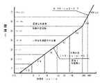
表1の値を、縦軸に震度をとり横軸に加速度の値をとって片対数グラフにすると、直線になる(図2参照)。震度をIとすると、I=2log(α)+0.7。これを河角の式という。 When the values in Table 1 are plotted on a semi-logarithmic graph with seismic intensity on the vertical axis and acceleration on the horizontal axis, a straight line is obtained (see FIG. 2). If the seismic intensity is I, I = 2log (α) +0.7. This is called the Kawasumi formula.
各震度の境界の前後は同じ加速度値であるので、各震度の加速度の対数中心値をとって、簡易地震計の加速度とした。その値を表2に示す。震度7は、500galとした。 Since the acceleration values before and after the boundary of each seismic intensity are the same, the logarithmic central value of the acceleration of each seismic intensity was taken as the acceleration of the simple seismometer. The values are shown in Table 2. The
簡易地震計に使用する球の直径を20mmとしたときの、各震度に対応する丸穴の径を表2の加速度と(5)式を使って計算すると、表2の丸穴径となる。台座に各震度に相当する当該丸穴をあけ、直径を20mmの球を乗せると震度計となる。
直径20mmの球を0.03mmの丸穴に乗せることは、丸穴が隠れて見えないため極めて難しい。丸穴の代わりに、球の直径より大きな球の凹面にすると、球を台座の中心に容易にセットすることができる。凹面の深さを変えて、各震度に設定する。When the diameter of the round hole corresponding to each seismic intensity when the diameter of the sphere used in the simple seismometer is 20 mm is calculated using the acceleration in Table 2 and Equation (5), the round hole diameter in Table 2 is obtained. A seismic intensity meter can be obtained by making a circular hole corresponding to each seismic intensity on the pedestal and placing a sphere with a diameter of 20 mm.
It is extremely difficult to place a sphere having a diameter of 20 mm in a 0.03 mm round hole because the round hole is hidden and cannot be seen. If the concave surface of the sphere larger than the diameter of the sphere is used instead of the round hole, the sphere can be easily set at the center of the pedestal. Change the depth of the concave surface to set each seismic intensity.
凹面にセットされた球は、地震の加速度の大きさおよび震動の周期により台座の上を運動する。加速度の大きさにより、やがて球は台座から飛び出す。
凹面の曲率半径、深さおよび震動周期が判れば、球が台座から飛び出すときの加速度の大きさを計算することができる。
しかし、発生した地震の加速度および周期は計測後判るもので、刻々計算することはできない。The sphere set on the concave surface moves on the pedestal according to the magnitude of the acceleration of the earthquake and the period of the vibration. Depending on the magnitude of the acceleration, the ball will eventually jump out of the pedestal.
If the radius of curvature, depth, and period of vibration of the concave surface are known, the magnitude of acceleration when the sphere jumps out of the pedestal can be calculated.
However, the acceleration and period of the earthquake that occurred are known after measurement and cannot be calculated every moment.
従って、阪神大震災のデータを参考に、震度7の振動数を2.5Hzとし震度1の振動数を経験的に0.8Hzとし、その間を対数目盛で7分割した値を求め、振動数を規格化した。その値を表2の振動数に示す。加速度および振動数から、震動の振幅が求まる。 Therefore, referring to the data of the Great Hanshin Earthquake, the frequency of
簡易地震計用に規格化した振動数および振幅を使って阪神大震災の地震波形記録データを参考に、前震6秒、本震6秒および後震12秒、合計24秒の地震波形を模擬する加振機を製作した。当該模擬加振機を使って、各震度に相当する丸穴径の調整や凹面の曲率半径および深さを求めた。 Using the frequency and amplitude standardized for a simple seismometer, with reference to the earthquake waveform record data of the Great Hanshin Earthquake, excitation that simulates the earthquake waveform of a total of 24 seconds, 6 seconds for the foreshock, 6 seconds for the main shock, and 12 seconds for the aftershock I made a machine. Using this simulated shaker, the adjustment of the round hole diameter corresponding to each seismic intensity and the curvature radius and depth of the concave surface were obtained.
丸穴および凹面の代わりに、縁をつけた皿穴の台座を用意した。縁の高さを変え、模擬加振機で各震度に相当する簡易地震計を完成させた。 Instead of a round hole and a concave surface, a countersunk pedestal with an edge was prepared. The height of the rim was changed, and a simple seismometer corresponding to each seismic intensity was completed with a simulated shaker.
金属製台座の上部に丸穴をあけ、当該丸穴に乗せた金属球が、地震の横揺れ加速度により、金属球が穴から飛び出す地震計において、金属製台座から落下した金属球を金属製台座から電気的に絶縁された金属製受け皿で受け、金属製受け皿と金属製台座と金属球により接点を構成し、当該落下した金属球を電気接点で検出する接点付き簡易地震計を完成させた。 In a seismometer where a metal sphere is drilled from the hole due to the roll acceleration of the earthquake, a metal ball dropped from the metal pedestal is made into a metal pedestal. A simple seismometer with a contact for detecting the falling metal ball with an electrical contact was completed, which was received by a metal saucer electrically insulated from the metal, and a contact was formed by a metal tray, a metal base and a metal ball.
当該電気接点付き簡易地震計により検出された震度を、当該接点で作動する震度表示器および警報装置を使って、集会者に知らしめたり地震発生時刻を記録する装置も完成させた。 We have also completed a device for informing the congregation of the seismic intensity detected by the simple seismometer with electrical contacts and using the seismic intensity indicator and alarm device that operates at the contact points, and recording the earthquake occurrence time.
当該電気接点付き簡易地震計により検出された震度を、当該接点で作動する震度表示器および警報装置へ伝達させる手段として、既知の無線送受信機または商用電源線電送装置を介して、遠隔地の集会者に知らしめたり地震発生時刻を記録する装置も完成させた。 As a means for transmitting the seismic intensity detected by the simple seismometer with electrical contacts to the seismic intensity indicator and alarm device that operates at the contact, it is possible to gather at remote locations via known wireless transceivers or commercial power line transmission devices. We have also completed a device to let people know and record the time of the earthquake.
このようにして、高価なセンサーや信号処理器を必要としない簡便・安価・正確な地震計を提供することができた。 In this way, a simple, inexpensive and accurate seismometer that does not require expensive sensors and signal processors could be provided.
図1は、本発明に係わる原理を図示したものである。図において、直径dの丸穴の上に直径Dの球を乗せ地震が発生して球が横揺れの加速度αを受けると、球は丸穴から飛び出そうとする地震力F=mαを受ける。 FIG. 1 illustrates the principle of the present invention. In the figure, when a sphere having a diameter D is placed on a circular hole having a diameter d and an earthquake occurs and the sphere receives a roll acceleration α, the sphere receives an earthquake force F = mα that attempts to jump out of the circular hole.
横揺れの地震力Fを受けて球が丸穴の一部のp点から飛び出すには、p点における地震による横方向に受けるモーメントMFが重力によるモーメントMgより大きいときである。その臨界の横揺れの加速度αは、MF=Mgと置いて前述の(5)式によって求められる。 In order for the sphere to jump out of the point p at a part of the round hole in response to the rolling earthquake force F, the moment MF received in the lateral direction due to the earthquake at the point p is greater than the moment Mg due to gravity. The critical roll acceleration α is obtained by the above-described equation (5) with MF = Mg.
その結果、地震の横揺れの加速度αは、丸穴の直径dと球の直径Dのみに関係し、球の質量mには関係しない。よって、球は、鋼球でもガラス玉でも良いので、安価なビー玉も使用できる。 As a result, the acceleration α of the roll of the earthquake is related only to the diameter d of the round hole and the diameter D of the sphere, and not to the mass m of the sphere. Therefore, since the ball may be a steel ball or a glass ball, an inexpensive marble can be used.
図2は、地震の震度と加速度の範囲を示した図である。気象庁震度階と呼ばれていて、各震度の加速度を表1に示した。各震度の上限の加速度は次の高震度の下限と同じ値であるので、各震度の中央値をもって当該簡易地震計の加速度とした。各震度に対応する当該加速度を、表2に示した。 FIG. 2 is a diagram showing the seismic intensity and acceleration range of the earthquake. Table 1 shows the acceleration of each seismic intensity. Since the upper limit acceleration of each seismic intensity is the same value as the lower limit of the next high seismic intensity, the median value of each seismic intensity was taken as the acceleration of the simple seismometer. The acceleration corresponding to each seismic intensity is shown in Table 2.
球の直径を20mmとしたとき、各加速度に対応する丸穴の直径は、(5)式で計算される。その結果を、表2の丸穴径に示した。 When the diameter of the sphere is 20 mm, the diameter of the round hole corresponding to each acceleration is calculated by equation (5). The results are shown in the round hole diameter in Table 2.
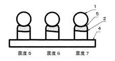
図3は、本発明に係わる簡易地震計の一実施例を示している。同図は、震度5、震度6および震度7に対応する簡易地震計である。同図において、台座2の上部には、各震度に相当する表2の丸穴径の丸穴3があけられている。当該台座2は、基板4と図示していない螺子により固定されている。丸穴3の上には、直径20mmの球1が乗せられている。地震発生時に、球1は震度6の地震があったとき、震度6の本震の前に、震度5の球1が台座2から落下する。震度6の本震時に、震度6の球1が台座2から落下する。震度7の球1は、落下しない。
このようにして、落下した球1のうちの最大震度のものが、発生した地震の震度である。FIG. 3 shows an embodiment of a simple seismometer according to the present invention. This figure is a simple seismometer corresponding to
Thus, the thing of the maximum seismic intensity of the fallen
図4は、本発明に係わる簡易地震計の一実施例を示している。同図は、震度5、震度6および震度7に対応する簡易地震計である。同図において、台座2の上部には、球1の半径10mmより大きな半径25mmで穴加工された球凹面5があけられている。球1を、球凹面5の上に乗せる。球1は、球凹面5の最下部に静止している。
地震発生時、球凹面5の上の球1は、左右に揺れる。地震の加速度が増すと、やがて球1は、球凹面5から飛び出す。球凹面5の深さを変えて、各震度に対応させた。FIG. 4 shows an embodiment of a simple seismometer according to the present invention. This figure is a simple seismometer corresponding to
When an earthquake occurs, the
図5は、本発明に係わる簡易地震計の他の一実施例を示している。同図は、震度5、震度6および震度7に対応する簡易地震計である。同図において、台座2の上部には、縁6で囲まれた皿穴7があけられている。球1を、皿穴7の上に乗せる。
地震発生時、皿穴7の上の球1は、左右に揺れる。地震の加速度が増すと、やがて球1は、縁6から飛び出す。皿穴7の縁6の高さを変えて、各震度に対応させた。FIG. 5 shows another embodiment of a simple seismometer according to the present invention. This figure is a simple seismometer corresponding to
When an earthquake occurs, the
図6は、本発明に係わる電気接点付き簡易地震計の一実施例を示している。同図において、金属製台座2Aの上部には、各震度に相当する表2の丸穴径の丸穴3があけられている。当該金属製台座2Aは、絶縁スリーブ8により電気的に金属製基板4Aと絶縁されて、螺子9により金属製基板4Aに固定されている。 FIG. 6 shows an embodiment of a simple seismometer with electrical contacts according to the present invention. In the figure, a
金属製台座2Aを囲むように、わん状の金属製受け皿10が金属製スタッド11により、金属製台座2Aと接触しないで金属製基板4Aに固定されている。
金属製台座2Aの上部の丸穴3の上に、直径20mmの金属製球1Aを乗せる。地震発生時に、金属球1Aは震度相当の地震があったとき、台座2Aから落下する。A bowl-shaped
A metal ball 1A having a diameter of 20 mm is placed on the
図7は、図6に示した本発明に係わる簡易地震計の動作例を示している。
金属製台座2Aから落下した金属球1Aは、金属製受け皿10で受け止められる。このとき、金属球1Aは、金属製受け皿10と金属製台座2Aとが接触し、電気接点を構成する。これにより電気接点を通る回路から形成され、螺子9からのリード線12および金属製基板4Aからのリード線13により、導通したことを示す電気信号が取り出される。この信号は有線又は無線により震度表示器(図示せず)又は警報装置(図示せず)を作動させることができる。FIG. 7 shows an operation example of the simple seismometer according to the present invention shown in FIG.
The metal ball 1A dropped from the metal pedestal 2A is received by the
丸穴3の丸穴径を変え複数の金属製台座2Aを用意すれば、複数の震度を測れる電気接点付き簡易地震計となる。なお、複数の丸穴を有する金属製台座、金属製受け皿、及び金属球(又は金属薄膜で被覆したガラス球等)を使用して、電気接点を介する電気回路を形成する場合には、信号間の干渉を防ぐように互いに電気絶縁する必要がある。 If the round hole diameter of the
1 球
1A 金属球
2 台座
2A 金属製台座
3 丸穴
4 基板
4A 金属製基板
5 球凹面
6 縁
7 皿穴
8 絶縁スリーブ
9 螺子
10 金属製受け皿
11 金属製スタッド
12 リード線
13 リード線1 sphere
Claims (6)
Translated fromJapanesePriority Applications (1)
| Application Number | Priority Date | Filing Date | Title |
|---|---|---|---|
| JP2005021565AJP2006208231A (en) | 2005-01-28 | 2005-01-28 | Simple seismometer |
Applications Claiming Priority (1)
| Application Number | Priority Date | Filing Date | Title |
|---|---|---|---|
| JP2005021565AJP2006208231A (en) | 2005-01-28 | 2005-01-28 | Simple seismometer |
Publications (1)
| Publication Number | Publication Date |
|---|---|
| JP2006208231Atrue JP2006208231A (en) | 2006-08-10 |
Family
ID=36965256
Family Applications (1)
| Application Number | Title | Priority Date | Filing Date |
|---|---|---|---|
| JP2005021565AWithdrawnJP2006208231A (en) | 2005-01-28 | 2005-01-28 | Simple seismometer |
Country Status (1)
| Country | Link |
|---|---|
| JP (1) | JP2006208231A (en) |
Cited By (5)
| Publication number | Priority date | Publication date | Assignee | Title |
|---|---|---|---|---|
| JP2009156812A (en)* | 2007-12-27 | 2009-07-16 | Toshiba Corp | Earthquake detection device |
| JP2010164325A (en)* | 2009-01-13 | 2010-07-29 | Taisei Corp | System for predicting seismic vibration |
| JP2014167331A (en)* | 2013-02-28 | 2014-09-11 | Hitachi Automotive Systems Ltd | Attenuation force change-over seismic base isolation system |
| CN106838366A (en)* | 2017-04-12 | 2017-06-13 | 荆门创佳机械科技有限公司 | A kind of major diameter gas pipeline earthquake disaster shutoff valve |
| KR102039589B1 (en)* | 2019-06-14 | 2019-11-01 | 청석전기 주식회사 | Apparatus for detecting earthquake |
- 2005
- 2005-01-28JPJP2005021565Apatent/JP2006208231A/ennot_activeWithdrawn
Cited By (5)
| Publication number | Priority date | Publication date | Assignee | Title |
|---|---|---|---|---|
| JP2009156812A (en)* | 2007-12-27 | 2009-07-16 | Toshiba Corp | Earthquake detection device |
| JP2010164325A (en)* | 2009-01-13 | 2010-07-29 | Taisei Corp | System for predicting seismic vibration |
| JP2014167331A (en)* | 2013-02-28 | 2014-09-11 | Hitachi Automotive Systems Ltd | Attenuation force change-over seismic base isolation system |
| CN106838366A (en)* | 2017-04-12 | 2017-06-13 | 荆门创佳机械科技有限公司 | A kind of major diameter gas pipeline earthquake disaster shutoff valve |
| KR102039589B1 (en)* | 2019-06-14 | 2019-11-01 | 청석전기 주식회사 | Apparatus for detecting earthquake |
Similar Documents
| Publication | Publication Date | Title |
|---|---|---|
| MXPA06013523A (en) | Convective accelerometer. | |
| KR101938825B1 (en) | Omnidirectional vibration sensor and earthquake disaster alarm system using it | |
| US5539387A (en) | Earthquake sensor | |
| US20020073564A1 (en) | Tilt detector | |
| JP2006208231A (en) | Simple seismometer | |
| CN211668493U (en) | Building slope real-time supervision device | |
| JPS5925163B2 (en) | vibration detection device | |
| JPH1062234A (en) | Simple earthquake-sensing warning device | |
| CA2214440A1 (en) | Earthquake sensor | |
| MXPA97006603A (en) | Sensor of sis | |
| US3490153A (en) | Inclinometer | |
| AU2015210513A1 (en) | Measuring device with magnetically coupled data transmitting and data reading parts | |
| CN101777239A (en) | Earthquake emergency rescue alarm | |
| JP2006003231A (en) | Earthquake sensor | |
| CN105487108A (en) | Low-natural frequency stable inverted pendulum column structure | |
| US12333920B2 (en) | Earthquake detection and alarm unit and system | |
| US5546076A (en) | Earth-tremor-responsive light | |
| JP2022025327A (en) | Earthquake-time shake data acquisition device and degree-of-disaster assessment system | |
| EP1560042A2 (en) | Sensor for detecting vibrations, particularly seismic waves | |
| JPH08315274A (en) | Earthquake detecting alarm | |
| KR101940301B1 (en) | Electric horizontal sensor using gravity | |
| CN203350461U (en) | earthquake detector | |
| JP2861109B2 (en) | Seismic device | |
| CN212808643U (en) | Heavy hammer seismic source trigger device for engineering seismic exploration | |
| RU2136049C1 (en) | Pendulum-type alarm sensor |
Legal Events
| Date | Code | Title | Description |
|---|---|---|---|
| A300 | Withdrawal of application because of no request for examination | Free format text:JAPANESE INTERMEDIATE CODE: A300 Effective date:20080401 |