JP2006208099A - Control device for automatic analyzer - Google Patents
Control device for automatic analyzerDownload PDFInfo
- Publication number
- JP2006208099A JP2006208099AJP2005018592AJP2005018592AJP2006208099AJP 2006208099 AJP2006208099 AJP 2006208099AJP 2005018592 AJP2005018592 AJP 2005018592AJP 2005018592 AJP2005018592 AJP 2005018592AJP 2006208099 AJP2006208099 AJP 2006208099A
- Authority
- JP
- Japan
- Prior art keywords
- program
- screen
- command
- control device
- automatic analyzer
- Prior art date
- Legal status (The legal status is an assumption and is not a legal conclusion. Google has not performed a legal analysis and makes no representation as to the accuracy of the status listed.)
- Pending
Links
Images


Landscapes
- Automatic Analysis And Handling Materials Therefor (AREA)
Abstract
Description
Translated fromJapanese本発明は、分析者により予め作成されたプログラムに従って分析機器を自動的に動作させて、試料に対する分析・測定に関わる処理を実行させる自動分析機器の制御装置に関する。 The present invention relates to a control apparatus for an automatic analyzer that automatically operates an analyzer according to a program created in advance by an analyst, and executes processing related to analysis / measurement on a sample.
液体クロマトグラフでは、予めバイアル瓶に準備された多数の液体試料の中から所定の順番で分析対象の試料を自動的に選択して採取しカラムに導入するために、オートサンプラ(液体試料自動サンプリング装置)が使用される。こうしたオートサンプラの動作を設定する方法として、例えば特許文献1に記載のように、一連の分析毎に様々な機構の動きを指定するコマンドを分析者が適宜組み合わせてプログラムを作成し、そのプログラムに従った動作を行わせる方法がある。従来、こうしたプログラムの作成は、分析システムの統括的な制御を司るコンピュータにおいて、モニタ画面上に表示された数値入力画面で各種の数値条件を入力したり、或いはコマンドの編集画面上でコマンドの入力や変更、削除等の編集を実行することにより行われる。 In a liquid chromatograph, an autosampler (automatic sampling of liquid samples) is used to automatically select and collect samples to be analyzed from a number of liquid samples prepared in advance in a vial in a predetermined order. Device). As a method for setting the operation of such an autosampler, for example, as described in
上記動作設定方法によれば、例えばその装置のメーカーにより予め用意されたシーケンスに従った動作を行う場合と異なり、分析者が所望する細かい条件で以て柔軟な動作を行わせることができるという利点がある。その反面、分析者はプログラムを構成するコマンドで指定される動作の内容やそのコマンドに伴う各種の数値パラメータ(例えば回数、時間、量など)の意味付けなどを理解している必要があり、操作に或る程度の熟練を要する。 According to the above operation setting method, for example, unlike the case of performing an operation according to a sequence prepared in advance by the manufacturer of the apparatus, an advantage that a flexible operation can be performed under the fine conditions desired by the analyst. There is. On the other hand, the analyst needs to understand the contents of the operations specified by the commands that make up the program and the meaning of various numerical parameters (for example, the number of times, time, amount, etc.) associated with the commands. Requires some skill.
近年、液体クロマトグラフを始めとする分析装置での分析対象の試料はその種類が非常に多様化及び複雑化している。こうした試料に対して正確な分析を行うためには、単に液体試料を選択的に採取するだけでなく、採取した試料をカラムに導入する前に、例えば成分の濃縮や希釈、不要成分・妨害成分の除去、或いは試薬の添加など、様々な前処理を行わなければならない場合がある。こうした前処理を実行するためにオートサンプラの機構系やその動作は一層複雑になり、その動作を指定するプログラムも非常に複雑で長いものになってくる。そのため、たとえ熟練者であっても全てのコマンドを覚えていてミス無くプログラムを作成するのは難しくなりつつある。まして、コマンドを覚えていない未熟練者ではプログラムを作成することは殆ど不可能であり、実際に実行したい処理動作に近い条件で動作する既存のプログラムを使用せざるを得ず、必ずしも最適な条件での分析が行えないことになる。 In recent years, the types of samples to be analyzed by analyzers such as liquid chromatographs have become very diversified and complicated. In order to perform accurate analysis on such samples, not only liquid samples can be collected selectively, but also before the collected samples are introduced into the column, for example, concentration or dilution of components, unnecessary components / interfering components In some cases, various pretreatments such as removal of a reagent or addition of a reagent have to be performed. In order to execute such preprocessing, the mechanism system of the autosampler and its operation become more complicated, and the program for specifying the operation becomes very complicated and long. Therefore, even if it is an expert, it is becoming difficult to memorize all commands and to create a program without mistakes. Furthermore, it is almost impossible for an unskilled person who does not remember commands to create a program, and an existing program that operates under conditions close to the processing operation that is actually desired must be used. It will not be possible to analyze in
本発明は上記課題を解決するために成されたものであり、その主な目的は、分析機器の動作を制御するためのプログラム作成の作業を簡単に行えるようにし、特に未熟練者であっても所望の分析を行うためのプログラムを作成することができる自動分析機器の制御装置を提供することにある。 The present invention has been made to solve the above-mentioned problems, and its main purpose is to make it easy to create a program for controlling the operation of an analytical instrument. Another object of the present invention is to provide a control device for an automatic analyzer that can create a program for performing a desired analysis.
上記課題を解決するために成された本発明は、分析者により予め作成されたプログラムに従って分析機器を自動的に動作させて、試料に対する分析・測定に関わる処理を実行させる自動分析機器の制御装置であって、
a)それぞれ動作内容が定義されたコマンドを分析者が任意に組み合わせて前記プログラムを作成するための編集画面をモニタ画面内に表示させる表示制御手段と、
b)該編集画面上で分析者が所定の指示・操作を行うための操作手段と、
c)前記編集画面内に配置された所定のボタンが前記操作手段を用いて操作されたとき、既に登録されているプログラムを特定するプログラム特定情報と該プログラムに付随して任意に入力可能なコメント情報とを含む参照情報を前記モニタ画面上に表示するとともに、該参照情報が表示されている状態で前記プログラム特定情報の任意の一つが選択されたとき、選択されたプログラムを構成するコマンドを呼び出して前記編集画面内に表示するプログラム作成支援手段と、
を備えることを特徴としている。In order to solve the above-mentioned problems, the present invention provides a control device for an automatic analyzer that automatically operates an analyzer in accordance with a program created in advance by an analyst and executes processing related to analysis / measurement on a sample. Because
a) display control means for displaying an edit screen for creating the program by arbitrarily combining commands, each of which defines operation contents, on the monitor screen;
b) operation means for the analyst to perform predetermined instructions / operations on the editing screen;
c) Program specific information for specifying a program that has already been registered and a comment that can be arbitrarily input in association with the program when a predetermined button arranged in the edit screen is operated using the operation means. In addition to displaying reference information including information on the monitor screen, when any one of the program specifying information is selected while the reference information is displayed, a command that configures the selected program is called. Program creation support means for displaying in the editing screen;
It is characterized by having.
本発明は様々な自動分析機器に適用することが可能であるが、特に、複数の処理・作業を時系列的に順次実行するものであって、且つその処理・作業を自在に組み替えることが要求されるような分析機器に好適である。こうした分析機器の一例として、複数用意された液体試料を選択して採取し、採取した試料に対し必要に応じて所定の前処理を実行した上で液体クロマトグラフのカラムに導入する液体試料自動サンプリング装置を挙げることができる。 The present invention can be applied to various automatic analyzers. In particular, it is intended to sequentially execute a plurality of processes / work in time series, and it is required to freely recombine the processes / work. It is suitable for such an analytical instrument. As an example of such an analytical instrument, a plurality of prepared liquid samples are selected and sampled, and a liquid sample automatic sampling that is introduced into a liquid chromatograph column after performing predetermined pretreatment on the collected samples as necessary. A device can be mentioned.
本発明に係る自動分析機器の制御装置では、分析者(オペレータ)が所定の操作を行うと表示制御手段はプログラム作成用の編集画面をモニタ画面上に表示させる。基本的には、分析者がこの編集画面内でコマンドの入力、削除、或いはコピー等の編集作業を行い、且つ、そのコマンドに対応した処理動作を行う際に何らかの数値パラメータが必要となるものについてパラメータの設定も行うことにより、プログラムを作成することができる。したがって、可能であれば分析者は上記プログラム作成支援手段を用いることなく1から全てコマンドを入力していってプログラムを作成してもよい。 In the control device for an automatic analyzer according to the present invention, when an analyst (operator) performs a predetermined operation, the display control means displays an edit screen for creating a program on the monitor screen. Basically, when an analyst performs editing operations such as inputting, deleting, or copying a command in this editing screen, and some numerical parameters are required when performing processing operations corresponding to the command A program can be created by setting parameters. Therefore, if possible, the analyst may create a program by inputting all commands from 1 without using the program creation support means.
これに対し、プログラム作成支援手段の機能を使用したい場合には、分析者は編集画面内に配置された所定のボタンを例えば操作手段としてのマウスでクリック操作する。するとプログラム作成支援手段はこの操作を受けて、過去に登録されているプログラムを特定するプログラム特定情報と該プログラムに付随して任意に入力可能なコメント情報とを含む参照情報を例えば一覧表形式で以てモニタ画面上に表示させる。プログラム特定情報とは例えばそのプログラムを登録する際に付与されたファイル名である。またコメント情報は、そのプログラムを登録する際にその登録者がプログラムの内容や適用可能な試料種類などについて一目で判るように自由に記述したものである。分析者はこのコメント情報を参考にして、例えば自分が実行したいと考えている分析に最も近いプログラムを選定し、そのプログラム特定情報をクリック操作する。すると、プログラム作成支援手段はそのプログラムを読み出してきて該プログラムを構成する1乃至複数のコマンドを編集画面内に表示する。したがって、分析者は表示されたこの一連のコマンドを一種のテンプレートとして、不要なコマンドの削除、必要なコマンドの追加、コマンドの入れ替え、等の編集作業を行うことにより新たなプログラムを作成することができる。なお、新たに作成したプログラムを追加して登録できるようにしておくことにより、次回のプログラム作成時にはそのプログラムもテンプレートとして利用することができる。 On the other hand, when the user wants to use the function of the program creation support means, the analyst clicks a predetermined button arranged in the editing screen with, for example, a mouse as an operation means. Then, in response to this operation, the program creation support means obtains reference information including program identification information for identifying a program registered in the past and comment information that can be arbitrarily input along with the program, for example, in a list format. Thus, it is displayed on the monitor screen. The program specifying information is, for example, a file name given when registering the program. The comment information is freely described so that the registrant can know at a glance the contents of the program and applicable sample types when registering the program. The analyst selects, for example, a program closest to the analysis that he / she wishes to perform with reference to the comment information, and clicks the program specifying information. Then, the program creation support means reads the program and displays one or more commands constituting the program in the edit screen. Therefore, the analyst can use this series of displayed commands as a kind of template to create a new program by performing editing operations such as deleting unnecessary commands, adding necessary commands, replacing commands, etc. it can. In addition, by newly registering a newly created program so that it can be registered, the program can be used as a template when creating the next program.
このように本発明に係る自動分析機器の制御装置によれば、自分が作成したいプログラムと比較的近いプログラムが登録されていれば、そのプログラムを元に編集作業を行うだけで所望の分析を実行するためのプログラムを作成することができる。しかも、そうした過去に登録されているプログラムに関する情報を呼び出すためのボタンが編集画面内に配置されているため、操作が簡単であって分かり易い。これにより、分析機器を動作させるためのプログラムの作成に掛かる労力を軽減することができるとともに、コマンドを1から記述するほど知識や経験の無い者でも、所望の分析を行うべく細かな条件を設定したプログラムを作成することができる。 As described above, according to the control device for an automatic analyzer according to the present invention, if a program that is relatively close to the program that the user wants to create is registered, a desired analysis can be performed simply by performing editing based on the program. A program can be created. In addition, since buttons for calling up information related to programs registered in the past are arranged in the editing screen, the operation is simple and easy to understand. As a result, the effort required to create a program for operating the analytical instrument can be reduced and detailed conditions can be set to perform the desired analysis even for those who have no knowledge or experience to describe the command from 1. Program can be created.
また、未熟練者にとっては各コマンドに定義付けられた動作内容自体も不明であることが多いから、前記プログラム作成支援手段は、前記編集画面内に表示されているプログラムの各コマンドが選択指示されたとき、そのコマンドの動作内容に関連した情報を参照情報として前記モニタ画面上に表示させる構成とすることが好ましい。 In addition, since the operation content defined for each command is often unknown to an unskilled person, the program creation support means selects and instructs each command of the program displayed in the editing screen. It is preferable that information related to the operation content of the command is displayed on the monitor screen as reference information.
この構成によれば、一々取扱説明書等を参照しなくても編集画面上での簡単な操作によって、覚えていないコマンドに定義付けられた動作内容を確認しながら、コマンドの編集作業を行うことができる。したがって、未熟練者でも無理なく且つ効率良くプログラム作成を行うことができる。 According to this configuration, command editing work can be performed while confirming the operation content defined for a command that is not remembered by simple operations on the editing screen without referring to the instruction manual etc. Can do. Accordingly, even an unskilled person can create a program without difficulty.
また、作成時にプログラムを十分に確認した場合でも、そのプログラムに従った分析を実行してみると分析者の意図とは異なる動作となり、期待していた内容と異なる分析結果を生じる場合もある。また、いくら細心の注意を払っていても入力ミス等によりプログラムが完全には動作しない場合もある。そこで本発明の一態様として、好ましくは、前記編集画面内に表示されているプログラムに従った動作を試験的に実行させることを指示するためのボタンを前記編集画面内に配置し、前記操作手段を用いた該ボタン操作に応じて前記編集画面内に表示されているプログラムを構成するコマンドに対応した動作を順次実行するように分析機器を制御する試験動作実行制御手段を備える構成とするとよい。 Even when the program is sufficiently confirmed at the time of creation, when an analysis according to the program is executed, the operation differs from the analyst's intention and an analysis result different from the expected content may be generated. Also, no matter how much care is taken, the program may not operate completely due to an input error or the like. Therefore, as one aspect of the present invention, preferably, a button for instructing to experimentally execute an operation according to the program displayed in the editing screen is arranged in the editing screen, and the operation means It is preferable to include a test operation execution control means for controlling the analytical instrument so as to sequentially execute operations corresponding to commands constituting the program displayed in the editing screen in response to the button operation using.
この構成によれば、編集画面上で作成したプログラムを登録する前に簡単な操作で以て試験的に実行させることにより、そのプログラムが意図した通りの動作を行うものであるか否かをチェックすることができる。 According to this configuration, before registering a program created on the edit screen, it is possible to check whether the program performs the intended operation by executing it with a simple operation on a trial basis. can do.
さらに好ましくは、前記試験動作実行制御手段は、前記試験的な動作の実行中にエラーが発生した場合に、該エラーの内容に関連した情報を前記モニタ画面上に自動的に表示させる構成とするとよい。「エラーの内容に関連した情報」とは具体的にはそのエラーの内容や原因を説明したり、そのエラーを解消するための方法(例えばコマンドの修正の仕方など)を説明する一種のヘルプ画面とすればよい。 More preferably, the test operation execution control means is configured to automatically display information related to the content of the error on the monitor screen when an error occurs during the execution of the test operation. Good. “Information related to error contents” is a kind of help screen that explains the details and cause of the error, and how to solve the error (for example, how to correct the command) And it is sufficient.
この構成によれば、上記のような試験的な動作の際に何らかのエラーが発生したとき、すぐにその原因に立ち戻ってプログラムを修正することができる。したがって、プログラムのバグの修正を含め、プログラムの作成を効率良く行うことができる。特に、未熟練者では作成したプログラムが正確に動作しないときにその対処に戸惑うことが多いが、画面上に表示される指示に従って修正を行えばよいので負担が軽減される。 According to this configuration, when an error occurs during the test operation as described above, it is possible to immediately return to the cause and correct the program. Therefore, it is possible to efficiently create a program including correction of bugs in the program. In particular, an unskilled person is often confused when a program that has been created does not operate correctly, but the burden can be reduced because corrections can be made in accordance with instructions displayed on the screen.
以下、本発明に係る自動分析機器の制御装置の一実施例として、液体クロマトグラフ用のオートサンプラを制御する場合を例に挙げて説明する。図1は本実施例の制御装置による制御対象であるオートサンプラを含む液体クロマトグラフ分析システムの全体構成図である。 Hereinafter, a case of controlling an autosampler for a liquid chromatograph will be described as an example as an embodiment of a control device for an automatic analyzer according to the present invention. FIG. 1 is an overall configuration diagram of a liquid chromatograph analysis system including an autosampler to be controlled by the control device of this embodiment.
この液体クロマトグラフ分析システムでは、分析を遂行するためのユニットとして、移動相容器1から移動相を吸引して一定流量で送給する送液ポンプ2、ラックに用意された多数の液体試料から所定の順序で試料を選択して採取し、必要に応じて濃縮等の前処理を実行した後に送液ポンプ2により送給されてきた移動相中に注入するオートサンプラ3、移動相に乗った液体試料が送り込まれるカラム5を内部に有し該カラム5を温度制御するカラムオーブン4、カラム5で分離された試料中の各成分を検出する検出器6、を備え、これら各ユニットはパーソナルコンピュータ8による指示に基づいて分析制御部7により制御される。即ち、パーソナルコンピュータ8は分析制御部7を介して上記各ユニットを制御するが、ここでは、特にオートサンプラが本発明における分析機器に相当し、パーソナルコンピュータ8が本発明における制御装置に相当する。 In this liquid chromatograph analysis system, as a unit for performing analysis, a
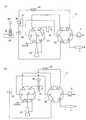
図2はオートサンプラ3の構成の一例、及び動作を説明するための流路構成図である。図2において、インジェクションバルブ(高圧バルブ)30は6つのポート30a〜30fを有する回転式の6ポート2ポジション流路切換バルブであって、切換え操作により、隣接する2つのポートが選択的に接続される。即ち、図2(a)中の実線又は点線の2つの接続の組み合わせが切換え可能とされる。一方、低圧バルブ31は7つのポート31a〜31gを有する回転式の7ポート6ポジションバルブであり、計量ポンプ32が接続された共通ポート31gは他の6つのポート31a〜31fのいずれか1つに連結され、それに連動してポート31a〜31fの中の隣接する所定の2つのポートが連結される。例えば図2(a)中に実線で示すように共通ポート31gとポート31bとが連結されるときにはポート31aと31fとが連結される。 FIG. 2 is an example of the configuration of the
インジェクションバルブ30のポート30bにはカラム5へ至るカラム流路が、ポート30cには送液ポンプ2により移動相が供給される移動相流路が接続される。また、ポート30dにはサンプルループ34接続され、さらにニードル36、インジェクションポート35を介してポート30aに接続される。ポート30e及びポート30fは、それぞれ低圧バルブ31のポート31b及びポート31cに接続される。その低圧バルブ31のポート31aには洗浄ポート33が接続され、ポート31eは計量ポンプ32に接続され、さらにポート31dには洗浄液が供給される。液体試料が貯留された小型のバイアル瓶39は試料ラック38に多数収容されている。ニードル36は、移動機構37により水平方向及び垂直方向にそれぞれ移動可能となっており、バイアル瓶39上及び洗浄ポート33上に移動すると共にそれぞれの液中に挿入可能である。 A column flow path leading to the
このオートサンプラ3における試料導入時の基本的な動作シーケンスを説明する。試料採取時には、インジェクションバルブ30及び低圧バルブ31は図2(a)中の実線で示す接続状態に切り替えられ、ニードル36はバイアル瓶39上に移動されてその液体試料中に挿入される(符号36’の位置)。その状態で、計量ポンプ32のプランジャが引かれると、計量ポンプ32からニードル36に至る流路中に満たされている移動相(又は同じ成分である洗浄液)を介してバイアル瓶39から液体試料が吸引され、その液体試料はサンプルループ34中に保持される。液体試料の採取量は計量ポンプ32の吸引量に等しい。 A basic operation sequence at the time of sample introduction in the
試料採取後、ニードル36はインジェクションポート35上の位置に戻されてインジェクションポート35に接続される。また、インジェクションバルブ30は図2(a)中の点線で示す接続状態に切り換えられる。すると、送液ポンプ2から送給された移動相が、サンプルループ34、ニードル36、インジェクションポート35を通ってカラム5へ送られる。この際、移動相と共に、先にサンプルループ34中に保持された液体試料がカラム5へと送り込まれる。 After sampling, the
こうした試料吸引によって液体試料が付着したニードル36の洗浄は次のようにして行われる。即ち、インジェクションバルブ30及び低圧バルブ31は図2(b)中の実線で示す接続状態に切り換えられる。そして、計量ポンプ32のプランジャが引かれてシリンジ内に洗浄液が吸引される。その後にインジェクションバルブ30及び低圧バルブ31が共に図2(a)中の点線で示す接続状態に切り換えられ、プランジャが押されて計量ポンプ32から洗浄液が吐出されると、洗浄液は洗浄ポート33に導入されて満たされ、余分の洗浄液は洗浄ポート33の排液口から排出される。次に、ニードル36を図2(b)中に示すように洗浄ポート33上に移動させて洗浄ポート33に貯留された洗浄液中に浸漬させ、一定時間、ニードル36を洗浄した後にインジェクションポート35まで戻す。 Cleaning of the
上記動作は最も基本的な動作のみであり、試料中の目的成分の濃縮や試薬の添加などの前処理が加わるとさらにその動作は煩雑になるが、いずれにしても、オートサンプラ3では一連の動作を実行する際にバルブ30、31、計量ポンプ32、移動機構37などの各機構系の動作を順番に実行してゆくことになる。こうした動作を制御するために、1つ1つの動作に対応したコマンドが定義され、パーソナルコンピュータ8上でそのコマンドを組み合わせたプログラムを作成してそのプログラムを実行させることで、上記のようなオートサンプラ3での一連の動作が達成される。本実施例の構成では、そうしたプログラムの作成を容易に行うために、パーソナルコンピュータ8にプログラム作成支援ツール9が用意されている。プログラム作成支援ツール9は実際には、操作部10やモニタ11と関連したマン−マシンインターフェースを含むパーソナルコンピュータ8上で動作するソフトウエアである。 The above operation is only the most basic operation. If pretreatment such as concentration of a target component in a sample or addition of a reagent is added, the operation becomes more complicated. When the operation is executed, the operation of each mechanism system such as the
次に、図3〜図7を参照して、パーソナルコンピュータ8を用いてオートサンプラ3の動作制御用のプログラムを作成する際の手順の一例を説明する。図3はプログラム作成時の典型的な手順の一例を示すフローチャート、図4〜図7はその際にモニタ11の画面上に表示される表示画面の一例を示す図である。 Next, an example of a procedure for creating a program for controlling the operation of the
まず、分析者が操作部10により所定の操作を行うことにより、モニタ11の画面上に図4に示すようなプログラム作成用編集画面100を表示させる(ステップS1)。この編集画面を新たに開いたときには、編集対象であるプログラムの内容を示すプログラムリスト101は空欄である。このプログラムリスト101の各行にそれぞれコマンドを入力してゆくことによりプログラムを作成することもできるが、より簡単な方法としては、分析者は編集画面100内に配置されているプログラム参照ボタン102を操作部10により、具体的にはマウス等のポインティングデバイスによりクリック操作する(ステップS2)。すると、プログラム作成支援ツール9が作動して、図5に示すようなテンプレートリスト110が開く(ステップS3)。このテンプレートリスト110には、既に登録されているプログラムのファイル名111とそのプログラムに付随した説明等を任意に記述することが可能なコメント欄112とが一覧表形式で含まれる。分析者はこのコメント欄112の記述内容を参考にして、所望の動作に近い内容のプログラムを選び、操作部10によりそのプログラムのファイル名を選択指示する(ステップS4)。 First, the analyst performs a predetermined operation with the
すると、プログラム作成支援ツール9は選択されたファイル名のプログラムを所定の記憶領域から読み出し、編集画面100内のプログラムリスト101にそのプログラムを構成するコマンドを図4中に示すように表示する(ステップS5)。このコマンドや各コマンドにおいて設定すべきパラメータを分析者が適宜編集することにより所望の分析動作を行うためのプログラムを作成するわけであるが(ステップS6)、プログラムリスト101に表示されているコマンドについてその動作内容や指定すべきパラメータの意味などが不明である場合(ステップS7でYes)、分析者は操作部10により任意のコマンド行を選択した上でクリック操作を行う(ステップS8)。例えば「exrinse」というコマンドを選択指示すると、図7に示すように、そのコマンドの動作内容の詳細な説明とそのコマンドにおいて設定すべきパラメータの意味を解説したコマンドヘルプ画面130が開く(ステップS9)。したがって、1つ1つのコマンドについてコマンドヘルプ画面130によりその動作内容を理解した上で、コマンド編集を行うことができる。 Then, the program
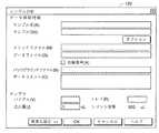
全ての編集作業が一通り終了したならば(ステップS10でYes)、分析者は操作部10により編集画面100内に配置されている動作確認ボタン103をクリック操作する(ステップS11)。すると、図6に示すような動作確認用画面120が開くから(ステップS12)、分析者は必要に応じて例えば注入量等のパラメータを変更してOKボタンをクリック操作する(ステップS13)。この操作により、パーソナルコンピュータ8は、編集画面100のプログラムリスト101に記載されているプログラムに従って分析制御部7を介してオートサンプラ3を試験的に動作させる。即ち、プログラムの各コマンドに対応した動作が順次実行される(ステップS14)。 When all the editing operations are completed (Yes in Step S10), the analyst clicks the
動作に問題が無い場合には最後のコマンドまで順次動作が実行されるが、途中で何らかの問題が発生した場合には(ステップS15でYes)、動作は中断されてその不具合(エラー)に応じたトラブルシューティング画面が自動的に開く(ステップS19)。トラブルシューティング画面には、そのエラーの内容を説明するとともに、そのエラーを解消するための対処策としてコマンドの修正やパラメータの変更などの指示が表示される。したがって、分析者はこのトラブルシューティング画面の指示に従ってコマンドを修正すればよい。もちろん、そうしてプログラムを修正した上で、再度、動作確認を実行することができる。 If there is no problem in the operation, the operation is sequentially executed until the last command. However, if any problem occurs in the middle (Yes in step S15), the operation is interrupted and the error (error) is met. The trouble shooting screen is automatically opened (step S19). On the troubleshooting screen, the details of the error are explained, and instructions such as command correction and parameter change are displayed as countermeasures for solving the error. Therefore, the analyst may correct the command according to the instruction on the troubleshooting screen. Of course, the operation check can be executed again after correcting the program.
エラー無く動作が終了したならば(ステップS16)、プログラムがミス無く且つ目的を達成するように記述されていることが確認できたから、編集画面100内に配置されている登録ボタン104を操作部10によりクリック操作する(ステップS17)。それによって、その時点で編集画面100のプログラムリスト101に表示されているプログラムが記憶領域に登録される(ステップS18)。その際には、分析者が任意のファイル名を設定し、且つそのプログラムに対応した任意のコメントを入力することができる。もちろん、こうして新たに登録したプログラムは次にテンプレートリスト110を表示させる際にはそのリストに加えられ、テンプレートとして利用することが可能となる。 If the operation is completed without an error (step S16), it can be confirmed that the program is written without error and achieves the purpose, and therefore the
以上のように本実施例の構成によれば、プログラムリスト101が表示されるプログラム作成用編集画面100内に配置されている各ボタンのクリック操作により、プログラム作成に必要な様々な情報を閲覧したり取り込んだりすることができる。したがって、その操作が非常に分かり易く、プログラム作成に未熟練な者でもあまり躊躇することなく作業に取り組むことができる。 As described above, according to the configuration of the present embodiment, various information necessary for program creation is browsed by clicking each button arranged in the program
なお、上記実施例は本発明の一例であって、本発明の趣旨に沿った範囲で適宜変形、修正、追加を行っても本発明に包含されることは明らかである。 It should be noted that the above embodiment is an example of the present invention, and it is obvious that the present invention is encompassed by the present invention even if appropriate modifications, corrections and additions are made within the scope of the present invention.
1…移動相容器
2…送液ポンプ
3…オートサンプラ
30…インジェクションバルブ
31…低圧バルブ
32…計量ポンプ
33…洗浄ポート
34…サンプルループ
35…インジェクションポート
36…ニードル
37…移動機構
38…試料ラック
39…バイアル瓶
4…カラムオーブン
5…カラム
6…検出器
7…分析制御部
8…パーソナルコンピュータ
9…プログラム作成支援ツール
10…操作部
11…モニタ
100…プログラム作成用編集画面
101…プログラムリスト
102…プログラム参照ボタン
103…動作確認ボタン
104…登録ボタン
110…テンプレートリスト
111…ファイル名
112…コメント欄
120…動作確認用画面
130…コマンドヘルプ画面
DESCRIPTION OF
Claims (5)
Translated fromJapanesea)それぞれ動作内容が定義されたコマンドを分析者が任意に組み合わせて前記プログラムを作成するための編集画面をモニタ画面内に表示させる表示制御手段と、
b)該編集画面上で分析者が所定の指示・操作を行うための操作手段と、
c)前記編集画面内に配置された所定のボタンが前記操作手段を用いて操作されたとき、既に登録されているプログラムを特定するプログラム特定情報と該プログラムに付随して任意に入力可能なコメント情報とを含む参照情報を前記モニタ画面上に表示するとともに、該参照情報が表示されている状態で前記プログラム特定情報の任意の一つが選択されたとき、選択されたプログラムを構成するコマンドを呼び出して前記編集画面内に表示するプログラム作成支援手段と、
を備えることを特徴とする自動分析機器の制御装置。A control device for an automatic analyzer that automatically operates an analyzer according to a program created in advance by an analyst, and executes processing related to analysis and measurement of a sample.
a) display control means for displaying an edit screen for creating the program by arbitrarily combining commands, each of which defines operation contents, on the monitor screen;
b) operation means for the analyst to perform predetermined instructions / operations on the editing screen;
c) Program specific information for specifying a program that has already been registered and a comment that can be arbitrarily input in association with the program when a predetermined button arranged in the edit screen is operated using the operation means. In addition to displaying reference information including information on the monitor screen, when any one of the program specifying information is selected while the reference information is displayed, a command that configures the selected program is called. Program creation support means for displaying in the editing screen;
A control device for an automatic analyzer, comprising:
The analytical instrument is an automatic liquid sample sampling device that selects and collects a plurality of prepared liquid samples, performs a predetermined pretreatment on the collected samples as necessary, and introduces the sample into a liquid chromatograph column. The control device for an automatic analyzer according to any one of claims 1 to 4, wherein:
Priority Applications (1)
| Application Number | Priority Date | Filing Date | Title |
|---|---|---|---|
| JP2005018592AJP2006208099A (en) | 2005-01-26 | 2005-01-26 | Control device for automatic analyzer |
Applications Claiming Priority (1)
| Application Number | Priority Date | Filing Date | Title |
|---|---|---|---|
| JP2005018592AJP2006208099A (en) | 2005-01-26 | 2005-01-26 | Control device for automatic analyzer |
Publications (1)
| Publication Number | Publication Date |
|---|---|
| JP2006208099Atrue JP2006208099A (en) | 2006-08-10 |
Family
ID=36965137
Family Applications (1)
| Application Number | Title | Priority Date | Filing Date |
|---|---|---|---|
| JP2005018592APendingJP2006208099A (en) | 2005-01-26 | 2005-01-26 | Control device for automatic analyzer |
Country Status (1)
| Country | Link |
|---|---|
| JP (1) | JP2006208099A (en) |
Cited By (9)
| Publication number | Priority date | Publication date | Assignee | Title |
|---|---|---|---|---|
| JP2010518382A (en)* | 2007-02-02 | 2010-05-27 | ベックマン・コールター・インコーポレーテッド | System and method for testing automatic verification rules |
| JP2010175454A (en)* | 2009-01-30 | 2010-08-12 | Yabegawa Denki Kogyo Kk | Fluid transfer device, fluid transfer method, program, and recording medium |
| JP2011185826A (en)* | 2010-03-10 | 2011-09-22 | Shimadzu Corp | Analyzing system for liquid chromatograph and control program for the system |
| CN106370759A (en)* | 2016-08-25 | 2017-02-01 | 贵州电网有限责任公司电力科学研究院 | Linkage method for transformer oil chromatographic full-auto sample injection apparatus and chromatography work station software |
| JP2017227491A (en)* | 2016-06-21 | 2017-12-28 | 株式会社島津製作所 | Liquid chromatograph |
| US10444207B2 (en) | 2015-12-10 | 2019-10-15 | Shimadzu Corporation | Liquid chromatograph analyzer control system |
| CN112611878A (en)* | 2019-10-04 | 2021-04-06 | 日本株式会社日立高新技术科学 | Control device for automatic sampler and automatic measurement system |
| JP2022076610A (en)* | 2020-11-10 | 2022-05-20 | 株式会社島津製作所 | Automatic sample injection device |
| CN114527041A (en)* | 2020-10-30 | 2022-05-24 | 深圳市瑞图生物技术有限公司 | Display control method and device, sperm quality analysis system and storage medium |
Citations (8)
| Publication number | Priority date | Publication date | Assignee | Title |
|---|---|---|---|---|
| JPH03102236A (en)* | 1989-09-16 | 1991-04-26 | Hitachi Ltd | Liquid sample automatic sampling device |
| JPH10221130A (en)* | 1997-01-31 | 1998-08-21 | Horiba Ltd | Analyzer |
| JPH10281948A (en)* | 1997-04-03 | 1998-10-23 | Hitachi Ltd | Automatic liquid sampler and liquid chromatograph |
| JP2001306352A (en)* | 2000-04-24 | 2001-11-02 | Horiba Ltd | Analyzer system and computer readable recording medium having analyzer inspection program recorded thereon |
| JP2003050242A (en)* | 2001-08-08 | 2003-02-21 | Hitachi Ltd | Biological sample processing equipment |
| JP2003084975A (en)* | 2001-09-12 | 2003-03-20 | Japan Tobacco Inc | Action design system |
| JP2003194702A (en)* | 2001-12-27 | 2003-07-09 | Horiba Ltd | Recording medium, displaying program and device for measuring particle size distribution |
| JP2006071385A (en)* | 2004-08-31 | 2006-03-16 | Horiba Ltd | Grain size distribution measuring device |
- 2005
- 2005-01-26JPJP2005018592Apatent/JP2006208099A/enactivePending
Patent Citations (8)
| Publication number | Priority date | Publication date | Assignee | Title |
|---|---|---|---|---|
| JPH03102236A (en)* | 1989-09-16 | 1991-04-26 | Hitachi Ltd | Liquid sample automatic sampling device |
| JPH10221130A (en)* | 1997-01-31 | 1998-08-21 | Horiba Ltd | Analyzer |
| JPH10281948A (en)* | 1997-04-03 | 1998-10-23 | Hitachi Ltd | Automatic liquid sampler and liquid chromatograph |
| JP2001306352A (en)* | 2000-04-24 | 2001-11-02 | Horiba Ltd | Analyzer system and computer readable recording medium having analyzer inspection program recorded thereon |
| JP2003050242A (en)* | 2001-08-08 | 2003-02-21 | Hitachi Ltd | Biological sample processing equipment |
| JP2003084975A (en)* | 2001-09-12 | 2003-03-20 | Japan Tobacco Inc | Action design system |
| JP2003194702A (en)* | 2001-12-27 | 2003-07-09 | Horiba Ltd | Recording medium, displaying program and device for measuring particle size distribution |
| JP2006071385A (en)* | 2004-08-31 | 2006-03-16 | Horiba Ltd | Grain size distribution measuring device |
Cited By (10)
| Publication number | Priority date | Publication date | Assignee | Title |
|---|---|---|---|---|
| JP2010518382A (en)* | 2007-02-02 | 2010-05-27 | ベックマン・コールター・インコーポレーテッド | System and method for testing automatic verification rules |
| JP2010175454A (en)* | 2009-01-30 | 2010-08-12 | Yabegawa Denki Kogyo Kk | Fluid transfer device, fluid transfer method, program, and recording medium |
| JP2011185826A (en)* | 2010-03-10 | 2011-09-22 | Shimadzu Corp | Analyzing system for liquid chromatograph and control program for the system |
| US10444207B2 (en) | 2015-12-10 | 2019-10-15 | Shimadzu Corporation | Liquid chromatograph analyzer control system |
| JP2017227491A (en)* | 2016-06-21 | 2017-12-28 | 株式会社島津製作所 | Liquid chromatograph |
| CN106370759A (en)* | 2016-08-25 | 2017-02-01 | 贵州电网有限责任公司电力科学研究院 | Linkage method for transformer oil chromatographic full-auto sample injection apparatus and chromatography work station software |
| CN112611878A (en)* | 2019-10-04 | 2021-04-06 | 日本株式会社日立高新技术科学 | Control device for automatic sampler and automatic measurement system |
| CN114527041A (en)* | 2020-10-30 | 2022-05-24 | 深圳市瑞图生物技术有限公司 | Display control method and device, sperm quality analysis system and storage medium |
| JP2022076610A (en)* | 2020-11-10 | 2022-05-20 | 株式会社島津製作所 | Automatic sample injection device |
| JP7512850B2 (en) | 2020-11-10 | 2024-07-09 | 株式会社島津製作所 | Automatic sample injection device |
Similar Documents
| Publication | Publication Date | Title |
|---|---|---|
| US11061649B2 (en) | Visual protocol designer | |
| JP6694868B2 (en) | Automatic analyzer | |
| EP2333556B1 (en) | Automatic analyzer | |
| CN111060701B (en) | Pretreatment device and analysis system provided with same | |
| JP6264997B2 (en) | Control device for automatic analyzer | |
| US20060207941A1 (en) | Liquid chromatograph analysis apparatus and method | |
| JP2006208099A (en) | Control device for automatic analyzer | |
| JP5471629B2 (en) | Analysis system for liquid chromatograph and control program for the analysis system | |
| JP2009019913A (en) | Analysis equipment | |
| JP6403197B2 (en) | Automatic analyzer and operation designation method | |
| CN110325852B (en) | Control device and method for liquid chromatography device, and liquid chromatography system | |
| JPH1019864A (en) | Analysis system management controller | |
| JP2005257575A (en) | Chromatographic equipment | |
| JP4428077B2 (en) | Automatic analyzer | |
| JP2007040905A (en) | Chromatographic data processor | |
| JP2004028864A (en) | Data processing equipment for analyzers | |
| JP4438597B2 (en) | Liquid chromatographic dissolution test equipment | |
| CN115346626A (en) | Sample analysis system and sample information search method | |
| JP2010256375A (en) | Chromatographic data processor | |
| JP4760734B2 (en) | Control device for analytical instruments | |
| JP2020148604A (en) | Chromatography system | |
| JP5490982B2 (en) | Analyzer control system and analyzer control program | |
| JP7389607B2 (en) | Autosampler control device and automatic measurement system including it | |
| CN110809714A (en) | Method in a bioprocess purification system | |
| WO2018056175A1 (en) | Automated analysis device |
Legal Events
| Date | Code | Title | Description |
|---|---|---|---|
| A621 | Written request for application examination | Free format text:JAPANESE INTERMEDIATE CODE: A621 Effective date:20070316 | |
| A977 | Report on retrieval | Free format text:JAPANESE INTERMEDIATE CODE: A971007 Effective date:20090709 | |
| A131 | Notification of reasons for refusal | Free format text:JAPANESE INTERMEDIATE CODE: A131 Effective date:20091006 | |
| A521 | Written amendment | Free format text:JAPANESE INTERMEDIATE CODE: A523 Effective date:20091130 | |
| RD02 | Notification of acceptance of power of attorney | Free format text:JAPANESE INTERMEDIATE CODE: A7422 Effective date:20091130 | |
| A131 | Notification of reasons for refusal | Free format text:JAPANESE INTERMEDIATE CODE: A131 Effective date:20100622 | |
| A02 | Decision of refusal | Free format text:JAPANESE INTERMEDIATE CODE: A02 Effective date:20101102 |