JP2006208046A - Hydraulic shovel - Google Patents
Hydraulic shovelDownload PDFInfo
- Publication number
- JP2006208046A JP2006208046AJP2005017159AJP2005017159AJP2006208046AJP 2006208046 AJP2006208046 AJP 2006208046AJP 2005017159 AJP2005017159 AJP 2005017159AJP 2005017159 AJP2005017159 AJP 2005017159AJP 2006208046 AJP2006208046 AJP 2006208046A
- Authority
- JP
- Japan
- Prior art keywords
- soil
- transmission
- moisture content
- hydraulic excavator
- controller
- Prior art date
- Legal status (The legal status is an assumption and is not a legal conclusion. Google has not performed a legal analysis and makes no representation as to the accuracy of the status listed.)
- Pending
Links
- 239000002689soilSubstances0.000claimsabstractdescription117
- 230000005540biological transmissionEffects0.000claimsabstractdescription49
- 238000009412basement excavationMethods0.000claimsabstractdescription42
- 210000000078clawAnatomy0.000claimsabstractdescription42
- 238000003860storageMethods0.000claimsdescription20
- 239000011810insulating materialSubstances0.000claimsdescription5
- 238000007751thermal sprayingMethods0.000claimsdescription4
- XLYOFNOQVPJJNP-UHFFFAOYSA-NwaterSubstancesOXLYOFNOQVPJJNP-UHFFFAOYSA-N0.000abstractdescription8
- 238000010586diagramMethods0.000description10
- 238000000034methodMethods0.000description8
- 238000005259measurementMethods0.000description7
- 238000004519manufacturing processMethods0.000description5
- 238000005520cutting processMethods0.000description3
- PNEYBMLMFCGWSK-UHFFFAOYSA-Naluminium oxideInorganic materials[O-2].[O-2].[O-2].[Al+3].[Al+3]PNEYBMLMFCGWSK-UHFFFAOYSA-N0.000description2
- 239000000463materialSubstances0.000description2
- 238000000691measurement methodMethods0.000description2
- 238000002360preparation methodMethods0.000description2
- 239000007921spraySubstances0.000description2
- 238000005056compactionMethods0.000description1
- 238000009826distributionMethods0.000description1
- 230000000694effectsEffects0.000description1
- 230000006870functionEffects0.000description1
- 230000003014reinforcing effectEffects0.000description1
Images


Landscapes
- Shovels (AREA)
- Component Parts Of Construction Machinery (AREA)
- Investigation Of Foundation Soil And Reinforcement Of Foundation Soil By Compacting Or Drainage (AREA)
Abstract
Description
Translated fromJapanese本発明は、高周波パルスを土壌へ放射することによって、その土壌の含水率を測定する機能を備えた油圧ショベルに関する。 The present invention relates to a hydraulic excavator having a function of measuring the moisture content of soil by radiating high-frequency pulses to the soil.
高周波パルスを土壌へ放射して、その土壌の含水率を測定する装置として、特許文献1に示されるものがある。この従来技術は、土木工事を行なう作業機械とは別に設けられる台車上に、土壌に向って高周波を放射する送信アンテナと、土壌を通過した高周波を受信する受信アンテナとを備えると共に、台車の外部に、上述の受信アンテナで受信された高周波に基づいて測定対象の土壌の乾燥密度を求める乾燥密度算定部を備えた構成になっている。
上述した従来技術は、土木工事を行なう作業機械とは別に、高周波の送受信を行なう送信アンテナ、及び受信アンテナを有する台車を備えた構成にしてあることから、土壌の含水率を測定する装置の構成が大掛かりになり、この土壌の含水率を測定する装置の製作費が高くなる問題がある。 The above-described prior art has a configuration including a transmission antenna that transmits and receives high frequency and a carriage having a reception antenna, separately from a work machine that performs civil engineering work, and thus a configuration of a device that measures moisture content of soil There is a problem that the production cost of the device for measuring the moisture content of the soil becomes high.
なお、上述した従来技術は、台車上の送信アンテナ及び受信アンテナと、台車の外部の乾燥密度算定部とを接続するケーブルが台車の外部に露出すると共に、台車の移動距離に相応した長さ寸法のケーブルを用意しなければならない。このために、例えば或る領域内における複数箇所の土壌の含水率を測定するような場合には、長さの異なるケーブルが必要となる懸念がある。あるいは、極めて長いケーブルが必要になったりする。仮に長さの異なる複数のケーブルを介して複数箇所それぞれの土壌の含水率を測定する場合には、その土壌の含水率の測定結果にケーブルの長さの違いに伴う測定誤差を生じ、測定精度が低下してしまう。また仮に極めて長いケーブルを備えた場合には、台車の移動距離がそれ程でもない場所にある土壌の含水率の測定に対しては過大な装備となってしまう。 In the above-described prior art, the cable connecting the transmitting antenna and the receiving antenna on the carriage and the dry density calculating unit outside the carriage is exposed to the outside of the carriage, and the length dimension corresponding to the movement distance of the carriage. Cable must be prepared. For this reason, for example, when measuring the moisture content of a plurality of soils in a certain region, there is a concern that cables having different lengths are required. Or an extremely long cable is needed. If the moisture content of soil at each of multiple locations is measured via multiple cables of different lengths, a measurement error due to the difference in cable length will occur in the measurement result of the moisture content of the soil, resulting in measurement accuracy. Will fall. Moreover, if an extremely long cable is provided, it will be an excessive equipment for measuring the moisture content of soil in a place where the moving distance of the carriage is not so much.
本発明は、上述した従来技術における実状からなされたもので、その目的は、比較的簡単な構成で土壌の含水率を測定することができる油圧ショベルを提供することにある。 The present invention has been made from the above-described prior art, and an object thereof is to provide a hydraulic excavator capable of measuring the moisture content of soil with a relatively simple configuration.
上記目的を達成するために、本発明の油圧ショベルは、土壌を掘削するバケットを備えた油圧ショベルにおいて、上記バケットに、上記土壌へ高周波パルスを放射し、この土壌を通過した高周波パルスを受信する送受信部を備えると共に、予め設定される上記送受信部で受信される高周波パルスに相応する演算要素と、上記土壌の含水率との関係を記憶する記憶部と、上記送受信部で受信された上記高周波パルスに基づいて上記演算要素を求め、この求めた演算要素と、上記記憶部に記憶された上記演算要素と上記土壌の含水率との関係とから該当する土壌の含水率を演算する演算部とを有するコントローラを備え、このコントローラの上記記憶部に記憶される上記演算要素と土壌の含水率との関係を設定する入力装置を設けたことを特徴としている。 In order to achieve the above object, a hydraulic excavator of the present invention is a hydraulic excavator having a bucket for excavating soil, and radiates a high frequency pulse to the bucket and receives the high frequency pulse that has passed through the soil. A transmission / reception unit, a storage unit that stores a relationship between a calculation element corresponding to a high-frequency pulse received by the transmission / reception unit set in advance, and a moisture content of the soil, and the high-frequency received by the transmission / reception unit Calculating the calculation element based on the pulse, and calculating the moisture content of the corresponding soil from the calculated calculation element and the relationship between the calculation element stored in the storage unit and the moisture content of the soil; Characterized in that an input device for setting the relationship between the arithmetic element stored in the storage unit of the controller and the moisture content of the soil is provided. To have.
このように構成した本発明の油圧ショベルは、例えば或る領域内の複数箇所の土壌の含水率を測定しようとする場合、1箇所の土壌がサンプルとして採取され、そのサンプルによって、その土壌に固有の「演算要素と土壌の含水率の関係」が予め求められる。この関係が、入力装置によって入力され、コントローラの記憶部に記憶される。 In the hydraulic excavator of the present invention configured as described above, for example, when the moisture content of a plurality of soils in a certain region is to be measured, one soil is collected as a sample, and the sample is inherent to the soil. The “relation between the calculation element and the moisture content of the soil” is obtained in advance. This relationship is input by the input device and stored in the storage unit of the controller.
このような準備の後に、当該油圧ショベルを他の箇所まで移動させ、バケットに設けた送受信部によって対象土壌に高周波パルスを放射し、土壌を通過した高周波パルスを受信する。コントローラの演算部では、受信された高周波パルスに基いて演算要素を求め、この求められた演算要素と、上述のように予め記憶部に記憶されている演算要素と土壌の含水率との関係から、該当する土壌の含水率が演算される。 After such preparation, the excavator is moved to another location, a high-frequency pulse is emitted to the target soil by a transmission / reception unit provided in the bucket, and the high-frequency pulse that has passed through the soil is received. In the calculation unit of the controller, a calculation element is obtained based on the received high-frequency pulse, and from the relationship between the calculated calculation element and the calculation element stored in the storage unit in advance as described above and the moisture content of the soil. The water content of the corresponding soil is calculated.
このようにして土壌の含水率を測定する本発明は、移動体である油圧ショベルのバケットに高周波パルスの送受信を行なう送受信部を備えたことから、移動体を形成する台車等を別に要することがなく、比較的簡単な構成で土壌の含水率を測定することができる。 Since the present invention for measuring the moisture content of the soil in this way includes a transmission / reception unit that transmits and receives high-frequency pulses in the bucket of a hydraulic excavator that is a moving body, a separate cart or the like that forms the moving body is required. The moisture content of the soil can be measured with a relatively simple configuration.
また本発明の油圧ショベルは、上記油圧ショベルにおいて、上記送受信部が、上記バケットの複数のアダプタのうちの所定のアダプタに装着され、上記高周波パルスを上記土壌へ放射する送信側掘削爪と、上記所定のアダプタに隣接されるアダプタに装着され、上記土壌を通過した高周波パルスを受信する受信側掘削爪とから成り、上記送信側掘削爪、及び上記受信側掘削爪を、上記所定のアダプタに絶縁材から成る溶射部を介して装着すると共に、ケーブルを介して上記コントローラに接続させたことを特徴としている。 In the hydraulic excavator according to the present invention, in the hydraulic excavator, the transmission / reception unit is attached to a predetermined adapter among the plurality of adapters of the bucket, and the transmission excavation claw that radiates the high-frequency pulse to the soil; The receiving side excavation claw is mounted on an adapter adjacent to a predetermined adapter and receives a high-frequency pulse that has passed through the soil, and the transmission side excavation claw and the reception side excavation claw are insulated from the predetermined adapter. It is characterized in that it is mounted via a thermal spraying part made of a material and connected to the controller via a cable.
このように構成した本発明の油圧ショベルは、送信側掘削爪から土壌へ放射された高周波パルスが受信側掘削爪で受信され、この受信側掘削爪で受信された高周波パルスに基づいて求められた演算要素と、コントローラの記憶部に記憶された演算要素と土壌の含水率との関係とから該当する土壌の含水率を測定することができる。 In the hydraulic excavator of the present invention configured as described above, a high-frequency pulse radiated from the transmission-side excavation claw to the soil is received by the reception-side excavation claw, and obtained based on the high-frequency pulse received by the reception-side excavation claw. The moisture content of the corresponding soil can be measured from the computation element and the relationship between the computation element stored in the storage unit of the controller and the moisture content of the soil.
また本発明の油圧ショベルは、上記油圧ショベルにおいて、上記送受信部が、上記バケットの底板及び側板の少なくとも一方に備えられ、上記高周波パルスを上記土壌へ放射する送信側ピンと、上記土壌を通過した高周波パルスを受信する受信側ピンとから成り、上記送信側ピン、及び上記受信側ピンを、上記底板及び上記側板の少なくとも一方に絶縁材から成る溶射部を介して装着すると共に、ケーブルを介して上記コントローラに接続させたことを特徴としている。 In the hydraulic excavator according to the present invention, in the hydraulic excavator, the transmission / reception unit is provided on at least one of a bottom plate and a side plate of the bucket, and a transmission-side pin that radiates the high-frequency pulse to the soil; and a high-frequency that has passed through the soil A receiving-side pin for receiving a pulse, and the transmitting-side pin and the receiving-side pin are mounted on at least one of the bottom plate and the side plate via a sprayed portion made of an insulating material, and the controller via a cable. It is characterized by having been connected to.
このように構成した本発明の油圧ショベルは、送信側ピンから土壌へ放射された高周波パルスが受信側ピンで受信され、この受信側ピンで受信された高周波パルスに基づいて求められた演算要素と、コントローラの記憶部に記憶された演算要素と土壌の含水率との関係とから該当する土壌の含水率を測定することができる。 In the hydraulic excavator of the present invention configured as described above, a high-frequency pulse radiated from the transmission-side pin to the soil is received by the reception-side pin, and an arithmetic element obtained based on the high-frequency pulse received by the reception-side pin and The moisture content of the corresponding soil can be measured from the relationship between the calculation element stored in the storage unit of the controller and the moisture content of the soil.
また本発明の油圧ショベルは、上記油圧ショベルにおいて、上記コントローラを運転室内に配置すると共に、このコントローラと上記送受信部とを接続するケーブルを、ブーム及びアームに沿わせて上記バケットまで延設させたことを特徴としている。 In the hydraulic excavator of the present invention, in the hydraulic excavator, the controller is arranged in the cab, and a cable connecting the controller and the transmitting / receiving unit is extended to the bucket along the boom and the arm. It is characterized by that.
このように構成した本発明の油圧ショベルは、コントローラと送受信部とを接続するケーブルを一定の長さ寸法とすることができ、測定される土壌の位置の如何に係わらず長すぎるケーブルによる過大な装備となることを防止できると共に、一定長さのケーブルを介して土壌の含水率の測定を行なうので、測定誤差を小さく抑えることができる。 The hydraulic excavator of the present invention configured as described above can make the cable connecting the controller and the transmission / reception unit have a certain length, and the cable is too long regardless of the position of the soil to be measured. It is possible to prevent the equipment from being equipped and to measure the moisture content of the soil through a cable of a certain length, so that the measurement error can be kept small.
また本発明の油圧ショベルは、上記油圧ショベルにおいて、上記コントローラから出力される信号に応じて上記演算部で求められた土壌の含水率を表示する表示装置を備え、この表示装置を運転室内に配置したことを特徴としている。 The hydraulic excavator of the present invention further includes a display device that displays the moisture content of the soil obtained by the calculation unit in accordance with a signal output from the controller in the hydraulic excavator, and the display device is disposed in the cab. It is characterized by that.
このように構成した本発明の油圧ショベルは、運転室内の表示装置によって運転室内のオペレータは測定対象の土壌の含水率を容易に把握することができる。 In the hydraulic excavator of the present invention configured as described above, the operator in the cab can easily grasp the moisture content of the soil to be measured by the display device in the cab.
本発明の油圧ショベルは、土壌へ高周波パルスを放射し、この土壌を通過した高周波パルスを受信する送受信部をバケットに備えたことから、当該油圧ショベルが送受信部を測定対象の土壌の箇所まで移動させる移動体を形成し、すなわち従来必要とされていた送受信部を移動させる台車等の特別な移動体を要することがなく、簡単な構成で土壌の含水率を測定できる。これにより、この土壌の含水率を測定する装置の製作費を従来に比べて安く抑えることができる。 The hydraulic excavator of the present invention has a transmission / reception unit that radiates a high-frequency pulse to the soil and receives the high-frequency pulse that has passed through the soil. Therefore, the excavator moves the transmission / reception unit to the location of the soil to be measured. Therefore, the moisture content of the soil can be measured with a simple configuration without requiring a special moving body such as a carriage for moving a transmitting / receiving unit that has been conventionally required. Thereby, the manufacturing cost of the apparatus which measures the moisture content of this soil can be held down compared with the past.
以下,本発明に係る油圧ショベルを実施するための最良の形態を図に基づいて説明する。 The best mode for carrying out a hydraulic excavator according to the present invention will be described below with reference to the drawings.
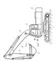
図1は本発明に係る油圧ショベルの第1実施形態を示す側面図、図2は図1に示す油圧ショベルの第1実施形態に備えられるバケットを示す斜視図、図3は図2に示すバケットにおいてアダプタから要部を構成する掘削爪を離脱させた状態を示す斜視図、図4は本発明に係る油圧ショベルの第1実施形態に備えられる電気制御系統を示すブロック図である。 1 is a side view showing a first embodiment of a hydraulic excavator according to the present invention, FIG. 2 is a perspective view showing a bucket provided in the first embodiment of the hydraulic excavator shown in FIG. 1, and FIG. 3 is a bucket shown in FIG. FIG. 4 is a perspective view showing a state in which excavation claws constituting the main part are detached from the adapter, and FIG. 4 is a block diagram showing an electric control system provided in the first embodiment of the hydraulic excavator according to the present invention.
本発明に係る油圧ショベルの第1実施形態は、図1に示すように、走行体1と、この走行体1上に配置され、運転室3を備えた旋回体2と、この旋回体2に上下方向の回動可能に連結されたブーム4と、このブーム4に上下方向の回動可能に連結されたアーム5と、このアーム5に回動可能に連結されたバケット6とを備えている。ブーム4、アーム5、及びバケット6によって土壌の掘削作業を行なうフロント作業機が構成されている。 As shown in FIG. 1, a first embodiment of a hydraulic excavator according to the present invention includes a traveling body 1, a revolving
この第1実施形態の要部を構成するバケット6は、図2,3に示すように、曲板から成る底板10と、この底板10の両側に取り付けられる側板11と、これらの側板11の前端部に固定される端板12と、これらの端板12の下端に固定されるサイドカッタ13と、底板10の前端部に設けられるカッティングプレート14と、底板10を補強するウェアプレート15とを備えている。 As shown in FIGS. 2 and 3, the
カッティングプレート14には、複数のアダプタ16を固定してある。これらのアダプタ16には、掘削作業に活用される掘削爪17を装着させてある。 A plurality of
この第1実施形態は特に、バケット6に、土壌へ高周波パルスを放射し、この土壌を通過した高周波パルスを受信する送受信部を備えている。この送受信部は、例えば複数のアダプタ16のうちの所定のアダプタ16aに装着され、高周波パルスを土壌へ放射する送信側掘削爪17aと、所定のアダプタ16aに隣接されるアダプタ16bに装着され、土壌を通過した高周波パルスを受信する受信側掘削爪17bとから成っている。 In the first embodiment, in particular, the
送信側掘削爪17a、受信側掘削爪17bのそれぞれは、図3に示すように、例えばアルミナ系の耐摩耗性を有する絶縁材から成る溶射部18を介してアダプタ16a,16bの該当するものに装着されている。 As shown in FIG. 3, each of the transmission-
これらの送信側掘削爪17a、受信側掘削爪17bは、ケーブル9を介して後述のコントローラ20に接続されている。すなわち、バケット6の送信側掘削爪17a、受信側掘削爪17bと後述のコントローラ20とは、図1に示すように、ブーム4及びアーム5に沿わせてバケット6まで延設させたケーブル9によって接続させてある。 These transmission-
上述のコントローラ20は、図4に示すように、送信側掘削爪17aに、土壌へ高周波パルスを放射させるための信号を出力する出力部20dと、土壌を通過した高周波パルスを受信した受信側掘削爪17bからの信号を入力する入力部20aと共に、演算部20bと記憶部20cを備えている。 As shown in FIG. 4, the
記憶部20cは、予め受信側掘削爪17bで受信される高周波パルスに相応する演算要素と、土壌の含水率との関係を記憶する。演算部20bは、受信側掘削爪17bで受信された高周波パルスに基づいて演算要素を求めると共に、この求めた演算要素と、記憶部20cに記憶された演算要素と土壌の含水率との関係から該当する土壌の含水率を演算する処理を行なう。 The memory |
図4に示すように、コントローラ20の入力部20aには、記憶部20cに記憶される演算要素と土壌の含水率との関係を設定する入力装置21を接続してある。また、コントローラ20の出力部20dには、演算部20bで求められた土壌の含水率を表示する表示装置22を接続してある。図1に示すように、コントローラ20と表示装置22とは、例えば運転室3内に配置してある。 As shown in FIG. 4, the
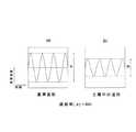
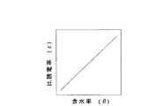
図5〜7は誘電率測定法であるADR方式の原理を説明する図で、図5の(a)図は基準波形を示す図、(b)図は土壌を通過した波形を示す図、図6は比誘電率と減衰率の関係を示す図、図7は含水率と比誘電率の関係を示す図である。 FIGS. 5 to 7 are diagrams for explaining the principle of the ADR method, which is a dielectric constant measurement method. FIG. 5A is a diagram showing a reference waveform, and FIG. 5B is a diagram showing a waveform passing through soil. 6 is a diagram showing the relationship between the relative permittivity and the attenuation factor, and FIG. 7 is a diagram showing the relationship between the moisture content and the relative permittivity.
この第1実施形態は例えば、土壌の締め固め作業に要する期間の予測のために行なわれる土壌の含水率の測定等に際して活用される。含水率の測定は例えば、土壌中の誘電率に依存する誘電率測定法である公知のADR(Amplitude Domain Reflectrometry)方式によって行なわれる。このADR方式について簡単に説明する。 This first embodiment is utilized, for example, when measuring the moisture content of soil, which is performed for the prediction of the period required for soil compaction work. The moisture content is measured, for example, by a known ADR (Amplitude Domain Reflectrometry) method, which is a dielectric constant measurement method depending on the dielectric constant in soil. This ADR method will be briefly described.
高周波パルスの送受信部が土壌中にないときに、受信部で受信される高周波パルスの基準波形の強度は、図5の(a)に示すように受信強度Aと比較的大きいが、土壌中を通過した後に受信部で受信される波形の強度は、受信強度Bと小さくなる。これらの受信強度A,Bから
減衰率(α)=B/A
が求められる。When the high-frequency pulse transmitting / receiving unit is not in the soil, the intensity of the reference waveform of the high-frequency pulse received by the receiving unit is relatively large as the reception intensity A as shown in FIG. The intensity of the waveform received by the receiving unit after passing through becomes smaller as the reception intensity B. From these reception strengths A and B
Attenuation rate (α) = B / A
Is required.
図6に示すように、比誘電率(ε)と減衰率(α)との間には相関関係があり、図7に示すように、含水率(θ)と比誘電率(ε)との間にも相関関係が存在する。これらの相関関係から、土壌の含水率(θ)は、受信部で受信される土壌中を通過した高周波パルスに基づいて求められる演算要素、例えば出力電圧(V)と相関関係を持つことが知られている。ADR方式は、含水率(θ)と、土壌を通過した高周波パルスに基づいて求められる出力電圧(V)との相関関係を利用して、土壌中の含水率(θ)を測定するものである。 As shown in FIG. 6, there is a correlation between the relative permittivity (ε) and the attenuation rate (α). As shown in FIG. 7, the moisture content (θ) and the relative permittivity (ε) There is also a correlation between them. From these correlations, it is known that the moisture content (θ) of the soil has a correlation with a calculation element obtained based on the high-frequency pulse passed through the soil received by the receiving unit, for example, the output voltage (V). It has been. The ADR method measures the moisture content (θ) in the soil by utilizing the correlation between the moisture content (θ) and the output voltage (V) obtained based on the high-frequency pulse that has passed through the soil. .
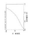
図8は本発明に係る油圧ショベルの第1実施形態に備えられるコントローラの記憶部に記憶される出力電圧と土壌の含水率の関係を示す図である。 FIG. 8 is a diagram showing the relationship between the output voltage stored in the storage unit of the controller provided in the first embodiment of the hydraulic excavator according to the present invention and the moisture content of the soil.
本発明の油圧ショベルの第1実施形態は、例えば或る領域内の複数箇所の土壌の含有率(θ)を測定しようとする場合、1箇所の土壌がサンプルとして採取され、そのサンプルによって、当該土壌の固有の「演算要素すなわち出力電圧(V)と含水率(θ)の関係」が周知のようにして求められる。図8は、このようにして求められた出力電圧(V)と含水率(θ)の関係の一例を示している。 In the first embodiment of the hydraulic excavator of the present invention, for example, when the content (θ) of a plurality of soils in a certain region is to be measured, one soil is collected as a sample, The unique “calculation element, that is, the relationship between the output voltage (V) and the moisture content (θ)” of the soil is determined in a known manner. FIG. 8 shows an example of the relationship between the output voltage (V) thus obtained and the moisture content (θ).
この図8に示す出力電圧(V)と含水率(θ)の関係が、図4に示す入力装置21によって入力され、コントローラ20の記憶部20cに予め記憶される。このような準備の後に、図1に示すこの第1実施形態の油圧ショベルを、他の測定対象の土壌の箇所まで移動させる。ここでブーム4等を駆動し、同図1に示すように、バケット6の刃先を所定の深さDまで土壌中に食い込ませる。 The relationship between the output voltage (V) and the water content (θ) shown in FIG. 8 is input by the
この状態において、コントローラ20の演算部20bからの指令により出力部20dからの信号を送信側掘削爪17aに出力する。これにより送信側掘削爪17aから高周波パルスが土壌中に放射される。土壌を通過した高周波パルスが受信側掘削爪17bで受信される。 In this state, a signal from the
受信側掘削爪17bからの信号がコントローラ20の入力部20aを介して演算部20bに入力され、ここで受信した高周波パルスに相応する出力電圧(V)が求められる。この求められた出力電圧(V)と、記憶部20cに記憶された図8に示す相関関係とから、測定した土壌の含水率(θ)が演算される。求められた含水率(θ)に相応する表示信号が、出力部20dを介して表示装置22に出力され、表示装置22に今測定した土壌の含水率(θ)がリアルタイムに表示される。 A signal from the receiving
このように構成した本発明の第1実施形態によれば、移動体であるこの油圧ショベルのバケット6に高周波パルスの送受信を行なう送受信部を構成する送信側掘削爪17a及び受信側掘削爪17bを備えたことから、高周波パルスの送受信部を移動させる台車等の移動体を別に要することがなく、比較的簡単な構成で土壌の含水率(θ)を計測することができる。これにより、この土壌の製作費を安く抑えられる。また、高周波パルスの送受信部が、バケット6の送信側掘削爪17aと受信側掘削爪17bとから成る簡単な構成であるので、この点でも製作費を安くすることに貢献する。 According to the first embodiment of the present invention configured as described above, the transmission-
また、コントローラ20と、送受信部を構成する送信側掘削爪17a及び受信側掘削爪17bとを接続するケーブル9を、ブーム4及びアーム5に沿わせてバケット6まで延設させた構成にしてあることから、ケーブル9を一定長とすることができ、測定される土壌の位置の如何に拘わらず長過ぎるケーブルによって過大な装備となることを防止できると共に、一定長さのケーブル9を介して土壌の含水率(θ)の測定を行なうので、測定誤差を小さく抑えることができ、含水率(θ)の高い測定精度を確保できる。 In addition, the
また、運転室3内に、コントローラ20の演算部20bで求められた土壌の含水率(θ)を表示する表示装置22を備えたことから、運転室3内のオペレータは測定対象の土壌の含水率(θ)を容易に把握することができる。 Further, since the operator's
また、当該油圧ショベルを所定の領域内において順次移動させて土壌の測定を行なうことにより、多数箇所の土壌の含水率(θ)を比較的短時間のうちに測定することができ、その所定の領域に係る二次元平面の含水率(θ)の分布を容易に作成することができる。 Further, by measuring the soil by sequentially moving the hydraulic excavator within a predetermined region, the moisture content (θ) of a large number of soils can be measured within a relatively short time. The distribution of the moisture content (θ) of the two-dimensional plane related to the region can be easily created.
図9は本発明に係る油圧ショベルの第2実施形態を示す側面図、図10は図9のA−A矢視拡大図、図11は図10のB−B断面図、図12は本発明に係る油圧ショベルの第2実施形態に備えられる電気制御系統を示すブロック図である。 9 is a side view showing a second embodiment of the hydraulic excavator according to the present invention, FIG. 10 is an enlarged view taken along the line AA in FIG. 9, FIG. 11 is a cross-sectional view along BB in FIG. 10, and FIG. It is a block diagram which shows the electric control system with which 2nd Embodiment of the hydraulic shovel which concerns on is equipped.
これらの図9〜12に示す油圧ショベルの第2実施形態は、高周波パルスの送受信部の構成だけを上述の油圧ショベルの第1実施形態と異ならせてある。この第2実施形態は、送受信部を、底板10及び側板11の少なくとも一方に、例えばアルミナ系の耐摩耗性を有する絶縁材からなる溶射材を介して装着され、コントローラ20とケーブル9を介して接続されるピンによって構成してある。 The second embodiment of the hydraulic excavator shown in FIGS. 9 to 12 is different from the first embodiment of the hydraulic excavator described above only in the configuration of the transmission / reception unit for high-frequency pulses. In the second embodiment, the transmitting / receiving unit is mounted on at least one of the
すなわち、図10,11に示すように、一方の側板11に一対の送信側ピン25,26を接続させてあり、他方の側板11にも送信側ピン25,26の該当するものに対向するように、一対の受信側ピン28,29を装着させてある。また、底板10に、送信側ピン27と受信側ピン30とを例えば30cmの間隔で装着させてある。これらの送信側ピン25,26,27、及び受信側ピン28,29,30は、例えば40mmの長さに設定してあり、それぞれケーブル9を介して図9に示すコントローラ20に接続させてある。コントローラ20を含むその他の構成は、上述した第1実施形態と同等である。 That is, as shown in FIGS. 10 and 11, a pair of transmission pins 25 and 26 are connected to one
このように構成した本発明の油圧ショベルの第2実施形態も、例えば上述のADR方式を利用して土壌の含水率(θ)を測定できる。すなわち、送信側ピン25,26,27から土壌へ放射された高周波パルスが受信側ピン28,29,30で受信され、これらの受信側ピン28,29,30で受信された高周波パルスに基づいて求められた演算要素、すなわち出力電圧(V)と、コントローラ20の記憶部20cに記憶された出力電圧(V)と土壌の含水率(θ)との関係とから、該当する測定対象の土壌の含有率(θ)を測定することができ、上述した第1実施形態と同等の作用効果が得られる。 The second embodiment of the hydraulic excavator of the present invention configured as described above can also measure the moisture content (θ) of the soil using, for example, the ADR method described above. That is, high-frequency pulses radiated from the transmission-side pins 25, 26, and 27 to the soil are received by the reception-side pins 28, 29, and 30, and based on the high-frequency pulses received by these reception-side pins 28, 29, and 30. From the calculated calculation element, that is, the output voltage (V), the relationship between the output voltage (V) stored in the
また特に、この第2実施形態では、送信側ピン25と受信側ピン28の組、送信側ピン26と受信側ピン29の組、及び送信側ピン27と受信側ピン30の組の3つの送受信部の組み合わせによって含水率(θ)を測定するようにしてあり、その3つの組の送受信部のそれぞれから求められる含水率(θ)の平均値を演算して当該土壌の含水率(θ)とすることもできる。これにより、さらに信頼性の高い含水率(θ)の測定を実現させることができる。 In particular, in the second embodiment, there are three transmission / reception units, that is, a group of the
また、上述した第1実施形態におけるのと同様に、高周波パルスの送受信部が、バケット6の側板11に装着させた送信側ピン25,26および受信側ピン28,29と、底板10に装着させた送信側ピン29及び受信側ピン30とから成る簡単な構成であるので、この点でも製作費を安くすることに貢献する。 Similarly to the first embodiment described above, the high-frequency pulse transmission / reception unit is attached to the transmission side pins 25 and 26 and the reception side pins 28 and 29 attached to the
なお、この第2実施形態では、底板10と側板11の双方に、送信側ピン25,26,27、受信側ピン28,29,30を設けたが、本発明はこれに限られず、底板10あるいは側板11の一方の側に、送信側ピンと受信側ピンを設けた構成にしてもよい。 In the second embodiment, the transmission side pins 25, 26, 27 and the reception side pins 28, 29, 30 are provided on both the
また、上述した各実施形態は、ADR方式を利用して土壌の含水率(θ)を測定するようにしたが、本発明は、ADR方式に代えて、送受信部で受信された土壌を通過した高周波パルスに基づく演算要素を、土壌を通過する高周波パルスの伝達時間とする周知のTDR(Time Domain Reflectrometry)方式を利用して、土壌の含水率(θ)を測定することも可能である。この場合には、例えばバケット6に高周波パルスの送信部と受信部を兼ね、土壌の含水率の測定時には当該土壌中に埋設された状態に保持される単に1本のピンを設けた構成とすることもできる。 Moreover, although each embodiment mentioned above was made to measure the moisture content ((theta)) of a soil using an ADR system, it replaced with the ADR system and this invention passed the soil received by the transmission / reception part. It is also possible to measure the moisture content (θ) of the soil by using a well-known TDR (Time Domain Reflectrometry) method in which the calculation element based on the high frequency pulse is a transmission time of the high frequency pulse passing through the soil. In this case, for example, the
2 旋回体
3 運転室
4 ブーム
5 アーム
6 バケット
9 ケーブル
10 底板
11 側板
16a 所定のアダプタ
16b 隣接されるアダプタ
17a 送信側掘削爪
17b 受信側掘削爪
18 溶射部
20 コントローラ
20b 演算部
20c 記憶部
21 入力装置
22 表示装置
25 送信側ピン
26 送信側ピン
27 送信側ピン
28 受信側ピン
29 受信側ピン
30 受信側ピンDESCRIPTION OF
Claims (5)
Translated fromJapanese上記バケットに、上記土壌へ高周波パルスを放射し、この土壌を通過した高周波パルスを受信する送受信部を備えると共に、
予め設定される上記送受信部で受信される高周波パルスに相応する演算要素と、上記土壌の含水率との関係を記憶する記憶部と、
上記送受信部で受信された上記高周波パルスに基づいて上記演算要素を求め、この求めた演算要素と、上記記憶部に記憶された上記演算要素と上記土壌の含水率との関係とから該当する土壌の含水率を演算する演算部とを有するコントローラを備え、
このコントローラの上記記憶部に記憶される上記演算要素と土壌の含水率との関係を設定する入力装置を設けたことを特徴とする油圧ショベル。In excavators with buckets for excavating soil,
The bucket has a transmission / reception unit that radiates high-frequency pulses to the soil and receives the high-frequency pulses that have passed through the soil,
A calculation unit corresponding to the high-frequency pulse received by the transmitter / receiver set in advance, and a storage unit for storing the relationship between the moisture content of the soil,
The calculation element is obtained based on the high-frequency pulse received by the transmission / reception unit, and the corresponding soil from the calculated calculation element and the relationship between the calculation element stored in the storage unit and the moisture content of the soil A controller having a calculation unit for calculating the moisture content of
A hydraulic excavator comprising an input device for setting a relationship between the arithmetic element stored in the storage unit of the controller and the moisture content of soil.
上記送受信部が、上記バケットの複数のアダプタのうちの所定のアダプタに装着され、上記高周波パルスを上記土壌へ放射する送信側掘削爪と、上記所定のアダプタに隣接されるアダプタに装着され、上記土壌を通過した高周波パルスを受信する受信側掘削爪とから成り、
上記送信側掘削爪、及び上記受信側掘削爪を、上記所定のアダプタに絶縁材から成る溶射部を介して装着すると共に、ケーブルを介して上記コントローラに接続させたことを特徴とする油圧ショベル。In the hydraulic excavator according to claim 1,
The transmission / reception unit is attached to a predetermined adapter among the plurality of adapters of the bucket, is attached to a transmission side excavation claw that radiates the high-frequency pulse to the soil, and an adapter adjacent to the predetermined adapter, It consists of a receiving excavation claw that receives high-frequency pulses that have passed through the soil,
A hydraulic excavator, wherein the transmission side claw and the reception side claw are attached to the predetermined adapter via a thermal spraying portion made of an insulating material and connected to the controller via a cable.
上記送受信部が、上記バケットの底板及び側板の少なくとも一方に備えられ、上記高周波パルスを上記土壌へ放射する送信側ピンと、上記土壌を通過した高周波パルスを受信する受信側ピンとから成り、
上記送信側ピン、及び上記受信側ピンを、上記底板及び上記側板の少なくとも一方に絶縁材から成る溶射部を介して装着すると共に、ケーブルを介して上記コントローラに接続させたことを特徴とする油圧ショベル。In the hydraulic excavator according to claim 1,
The transmission / reception unit is provided on at least one of a bottom plate and a side plate of the bucket, and includes a transmission-side pin that radiates the high-frequency pulse to the soil, and a reception-side pin that receives the high-frequency pulse that has passed through the soil,
The transmission side pin and the reception side pin are attached to at least one of the bottom plate and the side plate via a thermal spraying part made of an insulating material, and are connected to the controller via a cable. Excavator.
上記コントローラを運転室内に配置すると共に、このコントローラと上記送受信部とを接続するケーブルを、ブーム及びアームに沿わせて上記バケットまで延設させたことを特徴とする油圧ショベル。The hydraulic excavator according to claim 1,
A hydraulic excavator, wherein the controller is disposed in a cab and a cable connecting the controller and the transmission / reception unit is extended to the bucket along a boom and an arm.
上記コントローラから出力される信号に応じて上記演算部で求められた土壌の含水率を表示する表示装置を備え、この表示装置を運転室内に配置したことを特徴とする油圧ショベル。The hydraulic excavator according to claim 1,
A hydraulic excavator comprising a display device that displays the moisture content of the soil determined by the calculation unit in response to a signal output from the controller, and the display device is disposed in a cab.
Priority Applications (1)
| Application Number | Priority Date | Filing Date | Title |
|---|---|---|---|
| JP2005017159AJP2006208046A (en) | 2005-01-25 | 2005-01-25 | Hydraulic shovel |
Applications Claiming Priority (1)
| Application Number | Priority Date | Filing Date | Title |
|---|---|---|---|
| JP2005017159AJP2006208046A (en) | 2005-01-25 | 2005-01-25 | Hydraulic shovel |
Publications (1)
| Publication Number | Publication Date |
|---|---|
| JP2006208046Atrue JP2006208046A (en) | 2006-08-10 |
Family
ID=36965090
Family Applications (1)
| Application Number | Title | Priority Date | Filing Date |
|---|---|---|---|
| JP2005017159APendingJP2006208046A (en) | 2005-01-25 | 2005-01-25 | Hydraulic shovel |
Country Status (1)
| Country | Link |
|---|---|
| JP (1) | JP2006208046A (en) |
Cited By (3)
| Publication number | Priority date | Publication date | Assignee | Title |
|---|---|---|---|---|
| JP2008096287A (en)* | 2006-10-12 | 2008-04-24 | Nobuyuki Suzuki | Wireless type soil humidity measurement instrument and automatic water supply device for plants |
| CN113026839A (en)* | 2015-08-24 | 2021-06-25 | 株式会社小松制作所 | Wheel loaders |
| AU2021203036B2 (en)* | 2013-11-25 | 2023-05-11 | Esco Group Llc | Wear part monitoring |
- 2005
- 2005-01-25JPJP2005017159Apatent/JP2006208046A/enactivePending
Cited By (6)
| Publication number | Priority date | Publication date | Assignee | Title |
|---|---|---|---|---|
| JP2008096287A (en)* | 2006-10-12 | 2008-04-24 | Nobuyuki Suzuki | Wireless type soil humidity measurement instrument and automatic water supply device for plants |
| AU2021203036B2 (en)* | 2013-11-25 | 2023-05-11 | Esco Group Llc | Wear part monitoring |
| AU2021203036B9 (en)* | 2013-11-25 | 2024-02-29 | Esco Group Llc | Wear part monitoring |
| AU2021203036A9 (en)* | 2013-11-25 | 2024-02-29 | Esco Group Llc | Wear part monitoring |
| AU2023202466B2 (en)* | 2013-11-25 | 2024-12-19 | Esco Group Llc | Wear part monitoring |
| CN113026839A (en)* | 2015-08-24 | 2021-06-25 | 株式会社小松制作所 | Wheel loaders |
Similar Documents
| Publication | Publication Date | Title |
|---|---|---|
| AU2016354542B2 (en) | Methods and systems for detecting heavy machine wear | |
| JP4286539B2 (en) | Method and apparatus for determining the position of an object in the ground during excavation work | |
| AU2015206035B2 (en) | Mine control system | |
| KR101713457B1 (en) | Construction management device for excavating equipment, construction management device for hydraulic shovel, excavating equipment, and construction management system | |
| US8311738B2 (en) | Boom-mounted machine locating system | |
| AU2010275283B2 (en) | Method and system for detecting the proximity of a conductive, buried structures | |
| CN102918210B (en) | Positioning devices and similar equipment for excavation | |
| CA2916434C (en) | Arrangement for controlling automated operation mode | |
| JP6699135B2 (en) | Electric resistivity detector and quality control method for soil cement body | |
| CN108387641A (en) | The wear-out life of ultrasonic sensing ground engagement tool | |
| US20180127952A1 (en) | Excavator bucket with integrated radar system | |
| EP3094807B1 (en) | Mine control system | |
| JP2006208046A (en) | Hydraulic shovel | |
| AU2014301655A1 (en) | Arrangement for controlling automated drilling operation mode | |
| CN113867198A (en) | Control system, method and device of tunneling equipment | |
| JP6994431B2 (en) | Metal exploration system and metal exploration method | |
| KR200194862Y1 (en) | Uniformity detection apparatus for the survey of buried structures by used gpr system | |
| JPH11109046A (en) | Excavated soil volume measurement system and method in shield method, and excavation control system and method using these | |
| JP2857781B2 (en) | Road surface cutter | |
| KR200194861Y1 (en) | Receive signal analysis device of detection apparatus for the survey of buried structures by used gpr system | |
| US20230296755A1 (en) | System and method for avoiding utility strikes by construction equipment | |
| KR200194863Y1 (en) | Detection apparatus for the survey of buried structures having receive signal saved device by used gpr system | |
| KR100250676B1 (en) | An excavating depth measurement device of an excavator | |
| JPH04285886A (en) | Snow thickness management and maintenance equipment | |
| JPH06307189A (en) | How to measure the propulsion depth of an underground propulsion unit |