JP2006204758A - Robot vacuum cleaner - Google Patents
Robot vacuum cleanerDownload PDFInfo
- Publication number
- JP2006204758A JP2006204758AJP2005023871AJP2005023871AJP2006204758AJP 2006204758 AJP2006204758 AJP 2006204758AJP 2005023871 AJP2005023871 AJP 2005023871AJP 2005023871 AJP2005023871 AJP 2005023871AJP 2006204758 AJP2006204758 AJP 2006204758A
- Authority
- JP
- Japan
- Prior art keywords
- charging
- electrode
- cleaner body
- charging stand
- vacuum cleaner
- Prior art date
- Legal status (The legal status is an assumption and is not a legal conclusion. Google has not performed a legal analysis and makes no representation as to the accuracy of the status listed.)
- Withdrawn
Links
Images


Landscapes
- Electric Suction Cleaners (AREA)
- Electric Vacuum Cleaner (AREA)
Abstract
Translated fromJapaneseDescription
Translated fromJapanese本発明は、二次電池を搭載して自立走行により清掃作業を行う掃除機本体が、充電装置に移動して充電を行うロボット掃除機に関する。 The present invention relates to a robot cleaner in which a main body of a cleaner that carries a cleaning operation by self-running with a secondary battery moves to a charging device and performs charging.
従来のロボット掃除機は、掃除機本体に吸込口(注入口)、電動送風機(真空モータ)、集塵室(汚物貯蔵室)、走行制御部(マイコン)、バッテリー(二次電池)、駆動ローラを備え、バッテリーに対する充電装置は、床面からの上り斜面とこれに連続した水平方向の平坦面を有する床パネルの端部に、垂直方向の側壁部を設けた自動電源充電手段を備えたものがある。これらの自動電源充電手段と掃除機本体とには、それぞれ直流電源注入用プラグおよび充電用コンセントが設けられている。 A conventional robot cleaner has a suction port (injection port), an electric blower (vacuum motor), a dust collection chamber (dirt storage chamber), a travel control unit (microcomputer), a battery (secondary battery), and a drive roller. The charging device for the battery is provided with an automatic power charging means provided with a vertical side wall at the end of the floor panel having an ascending slope from the floor and a horizontal flat surface continuous thereto. There is. These automatic power supply charging means and the cleaner body are provided with a DC power supply plug and a charging outlet, respectively.
そして、バッテリーへの充電時には、掃除機本体に有する駆動ローラを回転させて床パネルの上面まで移動させ、掃除機本体の充電用コンセントを自動電源充電手段の直流電源注入用プラグに近接するとともに、床パネルに設けた係止片により駆動ローラをロックして自動電源充電手段とロボット掃除機との離反を阻止している。この状態でソレノイドを動作させることにより直流電源注入用プラグを前進させ、充電用コンセントの導電体に挿入して導通接続させ、自動電源充電手段から電気をバッテリーに供給して充電することを可能にしている。(例えば、特許文献1参照) And when charging the battery, rotate the drive roller in the vacuum cleaner body and move it to the upper surface of the floor panel, close the charging outlet of the vacuum cleaner body to the DC power injection plug of the automatic power charging means, The driving roller is locked by a locking piece provided on the floor panel to prevent the automatic power supply charging means from separating from the robot cleaner. By operating the solenoid in this state, the plug for injecting the DC power supply is advanced, inserted into the conductor of the charging outlet and electrically connected, and it is possible to supply electricity from the automatic power supply charging means to the battery for charging. ing. (For example, see Patent Document 1)
また、他の従来の電気掃除機用充電台は、断面がかまぼこ形の傾斜面を有する凸部と、この凸部の後方の隣接部に車が落ち込み可能な凹部とを有し、この凹部の上方には一対の端子板が備けられている。一方据え置き充電式掃除機は、掃除機本体の本体ケースの下方に有する吸込部の前後部にそれぞれ移動用の車を設け、この後部にある車の上方には、前記充電台の端子板に接触可能な一対の端子板が設けられている。 In addition, another conventional charging base for a vacuum cleaner has a convex portion having an inclined surface with a semi-cylindrical cross section, and a concave portion in which a car can fall into an adjacent portion behind the convex portion. A pair of terminal boards is provided above. On the other hand, the stationary rechargeable vacuum cleaner is provided with a moving car at the front and rear of the suction part below the main body case of the vacuum cleaner body, and above the car at the rear is in contact with the terminal board of the charging stand. A possible pair of terminal boards is provided.
そして、この据え置き充電式掃除機に充電する場合には、作業者が充電台に向かって掃除機本体の吸込部を移動させ、吸込部にある後部の車が、傾斜面を有する凸部を乗り越えて掃除機本体の自重により凹部に落ち込んだ位置で固定されることにより、それぞれ一対の前記端子板が導通接続され、充電が可能となっている。また、充電後に掃除機本体を充電台から離脱させる場合には、作業者が掃除機本体を後方に移動させることにより、後部の車の上方にある本体ケースおよび充電台の接触部を支点として吸込部が回動し、後部の車を凹部から上方に引き上げて切り離すことが可能となっている。(例えば、特許文献2参照)
従来のこれらの充電式電気掃除機は、前者の場合、直流電源注入用プラグと充電用コンセントとの近接状態、および両者の電気的な導通状態を確実に維持するためには、駆動ローラをロックする係止片、および直流電源注入用プラグを充電用コンセントに向かって押し出すためのソレノイドが必要となっていた。また、後者の場合、作業者が掃除機本体を充電台に向かって移動させる必要があるとともに、吸込部に設けた後部の車が充電台の凹部に落ち込むことにより位置が固定された状態であっても、充電台の端子板または掃除機本体の端子板が変形、あるいはそのバネ性能が低下した際は、充電開始時または充電中に両者の電気的な導通状態を確実にすることが困難であった。 These conventional rechargeable vacuum cleaners, in the former case, lock the drive roller in order to reliably maintain the proximity of the DC power injection plug and the charging outlet and the electrical conduction between them. And a solenoid for pushing the plug for direct current power supply injection toward the charging outlet. In the latter case, the operator needs to move the cleaner body toward the charging stand, and the position of the rear car provided in the suction portion is fixed by dropping into the recess of the charging stand. However, when the terminal board of the charging base or the terminal board of the vacuum cleaner body is deformed or its spring performance is reduced, it is difficult to ensure the electrical continuity between the two at the start of charging or during charging. there were.
本発明は、上記事情によりなされたものであって、充電時における掃除機本体と充電装置との電気的な導通状態を確実にするロボット掃除機の提供を目的とする。 This invention is made | formed by the said situation, Comprising: It aims at provision of the robot cleaner which ensures the electrical continuity state of the cleaner body and charging device at the time of charge.
本発明は、電動送風機、集塵室、気体の吸込口および排気口、走行制御部、走行用車輪、二次電池を設けて自立走行が可能な掃除機本体と、この掃除機本体の外周部に設けられ前記二次電池に導通された充電用電極と、床面から連続する上り斜面およびこの上り斜面から連続する下り斜面を有する充電台と、この充電台の前記下り斜面の下端部に近接する充電スタンドと、この充電スタンドに設けられ前記充電用電極に接触可能な位置に配置した出力用電極と、この出力用電極に電力を供給する電力供給装置とを備え、前記二次電池の充電時は、前記掃除機本体が前記走行用車輪により前記上り斜面を乗り越えて、前記下り斜面の位置で重力により前記充電用電極を前記出力用電極に常時圧接するようにしたロボット掃除機であることを特徴とする。 The present invention provides an electric blower, a dust collection chamber, a gas suction port and an exhaust port, a travel control unit, a travel wheel, a secondary battery, and a vacuum cleaner body capable of running independently, and an outer peripheral portion of the vacuum cleaner body A charging electrode provided on the secondary battery and connected to the secondary battery; a charging base having an upslope continuous from the floor and a downslope continuous from the upslope; and a lower end of the downslope of the charging base A charging station, an output electrode provided on the charging station and disposed at a position where the charging electrode can contact the charging electrode, and a power supply device that supplies power to the output electrode, and charging the secondary battery The robot cleaner is configured such that the main body of the cleaner passes over the ascending slope by the traveling wheel, and the charging electrode is always pressed against the output electrode by gravity at the position of the descending slope. Features To.
本発明のロボット掃除機は、掃除機本体と充電装置との充電時における電気的な導通状態を確実にすることができる。 The robot cleaner of the present invention can ensure the electrical continuity when the cleaner body and the charging device are charged.
以下、本発明によるロボット掃除機の実施態様について、図1から図6を参照して説明する。 Hereinafter, embodiments of the robot cleaner according to the present invention will be described with reference to FIGS. 1 to 6.
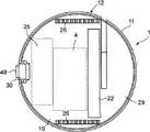
図1および図3は、この発明のロボット掃除機1の掃除機本体3を示し、この掃除機本体3は、一般に住居内の被清掃面である床面上を自立走行して清掃作業を行う。そして、この掃除機本体3には、清掃室内の自立走行および清掃作業を行うために、その動力源となる電力を蓄えた二次電池としてのバッテリー4が搭載されている。このバッテリー4は、掃除機本体3が設置された室内の清掃作業を終了した後に、図1に示すように、充電装置5の一部を構成する充電台6の上面まで掃除機本体3が自動的に移動して、充電スタンド7から電気の提供を受けて充電されるようになっている。 1 and 3 show a cleaner body 3 of a
掃除機本体3は、ほぼ円形平板状を有する底板部10の外周縁に、上面が閉鎖されたほぼ円筒状の上部ケース11の下端縁が嵌合したケース本体12により外観を形成している。このケース本体12の内部は、中間部を機密状態で区画した仕切板13が設けられ、その上面には、モータ部14およびその前部に一体的に配置されたファン部15により構成された電動送風機16が固定されている。この電動送風機16の前方には、気体のろ過作用を有する集塵部となる集塵体収容部17が設けられ、この集塵体収容部17には、ケース本体12の外方から挿脱可能となった図示しない集塵カップが収容されている。また、電動送風機16の後方には、排気風路18を介して、上部ケース11の壁面に設けられた多数のスリットからなる排気口19が設けられている。また、上部ケース11の上面には、図示しない電源スイッチや制御ボタンを有する操作パネル20が設けられている。 The vacuum cleaner main body 3 has an appearance formed by a case
仕切板13の下方には、その上端部が集塵体収容部17に連通する連結管21が設けられ、この連結管21の下端部には、前記底板部10から多少下方に突出した本体吸込口22が設けられている。本体吸込口22は、図2にも示されるように、掃除機本体3の左右方向に細長い矩形となって開口している。また、連結管21の後方には、直方体の形状をした二次電池である前記バッテリー4が底板部10に固定されている。 Below the
そして、ケース本体12の左右には、外周面に多数の凹凸が形成された一対の走行用車輪26が、それぞれ回転可能に軸支されている。この走行用車輪26は、本体ケース12に収容されて図4に示した車輪モータ27により駆動されるとともに、走行制御部25により制御されて、磁気クラッチ28により正回転、逆回転および停止が、左右独立してそれぞれ可能となっている。また、ケース本体12の後端下部中央には円筒状をした一個の後輪30が回転自在に軸支されている。さらに、本体ケース12の前部下方には、傾斜面29が設けられドアーレールなどの障害物を容易に乗り越えることができるようになっている。 A pair of traveling
また、後輪30の上側には、電極収容室33が設けられ、二次電池であるバッテリー4に電気的に導通されたリード線34が引き込まれている。このリード線34には、図5に示すように円板状のストッパー35が固定された円柱状の支持棒36が接続されており、この支持棒36は、上部ケース11に有するガイド壁37の貫通孔38にスライド可能に支持され、その先端に充電用電極40が固定されている。この充電用電極40とガイド壁37との間には、圧縮されたコイルスプリング41が配置され、これによりストッパー35がガイド壁37に当接するまでの範囲で、充電用電極40が段発的に外方に出没可能となっている。これらのリード線34、ストッパー35、支持棒36、ガイド壁37の貫通孔38、充電用電極40は、それぞれ一対ずつ電極収容室33に収容されている。 In addition, an
そして、上部ケース11の前部半周分の周囲には、図4に示すように、本体ケース12の周囲の状況を検知する複数個の周囲センサー45、また上部ケース11の前部の上側には、掃除機本体3の進行方向にある障害物などの高さを検知する高さセンサー46、さらに、前記傾斜面29の上部には、前方の段差などの高さを検知する段差センサー47、また上部ケース11の後側下方には、後述する充電台40を検知する充電台センサー48がそれぞれ設けられている。これらのセンサーは、赤外線センサーあるいは画像センサーなどの非接触型のセンサーからなり、本体ケース12に内蔵の前記走行制御部25に記憶された走行プログラムおよび充電プログラムにより制御される。 As shown in FIG. 4, a plurality of surrounding
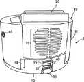
前述した充電装置5は、図6に示すように、清掃を必要とする室内の片隅に配置された充電台6、およびこの充電台6の端部に結合された充電スタンド7から構成されている。充電台6は、その下面49が水平方向の平坦面となって被清掃面等の床面に面接触し、上面は床面に連続する緩やかな上り斜面50とこの上端に連続する下り斜面51とを有している。充電スタンド7は、下り斜面51の下端部に結合され、ほぼ円筒状となった本体ケース12の外周面とほぼ同一の曲面を有する嵌合壁53、および充電制御回路を収容した電力供給装置54、および前記充電台センサー48が検知する被検知穴52が設けられている。また、電力供給装置54からは、その充電制御回路に一端が接続され、他端が商用電源のコンセントに差し込むプラグ55が接続されたコード60が外方に延びている。 As shown in FIG. 6, the above-described charging device 5 includes a
充電スタンド7の嵌合壁53の中心部には、電極開口56が設けられ、この電極開口56からは、一対の前記充電用電極40に接触可能な位置に配置した一対の出力用電極57がそれぞれ突出している。これらの出力用電極57は、図5に示した充電用電極40と同様な取り付け構造で段発的に出没可能となって、リード線58により電力供給装置54の充電制御回路に導通接続されている。 An
次に、これらの構成からなるロボット掃除機1による清掃動作について説明する。このロボット掃除機1が設置された室内において、まず、操作者により掃除機本体3の操作パネル20に設けた電源スイッチおよび清掃開始ボタンをオンさせるか、または予め設定された時刻になると、走行制御部25に記憶された走行プログラムにしたがって、車輪モータ27の駆動を開始するとともに磁気クラッチ28を制御して走行用車輪26を正転させる。これにより掃除機本体3は、充電スタンド7から離反するように充電台6の下り斜面51を逆方向に上ることによって、充電スタンド7に設けられた出力用電極57と掃除機本体3の充電用電極40との接触が解かれる。そして走行用車輪26によって下り斜面51を上りきって、さらに上り斜面50を下って行って充電台6から室内の床面に達すると、次に掃除機本体3に設けた複数の周囲センサー45により検知しながら、予め定められた被清掃面のスタート地点に向かって自動走行していく。 Next, the cleaning operation by the
そして、掃除機本体3が所定のスタート地点である被清掃面に到着したときに、電動送風機16のモータ部14の駆動を開始することによりファン部15が回転し、本体吸込口22から被清掃面上の空気および塵埃の吸引を開始する。次に掃除機本体3は、周辺センサー45、高さセンサー46、段差センサー47により検知しながら予め走行プログラムで設定された被清掃面上の走行軌道を自動走行して行って、その清掃範囲を広げていく。この間に、本体吸込口22から吸引されて連結管21を経由した空気および塵埃のうち、集塵室である集塵体収容部17で捕捉された塵埃は集塵カップに収容され、ろ過された空気は電動送風機16を通過して、排気風路18を経由し排気口19から掃除機本体3の外方に放出される。 When the cleaner body 3 arrives at the surface to be cleaned, which is a predetermined start point, the
このようにして所定の被清掃面の走行清掃が完了した場合には、電動送風機16の駆動を停止するとともに、掃除機本体3は、走行用車輪26によって充電装置5に向かって自動走行して行く。そして、充電台6の近くに達して充電台センサー48が被検知穴52を検知すると、掃除機本体3は180度の角度に反転し、後輪30および排気口19を前にして、充電台6の上り傾斜50を上り、下り斜面51を下っていく。そして、掃除機本体3の充電台センサー48が被検知穴52に近接すると、走行プログラムに従って車輪モータ27に対する電力供給を中止する。 When the traveling cleaning of the predetermined surface to be cleaned is completed in this way, the driving of the
これにより、掃除機本体3の自重の影響を受けて、走行用車輪26が自由回転して下り斜面51を少し下ることで、掃除機本体3から外方に多少突出している一対の充電用電極40は、充電スタンド7に設けられた一対の出力用電極57に接触する。このとき、充電スタンド7の嵌合壁53は、掃除機本体3の本体ケース12の外周面とほぼ同一の曲面を有するために、充電用電極40と出力用電極57との接触をより円滑に行うことできる。 Thereby, under the influence of the dead weight of the cleaner body 3, the pair of charging electrodes slightly protrude outward from the cleaner body 3 by the traveling
この充電用電極40と出力用電極57との接触が行われたことを、電力供給装置54の充電制御回路が判断して電力の供給を開始する。これにより充電装置5から掃除機本体3の二次電池であるバッテリー4に充電が行われ、次の清掃行動に備える。この充電中は、掃除機本体3の自重が作用して、充電台6の下り斜面51に対して走行用車輪26が下方に向かって回転しようとするために、出力用電極57に対し充電用電極40が常に押し付けられて、両者の接触が確実に行われる。これらの充電用電極40と出力用電極57との接触は、コイルスプリング41により段発的に行われることにより、両者が接触する際の衝撃や騒音の発生防止、および接触状態の継続性を増すことができる。 The charging control circuit of the
なお、このコイルスプリング41に代わって、板スプリングでも良いし、またこれらのスプリングを設けなかった場合でも、充電用電極40と出力用電極57との接触が不可能になることはない。また、上記実施例においては、充電台6の端部に充電スタンド7を結合したが、この充電スタンド7は、充電台6に有する下り斜面51の下端部近くに多少離れて配置しても良く、これらの両者を必ずしも結合する必要のないものである。 In place of the
以上説明したように、本発明は上記実施の形態に限定されるものではなく、その趣旨を逸脱しない範囲で変形することが可能である。 As described above, the present invention is not limited to the above embodiment, and can be modified without departing from the spirit of the present invention.
1 ロボット掃除機
3 掃除機本体
4 二次電池(バッテリー)
6 充電台
7 充電スタンド(充電装置)
16 電動送風機
17 集塵室(集塵体収容部)
19 排気口
25 走行制御部
26 走行用車輪
50 上り斜面
51 下り斜面
54 電力供給装置(充電装置)
57 出力用電極(充電装置)1 Robot vacuum cleaner 3 Vacuum
6 Charging stand 7 Charging stand (charging device)
16 Electric blower 17 Dust collection chamber (dust collector housing)
19
57 Output electrode (charging device)
Claims (2)
Translated fromJapaneseこの掃除機本体の外周部に設けられ前記二次電池に導通された充電用電極と、
床面から連続する上り斜面およびこの上り斜面から連続する下り斜面を有する充電台と、
この充電台の前記下り斜面の下端部に近接する充電スタンドと、
この充電スタンドに設けられ前記充電用電極に接触可能な位置に配置した出力用電極と、
この出力用電極に電力を供給する電力供給装置とを備え、
前記二次電池の充電時は、前記掃除機本体が前記走行用車輪により前記上り斜面を乗り越えて、前記下り斜面の位置で重力により前記充電用電極を前記出力用電極に常時圧接するようにしたことを特徴とするロボット掃除機。An electric blower, a dust collection chamber, a gas suction port and an exhaust port, a traveling control unit, a traveling wheel, a vacuum cleaner body capable of running independently by providing a secondary battery;
A charging electrode provided on the outer periphery of the vacuum cleaner body and conducted to the secondary battery;
A charging stand having an upward slope continuous from the floor and a downward slope continuous from the upward slope;
A charging stand close to the lower end of the downward slope of the charging stand;
An output electrode disposed in a position where the charging stand is in contact with the charging electrode; and
A power supply device for supplying power to the output electrode;
When charging the secondary battery, the main body of the vacuum cleaner gets over the up slope by the traveling wheel, and the charging electrode is always pressed against the output electrode by gravity at the position of the down slope. Robot cleaner characterized by that.
Priority Applications (1)
| Application Number | Priority Date | Filing Date | Title |
|---|---|---|---|
| JP2005023871AJP2006204758A (en) | 2005-01-31 | 2005-01-31 | Robot vacuum cleaner |
Applications Claiming Priority (1)
| Application Number | Priority Date | Filing Date | Title |
|---|---|---|---|
| JP2005023871AJP2006204758A (en) | 2005-01-31 | 2005-01-31 | Robot vacuum cleaner |
Publications (1)
| Publication Number | Publication Date |
|---|---|
| JP2006204758Atrue JP2006204758A (en) | 2006-08-10 |
Family
ID=36962187
Family Applications (1)
| Application Number | Title | Priority Date | Filing Date |
|---|---|---|---|
| JP2005023871AWithdrawnJP2006204758A (en) | 2005-01-31 | 2005-01-31 | Robot vacuum cleaner |
Country Status (1)
| Country | Link |
|---|---|
| JP (1) | JP2006204758A (en) |
Cited By (18)
| Publication number | Priority date | Publication date | Assignee | Title |
|---|---|---|---|---|
| KR101123185B1 (en)* | 2009-03-18 | 2012-03-19 | 에이스전자(주) | Robot cleaner |
| KR101123186B1 (en)* | 2009-03-18 | 2012-03-20 | 에이스전자(주) | Robot cleaner |
| WO2013046994A1 (en)* | 2011-09-29 | 2013-04-04 | シャープ株式会社 | Cleaning robot |
| WO2013047073A1 (en)* | 2011-09-29 | 2013-04-04 | シャープ株式会社 | Cleaning robot |
| JP2013070952A (en)* | 2011-09-29 | 2013-04-22 | Sharp Corp | Cleaning robot |
| JP2013070951A (en)* | 2011-09-29 | 2013-04-22 | Sharp Corp | Cleaning robot |
| JP2013075175A (en)* | 2012-12-04 | 2013-04-25 | Sharp Corp | Cleaning robot |
| WO2014094834A1 (en)* | 2012-12-18 | 2014-06-26 | Alfred Kärcher Gmbh & Co. Kg | Self-propelled and self-steering floor cleaning device |
| JP2015198925A (en)* | 2014-04-09 | 2015-11-12 | 燕成祥 | Inductive cleaning equipment and induction cleaning kit |
| JP2017012907A (en)* | 2016-10-26 | 2017-01-19 | シャープ株式会社 | Cleaning robot |
| CN107713920A (en)* | 2017-09-25 | 2018-02-23 | 北京石头世纪科技有限公司 | Method for automatically cleaning device and charging same |
| CN109391014A (en)* | 2018-12-20 | 2019-02-26 | 福建(泉州)哈工大工程技术研究院 | A kind of mobile robot recharging device |
| WO2020116412A1 (en)* | 2018-12-03 | 2020-06-11 | Groove X株式会社 | Charging station for robot |
| WO2021020671A1 (en)* | 2019-07-31 | 2021-02-04 | 엘지전자 주식회사 | Charging stand for moving robot |
| KR20210015596A (en)* | 2019-07-31 | 2021-02-10 | 엘지전자 주식회사 | Charging apparatus for the moving robot |
| CN114513033A (en)* | 2022-03-04 | 2022-05-17 | 珠海市一微机器人技术有限公司 | Magnetic charging robot seat withdrawing method, chip and robot |
| JP2022161975A (en)* | 2018-09-18 | 2022-10-21 | パナソニックIpマネジメント株式会社 | self-propelled vacuum cleaner |
| US11910991B2 (en) | 2019-07-31 | 2024-02-27 | Lg Electronics Inc. | Charging apparatus for mobile robot |
- 2005
- 2005-01-31JPJP2005023871Apatent/JP2006204758A/ennot_activeWithdrawn
Cited By (34)
| Publication number | Priority date | Publication date | Assignee | Title |
|---|---|---|---|---|
| KR101123185B1 (en)* | 2009-03-18 | 2012-03-19 | 에이스전자(주) | Robot cleaner |
| KR101123186B1 (en)* | 2009-03-18 | 2012-03-20 | 에이스전자(주) | Robot cleaner |
| JP2013070950A (en)* | 2011-09-29 | 2013-04-22 | Sharp Corp | Cleaning robot |
| WO2013047073A1 (en)* | 2011-09-29 | 2013-04-04 | シャープ株式会社 | Cleaning robot |
| JP2013070952A (en)* | 2011-09-29 | 2013-04-22 | Sharp Corp | Cleaning robot |
| JP2013070951A (en)* | 2011-09-29 | 2013-04-22 | Sharp Corp | Cleaning robot |
| WO2013046994A1 (en)* | 2011-09-29 | 2013-04-04 | シャープ株式会社 | Cleaning robot |
| JP2013075175A (en)* | 2012-12-04 | 2013-04-25 | Sharp Corp | Cleaning robot |
| WO2014094834A1 (en)* | 2012-12-18 | 2014-06-26 | Alfred Kärcher Gmbh & Co. Kg | Self-propelled and self-steering floor cleaning device |
| JP2015198925A (en)* | 2014-04-09 | 2015-11-12 | 燕成祥 | Inductive cleaning equipment and induction cleaning kit |
| JP2017012907A (en)* | 2016-10-26 | 2017-01-19 | シャープ株式会社 | Cleaning robot |
| CN107713920A (en)* | 2017-09-25 | 2018-02-23 | 北京石头世纪科技有限公司 | Method for automatically cleaning device and charging same |
| CN107713920B (en)* | 2017-09-25 | 2022-06-03 | 北京石头创新科技有限公司 | Automatic cleaning device and method for charging the same |
| JP7429873B2 (en) | 2018-09-18 | 2024-02-09 | パナソニックIpマネジメント株式会社 | self-propelled vacuum cleaner |
| JP2022161975A (en)* | 2018-09-18 | 2022-10-21 | パナソニックIpマネジメント株式会社 | self-propelled vacuum cleaner |
| CN113165162A (en)* | 2018-12-03 | 2021-07-23 | Groove X 株式会社 | Charging station for robot |
| JPWO2020116412A1 (en)* | 2018-12-03 | 2021-10-21 | Groove X株式会社 | Robot charging station |
| JP7730197B2 (en) | 2018-12-03 | 2025-08-27 | Groove X株式会社 | Robot charging station |
| CN113165162B (en)* | 2018-12-03 | 2025-07-01 | Groovex株式会社 | Charging station for robot |
| JP2024059719A (en)* | 2018-12-03 | 2024-05-01 | Groove X株式会社 | Charging station for robot |
| US11926230B2 (en) | 2018-12-03 | 2024-03-12 | Groove X, Inc. | Robot charging station |
| WO2020116412A1 (en)* | 2018-12-03 | 2020-06-11 | Groove X株式会社 | Charging station for robot |
| JP7444460B2 (en) | 2018-12-03 | 2024-03-06 | Groove X株式会社 | charging station for robots |
| CN109391014A (en)* | 2018-12-20 | 2019-02-26 | 福建(泉州)哈工大工程技术研究院 | A kind of mobile robot recharging device |
| CN109391014B (en)* | 2018-12-20 | 2023-09-08 | 福建(泉州)哈工大工程技术研究院 | Autonomous charging device of mobile robot |
| WO2021020671A1 (en)* | 2019-07-31 | 2021-02-04 | 엘지전자 주식회사 | Charging stand for moving robot |
| CN114174021B (en)* | 2019-07-31 | 2023-12-15 | Lg电子株式会社 | Mobile robot charging station |
| US11910991B2 (en) | 2019-07-31 | 2024-02-27 | Lg Electronics Inc. | Charging apparatus for mobile robot |
| AU2020322423B2 (en)* | 2019-07-31 | 2023-09-28 | Lg Electronics Inc. | Charging stand for moving robot |
| TWI779324B (en)* | 2019-07-31 | 2022-10-01 | 南韓商Lg電子股份有限公司 | Charging apparatus for mobile robot |
| KR20210015596A (en)* | 2019-07-31 | 2021-02-10 | 엘지전자 주식회사 | Charging apparatus for the moving robot |
| KR102849406B1 (en)* | 2019-07-31 | 2025-08-22 | 엘지전자 주식회사 | Charging apparatus for the moving robot |
| CN114174021A (en)* | 2019-07-31 | 2022-03-11 | Lg电子株式会社 | Mobile robot charging station |
| CN114513033A (en)* | 2022-03-04 | 2022-05-17 | 珠海市一微机器人技术有限公司 | Magnetic charging robot seat withdrawing method, chip and robot |
Similar Documents
| Publication | Publication Date | Title |
|---|---|---|
| JP2006204758A (en) | Robot vacuum cleaner | |
| KR102730954B1 (en) | Robot cleaner, station and cleaning system | |
| US7352153B2 (en) | Mobile robotic system and battery charging method therefor | |
| KR101420972B1 (en) | Electric cleaner | |
| JP2014176509A (en) | Vacuum cleaner | |
| JP2007181660A (en) | Robot cleaning system | |
| CN106793898B (en) | self-propelled vacuum cleaner | |
| CN204813699U (en) | Brush for cleaner | |
| JP6486255B2 (en) | Self-propelled vacuum cleaner | |
| JP6927661B2 (en) | Vacuum cleaner | |
| JP2014094233A (en) | Vacuum cleaning device | |
| JP2015075825A (en) | Self-propelled electronic device | |
| KR101208980B1 (en) | Separable robot cleaner | |
| JP6523636B2 (en) | Traveling body | |
| JP6239944B2 (en) | Self-propelled vacuum cleaner | |
| CN207055439U (en) | Self-propelled dust robot | |
| WO2016098392A1 (en) | Self-propelled cleaner | |
| JP3284676B2 (en) | Floor-moving battery-powered vacuum cleaner | |
| KR101352170B1 (en) | Mobile robot cleaner | |
| JP2014176508A (en) | Vacuum cleaner | |
| JP6513277B2 (en) | Self-propelled vacuum cleaner | |
| JP6503133B2 (en) | Self-propelled vacuum cleaner | |
| JP6513318B1 (en) | Self-propelled vacuum cleaner | |
| JP4128066B2 (en) | Electric vacuum cleaner | |
| JP2022041833A (en) | Autonomous vacuum cleaner |
Legal Events
| Date | Code | Title | Description |
|---|---|---|---|
| A300 | Withdrawal of application because of no request for examination | Free format text:JAPANESE INTERMEDIATE CODE: A300 Effective date:20080401 |