JP2006202602A - Variable color lighting device - Google Patents
Variable color lighting deviceDownload PDFInfo
- Publication number
- JP2006202602A JP2006202602AJP2005012753AJP2005012753AJP2006202602AJP 2006202602 AJP2006202602 AJP 2006202602AJP 2005012753 AJP2005012753 AJP 2005012753AJP 2005012753 AJP2005012753 AJP 2005012753AJP 2006202602 AJP2006202602 AJP 2006202602A
- Authority
- JP
- Japan
- Prior art keywords
- light
- color
- light source
- unit
- led
- Prior art date
- Legal status (The legal status is an assumption and is not a legal conclusion. Google has not performed a legal analysis and makes no representation as to the accuracy of the status listed.)
- Abandoned
Links
Images


Classifications
- H—ELECTRICITY
- H05—ELECTRIC TECHNIQUES NOT OTHERWISE PROVIDED FOR
- H05B—ELECTRIC HEATING; ELECTRIC LIGHT SOURCES NOT OTHERWISE PROVIDED FOR; CIRCUIT ARRANGEMENTS FOR ELECTRIC LIGHT SOURCES, IN GENERAL
- H05B41/00—Circuit arrangements or apparatus for igniting or operating discharge lamps
- H05B41/14—Circuit arrangements
- H05B41/36—Controlling
- H05B41/38—Controlling the intensity of light
- H05B41/39—Controlling the intensity of light continuously
- H05B41/392—Controlling the intensity of light continuously using semiconductor devices, e.g. thyristor
- H05B41/3921—Controlling the intensity of light continuously using semiconductor devices, e.g. thyristor with possibility of light intensity variations
- H05B41/3922—Controlling the intensity of light continuously using semiconductor devices, e.g. thyristor with possibility of light intensity variations and measurement of the incident light
- H—ELECTRICITY
- H05—ELECTRIC TECHNIQUES NOT OTHERWISE PROVIDED FOR
- H05B—ELECTRIC HEATING; ELECTRIC LIGHT SOURCES NOT OTHERWISE PROVIDED FOR; CIRCUIT ARRANGEMENTS FOR ELECTRIC LIGHT SOURCES, IN GENERAL
- H05B45/00—Circuit arrangements for operating light-emitting diodes [LED]
- H05B45/20—Controlling the colour of the light
- H05B45/22—Controlling the colour of the light using optical feedback
- H—ELECTRICITY
- H05—ELECTRIC TECHNIQUES NOT OTHERWISE PROVIDED FOR
- H05B—ELECTRIC HEATING; ELECTRIC LIGHT SOURCES NOT OTHERWISE PROVIDED FOR; CIRCUIT ARRANGEMENTS FOR ELECTRIC LIGHT SOURCES, IN GENERAL
- H05B47/00—Circuit arrangements for operating light sources in general, i.e. where the type of light source is not relevant
- H05B47/10—Controlling the light source
- H05B47/17—Operational modes, e.g. switching from manual to automatic mode or prohibiting specific operations
Landscapes
- Circuit Arrangement For Electric Light Sources In General (AREA)
Abstract
Translated fromJapaneseDescription
Translated fromJapanese環境に応じてより適切な色での照明を可能とすると共に、長時間安定した色の再現性を有する照明装置に関する。 The present invention relates to an illumination device that enables illumination with a more appropriate color according to the environment and has stable color reproducibility for a long time.
白色光源を構成するため、最低限必要なR(赤)、G(緑)、B(青)の3原色を自然光にあったそれぞれの光量で合成することで得られる。
ところが、LED(Light Emitting Diode;発光ダイオード)に同じ電流を流していても、LEDの特性は個々に差があると同時に経時変化を持つことが知られている。この変化は、それぞれのLED特有のものであり、使用時間経過により変化するので、初期に合成された光は同じ色を保つことができない。
これを補うために、発生した光を受光素子によって測定し、初期の設定から変化した値を、それぞれのLEDに流す電流を用いて補正することで、一定の色を保つことが可能となる。In order to constitute a white light source, it is obtained by synthesizing the three primary colors of R (red), G (green), and B (blue), which are necessary at the minimum, with respective light amounts that match natural light.
However, it is known that even when the same current is applied to an LED (Light Emitting Diode), the characteristics of the LED are individually different and have a change with time. This change is peculiar to each LED and changes with the passage of time of use, so that the initially synthesized light cannot keep the same color.
In order to compensate for this, the generated light is measured by the light receiving element, and a value changed from the initial setting is corrected by using a current flowing through each LED, whereby a constant color can be maintained.
この例として、可変色照明システムに関する回路構成100が特許文献1(特開平5−21168号公報)に開示されている。
図12に示す可変色照明システム100は、照明器具部101、受信側CPU116などを含む調光制御部102、光色・光量検出部115を含むリモコン部103などで構成されている。
照明器具部101は三原色R,G,Bの発光色を持つ複数の光源からなる光源部104と、この光源部104を点灯駆動するとともに調光する調光装置105で構成されている。またこの調光装置105は調光制御部102から出力される調光信号で制御される。
調光調整部112はリモコン103の送信素子(D2)を介して信号が送られ、信号受信部109の受信素子(D1)で受信した後、受信信号の設定信号とデータを判別処理し、調光処理演算しその結果に応じて制御信号を出力する受信側CPU116、RGB調光比基準データメモリー部107、RGB調光比補正値データメモリー部108などで構成されている。
受信側CPU116は具体的に、信号受信部109、混色光設定値・混色光検出値判別部110、またそれらの出力値を記憶する混色光設定値記憶部111、混色光検出値記憶部112、さらに光色・光量比較判定部113、RGB調光信号発生部114で構成され、受信素子D1で受信された信号を判別処理し、さらに調光演算処理してその結果に応じて照明器具部101に制御信号を出力する。As an example of this, a
A variable
The
The
Specifically, the
リモコン送信部103の一部を構成する光色・光量検出部115は受光素子と増幅器がRGB光源部の光源の数にそれぞれ対応して3個で構成され、光色の検出とその光量を検出する。
光色・光量検出部115の3個の検出器から出力された信号はA/D変換部116に出力され、アナログ信号がディジタル信号に変換される。送信側CPU117は演算処理部119、信号送信部120で構成される。演算処理部119では、A/D変換116を介してディジタル化された光色・光量データと、光色・光量設定部118から送られたデータを用いて演算処理を行う。信号送信部120は演算処理部117から送られてきた演算結果をパルスなどに変換し、送信素子D2をたとえばパルス信号で駆動して送信する。The light color / light
Signals output from the three detectors of the light color /
光色・光量を設定する場合、リモコン送信部103の光色・光量設定部118で所望の値(データ)を入力し、演算処理部119を介してそのデータを信号送信部120に送り、送信素子D2を駆動して送信し、調光制御部102の受信素子D1と信号受信部109で送られてきた信号を受信し、そして混色光設定値・混色光検出値判別部110で混色光設定値かまたは混色光検出値かを判別する。いま、混色光設定の場合であるから、送られてきた光色・光量設定値を混色光設定値記憶部111に記憶する。この記憶された値がRGB調光信号発生部114と光色・光量比較判定部113に出力される。混色光設定の場合であるから、RGB調光比基準データメモリー部107とデータの授受を行い、色度座標の光色・光量から混色光の座標値を求め、R,G,Bの光量比を求める。この例においては、任意の設定光に対するRGB各光源の調光比率がテーブルとしてRGB調光比基準データメモリー部107に記憶してある。 When setting the light color / light quantity, a desired value (data) is input by the light color / light
RGB調光比基準データメモリー部107から読み出されたRGB光源を制御するデータはRGB調光信号発生部114に供給され、照明器具部101の調光装置105に出力される。調光装置105でRGBの各光源の調光(電気的信号の発生)を行い、光源部104のそれぞれの光源(R,G,B)を駆動する。 Data for controlling the RGB light source read from the RGB dimming ratio reference
つぎに、光源部104の各光源から出力された光色・光量が経時変化などで設定値からずれた場合について述べる。光源部104から出力されたたとえば混色光がリモコン送信部103の光色・光量検出部115に照射され、光色・光量検出部115の3個の検出器(X2,Y,Z)で光波長(光色)とその強度(光量)を検出する。検出した値のアナログデータ(信号)をA/D変換部116でディジタルデータに変換し、後段の送信CPU117に出力する。演算処理部119で測定光の色度座標(x0,y0)と光量Y0を演算処理し、信号送信部120に供給する。
混色光の色度座標(x0,y0)と光量Y0データが送信素子D2、受信素子D1と信号受信部109を介して混色光設定値・混色光検出判別部110に供給される。ここで、混色光検出信号と判別され、検出された値が混色光検出値記憶部112に記憶される。リモコン送信部103の光色・光量設定部で設定した値が記憶されている混色光設定値記憶部111と検出されたデータが記憶されている混色光検出値記憶部112からの各出力値が光色・光量比較判定部113に供給され、設定値と検出値のずれ幅を検出する。Next, the case where the light color / light quantity output from each light source of the
The chromaticity coordinates (x0, y0) and the light amount Y0 data of the mixed color light are supplied to the mixed color light set value / mixed light
設定値と検出値のずれ幅のデータがRGB調光比補正値データメモリー部108に供給される。このRGB調光比補正値データメモリー部108には、たとえば混色光の調光比と光色補正のための補正係数などが記憶され、補正値に対応するデータが求められ、RGB調光信号発生部114に出力される。RGB調光信号発生部114において、調光比補正値(データ)を用いて調光信号が生成されて、上述した調光装置105を介して照明器具部101の光源部104を駆動する。この結果、設定値からずれ幅だけ設定量が調整されて目標の設定値の光色・光量の混色光が発生する。 Data on the deviation width between the set value and the detected value is supplied to the RGB dimming ratio correction value
このように、従来からLEDなどの光源の光色・光量を補正する技術は存在するが、光色を測定するための受光素子には、光源に対応して、広域の視感度を持った3個の素子で構成する方法が知られている。 As described above, there is a conventional technique for correcting the light color / light quantity of a light source such as an LED. However, the light receiving element for measuring the light color has a wide visual sensitivity corresponding to the light source. A method of configuring with individual elements is known.
前述のように、光色を測定するために、受光素子は視感度と同じとされる色度座標のBx・By・Bz(ここでBxはxバー、Byはyバー、Bzはzバーをそれぞれ示す)と呼ばれる感度領域をもっているもので構成されることが知られている。この感度領域には使用されるLEDの一つ以上の波長領域まで感度が広がっているために、得られた測定値から、R,G,Bの値を演算する必要があった。
このため、受光素子が3個とそれぞれの受光素子から得られた検出電流などを増幅するための増幅器が同様に3個必要であり、占有面積が広くなることとコストが高くなっていた。
また、測定値を演算処理して、補正値を見つけることになるため、高度な演算機能と高速動作するCPU(演算処理装置)が必要になる。
本発明は上記課題に鑑みてなされたものであり、可視領域に感度を持つ1個の受光素子を光源から投光まで間に設置し、R,G,BのLEDの点灯を時間差を持って点灯し、同時に1色のLEDしか点灯しない時間を設け、その時間に光量を測定する。したがって、受光素子は1個で構成でき、また、従来の受光素子を3個必要としたことに伴う回路構成も大幅に削減できる。As described above, in order to measure the light color, the light receiving element has the same chromaticity coordinates Bx, By, Bz (where Bx is an x bar, By is a y bar, and Bz is a z bar). It is known to be composed of those having a sensitivity region called (shown respectively). Since the sensitivity extends to one or more wavelength regions of the LED used in this sensitivity region, it is necessary to calculate R, G, and B values from the obtained measurement values.
For this reason, three light receiving elements and three amplifiers for amplifying detection currents obtained from the respective light receiving elements are required in the same manner, resulting in a large occupied area and high cost.
In addition, since the measurement value is processed and the correction value is found, an advanced calculation function and a CPU (arithmetic processing unit) that operates at high speed are required.
The present invention has been made in view of the above-mentioned problems. One light receiving element having sensitivity in the visible region is installed between the light source and the light projection, and the lighting of the R, G, B LEDs is performed with a time difference. A time for turning on only one color LED at the same time is provided, and the amount of light is measured at that time. Therefore, the number of light receiving elements can be one, and the circuit configuration associated with the need for three conventional light receiving elements can be greatly reduced.
本発明の可変色照明装置は、少なくとも2色の光源と、前記各光源の調光を独立して行う制御装置と、前記光源の発光量を検出する1個の受光装置と、所望の光色を得るためプリセットされる前記各光源の光量比率を記憶する記憶装置と、前記受光装置で検出された前記各光源の光量比率と前記プリセットされた光量比率から変動値を求め、該変動値を補正出力とし前記制御装置にフィードバックする演算装置とを有する。 The variable color illumination device according to the present invention includes at least two color light sources, a control device that independently performs dimming of each of the light sources, a single light receiving device that detects a light emission amount of the light source, and a desired light color. A storage device for storing a light amount ratio of each light source preset to obtain a variation value, and obtaining a variation value from the light amount ratio of each light source detected by the light receiving device and the preset light amount ratio, and correcting the variation value And an arithmetic unit that feeds back to the control device as an output.
本発明の可変色照明装置は、受光素子と増幅器が1セットで構成することが出来、素子数が削減できる。また測定時間が1/100秒以下となるため、人の目には感じない。
また、タイミングだけで、R,G,Bそれぞれの発光強度が独立して得られるため、複雑な演算処理が不要となり、高度な演算用CPUが不要となる。In the variable color illumination device of the present invention, the light receiving element and the amplifier can be configured as one set, and the number of elements can be reduced. In addition, since the measurement time is 1/100 second or less, it is not felt by human eyes.
Moreover, since the emission intensity of each of R, G, and B can be obtained independently only by timing, complicated arithmetic processing is not required, and an advanced arithmetic CPU is not required.
図1に可変色照明装置10の実施形態例を示す。図1において、可変色照明装置10は、光源部15、Rドライバー21、Gドライバー22、Bドライバー23、RGB調光パルス発生装置30、CPU(演算処理装置)50、寿命表示装置60、CPU外不揮発性メモリー70で構成されている。
図1の光量検出部80には受光素子を1個示しているが、LEDが独立点灯しているときは受光素子を複数個用いて同時に光を検出することもでき、受光素子1個と等価な機能をすることができる。FIG. 1 shows an embodiment of a variable
Although one light receiving element is shown in the light
光源部15は、たとえばR(赤)LED(発光ダイオード)、黄色LED、B(青)LEDなどで構成されている。LEDは、長波長の赤外線発光のものから開発され、どんどん波長の短いものが開発され、最近青色LEDの開発により、可視光全域に渡って生産されるようになった。
青と同時に青色LEDと黄色蛍光体をLED上に付けることで、合成した光が白く見えることから、白色のLEDが市場に出てきて、照明用として脚光を浴びるようになった。The
By attaching a blue LED and a yellow phosphor on the LED at the same time as blue, the synthesized light looks white, so white LEDs have come to the market and have come to the spotlight for illumination.
まずLEDの特徴について述べる。
第1の特徴は、小面積から高輝度の光が発生することである。面積が小さいことにより、細いスポットに絞ることや、小さな面積を光らせることが可能になる。また、屋外での大画面テレビや、看板などの画像を作り出すことも可能となった。
第2の特徴は、他の照明器具に使用される光源と比較してLEDの寿命が長いことである。赤や黄色などの、従来から製造されているLEDはその光量が半分になるまでの時間が20万時間以上と非常に長い。しかし、最近開発された青色LEDや白色LEDは、現時点において1〜2万時間にとどまっている。
第3の特徴は、低温で発光することである。半導体であるため、他の照明器具(たとえば、ハロゲンランプ、蛍光灯、メタルハライドランプ)のように、高温で使用することは無い。そのため、高温による問題は生じないし、密閉された場所、風呂場や水場等での使用も可能となる。
第4の特徴は、色表現が自由である。可視光の範囲で、ほとんどすべての色が開発されているため、組み合わせることによって、どんな色でも表現できる。たとえば、自然光に近い色再現のいい照明器具が構成できる。また、コマーシャルユースとして、カラフルで、色の変化できる照明も可能になる。これは、従来のネオン管や、蛍光灯の色は、製造時に決めた色から変化させられないことと大きく異なる。
しかしながら、LEDは他の照明器具と同じ光量を得るのに、初期費用が高くなる。しかし、上述した特徴によりカバーできるアプリケーションを作り出していくことで、将来が期待できる。First, the characteristics of the LED will be described.
The first feature is that high-intensity light is generated from a small area. Since the area is small, it is possible to narrow down to a narrow spot and to light a small area. In addition, it has become possible to create images such as outdoor large-screen TVs and billboards.
The second feature is that the lifetime of the LED is longer than that of the light source used in other lighting fixtures. Conventionally manufactured LEDs such as red and yellow have a very long time of 200,000 hours or more until the amount of light is reduced to half. However, recently developed blue LEDs and white LEDs are currently only 1 to 20,000 hours.
The third feature is that light is emitted at a low temperature. Since it is a semiconductor, it is not used at high temperatures unlike other lighting fixtures (for example, halogen lamps, fluorescent lamps, metal halide lamps). Therefore, there is no problem due to high temperature, and it can be used in a sealed place, a bathroom, a water place, and the like.
The fourth feature is that color expression is free. Since almost all colors have been developed in the visible light range, any color can be expressed by combining them. For example, it is possible to configure a lighting apparatus that has a color reproduction close to that of natural light. In addition, as a commercial use, lighting that is colorful and can change color is also possible. This is very different from the conventional neon tube and the color of fluorescent lamps that cannot be changed from the color determined at the time of manufacture.
However, an LED is expensive to obtain the same amount of light as other lighting fixtures. However, the future can be expected by creating applications that can be covered by the features described above.
次に、光源にLEDを用いた実施形態例を示す。可変色照明装置10のドライバー回路はR,G,Bの光源(LED)15の各発光素子に対応して設けられていて、具体的には、Rドライバー21、Gドライバー22、Bドライバー23で構成されている。これらのドライバーには駆動用入力信号、たとえばパルス波形をした電圧が供給される。この電圧パルスが電流パルスに変換された信号が前述の光源部15のR(赤)LED16,G(緑)LED17,B(青)LED18に供給され、その電流量とパルス期間に比例して発光する。
RGB調光パルス発生装置30はCPU(演算処理装置)50の出力値送信及び制御部54から供給される信号に基づいて、RLED16,GLED17,BLED18を駆動する調光パルスが発生される。
通常点灯時はR,G,B駆動パルスを同時に発生し混色光を発生することができるようにし、一方、光量検出時にはRドライバー21を駆動するためのパルス、Gドライバーを駆動するためのパルス、Bドライバーを駆動するためのパルスがそれぞれ重なることが無いようにする。即ち出力値送信及び制御部54の制御信号に応じて時系列的に重ならない駆動パルスをRGB調光パルス発生装置で生成し、次段に送信する。
限界出力値記憶部51は、LEDから出力される光量の限界値を記憶するメモリーで構成されている。たとえば、R(赤)LED16,G(緑)LED17,B(青)LED18の各発光素子の寿命は、それぞれの出力光量を測定し、その光量が時間経過などにより初期値から約1/2に減少したときの値とする。この寿命に相当する光量を限界値としてメモリーに記憶する。
現在出力値記憶部53はたとえば通常点灯時に所望の混色光と光量を得るための設定値が記憶されている。また、光量検出時においては、設定値(基準値)からのずれ幅を補正するためのデータが記憶される。Next, an embodiment in which an LED is used as a light source is shown. The driver circuit of the variable
The RGB
During normal lighting, R, G, B drive pulses are generated simultaneously so that mixed color light can be generated. On the other hand, when detecting the amount of light, a pulse for driving the
The limit output
The current output
比較部52には上述した限界出力値記憶部51から出力された各LEDの寿命に対応する値と現在出力値記憶部53に記憶されたLED駆動用の設定値とが入力され、この両者を比較して、もし現在出力値が限界出力値より小さいと、(寿命)表示装置60に制御信号を出力し、特定の光源たとえばR(赤)LED16、G(緑)LED17,B(青)LED18のうちどれかまたは全てが寿命であることを表示する。
逆に、現在出力値が限界出力値より大きいと、寿命表示装置60に制御信号を出力する必要はない。もし、必要な時は光源たとえばR(赤)LED16、G(緑)LED17,B(青)LED18は全て正常という表示などをすればよい。The comparison unit 52 receives a value corresponding to the life of each LED output from the above-described limit output
Conversely, if the current output value is greater than the limit output value, there is no need to output a control signal to the
A/D変換部57は光量検出部80から出力されたR(赤)LED16,G(緑)LED17,B(青)LED18のいずれかから出力された光量のアナログ電圧値をディジタルデータに変換し、後段の処理回路でディジタル的に演算処理し易いようにしている。また、このA/D変換部57には、タイミング発生部58から出力されたタイミング信号(クロックなど)が供給され、光量検出時のRドライバー21、Gドライバー22、Bドライバー23を駆動するパルス波形に一定量の遅延を加味して同期させてA/D変換するようにしている。この測定は、光量検出部80が1個で構成されているため、一回の測定で光源15のR(赤)LED16,G(緑)LED17,B(青)LED18の光量を測定することはできない。そのため、上述したように、お互いの測定時間が重ならないように、時系列的にA/D変換を行っている。この変換動作は多くても3回行うが、動作期間は非常に短く1/100秒程度であり、人間の目には無視できる期間であり問題ない。
(測定結果)RGB比率演算56はA/D変換57から出力されたRLED16,GLED17,BLED18のディジタル値の光量を用いて、測定値の比率を求める演算を行う。この演算にはCPU(演算処理装置)が内蔵されているので、それを用いて計算することができる。The A /
(Measurement result) The
基準RGB比率との比較による出力値演算55にはたとえば製造時にRGB比率記憶部71に記憶されていた光色、光量データと測定結果RGB比率演算56から出力されたデータとが供給され、両者を比較し、この比較結果をもとに演算処理して以前設定した基準RGB比率からのずれ幅を求め最終出力値を算出して現在出力値記憶部53と最終出力値記憶部72にそれぞれ出力する。 For example, the
出力値送信及び制御部54には、現在出力値記憶部53から出力された、通常点灯時のデータまたは光量検出時のデータが供給され、各RLED16、GLED17,BLED18を駆動するためのデータまたは補正データをタイミング発生部58から供給されたタイミング信号に従って(RGB調光)パルス発生装置30へ出力する。 The output value transmission and
RGB調光パルス発生装置30は出力値送信及び制御部54から出力された各RLED16、GLED17,BLED18を駆動するデータまたは補正データをパルス波形に変換し、通常点灯時タイミング、光量検出時タイミングに従ってパルスを出力する。 The RGB
CPU(演算処理装置)50の外部に、たとえば(不揮発性)メモリー70を備え、このメモリーは、たとえば(製造時)RGB比率記憶部71と最終出力値記憶部72とで構成されている。
製造時RGB比率記憶部71には出荷時に使用者が所望の発光色、光量が得られるようにプリセットされた各LED発光強度などの値が記憶されている。
また、最終出力値記憶部72には、基準RGB比率との比較による出力値演算部55において、光量検出されてRGB比率演算56から出力された値と上述した基準RGB比率と比較して光量検出時の補正された値が求められ、その値が記憶される。For example, a (non-volatile)
The RGB
The final output
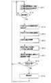
図2のフロ−チャートを用いて図1に示した可変色照明装置10の動作について説明する。
図2のフローチャートにおいて、ステップST11で出力値送信及び制御部54に現在出力値記憶部53から現在出力値が供給される。つぎに、ステップST12で現在出力値が測定周期かどうか判別される。
判別結果が測定周期でない場合即ち通常の点灯時である場合、ステップST11に戻り次の(現在出力値)データに基いて通常点灯用のパルスを出力するためのデータがRGB調光パルス発生装置30に供給され、RGB調光パルス発生装置30から出力された通常点灯パルスがRドライバー21、Gドライバー22、Bドライバー23に供給され、所望の光色、光量を発光する光源が駆動される。光源15のたとえばRLED16、GLED17,BLED18が駆動されて設定値に従って発光する。この状態が次の現在出力値記憶部53から現在値が入力されるまで継続される。
ステップST12で測定周期の場合ステップST13へ移行し、出力値送信及び制御部54から出力された光量制御データとタイミング制御信号などがRGB調光パルス発生装置30に出力され、そしてRLED16,GLED17,BLED18に時間的に互いに重複しないパルスを発生し、Rドライバー21、Gドライバー22、Bドライバー23に駆動パルスとして供給する。
たとえばRドライバー16で駆動された光源(R(赤)LED16)15から発光された光は光検出部80の受光素子(ホトディテクタ)83で光を電流に変換し、この光電流を増幅器81,82でアナログ電圧に変換して信号電圧を出力する。検出されたアナログ電圧はA/D変換部57でディジタル値に変換される。またGドライバー22で駆動された光源、G(緑)LED17から発光された光も同様に光検出部80で光−電流変換された後アナログ電圧として出力され、A/D変換57でディジタル値に変換される。さらに、Bドライバー23で駆動された光源、B(青)LED18で発光された光も同様に変換されて、A/D変換57でディジタル値に変換される。これらの、測定は時系列にお互いに重複しないように行われる(ステップST14)。The operation of the variable
In the flowchart of FIG. 2, the current output value is supplied from the current output
When the determination result is not the measurement cycle, that is, when the lighting is normal, the process returns to step ST11 and the data for outputting the pulse for normal lighting based on the next (current output value) data is the RGB dimming
In the case of the measurement cycle in step ST12, the process proceeds to step ST13, the light amount control data and timing control signal output from the output value transmission and
For example, light emitted from a light source (R (red) LED 16) 15 driven by an R driver 16 is converted into current by a light receiving element (photodetector) 83 of a
ステップST15において、A/D変換部57から出力されたRLED16、GLED17,BLED18の測定結果のディジタル化された光量データを用いてたとえばCPUで演算処理し、RGBの光量比率を求める。
つぎに、ステップST16において、製造時RGB比率記憶部71に記憶されていた値またはその後設定された基準値とステップST15で得られたデータをもとに、比較演算され、経時変化によるずれ幅などを求め、RGB出力値を得る。
ステップST17において、ステップST16で得られたRGB出力値を現在出力記憶部53と最終出力値記憶部72に出力し、それぞれの記憶部に記憶する。
現在出力値記憶部53に記憶されたRGB出力値は比較部52に供給される。また限界出力値記憶部51から光源15(RLED16、GLED17,BLED18)の限界寿命値が同時に供給され、比較される。RGB出力値が限界値より大きいとステップST11に移行し、ステップST11からステップST17を繰り返す。
一方、RGB出力値が限界値より小さいと、ステップST19に移行し、比較部52から出力された制御信号により寿命表示装置60に、光源15の特定の素子が寿命であることを表示する。そしてステップST11に戻り、同様な動作を繰り返す。In step ST15, for example, the CPU performs arithmetic processing using the digitized light amount data of the measurement results of the RLED 16, GLED 17, and
Next, in step ST16, a comparison operation is performed based on the value stored in the RGB
In step ST17, the RGB output values obtained in step ST16 are output to the current
The RGB output values stored in the current output
On the other hand, when the RGB output value is smaller than the limit value, the process proceeds to step ST19, and the
図2に示した光量検出方法は、RLED16、GLED17、BLED18の光量検出に時間差を設けて一つのフローで測定する方法であるが、それぞれ単独の流れでしかも時間間隔を設けて測定、演算処理する他の実施形態例があり、それを次に示す。図3に、LEDのR光量測定(RLED16の光量測定)、G光量測定(GLED17の光量測定)、B光量測定(BLED18の光量測定)を3つのグループとしてそれぞれ独立して測定している例のフローチャートを示す。また、各光源の光量測定方法は図2に示した方法と同じである。各光源の測定方法は図2と同じであるので、その個別光源に関する測定についての詳細な説明は省略する。
図3において、ステップST41とステップST42は図2のステップST11とステップST12と同じであり、ここで通常点灯時かまたは光量検出時かを判別している。
またステップST43からステップST45におけるR光源(赤LED)16の光量の検出動作はステップST13からステップST17に相当する。R光源(RLED16)を点灯させて、光量を測定し、その結果を記憶する。
その後、ステップST46において、R(赤)LED16、G(緑)LED17、B(青)LED18を駆動させて、混色発光(通常発光状態)を一定期間継続する。The light quantity detection method shown in FIG. 2 is a method in which a time difference is provided in the light quantity detection of the RLED 16, GLED 17, and
In FIG. 3, step ST41 and step ST42 are the same as step ST11 and step ST12 of FIG. 2, and it is discriminate | determined here at the time of normal lighting or the time of light quantity detection.
In addition, the light amount detection operation of the R light source (red LED) 16 from step ST43 to step ST45 corresponds to step ST13 to step ST17. The R light source (RLED 16) is turned on, the amount of light is measured, and the result is stored.
Thereafter, in step ST46, the R (red) LED 16, the G (green) LED 17, and the B (blue)
つぎに、G光源(G(緑)LED17)についても同様に、ステップST47からステップST49でG光源の光量の検出、データの保存を行う。ステップST50で、混色発光(通常発光状態)を一定期間継続する。
さらに、B光源(B(青)LED18)についても同様に、ステップST51からステップST53で光量の検出とそのデータを保存する。そして、ステップST54で混色発光(通常発光状態)を一定期間継続する。Next, similarly for the G light source (G (green) LED 17), the light amount of the G light source is detected and the data is stored in steps ST47 to ST49. In step ST50, the mixed color light emission (normal light emission state) is continued for a certain period.
Further, similarly for the B light source (B (blue) LED 18), the light amount detection and the data are stored in steps ST51 to ST53. In step ST54, the mixed color light emission (normal light emission state) is continued for a certain period.
各RLED16,GLED17,BLED18の光量のデータを用いて光量補正値と寿命表示について、ステップST55からステップST59で処理する。この処理方法は図2に示したステップST15からステップST19ものと同じである。
上述したように、RLED16,GLED17,BLED18の測定を単独で行ってもよい。Using the light quantity data of each RLED 16, GLED 17, and
As described above, the measurement of the RLED 16, the GLED 17, and the
また、図2と図3に示した光量補正のフローを、各光源の劣化による光量低下が色の変化として許容できない値になる前に行うと良い。上述した光源16の例として、今までLEDを用いてきた。このLEDは前述したように、通常劣化による光量低下には時間がかかるので、本補正のための周期は月単位の周期で十分性能を維持できる。
また、図1に示したように、光量検出部80に使用するセンサ(受光素子)はシリコンで形成された素子を使用することができる。このシリコンで形成されたセンサは、広い波長感度域を持ち、十分速い応答速度を持っている。応答速度が速いため、測定フローのための検出時間は1/100秒程度で十分可能であり、測定時の単独光源点灯によっても、人間の目には違和感をほとんど与えずに行うことが可能である。Also, the flow of light amount correction shown in FIGS. 2 and 3 may be performed before the light amount decrease due to deterioration of each light source becomes an unacceptable value as a color change. An LED has been used as an example of the light source 16 described above. As described above, since it takes time to reduce the amount of light due to normal deterioration, this LED can sufficiently maintain its performance with a period for this correction in a monthly unit.
Moreover, as shown in FIG. 1, the sensor (light receiving element) used for the light
図4に可変色照明装置90の概略構成図を示す。光量検出器は、RLED86,GLED87、BLED88で構成された光源部と、これらのLEDから発光された光を検出する受光素子89とで構成される。本実施形態例においては図1に図示した実施形態例と同様に、3個のLED光源と1個の受光素子で構成されている。
一方光源ドライブ回路、演算処理装置は、Rドライバー91、Gドライバー92、Bドライバー93、タイミング発生回路94、CPU96、A/D変換部95で構成されている。これらの動作は図1に示したものと同じである。FIG. 4 shows a schematic configuration diagram of the variable color illumination device 90. The light quantity detector includes a light source unit composed of RLEDs 86,
On the other hand, the light source drive circuit and the arithmetic processing unit include an
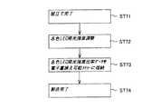
図5と図6に可変色照明装置90の製造方法の主要部を示す。図5において他の実施形態例である第1の製造方法についてのフローチャートを示す。製造工程の組み立て方法については、本発明においては主たる目的でないので省略する。組み立てが完了すると(ステップST71)、ステップST72において、各LED発光強度の調整を行う。この調整は、可変すべき各色温度、または必要光色の数に応じて繰り返し行う。
ステップST73において、各色LED発光強度比率データを電気的に書き換え可能なメモリー(フラッシュメモリーなど)に格納し、製造が完了する(ステップST74)。この格納するメモリーは図1に図示した製造時RGB比率記憶部71に相当する。5 and 6 show the main part of the method for manufacturing the variable color illumination device 90. FIG. In FIG. 5, the flowchart about the 1st manufacturing method which is another example of embodiment is shown. The assembly method of the manufacturing process is omitted because it is not the main purpose in the present invention. When the assembly is completed (step ST71), each LED light emission intensity is adjusted in step ST72. This adjustment is repeated according to each color temperature to be varied or the number of required light colors.
In step ST73, each color LED emission intensity ratio data is stored in an electrically rewritable memory (flash memory or the like), and the manufacturing is completed (step ST74). This stored memory corresponds to the RGB
図6に他の実施形態例の第2の製造方法に関するフローチャートを示す。
ステップST81において、組み立て完了後、黒体放射に関連するプランクの法則またはウイーンの法則の式をCPUのメモリーのプログラム内に格納する。
ステップST82において、各色光源(たとえばRLED86、GLED87,BLED88)の発光強度を調整する。調整は、光源の数に応じて繰り返し行う。
ステップST83において、各色光源の調整による補正値を書き換え可能メモリーに格納し、製造を完了する(ステップST84)。
本方法においては、黒体放射のどの色温度に対しても、全ての調整値をメモリーに記憶させる必要は無い。また、プランクの法則として知られる、黒体放射のスペクトル計算式をCPU(演算処理装置、コンピュータ)のメモリーに記憶させておき、各色温度による各光源の発光強度をそれぞれの補正値を与えて決定する。この場合、プランクの式と補正値を記憶するだけでよい。FIG. 6 shows a flowchart relating to the second manufacturing method of another embodiment.
In step ST81, after the assembly is completed, Planck's law or Wien's law expression related to black body radiation is stored in a program in the memory of the CPU.
In step ST82, the light emission intensity of each color light source (for example, RLED86, GLED87, BLED88) is adjusted. The adjustment is repeated according to the number of light sources.
In step ST83, the correction value obtained by adjusting each color light source is stored in a rewritable memory, and the manufacturing is completed (step ST84).
In this method, it is not necessary to store all adjustment values in memory for any color temperature of blackbody radiation. Also, a black body radiation spectrum calculation formula, known as Planck's law, is stored in the memory of a CPU (arithmetic processing unit, computer), and the emission intensity of each light source at each color temperature is determined by giving each correction value. To do. In this case, it is only necessary to store the Planck's formula and the correction value.
光色設定の原理に基いて製造時RGB比率記憶部71にデータがプリセットされ、また最終出力値記憶部72に記憶された補正値もこの原理に基いて最終的にはRGB比率が決定される。
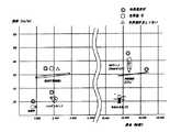
以下具体的に光色設定の原理について示す。図7は色度図を示したものである。この座標中に示される、B点で示され480nmの波長を発光するLEDと、Y点で示される580nmの波長を発光するLEDの2個発光させ混色させた場合、B及びYのLEDの発光強度の比によって、B及びYの二点を結ぶ線上の光色を混色によって得ることができる。
また図7には、自然界の存在する自然光(黒体放射)の温度によって変化を示す曲線が示されている。前述のY及びBを結ぶ線と、この黒体放射曲線は近似しており、Y及びBの発光強度比によって、座標上に示すように、3000Kから7500K(ケルビン)までの発光色が得られることが示されている。
つぎに、2点光源を3点光源に展開した場合について述べる。図7の色度座標中において、点Bで示される480nmの波長を発光するLEDと、点Gで示される520nmの波長を発光するLEDと点Rで示される620nmの波長を発光するLEDの3個を発光し混色させた場合、B,G及びRのLEDの発光強度の比によって、座標B,G及びRの三点を結ぶ領域内の光色を混色によって得ることができる。色度図から明らかなように、上述の3点を結ぶ領域内の色は、色度図全域の過半数の色を創出できることを示している。Based on the principle of light color setting, data is preset in the manufacturing RGB
The principle of light color setting will be specifically described below. FIG. 7 shows a chromaticity diagram. When two LEDs, a LED emitting light having a wavelength of 480 nm indicated by a point B and a LED emitting light having a wavelength of 580 nm indicated by a Y point, are emitted and mixed, the B and Y LEDs emit light. Depending on the intensity ratio, the light color on the line connecting the two points B and Y can be obtained by color mixing.
Further, FIG. 7 shows a curve showing a change depending on the temperature of natural light (black body radiation) in the natural world. The black body radiation curve approximates the line connecting Y and B described above, and emission colors from 3000K to 7500K (Kelvin) can be obtained by the emission intensity ratio of Y and B as shown on the coordinates. It has been shown.
Next, a case where a two-point light source is developed into a three-point light source will be described. In the chromaticity coordinates of FIG. 7, three of an LED emitting a wavelength of 480 nm indicated by a point B, an LED emitting a wavelength of 520 nm indicated by a point G, and an LED emitting a wavelength of 620 nm indicated by a point R. When light is emitted and mixed, the light color in the region connecting the three points of coordinates B, G, and R can be obtained by mixing the colors according to the ratio of the emission intensity of the B, G, and R LEDs. As is apparent from the chromaticity diagram, the colors in the region connecting the three points described above can create a majority of the colors in the entire chromaticity diagram.
図8に代表的な光源の分光分布図を示す。
図8(A)において、たとえば曲線aは標準の光D65で、紫外線を含む太陽の光を元にした、CIE,ISOの基準光(6504K)を示す。曲線cは白熱電球の標準光源(2856K)、図8(B)の曲線dは白色蛍光灯、曲線eは昼光色蛍光灯、曲線fは3波長形昼白色蛍光灯のそれぞれの波長に対する光強度を示す。
曲線aの標準光は400nmから700nmの範囲において発光強度が約75以上でほぼ均一な発光強度を持つことを示している。曲線cの白熱電球は短波長側の発光強度は小さいが、長波長側の発光強度は大きいことを示している。曲線fの3波長形昼白色蛍光灯は約430nm、540nmと620nmの3箇所にピークを有し、白色を発光していることを示している。FIG. 8 shows a spectral distribution diagram of a typical light source.
In FIG. 8A, for example, a curve a is standard light D65, and shows CIE and ISO reference light (6504K) based on solar light including ultraviolet rays. Curve c is the standard light source (2856K) of the incandescent bulb, curve d in FIG. 8B is the white fluorescent lamp, curve e is the daylight fluorescent lamp, and curve f is the light intensity for each wavelength of the three-wavelength day white fluorescent lamp. Show.
The standard light of the curve a indicates that the emission intensity is about 75 or more in the range of 400 nm to 700 nm and has a substantially uniform emission intensity. The incandescent lamp of the curve c shows that the emission intensity on the short wavelength side is small, but the emission intensity on the long wavelength side is high. The three-wavelength daylight white fluorescent lamp of curve f has peaks at three locations of about 430 nm, 540 nm, and 620 nm, indicating that white light is emitted.
図9に各光源に対する効率(lm/W;ルーメン/ワット)と寿命(時間)を示したグラフを示す。白熱球の効率は20[lm/W]で寿命は1000時間以下である。ハロゲンランプは約35[lm/W]、寿命は2000時間弱である、蛍光灯(熱陰極)は70[lm/W]、寿命は1500〜2200時間で、効率は前者より良い。
HIDランプ(メタルハライドランプ)は効率が良く約90[lm/W]で、かつ寿命も20000時間以上である。冷陰極管の発光効率は約65[lm/W]、寿命は30000時間以上である。また青色&白色LEDの効率は約25[lm/W]であるが、寿命は20000時間弱と長いのが特徴である。また、これらの光源の内、青色&白色LEDを除いた光源は一般に色再現が良好である。FIG. 9 is a graph showing the efficiency (lm / W; lumen / watt) and life (time) for each light source. The efficiency of the incandescent bulb is 20 [lm / W] and the lifetime is 1000 hours or less. The halogen lamp has a life of about 35 [lm / W] and a life of less than 2000 hours, the fluorescent lamp (hot cathode) has a life of 70 [lm / W], a life of 1500 to 2200 hours, and the efficiency is better than the former.
The HID lamp (metal halide lamp) has high efficiency and is about 90 [lm / W] and has a lifetime of 20000 hours or more. The cold cathode tube has a luminous efficiency of about 65 [lm / W] and a lifetime of 30,000 hours or more. The efficiency of the blue & white LED is about 25 [lm / W], but the lifetime is as long as a little less than 20000 hours. Of these light sources, light sources other than blue and white LEDs generally have good color reproduction.
図10に白色LEDのスペクトルに対する相対的発光強度のグラフを示す。横軸に波長λ[nm]、400nmから700nmの範囲を示し、縦軸には相対的な発光強度を任意目盛[a.u.]、0〜100を示している。白色LEDの発光強度は420nmから急激に立ち上がり約470nmで最大の第1のピーク(100[a.u.])を示し、その後500nmまで減少し、また増加して約560nmで第2のピーク(40[a.u.])を示す。そして、波長が増加するに伴い単調減少し、700nmで10[a.u.]以下となる。
したがって、この白色LEDは700nm近傍の発光強度が10[a.u.]以下で、相対的に赤の色が非常に少ないことが分かる。この光で対象物を照明した場合、赤い色がくすんでしまう。FIG. 10 shows a graph of relative light emission intensity with respect to the spectrum of the white LED. The horizontal axis indicates the wavelength λ [nm] and the range from 400 nm to 700 nm, and the vertical axis indicates the relative light emission intensity on an arbitrary scale [a. u. ], 0 to 100. The emission intensity of the white LED rises rapidly from 420 nm, shows the maximum first peak (100 [au]] at about 470 nm, then decreases to 500 nm, and increases to the second peak at about 560 nm ( 40 [au]]). As the wavelength increases, it decreases monotonously at 10 nm at 700 nm. u. It becomes the following.
Therefore, the white LED has a light emission intensity in the vicinity of 700 nm of 10 [a. u. In the following, it can be seen that there is relatively little red color. If the object is illuminated with this light, the red color will be dull.
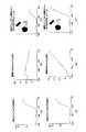
図11にたとえば試料(りんご)に標準の光D56(太陽光)と標準光の白熱球を光源として照射した場合の分光反射率を示す。
図11(A)に試料(りんご)の分光反射率を示す。横軸に波長を示し、400nm〜700nmを示し、縦軸に分光反射率の相対値0〜100%を示す。分光反射率は400nm〜580nmまで10%以下で、600nm以上になると急激に増加し、650nmで約70%となり、その後飽和特性を示し、700nmで約70%となる。
一方、図11(B)に標準の光D65の分光分布を示す。400nmで約80[lm/W]、480nmで約120[lm/W]のピークを示し、その後波長の増加とともに単調減少し700nmで約70[lm/W]である。
図11(C)に、試料(りんご)に標準の光を照射した時の反射される光の分光分布を示す。これは、図11(A)の試料(りんご)の分光反射率と図11(B)の標準の光の分光分布を乗算したものであるから、図から、約600nm〜700nmの範囲の反射される光の分光分布が減少していることが分かる。これは試料(りんご)の赤色がややくすんだことを示している。FIG. 11 shows the spectral reflectance when, for example, a sample (apple) is irradiated with standard light D56 (sunlight) and an incandescent bulb of standard light as a light source.
FIG. 11A shows the spectral reflectance of the sample (apple). The abscissa indicates the wavelength, 400 nm to 700 nm, and the ordinate indicates the relative spectral reflectance of 0 to 100%. Spectral reflectance is 10% or less from 400 nm to 580 nm, and increases rapidly when it is 600 nm or more, and is about 70% at 650 nm, and then exhibits saturation characteristics, and is about 70% at 700 nm.
On the other hand, FIG. 11B shows the spectral distribution of the standard light D65. It shows a peak of about 80 [lm / W] at 400 nm and about 120 [lm / W] at 480 nm, and then monotonically decreases with an increase in wavelength, and is about 70 [lm / W] at 700 nm.
FIG. 11C shows a spectral distribution of reflected light when the sample (apple) is irradiated with standard light. This is obtained by multiplying the spectral reflectance of the sample (apple) in FIG. 11 (A) by the spectral distribution of the standard light in FIG. 11 (B). It can be seen that the spectral distribution of light decreases. This indicates that the red color of the sample (apple) is slightly dull.
つぎに、同じ試料(りんご)(図11(D))に標準の光の白熱球で照射した場合について述べる。白熱球の光の分光分布を図11(E)に示す。400nmで約20[lm/W]で、450nmまで下に凸の曲線を示し単調増加し、450nmで約25[lm/W]で、それから直線的に増加し、700nmで約200[lm/W]である。
そして、図11(F)に示すように、試料(りんご)から反射される光の分光分布は、前述と同様に、図11(D)の試料(りんご)の分光反射率と図11(E)の標準の光の分光分布を乗算したものであるから、波長600nm以下では分光分布の値は小さく、600nm以上で急激に増加していることを示している。これは、長波長側の光を強調していることを示し、試料(りんご)がより赤色を帯びていることを示している。Next, the case where the same sample (apple) (FIG. 11D) is irradiated with a standard incandescent bulb will be described. The spectral distribution of incandescent light is shown in FIG. It is about 20 [lm / W] at 400 nm, shows a convex curve down to 450 nm, increases monotonically, increases at about 25 [lm / W] at 450 nm, and then increases linearly, and increases at about 200 [lm / W at 700 nm. ].
As shown in FIG. 11F, the spectral distribution of the light reflected from the sample (apple) is similar to the spectral reflectance of the sample (apple) in FIG. ) Is multiplied by the spectral distribution of the standard light, indicating that the value of the spectral distribution is small at wavelengths of 600 nm or less and increases rapidly at 600 nm or more. This indicates that the light on the long wavelength side is emphasized, and the sample (apple) is more reddish.
このように、光源の分光分布特性により、試料から反射される分光分布が異なるため、実際とは異なる色に見えることがある。これを改善するには光源の分光特性を変えるとよい。また一度光源の光色(と光量)を設定しても、光源にLEDを使用した場合経時変化により光色が変化することもある。このような場合、前述した色可変照明装置またはその補正方法を用いて、実際の色に近づけることもできる。 In this way, the spectral distribution reflected from the sample differs depending on the spectral distribution characteristics of the light source, so that it may look different from the actual color. To improve this, the spectral characteristics of the light source should be changed. Even if the light color (and the amount of light) of the light source is set once, the light color may change due to changes over time when an LED is used as the light source. In such a case, the color can be brought close to an actual color by using the color variable illumination device or the correction method described above.
つぎに、本可変色照明装置を用いた応用例である他の実施形態例を示す。
たとえば3個のRLED,GLED,BLEDを用いて可変色のスポット照明装置を設け、広角度に照明を照らし、たとえば筆記用具などの文具に任意の光色をあてて展示することができる。とくに可変色スポット照明装置の場合、3個のLEDの発光比率を可変できるので、光色、光量を変化させて雰囲気を変えて展示することができる。またLEDの発光比率を可変して、製品の色を可変して、対象製品に照射することにより特定の光を強調して展示することもできる。
さらに上述した3個のLEDを用いたフルカラー照明は、たとえばカラフルな店舗の照明や、食品・服飾・化粧など色が重要な分野に用途があり、その目的に応じて、自然光(太陽光〜白熱球)に至るまで、どんな光でも再現できる。
スポット照明の実施形態例として、スポットライトの投光角度を可変にして、読書灯として用いることができる。光源に、複数個たとえば3個のLEDを用いて3波長形昼白色蛍光灯とすることもできるし、さらに、読書環境(部屋)などに合わせて光色を可変することもできる。
またスポット照明では広角度照明とは逆に、狭角度照明も行うこともできる。Next, another embodiment which is an application example using the variable color illumination device will be described.
For example, a variable color spot illumination device can be provided using three RLEDs, GLEDs, and BLEDs, and illumination can be performed at a wide angle, and an arbitrary light color can be applied to a stationery such as a writing instrument. Particularly in the case of a variable color spot illumination device, the light emission ratio of the three LEDs can be varied, so that the atmosphere can be changed by changing the light color and the amount of light. It is also possible to display a product with a specific light emphasized by changing the light emission ratio of the LED, changing the color of the product, and irradiating the target product.
Furthermore, full-color lighting using the three LEDs described above has applications in fields where color is important, such as colorful store lighting and food, clothing, and makeup. Depending on the purpose, natural light (sunlight to incandescent) Any light can be reproduced.
As an example of spot illumination, the light projection angle of the spotlight can be made variable and used as a reading lamp. A plurality of, for example, three LEDs can be used as the light source to form a three-wavelength daylight white fluorescent lamp, and the light color can be changed according to the reading environment (room).
In contrast to spot illumination, spot illumination can also perform narrow angle illumination.
LEDなどを用いたスポット照明の場合、低消費電力でかつ50000時間以上の長寿命で、小型化できる特徴がある。
またこれ以外に、LED光源を直線状に配列したリニアライトユニットもある。これは、リニアライトをガラスやアクリルできた棚板の上下に備え付け、光源からの光をこの棚板で反射させて、棚板を明るくすることも、棚板下を明るくすることも可能である。
リニアライトの他の実施形態例として、フィルムポスターの端部にリニアライトを設けその光源とすることができる。これ以外にも、病院でX線フィルム観察用のパネルライトとして使用することができる。
また、光色、光量を可変することができるから、美容院や歯科医での光源として用いることができる。In the case of spot lighting using an LED or the like, there is a feature that it can be miniaturized with low power consumption and a long life of 50000 hours or more.
In addition, there is a linear light unit in which LED light sources are arranged in a straight line. It is possible to make linear shelves brighter under the shelves by attaching linear lights to the top and bottom of shelves made of glass or acrylic and reflecting light from the light source on these shelves. .
As another embodiment of the linear light, a linear light can be provided at the end of the film poster as the light source. In addition, it can be used as a panel light for X-ray film observation in a hospital.
Further, since the light color and the amount of light can be varied, it can be used as a light source in a beauty salon or a dentist.
このように、可変色照明装置は、環境に応じてより適切な色での照明を可能とすると共に、長時間安定した色を再現することができる。
上述したように、光源にたとえばLED(Light Emitting Diode;発光ダイオード)に同じ電流を流していても、経時変化によりLEDの特性は変化することが知られている。この変化は、それぞれのLED特有のもので、使用時間経過による特性の変化で、初期に合成された光は、同じ色を保つことができなかった。しかし、LEDなどの光源から発生した光を受光素子によって測定し、初期の設定から変化した値を、1個の受光素子で時系列的に重複しないように測定し、その測定結果から補正値を演算し、それぞれのLEDに流す電流を補正することで、一定の色を保つことが可能となる。
また、複数の光源から1個の受光素子で光量を検出して、光色、光量を求め、任意の混色光を発生することができるので、種々の光源に用いることができるとともに光検出器を小形にすることができる。また回路を小形したことにより消費電流を削減できる。さらに光源にLEDを用いた場合、寿命が従来の光源と比較して長いので上述したように種々の分野に適用できる。In this way, the variable color illumination device can illuminate with a more appropriate color according to the environment and can reproduce a stable color for a long time.
As described above, it is known that even if the same current is supplied to a light source, for example, an LED (Light Emitting Diode), the characteristics of the LED change with time. This change is peculiar to each LED, and the light synthesized in the initial stage cannot keep the same color due to a change in characteristics over time. However, light generated from a light source such as an LED is measured by a light receiving element, a value changed from the initial setting is measured so as not to overlap in time series with one light receiving element, and a correction value is calculated from the measurement result. It is possible to maintain a certain color by calculating and correcting the current flowing through each LED.
In addition, it is possible to detect the light amount from a plurality of light sources with one light receiving element to obtain the light color and the light amount, and to generate arbitrary color mixture light, so that it can be used for various light sources and the photodetector. Can be small. Further, the current consumption can be reduced by downsizing the circuit. Further, when an LED is used as the light source, the lifetime is longer than that of a conventional light source, and thus it can be applied to various fields as described above.
10,100…可変色照明装置、15,104…光源部、21,91…Rドライバー、22,92…Gドライバー、23,93…Bドライバー、30…RGB調光パルス発生装置、50…CPU(演算処理装置)、51…限界出力値記憶部、52…比較部、53…現在出力値記憶部、54…出力値送信及び制御部、55…基準RGB比率との比較による出力値演算部、56…測定結果RGB比率演算部、57,95…A/D変換部(アナログ−ディジタル変換器;A/D−C)、58,94…タイミング発生部(回路)、60…寿命表示装置、70…CPU外不揮発性メモリー、71…製造時RGB比率記憶部、72…最終出力値記憶部、80…光検出部、82…増幅記、83,89…受光素子、86…R(赤)LED,87…G(緑)LED、88…B(青)LED、101…照明器具部、102…調光制御部、103…リモコン送信部、115…光色・光量検出部、116…受信側CPU。DESCRIPTION OF SYMBOLS 10,100 ... Variable color illuminating device, 15, 104 ... Light source part, 21, 91 ... R driver, 22, 92 ... G driver, 23, 93 ... B driver, 30 ... RGB dimming pulse generator, 50 ... CPU ( (Arithmetic processing device), 51 ... limit output value storage unit, 52 ... comparison unit, 53 ... current output value storage unit, 54 ... output value transmission and control unit, 55 ... output value calculation unit by comparison with reference RGB ratio, 56 ... Measurement result RGB ratio calculation unit, 57,95 ... A / D conversion unit (analog-digital converter; A / D-C), 58,94 ... timing generation unit (circuit), 60 ... life display device, 70 ... Non-CPU non-volatile memory, 71... RGB ratio storage unit during manufacture, 72... Final output value storage unit, 80... Photodetection unit, 82 ... Amplification, 83, 89. ... G (green) LE , 88 ... B (blue) LED, 101 ... lighting fixture unit, 102 ... light control unit, 103 ... remote control transmitting section, 115 ... light color, light quantity detecting unit, 116 ... reception side CPU.
Claims (5)
Translated fromJapanese前記各光源の調光を独立して行う制御装置と、
前記光源の発光量を検出する1個の受光装置と、
所望の光色を得るためプリセットされる前記各光源の光量比率を記憶する記憶装置と、
前記受光装置で検出された前記各光源の光量比率と前記プリセットされた光量比率から変動値を求め、該変動値を補正出力とし前記制御装置にフィードバックする演算装置と
を有する可変色照明装置。At least two color light sources;
A control device for independently performing dimming of each light source;
One light receiving device for detecting the light emission amount of the light source;
A storage device for storing a light quantity ratio of each of the light sources preset to obtain a desired light color;
A variable color illumination device, comprising: an arithmetic unit that obtains a variation value from the light amount ratio of each light source detected by the light receiving device and the preset light amount ratio and feeds the variation value as a correction output to the control device.
請求項1記載の可変色照明装置。The variable color illumination device according to claim 1, wherein the arithmetic device includes a time adjusting unit that generates a time interval of the feedback and a time required for light amount detection.
請求項1または2記載の可変色照明装置。The variable color illumination device according to claim 1 or 2, wherein the light amount detection of each of the light sources is detected in time series and then corrected.
請求項1から3のいずれかに記載の可変色照明装置。The variable color illumination device according to any one of claims 1 to 3, wherein the calculation of light detection and correction output of each light source is processed independently, and the light source is turned on during the processing.
請求項1から4のいずれかに記載の可変色照明装置。A storage device that stores the limit value of the light source dimming control value, and that the output value calculated from the light amount of each light source obtained by feedback exceeds the limit value, informs that the light source is at the end of its life. The variable color illumination device according to claim 1, further comprising a notification unit.
Priority Applications (3)
| Application Number | Priority Date | Filing Date | Title |
|---|---|---|---|
| JP2005012753AJP2006202602A (en) | 2005-01-20 | 2005-01-20 | Variable color lighting device |
| US11/795,579US20080088244A1 (en) | 2005-01-20 | 2006-01-20 | Variable Color Illumination Apparatus |
| PCT/JP2006/300823WO2006077955A1 (en) | 2005-01-20 | 2006-01-20 | Variable color lighting device |
Applications Claiming Priority (1)
| Application Number | Priority Date | Filing Date | Title |
|---|---|---|---|
| JP2005012753AJP2006202602A (en) | 2005-01-20 | 2005-01-20 | Variable color lighting device |
Publications (1)
| Publication Number | Publication Date |
|---|---|
| JP2006202602Atrue JP2006202602A (en) | 2006-08-03 |
Family
ID=36692336
Family Applications (1)
| Application Number | Title | Priority Date | Filing Date |
|---|---|---|---|
| JP2005012753AAbandonedJP2006202602A (en) | 2005-01-20 | 2005-01-20 | Variable color lighting device |
Country Status (3)
| Country | Link |
|---|---|
| US (1) | US20080088244A1 (en) |
| JP (1) | JP2006202602A (en) |
| WO (1) | WO2006077955A1 (en) |
Cited By (13)
| Publication number | Priority date | Publication date | Assignee | Title |
|---|---|---|---|---|
| JP2008210535A (en)* | 2007-02-23 | 2008-09-11 | Sharp Corp | LED lighting equipment |
| JP2010518592A (en)* | 2007-02-14 | 2010-05-27 | クリー インコーポレイテッド | System and method for split processor control in a solid state lighting panel |
| JP2012119089A (en)* | 2010-11-29 | 2012-06-21 | Panasonic Corp | Lighting device |
| JP2013514629A (en)* | 2009-12-17 | 2013-04-25 | アルコン リサーチ, リミテッド | Dichroic white light illuminator for eyeball |
| JP2016179173A (en)* | 2015-03-06 | 2016-10-13 | シンプルヒューマン・エルエルシー | Vanity mirror |
| US9635729B2 (en) | 2015-09-10 | 2017-04-25 | Panasonic Intellectual Property Management Co., Ltd. | Illumination device and illumination system and mobile body including the same |
| US11371692B2 (en) | 2012-03-08 | 2022-06-28 | Simplehuman, Llc | Vanity mirror |
| US11640042B2 (en) | 2019-03-01 | 2023-05-02 | Simplehuman, Llc | Vanity mirror |
| USD990174S1 (en) | 2019-03-01 | 2023-06-27 | Simplehuman, Llc | Vanity mirror |
| US11708031B2 (en) | 2018-03-22 | 2023-07-25 | Simplehuman, Llc | Voice-activated vanity mirror |
| US11819107B2 (en) | 2017-03-17 | 2023-11-21 | Simplehuman, Llc | Vanity mirror |
| US12225999B2 (en) | 2018-09-19 | 2025-02-18 | Simplehuman, Llc | Vanity mirror |
| US12396577B2 (en) | 2023-03-03 | 2025-08-26 | Simplehuman, Llc | Vanity mirror with hidden sensor |
Families Citing this family (21)
| Publication number | Priority date | Publication date | Assignee | Title |
|---|---|---|---|---|
| US8669716B2 (en) | 2007-08-30 | 2014-03-11 | Wireless Environment, Llc | Wireless light bulb |
| US8203445B2 (en)* | 2006-03-28 | 2012-06-19 | Wireless Environment, Llc | Wireless lighting |
| US8519566B2 (en) | 2006-03-28 | 2013-08-27 | Wireless Environment, Llc | Remote switch sensing in lighting devices |
| EP2039226B1 (en)* | 2006-06-28 | 2012-08-15 | Philips Intellectual Property & Standards GmbH | Method of controlling a lighting system based on a target light distribution |
| JP2008042329A (en)* | 2006-08-02 | 2008-02-21 | Canon Inc | Image reading apparatus and control method thereof |
| JP2008117713A (en)* | 2006-11-07 | 2008-05-22 | Sharp Corp | Backlight device and video display device |
| JP5400053B2 (en)* | 2007-11-06 | 2014-01-29 | コーニンクレッカ フィリップス エヌ ヴェ | Light control system and method for automatically rendering a lighting scene |
| EP2289179B1 (en)* | 2008-05-06 | 2017-01-04 | Philips Lighting Holding B.V. | Light module, illumination system and method incorporating data in light emitted |
| CA2957199C (en) | 2008-11-26 | 2019-01-08 | Wireless Environment, Llc | Wireless lighting devices and applications |
| US8598793B2 (en) | 2011-05-12 | 2013-12-03 | Ledengin, Inc. | Tuning of emitter with multiple LEDs to a single color bin |
| CN102577604A (en)* | 2009-09-23 | 2012-07-11 | 皇家飞利浦电子股份有限公司 | Color control of lighting system |
| US8779685B2 (en) | 2009-11-19 | 2014-07-15 | Intematix Corporation | High CRI white light emitting devices and drive circuitry |
| US9345095B2 (en) | 2010-04-08 | 2016-05-17 | Ledengin, Inc. | Tunable multi-LED emitter module |
| US8946998B2 (en)* | 2010-08-09 | 2015-02-03 | Intematix Corporation | LED-based light emitting systems and devices with color compensation |
| JP5605702B2 (en)* | 2010-12-21 | 2014-10-15 | 東芝ライテック株式会社 | Lighting device |
| EP2523534B1 (en)* | 2011-05-12 | 2019-08-07 | Ledengin, Inc. | Apparatus and methods for tuning of emitter with multiple LEDs to a single color bin |
| US10257988B2 (en)* | 2011-12-02 | 2019-04-16 | Biological Illumination, Llc | Illumination and grow light system and associated methods |
| US11032884B2 (en) | 2012-03-02 | 2021-06-08 | Ledengin, Inc. | Method for making tunable multi-led emitter module |
| US10721808B2 (en) | 2012-07-01 | 2020-07-21 | Ideal Industries Lighting Llc | Light fixture control |
| TWI436030B (en)* | 2012-07-04 | 2014-05-01 | Test Research Inc | Three-dimensional measuring system |
| US10575374B2 (en) | 2018-03-09 | 2020-02-25 | Ledengin, Inc. | Package for flip-chip LEDs with close spacing of LED chips |
Citations (4)
| Publication number | Priority date | Publication date | Assignee | Title |
|---|---|---|---|---|
| JPS60124398A (en)* | 1983-12-08 | 1985-07-03 | 三菱電機株式会社 | Color dimmer |
| JPH0513178A (en)* | 1991-07-02 | 1993-01-22 | Mitsubishi Electric Corp | Backlight for liquid crystal display device and liquid crystal display device |
| JPH0521168A (en)* | 1991-07-15 | 1993-01-29 | Matsushita Electric Works Ltd | Variable color lighting system |
| WO2003075617A1 (en)* | 2002-03-01 | 2003-09-12 | Sharp Kabushiki Kaisha | Light emitting device and display unit using the light emitting device and reading device |
Family Cites Families (6)
| Publication number | Priority date | Publication date | Assignee | Title |
|---|---|---|---|---|
| JP4201070B2 (en)* | 2000-06-28 | 2008-12-24 | エルジー ディスプレイ カンパニー リミテッド | Apparatus and method for correcting gamma voltage of liquid crystal display device |
| US6888529B2 (en)* | 2000-12-12 | 2005-05-03 | Koninklijke Philips Electronics N.V. | Control and drive circuit arrangement for illumination performance enhancement with LED light sources |
| US8100552B2 (en)* | 2002-07-12 | 2012-01-24 | Yechezkal Evan Spero | Multiple light-source illuminating system |
| JP4100299B2 (en)* | 2003-08-29 | 2008-06-11 | ソニー株式会社 | Driving device, driving method, and display panel driving system |
| US7026769B2 (en)* | 2003-12-18 | 2006-04-11 | Joon Chok Lee | Luminary control system adapted for reproducing the color of a known light source |
| EP3589081B1 (en)* | 2004-03-15 | 2024-02-21 | Signify North America Corporation | Power control methods and apparatus |
- 2005
- 2005-01-20JPJP2005012753Apatent/JP2006202602A/ennot_activeAbandoned
- 2006
- 2006-01-20WOPCT/JP2006/300823patent/WO2006077955A1/ennot_activeApplication Discontinuation
- 2006-01-20USUS11/795,579patent/US20080088244A1/ennot_activeAbandoned
Patent Citations (4)
| Publication number | Priority date | Publication date | Assignee | Title |
|---|---|---|---|---|
| JPS60124398A (en)* | 1983-12-08 | 1985-07-03 | 三菱電機株式会社 | Color dimmer |
| JPH0513178A (en)* | 1991-07-02 | 1993-01-22 | Mitsubishi Electric Corp | Backlight for liquid crystal display device and liquid crystal display device |
| JPH0521168A (en)* | 1991-07-15 | 1993-01-29 | Matsushita Electric Works Ltd | Variable color lighting system |
| WO2003075617A1 (en)* | 2002-03-01 | 2003-09-12 | Sharp Kabushiki Kaisha | Light emitting device and display unit using the light emitting device and reading device |
Cited By (25)
| Publication number | Priority date | Publication date | Assignee | Title |
|---|---|---|---|---|
| US8456388B2 (en) | 2007-02-14 | 2013-06-04 | Cree, Inc. | Systems and methods for split processor control in a solid state lighting panel |
| JP2010518592A (en)* | 2007-02-14 | 2010-05-27 | クリー インコーポレイテッド | System and method for split processor control in a solid state lighting panel |
| JP2008210535A (en)* | 2007-02-23 | 2008-09-11 | Sharp Corp | LED lighting equipment |
| JP2013514629A (en)* | 2009-12-17 | 2013-04-25 | アルコン リサーチ, リミテッド | Dichroic white light illuminator for eyeball |
| JP2012119089A (en)* | 2010-11-29 | 2012-06-21 | Panasonic Corp | Lighting device |
| US11859807B2 (en) | 2012-03-08 | 2024-01-02 | Simplehuman, Llc | Vanity mirror |
| US11371692B2 (en) | 2012-03-08 | 2022-06-28 | Simplehuman, Llc | Vanity mirror |
| US12313253B2 (en) | 2012-03-08 | 2025-05-27 | Simplehuman, Llc | Vanity mirror |
| USD1059051S1 (en) | 2012-03-08 | 2025-01-28 | Simplehuman, Llc | Vanity mirror |
| USD1009485S1 (en) | 2012-03-08 | 2024-01-02 | Simplehuman, Llc | Vanity mirror |
| JP2016179173A (en)* | 2015-03-06 | 2016-10-13 | シンプルヒューマン・エルエルシー | Vanity mirror |
| JP7025111B2 (en) | 2015-03-06 | 2022-02-24 | シンプルヒューマン・エルエルシー | Vanity mirror |
| US11622614B2 (en) | 2015-03-06 | 2023-04-11 | Simplehuman, Llc | Vanity mirror |
| US12376668B2 (en) | 2015-03-06 | 2025-08-05 | Simplehuman, Llc | Vanity mirror with second mirror assembly magnetically attached thereto |
| US12102211B2 (en) | 2015-03-06 | 2024-10-01 | Simplehuman, Llc | Vanity mirror with second mirror assembly magnetically attached thereto |
| US9635729B2 (en) | 2015-09-10 | 2017-04-25 | Panasonic Intellectual Property Management Co., Ltd. | Illumination device and illumination system and mobile body including the same |
| US11819107B2 (en) | 2017-03-17 | 2023-11-21 | Simplehuman, Llc | Vanity mirror |
| US12329268B2 (en) | 2017-03-17 | 2025-06-17 | Simplehuman, Llc | Vanity mirror |
| US11708031B2 (en) | 2018-03-22 | 2023-07-25 | Simplehuman, Llc | Voice-activated vanity mirror |
| US12225999B2 (en) | 2018-09-19 | 2025-02-18 | Simplehuman, Llc | Vanity mirror |
| US12153284B2 (en) | 2019-03-01 | 2024-11-26 | Simplehuman, Llc | Vanity mirror |
| USD1063410S1 (en) | 2019-03-01 | 2025-02-25 | Simplehuman, Llc | Vanity mirror |
| USD990174S1 (en) | 2019-03-01 | 2023-06-27 | Simplehuman, Llc | Vanity mirror |
| US11640042B2 (en) | 2019-03-01 | 2023-05-02 | Simplehuman, Llc | Vanity mirror |
| US12396577B2 (en) | 2023-03-03 | 2025-08-26 | Simplehuman, Llc | Vanity mirror with hidden sensor |
Also Published As
| Publication number | Publication date |
|---|---|
| WO2006077955A1 (en) | 2006-07-27 |
| US20080088244A1 (en) | 2008-04-17 |
Similar Documents
| Publication | Publication Date | Title |
|---|---|---|
| JP2006202602A (en) | Variable color lighting device | |
| US10433392B2 (en) | Lighting having spectral content synchronized with video | |
| US8653758B2 (en) | Circuit for and a method of sensing a property of light | |
| US7572028B2 (en) | Methods and apparatus for generating and modulating white light illumination conditions | |
| US7520634B2 (en) | Methods and apparatus for controlling a color temperature of lighting conditions | |
| JP4684271B2 (en) | An efficient solid-state light source that emits light in a limited area of color space | |
| ES2547927T3 (en) | White light generation with light emitting diodes that have different spectrum | |
| JP5424888B2 (en) | Method and apparatus for determining a driving value for driving a light emitting device | |
| US7772787B2 (en) | Light source and method for optimising illumination characteristics thereof | |
| US20020097000A1 (en) | White led luminary light control system | |
| EP1610593A2 (en) | Generation of white light with Light Emitting Diodes having different spectrum | |
| JP2012511801A (en) | How to maximize lighting fixture performance | |
| CN105702216B (en) | Light Source Control Equipment and image projecting equipment | |
| JP2006019263A (en) | Light source calibration | |
| JP2013505552A (en) | Lighting system color control | |
| TW200541316A (en) | Imaging device calibration methods, imaging device calibration instruments, imaging devices, and articles of manufacture | |
| WO2003024269A1 (en) | Methods and apparatus for generating and modulating white light illumination conditions | |
| Roberts | Binary complementary synthetic-white LED illuminators | |
| JP7422162B2 (en) | Lighting devices and lighting methods | |
| HK1085079A (en) | Generation of white light with light emitting diodes having different spectrum |
Legal Events
| Date | Code | Title | Description |
|---|---|---|---|
| A621 | Written request for application examination | Free format text:JAPANESE INTERMEDIATE CODE: A621 Effective date:20070625 | |
| A131 | Notification of reasons for refusal | Free format text:JAPANESE INTERMEDIATE CODE: A131 Effective date:20100608 | |
| A762 | Written abandonment of application | Free format text:JAPANESE INTERMEDIATE CODE: A762 Effective date:20100804 |