JP2006198321A - Blood glucose level measuring device - Google Patents
Blood glucose level measuring deviceDownload PDFInfo
- Publication number
- JP2006198321A JP2006198321AJP2005015717AJP2005015717AJP2006198321AJP 2006198321 AJP2006198321 AJP 2006198321AJP 2005015717 AJP2005015717 AJP 2005015717AJP 2005015717 AJP2005015717 AJP 2005015717AJP 2006198321 AJP2006198321 AJP 2006198321A
- Authority
- JP
- Japan
- Prior art keywords
- heat
- temperature
- body surface
- level measuring
- blood
- Prior art date
- Legal status (The legal status is an assumption and is not a legal conclusion. Google has not performed a legal analysis and makes no representation as to the accuracy of the status listed.)
- Pending
Links
Images


Landscapes
- Measurement Of The Respiration, Hearing Ability, Form, And Blood Characteristics Of Living Organisms (AREA)
- Measuring And Recording Apparatus For Diagnosis (AREA)
Abstract
Translated fromJapaneseDescription
Translated fromJapanese本発明は、無侵襲で血液中の血糖値を測定する血糖値測定装置に関する。 The present invention relates to a blood sugar level measuring apparatus that measures blood sugar levels in blood non-invasively.
Hilsonらは、糖尿病患者にグルコースを静脈注射すると、その後に顔面及び舌下温度が変化することを報告している(非特許文献1)。Scottらは、糖尿病患者と体温調節の問題を論じている(非特許文献2)。これらの研究知見に基づき、Choらは、採血を伴わずに、温度測定によって血中グルコース濃度を求める方法及び装置を提案している(特許文献1,2)。 Hilson et al. Reported that face and sublingual temperature change after intravenous injection of glucose in diabetic patients (Non-patent Document 1). Scott et al. Discuss the problem of thermoregulation with diabetic patients (Non-Patent Document 2). Based on these findings, Cho et al. Have proposed a method and apparatus for determining blood glucose concentration by measuring temperature without blood collection (
また、採血を伴わないグルコース濃度の算出に関してはさらに様々な試みがなされている。例えば、測定部位へ3つの波長の近赤外光を照射して透過光強度を検出するとともに生体温度を検出し、吸光度の2次微分値の代表値を求め、予め定めた基準温度からの生体温度のずれに対応して上記代表値を補正し、補正された代表値に相当する血糖濃度を求める方法が提案されている(特許文献3)。また、測定部位において生体温度をモニタしながら加熱もしくは冷却を行い、温度が変化する瞬間に光照射に基づく減光度を測定して、減光度の温度依存性の原因となっているグルコース濃度を測定する装置が提供されている(特許文献4)。また、参照光と試料に照射した後の透過光との出力比を取り、出力比の対数と生体の温度との1次式からグルコース濃度を算出する装置が報告されている(特許文献5)。
血液中のグルコース(血糖)は細胞内でグルコース酸化反応に使われ、生体の維持に必要なエネルギーを産生する。特に基礎代謝の状態においては、産生されたエネルギーの大部分は体温を維持するための熱エネルギーとなるのであるから、血中グルコース濃度と体温との間には何らかの関係があることは予想されるところではある。しかし、病気による発熱を考えれば明らかなように、体温は血中グルコース濃度以外の要因によっても変動する。従来、採血を伴わずに温度測定によって血中グルコース濃度を求める方法が提案されてはいたが、十分な精度を有するものとは言い難かった。 Glucose in the blood (blood glucose) is used for the glucose oxidation reaction in the cell and produces energy necessary for maintaining the living body. Especially in the state of basal metabolism, most of the generated energy is thermal energy to maintain body temperature, so it is expected that there is some relationship between blood glucose concentration and body temperature By the way. However, as is apparent when considering fever due to illness, body temperature varies depending on factors other than blood glucose concentration. Conventionally, a method for obtaining blood glucose concentration by temperature measurement without blood collection has been proposed, but it has been difficult to say that it has sufficient accuracy.
本発明は、被験者の温度データをもとに採血を伴わずに高精度で血中グルコース濃度を求める方法及び装置を提供することを目的とする。 An object of the present invention is to provide a method and an apparatus for obtaining blood glucose concentration with high accuracy without blood collection based on temperature data of a subject.
血糖は、血管系、特に毛細血管によって全身の細胞に供給されている。ヒトの体内には複雑な代謝経路が存在するが、グルコース酸化は、根源的には血糖と酸素が反応し、水と二酸化炭素とエネルギーを産生する反応である。ここでいう酸素とは血液から細胞へ供給される酸素であり、酸素供給量は血液中のヘモグロビン濃度と、ヘモグロビン酸素飽和度と、血流量によって決まる。一方、グルコース酸化によって体内で産生した熱は、対流、熱輻射、伝導等の形で体から奪われる。我々は、体温は体内でのグルコース燃焼によるエネルギー産生量、すなわち熱産生とこれら熱放散のバランスによって決まると考え、次のようなモデルを考えた。
(1) 熱産生量と熱放散量とは同等視される。
(2) 熱産生量は、血中グルコース濃度と酸素供給量の関数である。
(3) 酸素供給量は、血中ヘモグロビン濃度と、血中ヘモグロビン酸素飽和度と、毛細血管内の血流量によって決まる。
(4) 熱放散量は、主に熱対流と熱輻射とによって決まる。Blood glucose is supplied to cells throughout the body by the vascular system, particularly capillaries. Although there are complex metabolic pathways in the human body, glucose oxidation is basically a reaction in which blood sugar and oxygen react to produce water, carbon dioxide and energy. The oxygen here is oxygen supplied from blood to cells, and the oxygen supply amount is determined by the hemoglobin concentration in blood, hemoglobin oxygen saturation, and blood flow volume. On the other hand, the heat generated in the body by glucose oxidation is taken away from the body in the form of convection, heat radiation, conduction, and the like. We considered that the body temperature is determined by the amount of energy produced by glucose combustion in the body, that is, the balance between heat production and heat dissipation.
(1) Heat production and heat dissipation are regarded as equivalent.
(2) Heat production is a function of blood glucose concentration and oxygen supply.
(3) The oxygen supply amount is determined by the blood hemoglobin concentration, the blood hemoglobin oxygen saturation, and the blood flow volume in the capillaries.
(4) The amount of heat dissipation is mainly determined by thermal convection and thermal radiation.
このモデルに従い、体表を熱測定し、同時に血液中の酸素濃度に関するパラメータ及び血流量に関するパラメータを測定し、これらの測定結果を用いて血糖値を高精度に求められることを見出した。一例として、上記パラメータを求めるための測定は、ヒトの体の一部、例えば指先を測定対象とし、対流と輻射に関するパラメータは指先を熱測定することにより求めることができる。また血中ヘモグロビン濃度および血中ヘモグロビン酸素飽和度に関するパラメータは、血液中のヘモグロビンを分光学的に測定し、酸素と結合しているヘモグロビンと結合していないヘモグロビンの比率により求めることができる。さらに血流量に関するパラメータは、皮膚からの熱流量を測定することにより求めることができる。 According to this model, the body surface was subjected to thermal measurement, and at the same time, parameters related to oxygen concentration in blood and parameters related to blood flow were measured, and it was found that blood glucose levels can be determined with high accuracy using these measurement results. As an example, the measurement for obtaining the above parameters can be obtained by measuring a part of a human body, for example, a fingertip, and measuring parameters relating to convection and radiation by heat measurement of the fingertip. Further, the parameters relating to blood hemoglobin concentration and blood hemoglobin oxygen saturation can be obtained by spectroscopically measuring hemoglobin in the blood and determining the ratio of hemoglobin not bound to hemoglobin bound to oxygen. Furthermore, the parameter relating to the blood flow rate can be obtained by measuring the heat flow from the skin.
上記目的は、環境温度を測定する環境温度検出器と、一端に体表面接触部を有する熱伝導部材と、体表面からの輻射熱を測定する輻射熱検出器と、熱伝導部材の体表面接触部に隣接して設けられた第1の温度検出器と、熱伝導部材の他端に隣接して設けられた第2の温度検出器と、熱伝導部材の他端側を冷却する冷却手段と、体表面接触部に向けて少なくとも2つの異なる波長の光を照射する光源と、光が体表面で反射されて生じる反射光を検出する光検出器と、第1の温度検出器、第2の温度検出器、環境温度検出器、輻射熱検出器及び光検出器各々の出力を各々パラメータに変換する変換部と、パラメータと血糖値との関係を予め記憶し、前記パラメータを前記関係に適用して血糖値を算出する処理部とを有する演算部と、演算部から出力される結果を表示する表示部とを備える血糖値測定装置によって達成される。 The purpose of the present invention is to provide an environmental temperature detector for measuring environmental temperature, a heat conduction member having a body surface contact portion at one end, a radiant heat detector for measuring radiant heat from the body surface, and a body surface contact portion of the heat conduction member. A first temperature detector provided adjacently, a second temperature detector provided adjacent to the other end of the heat conducting member, a cooling means for cooling the other end of the heat conducting member, and a body A light source that emits light of at least two different wavelengths toward the surface contact portion, a photodetector that detects reflected light that is generated when the light is reflected from the body surface, a first temperature detector, and a second temperature detector A converter that converts the output of each of the detector, the environmental temperature detector, the radiant heat detector, and the photodetector into parameters, and stores the relationship between the parameters and the blood glucose level in advance, and applies the parameters to the relationship to determine the blood glucose level A computing unit having a processing unit for calculating It is achieved by the blood glucose level measuring apparatus and a display unit for displaying the result to be.
ここで、熱伝導部材の熱伝導率は、当該熱伝導部材を囲む部材の熱伝導率より大きい。冷却手段は、熱伝導部材の他端側に向けて外気を導入するダクトとファンとを有していてもよい。また、冷却手段は、ペルチェ素子、ペルチェ素子を挟んで設けられた冷却側ヒートシンク及び放熱側ヒートシンクを有してもよい。さらに、体表面接触部の飽和温度を、第1の温度検出器によって測定された体表面接触部の温度上昇曲線を用いて演算する手段を有してもよい。 Here, the heat conductivity of the heat conducting member is greater than the heat conductivity of the member surrounding the heat conducting member. The cooling means may have a duct and a fan for introducing outside air toward the other end side of the heat conducting member. The cooling means may include a Peltier element, a cooling side heat sink and a heat radiation side heat sink provided with the Peltier element interposed therebetween. Furthermore, a means for calculating the saturation temperature of the body surface contact portion using the temperature rise curve of the body surface contact portion measured by the first temperature detector may be provided.
本発明によると、無侵襲による血糖値測定装置において、血糖値を短時間で高精度かつ再現性良く測定することが可能となる。 According to the present invention, in a non-invasive blood sugar level measuring apparatus, blood sugar levels can be measured with high accuracy and good reproducibility in a short time.
最初に、前記モデルの具体化について説明する。熱放散量について考えると、その主因である対流熱伝達は、環境温度(室温)と体表温の間の温度差が関係し、他の要因である輻射による熱放散量は、ステファン・ボルツマンの法則により体表面の絶対温度の4乗に比例する。従って、人体からの熱放散量には、室温と体表温が関係していることが分かる。一方、熱産生量に関係するもう一つの要因である酸素供給量は、ヘモグロビン濃度と、ヘモグロビン酸素飽和度と、血流量の積として表される。 First, the embodiment of the model will be described. Considering the amount of heat dissipation, convective heat transfer, the main cause, is related to the temperature difference between the ambient temperature (room temperature) and the body surface temperature, and the amount of heat dissipation due to radiation, which is another factor, is Stefan Boltzmann's. According to the law, it is proportional to the fourth power of the absolute temperature of the body surface. Therefore, it can be seen that the amount of heat dissipated from the human body is related to the room temperature and the body surface temperature. On the other hand, the amount of oxygen supply, which is another factor related to the amount of heat production, is expressed as the product of hemoglobin concentration, hemoglobin oxygen saturation, and blood flow.
ここでヘモグロビン濃度は、酸素結合型ヘモグロビンと還元(脱酸素)型ヘモグロビンのモル吸光係数が等しくなる波長(等吸光波長)の吸光度より測定できる。ヘモグロビン酸素飽和度は、上記の等吸光波長の吸光度と、酸素結合型ヘモグロビンと還元(脱酸素)型ヘモグロビンのモル吸光係数の比が既知の最低限他の1波長の吸光度を測定し、連立方程式を解くことにより測定できる。すなわち、ヘモグロビン濃度と、ヘモグロビン酸素飽和度は、最低2波長の吸光度測定によって得ることができる。 Here, the hemoglobin concentration can be measured from the absorbance at a wavelength (equal absorption wavelength) at which the molar extinction coefficients of oxygen-bound hemoglobin and reduced (deoxygenated) hemoglobin are equal. The hemoglobin oxygen saturation is determined by measuring the absorbance at the above-mentioned equiabsorption wavelength and the absorbance at one other wavelength with a known ratio of the molar extinction coefficient of oxygen-binding hemoglobin and reduced (deoxygenated) hemoglobin. Can be measured by solving That is, the hemoglobin concentration and the hemoglobin oxygen saturation can be obtained by measuring the absorbance of at least two wavelengths.
残るのは血液の流量である。血流量は種々の方法で測定することが可能であるが、その測定方法の一例について以下説明する。 What remains is the blood flow. The blood flow rate can be measured by various methods. An example of the measurement method will be described below.
図1は、本装置における血流量の測定原理を示す熱回路網の概念図である。人体は、その深部温度を37℃一定に保つよう、人体外界と熱交換している。そこで、人体の深部温度Tcと、体表面温度T1間に流れる熱流量Qを測定すれば、TcとT1間の熱抵抗R1が求まる。この熱抵抗、すなわち人体組織の熱伝導率は、血流量と相関があるため、血流量が推定できる。この熱流量Qを測定するためには、ある一定の熱抵抗R2を有するブロックを用意し、体表面と、体表面に接触したブロックの両端の温度(T1及びT2)を測定すれば良い。ブロックを通過する熱は、T2から熱抵抗R3を経由して、室温T4へ放熱される。
熱抵抗R1は次式(1)で求められる。FIG. 1 is a conceptual diagram of a thermal circuit network showing the principle of blood flow measurement in this apparatus. The human body exchanges heat with the outside of the human body so as to keep its deep temperature constant at 37 ° C. Therefore, if the heat flow Q flowing between the human body temperature Tc and the body surface temperature T1 is measured, the thermal resistance R1 between Tc and T1 can be obtained. Since this thermal resistance, that is, the thermal conductivity of human tissue, has a correlation with the blood flow, the blood flow can be estimated. In order to measure the heat flow rate Q, a block having a certain thermal resistance R2 is prepared, and the temperatures (T1 and T2) of the body surface and both ends of the block in contact with the body surface may be measured. Heat passing through the block is radiated from T2 to room temperature T4 via thermal resistance R3.
The thermal resistance R1 is obtained by the following equation (1).

ここで温度Tcは上述した通り、37℃一定であり、熱抵抗R2を固定し、温度T1とT2を測定すれば、熱抵抗R1が求まり、熱抵抗R1と相関がある血流量が推定できる。 Here, as described above, the temperature Tc is constant at 37 ° C., and when the thermal resistance R2 is fixed and the temperatures T1 and T2 are measured, the thermal resistance R1 can be obtained and the blood flow volume correlated with the thermal resistance R1 can be estimated.
また、輻射温度計により体表面温度T3を測定することで、体表面からの輻射伝熱量も推定できる。熱抵抗R1から、血流量を示唆するパラメータX5を求める。 Further, by measuring the body surface temperature T3 with a radiation thermometer, the amount of radiation heat transfer from the body surface can also be estimated. A parameter X5 indicating blood flow is obtained from the thermal resistance R1.
以上の説明から、前記モデルによって血中グルコース濃度を求めるために必要な測定量は、室温(環境温度)、体表面に接触されるブロック内の飽和温度勾配、体表面からの輻射による温度及び最低限2波長の吸光度であることが分かる。 From the above explanation, the measurement amount necessary for obtaining the blood glucose concentration by the model is the room temperature (environmental temperature), the saturation temperature gradient in the block in contact with the body surface, the temperature due to radiation from the body surface, and the minimum It can be seen that the absorbance is limited to two wavelengths.
図2は、本装置における各種センサによる測定値と、それから導出されるパラメータとの関係を図示した説明図である。図1で述べた通り、体表面と接触するブロックを用意し、その2箇所に設置した2個の温度センサよって2種類の温度T1とT2を測定する。別途、体表面の輻射温度T3と室温T4を測定する。また、ヘモグロビンの吸収に関係する少なくとも2種類の波長で吸光度A1、A2を測定する。温度T1〜T4から血流量に関するパラメータが得られ、温度T3から輻射伝熱量に関するパラメータが得られ、温度T3と温度T4から対流伝熱量に関するパラメータが各々得られる。また吸光度A1からヘモグロビン濃度に関するパラメータが得られ、吸光度A1とA2からヘモグロビン酸素飽和度に関するパラメータが得られる。 FIG. 2 is an explanatory diagram illustrating the relationship between measured values obtained by various sensors in the present apparatus and parameters derived therefrom. As described in FIG. 1, a block in contact with the body surface is prepared, and two types of temperatures T1 and T2 are measured by two temperature sensors installed at the two locations. Separately, the radiation temperature T3 and room temperature T4 on the body surface are measured. Further, the absorbances A1 and A2 are measured at at least two types of wavelengths related to the absorption of hemoglobin. Parameters relating to blood flow are obtained from temperatures T1 to T4, parameters relating to radiant heat transfer are obtained from temperature T3, and parameters relating to convective heat transfer are obtained from temperatures T3 and T4. Further, a parameter relating to the hemoglobin concentration is obtained from the absorbance A1, and a parameter relating to the hemoglobin oxygen saturation is obtained from the absorbances A1 and A2.
図3は、本発明による無侵襲血糖値測定装置の上面図である。この無侵襲血糖値測定装置100では、体表面として指先の腹の皮膚を使うが、他の体表面を使うことも可能である。無侵襲血糖値測定装置100上面には操作部11、測定対象となる指が置かれる測定部12、測定結果の表示、装置の状態や測定値等を表示する表示部13が設けられている。操作部11には、装置の操作を行うための4個の押しボタン11a〜11dが配置されている。測定部12にはカバー14が設けられ、カバー14を開けると(図はカバーを開けた状態を示す)、楕円型の周縁を持つ指置き部15がある。指置き部15の中には、輻射温度センサ部の開口端16と接触温度センサ部17と光学センサ部18がある。 FIG. 3 is a top view of the non-invasive blood sugar level measuring apparatus according to the present invention. In this non-invasive blood sugar
前述した熱抵抗R1を求めるためには、定常状態での温度T1、T2が必要であるが、実際の測定では下記の点を考慮する必要がある。
(1) 指からブロック以外へ流れる漏れ熱流量が大きいと、測定誤差が大きくなる。
(2) 定常状態となるまで、長時間測定する必要がある。In order to obtain the above-described thermal resistance R1, the temperatures T1 and T2 in the steady state are necessary, but the following points need to be considered in actual measurement.
(1) If the leakage heat flow from the finger to other than the block is large, the measurement error increases.
(2) It is necessary to measure for a long time until it reaches a steady state.
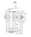
そこで、上記点を解決する本発明の装置の測定部断面図を図4に示す(光学センサ部は省略)。被検部である指の腹20が接触する部分には棒状部材(ブロック)21を配置し、棒状部材21の周囲は、熱伝導率が棒状部材21の熱伝導率より低い断熱材22で覆い囲む。こうすることで、棒状部材21以外へ流れる漏れ熱流量を低減できる。さらに、棒状部材21の指の腹20が接触する部分にサーミスタ23(温度T1)を、そして棒状部材21のもう一端にサーミスタ24(温度T2)を設置し、サーミスタ24を含む棒状部材21の一部分を、測定部内に設けたダクト25内に設置し、筐体26の外から室温の空気27をダクト内に設けたファン28で筐体26の内部へ導入し、サーミスタ24を含む棒状部材21の一部分に室温空気27を当てる構造とする。 Therefore, FIG. 4 shows a cross-sectional view of the measuring unit of the apparatus of the present invention that solves the above-mentioned points (the optical sensor unit is omitted). A rod-shaped member (block) 21 is arranged at a portion where the
これは、図1に示す、温度T2と室温T4との間の熱抵抗R3を低減することを意味し、温度が定常になるまでの時間を短縮する効果がある。また、無侵襲血糖値測定装置100内に測定部以外の実装部品(半導体チップや表示部)から発生する熱が、測定部のサーミスタ23、24へあぶられ、測定値に悪影響を生じることも防止できる。なお図4では、室温空気27をファン28でダクト25に押し込み、筐体26の外へ排出する構造にしたが、それに限ったものではなく、室温空気27をファン28でダクト25を通じて、筐体26の外から吸込む構造もある。 This means that the thermal resistance R3 between the temperature T2 and the room temperature T4 shown in FIG. 1 is reduced, and has the effect of shortening the time until the temperature becomes steady. In addition, heat generated from mounting parts (semiconductor chip and display unit) other than the measurement unit in the non-invasive blood sugar
指の腹20を見通せる装置内部の位置に赤外線レンズ29が置かれ、赤外線レンズ29の下方に赤外線透過窓30を介して焦電検出器31が配置されている。また、焦電検出器31に近接して別のサーミスタ32が設置されている。これらにより、輻射温度T3及び室温T4を測定する。 An
図5に、温度T1とT2の温度上昇曲線の一例を示す(室温T4=20℃)。横軸が時間で、縦軸が温度である。図中、実線が温度T1、破線が温度T2で、●が室温下での自然冷却、○が図4で述べた、ファンによる強制冷却の場合を示す。 FIG. 5 shows an example of temperature rise curves of temperatures T1 and T2 (room temperature T4 = 20 ° C.). The horizontal axis is time, and the vertical axis is temperature. In the figure, the solid line is the temperature T1, the broken line is the temperature T2, the black circle is the natural cooling at room temperature, and the black circle is the forced cooling by the fan described in FIG.
温度T1、T2は時間の経過と共に上昇し、ある一定値に飽和する。飽和した温度T1とT2を測定することで、上式(1)から熱抵抗R1を算出するが、自然冷却の場合、飽和するまでの時間は120秒程度を要するのに対し、強制冷却の場合では約60秒と自然冷却の場合と比して半分となり、測定時間を大幅に短縮できることが分る。 The temperatures T1 and T2 rise with time and saturate to a certain value. By measuring the saturated temperatures T1 and T2, the thermal resistance R1 is calculated from the above equation (1). In the case of natural cooling, it takes about 120 seconds to saturate, whereas in the case of forced cooling So, it is about 60 seconds, which is half that of the case of natural cooling, and it can be seen that the measurement time can be greatly shortened.
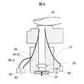
図6に、本発明の第二実施例を示す。この構成は、測定環境が空調風等により不安定な場合や、更なる高精度、また更に短時間で測定する必要のある場合に有効である。すなわち、サーミスタ24側の棒状部材21の一部分を、熱伝導率の非常に高い材料、例えば銅やアルミでできた冷却側ヒートシンク40に接続させる。そしてヒートシンクを一定温度に冷却するためのペルチェ素子41を冷却側ヒートシンク40と接続させる。さらにペルチェ素子41のもう一方側には放熱側ヒートシンク42を接続させ、放熱側ヒートシンク42にヒートパイプ43を接続する。ヒートパイプ43にフィン44を設け、そのフィン44を無侵襲血糖値測定装置100内に設けたダクト45内に配置する。そしてファン46を用いて、外気をダクト45に導入し、フィン44を冷却する。一方、ペルチェ素子41は、他から影響を受けずに室温を検知する温度計(図示せず)からの信号で、その室温と同じかつ一定になるよう制御され、温度T2を安定させる。こうすることで、外部環境が変動する場所でも、温度T1、T2を短時間で高精度に測れる利点を有する。 FIG. 6 shows a second embodiment of the present invention. This configuration is effective when the measurement environment is unstable due to air-conditioning air or the like, or when it is necessary to perform measurement with higher accuracy and in a shorter time. That is, a part of the rod-
上記説明は、熱抵抗R3を、図4の実施例より、さらに低減する内容であるが、この実施例の別の効果として、図7に示す温度T1の温度上昇曲線において(横軸は時間、縦軸は初期状態からの温度差で、実線が熱抵抗R3の大きい場合、また破線が熱抵抗R3の小さい場合、そして、○が各々の温度上昇曲線を指数関数で近似した場合を示す)、熱抵抗R3を低減することで、指の腹20を棒状部材21に置いてからの温度上昇曲線が指数関数近似に近づくことが分る。従って、指の腹20を温度T1が飽和するまで棒状部材21に置かなくても、ある程度の時間を経た温度上昇曲線を用いて温度T1の飽和値を指数関数で精度良く推算することが可能となる。 The above description is the content of further reducing the thermal resistance R3 from the embodiment of FIG. 4, but as another effect of this embodiment, in the temperature rise curve of the temperature T1 shown in FIG. The vertical axis is the temperature difference from the initial state, where the solid line shows a large thermal resistance R3, the broken line shows a small thermal resistance R3, and ◯ shows the case where each temperature rise curve is approximated by an exponential function) By reducing the thermal resistance R3, it can be seen that the temperature rise curve after placing the
また、ヒートパイプ43の形状を任意に変えることで、ファン46の設置場所を任意に変えることができ、測定部のレイアウトの自由度も増やすことができる。 Further, by arbitrarily changing the shape of the
図8に本発明の第三実施例を示す。これは、ペルチェ素子41の放熱に液冷構造を用いたものである。即ち、ペルチェ素子41の放熱側に液冷ジャケット50を接続させ、ポンプ51、ラジエータ52をチューブ53で各々直列に接続して液冷循環とする。こうすることで、ポンプ51やラジエータ52の配置の自由度を増すことができる。 FIG. 8 shows a third embodiment of the present invention. This uses a liquid cooling structure for heat dissipation of the
次に光学測定について述べる。図3に示す光学センサ部18は、酸素供給量を求めるために必要なヘモグロビン濃度とヘモグロビン酸素飽和度とを測定するためのものである。ヘモグロビン濃度とヘモグロビン酸素飽和度を測定するには最低2波長での吸光度測定が必要であり、図9は2個の光源62、63と1個の検出器64によって2波長測定を行うための構成例を示している。 Next, optical measurement will be described. The
光学センサ部18には、2個の光ファイバー60、61の端部が位置する。光ファイバー60は光照射用の光ファイバーであり、光ファイバー61は受光用の光ファイバーである。光ファイバー60は支線となるファイバー60a、60bにつながり、それらの末端には2つの波長の発光ダイオード62、63が配されている。受光用光ファイバー61の末端には、フォトダイオード64が配されている。発光ダイオード62は波長810nmの光を出し、発光ダイオード63は波長950nmの光を出す。波長810nmは、酸素結合型ヘモグロビンと還元型(脱酸素)型ヘモグロビンのモル吸光係数が等しくなる等吸光波長であり、波長950nmは酸素結合型ヘモグロビンと還元型ヘモグロビンのモル吸光係数の差が大きい波長である。 The ends of the two
2個の発光ダイオード62、63は時分割的に発光し、発光ダイオード62、63から発生された光は光照射用光ファイバー60から被検者の指の腹20に照射される。指に照射された光は指の腹20の皮膚で反射し、受光用光ファイバー61に入射してフォトダイオード64によって検出される。指に照射された光が指の皮膚で反射されるとき、一部の光は皮膚を通して組織内部に侵入し、毛細血管を流れる血液中のヘモグロビンによる吸収を受ける。フォトダイオード64による測定データは反射率Rであり、吸光度は近似的にlog(1/R)で計算される。波長810nmと波長950nmの光について各々照射を行い、各々についてRを測定し、log(1/R)を求めることにより、波長810nmの吸光度A1と波長950nmの吸光度A2が測定される。 The two
還元型ヘモグロビン濃度を[Hb]、酸素結合型ヘモグロビン濃度を[HbO2]とすると、吸光度A1および吸光度A2は次式(2)で表される。 Assuming that the reduced hemoglobin concentration is [Hb] and the oxygen-binding hemoglobin concentration is [HbO2], the absorbance A1 and absorbance A2 are expressed by the following formula (2).
AHb(810nm)とAHb(950nm)、AHbO2(810nm)とAHbO2(950nm)はそれぞれ還元型ヘモグロビン、酸素結合型ヘモグロビンのモル吸光係数であり各波長で既知である。aは比例係数である。ヘモグロビン濃度[Hb]+[HbO2]、ヘモグロビン酸素飽和度[HbO2]/([Hb]+[HbO2])は上式から次のように求められる。 AHb (810 nm) and AHb (950 nm), AHbO2 (810 nm) and AHbO2 (950 nm) are the molar extinction coefficients of reduced hemoglobin and oxygen-binding hemoglobin, respectively, and are known at each wavelength. a is a proportionality coefficient. The hemoglobin concentration [Hb] + [HbO2] and the hemoglobin oxygen saturation [HbO2] / ([Hb] + [HbO2]) are obtained from the above equation as follows.
なお、ここでは2波長による吸光度測定によってヘモグロビン濃度とヘモグロビン酸素飽和度を測定する例について説明したが、3波長以上で吸光度を測定することによって、妨害成分の影響を低減し測定精度を高めることも可能である。 Although an example of measuring hemoglobin concentration and hemoglobin oxygen saturation by measuring absorbance at two wavelengths has been described here, measuring the absorbance at three wavelengths or more can reduce the influence of interference components and increase the measurement accuracy. Is possible.
図10は、装置内におけるデータ処理の流れを示す概念図である。本例の装置には、サーミスタ23、サーミスタ24、焦電検出器31、サーミスタ32、フォトダイオード64からなる5個のセンサがある。フォトダイオード64では波長810nmの吸光度と波長950nmの吸光度を測定するため、装置には6種類の測定値が入力されることになる。 FIG. 10 is a conceptual diagram showing the flow of data processing in the apparatus. In the apparatus of this example, there are five sensors including a
5種類のアナログ信号は、それぞれA1〜A5の増幅器を経由して、AD1〜AD5のアナログ・デジタル変換器によってデジタル変換される。デジタル変換された値からパラメータxi(i=1、2、3、4、5)が計算される。xiを具体的に表記すると以下のとおりとなる(a1〜a5は比例係数)。 The five types of analog signals are converted into digital signals by analog / digital converters AD1 to AD5 via amplifiers A1 to A5, respectively. Parameters xi (i = 1, 2, 3, 4, 5) are calculated from the digitally converted values. Specifically, xi is expressed as follows (a1 to a5 are proportional coefficients).
つづいて、実際の多数の健常者および糖尿病患者のデータから得られたパラメータxiの平均値と標準偏差から正規化パラメータを算出する。各パラメータxiから正規化パラメータXi(i=1、2、3、4、5)を次の式で計算する。 Subsequently, a normalization parameter is calculated from the average value and standard deviation of the parameter xi obtained from the data of a large number of actual healthy persons and diabetic patients. A normalization parameter Xi (i = 1, 2, 3, 4, 5) is calculated from each parameter xi by the following formula.
前述の5つの正規化パラメータをもって、最終的な表示を行うためのグルコース濃度への変換計算が行われる。処理計算に必要なプログラムは、装置に組み込まれたマイクロプロセッサに内蔵されたROMに記憶されている。また、処理計算に必要なメモリー領域は、同様に装置に組み込まれているRAMに確保される。計算処理された結果は、液晶表示部に表示される。 With the above-mentioned five normalization parameters, conversion calculation to glucose concentration for final display is performed. A program necessary for processing calculation is stored in a ROM built in a microprocessor incorporated in the apparatus. Similarly, a memory area necessary for processing calculation is secured in a RAM incorporated in the apparatus. The result of the calculation process is displayed on the liquid crystal display unit.
ROMには処理計算に必要なプログラム構成要素として、特にグルコース濃度Cを求めるための関数が入っている。この関数は以下のように定められたものである。まず、Cは以下の式(6)で表現される。ai(i=0、1、2、3、4、5)は、複数の測定データから前もって決定されている。aiを求める手順は以下の通りである。
(1) 正規化パラメータとグルコース濃度Cの関係を示す重回帰式を作成する。
(2) 最小二乗法によって得られた式から正規化パラメータに関する正規方程式(連立方程式)を求める。
(3) 正規方程式から係数ai(i=0、1、2、3、4、5)の値を求め、重回帰式に代入する。
初めに、グルコース濃度Cと正規化パラメータX1、X2、X3、X4、X5の関係を示す次の回帰式(6)を作る。The ROM contains a function for obtaining the glucose concentration C as a program component necessary for processing calculation. This function is defined as follows. First, C is expressed by the following equation (6). ai (i = 0, 1, 2, 3, 4, 5) is determined in advance from a plurality of measurement data. The procedure for obtaining ai is as follows.
(1) Create a multiple regression equation showing the relationship between the normalization parameter and glucose concentration C.
(2) Obtain a normal equation (simultaneous equation) for the normalization parameter from the formula obtained by the least square method.
(3) Obtain the value of coefficient ai (i = 0, 1, 2, 3, 4, 5) from the normal equation and substitute it into the multiple regression equation.
First, the following regression equation (6) showing the relationship between the glucose concentration C and the normalization parameters X1, X2, X3, X4, and X5 is created.
つづいて、酵素電極法によるグルコース濃度測定値Ciとの誤差が最小になるような重回帰式を求めるため、最小二乗法を用いる。残差の二乗和をDとすると、Dは次式で表される。 Subsequently, the least square method is used to obtain a multiple regression equation that minimizes an error from the glucose concentration measurement value Ci by the enzyme electrode method. If the residual sum of squares is D, D is expressed by the following equation.
残差の二乗和Dが最小になるのは、式(7)をa0、a2、…、a5で偏微分してゼロとなるときなので、次式(8)が得られる。 The residual sum of squares D is minimized when equation (7) is partially differentiated by a0, a2,..., A5 to become zero, and the following equation (8) is obtained.
C、X1〜X5の平均値をCmean、X1mean〜X5meanとするとXimean=0(i=1〜5)であるので、式(6)から式(9)が得られる。 When the average values of C and X1 to X5 are Cmean and X1mean to X5mean, Ximean = 0 (i = 1 to 5), and therefore, Expression (9) is obtained from Expression (6).
また、正規化パラメータ間の変動・共変動は、式(10)で表され、正規化パラメータXi(i=1〜5)とCとの共変動は式(11)で表される。 Further, the fluctuation / covariation between the normalization parameters is expressed by Expression (10), and the covariation between the normalization parameter Xi (i = 1 to 5) and C is expressed by Expression (11).
式(9)、式(10)、式(11)を式(8)に代入して整理すると、連立方程式(正規方程式)(12)が得られ、これを解くことでa1〜a5が求まる。 By substituting Equation (9), Equation (10), and Equation (11) into Equation (8) and rearranging, simultaneous equations (normal equations) (12) are obtained, and a1 to a5 are obtained by solving these equations.
定数項a0は式(9)を用いて求める。以上で求めたai(i=0、1、2、3、4、5)は装置製造時にROMに格納されている。装置による実際の測定では、測定値から求めた正規化パラメータX1〜X5を回帰式(6)に代入することで、グルコース濃度Cが算出される。 The constant term a0 is obtained using equation (9). The above obtained ai (i = 0, 1, 2, 3, 4, 5) is stored in the ROM when the apparatus is manufactured. In actual measurement by the apparatus, the glucose concentration C is calculated by substituting the normalization parameters X1 to X5 obtained from the measurement values into the regression equation (6).
次にグルコース濃度の算出過程の具体例を示す。予め健常者および糖尿病患者に対して測定した多数のデータから式(6)の係数が決められており、マイクロプロセッサのROMには下記のグルコース濃度の算出式が格納されている。 Next, a specific example of the glucose concentration calculation process is shown. The coefficient of equation (6) is determined from a large number of data measured in advance for healthy individuals and diabetic patients, and the following formula for calculating the glucose concentration is stored in the ROM of the microprocessor.
X1〜X5はパラメータx1〜x5を正規化したものである。パラメータの分布が正規分布であると仮定すると、正規化パラメータの95%は−2〜+2の間の値をとる。 X1 to X5 are normalized parameters x1 to x5. Assuming that the parameter distribution is a normal distribution, 95% of the normalized parameters take values between -2 and +2.
健常者の測定値の一例として、正規化パラメータX1=+0.10、X2=−0.02、X3=+0.04、X4=−0.20、X5=+0.20 を上記の式に代入するとC=94mg/dlとなる。 As an example of the measured value of a healthy person, substituting the normalization parameters X1 = + 0.10, X2 = −0.02, X3 = + 0.04, X4 = −0.20, X5 = + 0.20 into the above formula, C = 94 mg / dl.
また、糖尿病患者の測定値の一例として、正規化パラメータX1=−1.10、X2=+0.10、X3=−0.84、X4=−1.04、X5=−0.20 を上記の式に代入するとC=221mg/dlとなる。 In addition, as an example of the measured value of a diabetic patient, substituting the normalization parameters X1 = −1.10, X2 = + 0.10, X3 = −0.84, X4 = −1.04, X5 = −0.20 into the above formula, C = 221 mg / dl.
従来の測定方法である、採血によって得た血液を試薬と反応させ、この反応によって発生した電子量を測定して血糖値を測定する酵素電極法による測定結果と本発明の一実施例による測定結果について以下に述べる。健常者の測定値の一例として、酵素電極法によるグルコース濃度が89mg/dlのとき、同時刻に本法による測定から得た正規化パラメータX1=+0.10、X2=−0.02、X3=+0.04、X4=−0.20、X5=+0.20 を上記の式に代入するとC=94mg/dlとなる。また、糖尿病患者の測定値の例として、酵素電極法によるグルコース濃度が238mg/dlのとき、同時刻に本法による測定から得た正規化パラメータX1=−1.10、X2=+0.10、X3=−0.84、X4=−1.04、X5=−0.20 を上記の式に代入するとC=221mg/dlとなる。上記の結果より、本発明による方法によって、高精度でグルコース濃度を求められることが確認された。 Conventional measurement method, blood obtained by blood sampling is reacted with a reagent, the amount of electrons generated by this reaction is measured to measure the blood glucose level, and the measurement result according to one embodiment of the present invention Is described below. As an example of the measurement value of a healthy person, when the glucose concentration by the enzyme electrode method is 89 mg / dl, normalized parameters X1 = + 0.10, X2 = −0.02, X3 = + 0 obtained from the measurement by this method at the same time. Substituting 04, X4 = -0.20, X5 = +0.20 into the above equation gives C = 94 mg / dl. Moreover, as an example of the measured value of the diabetic patient, when the glucose concentration by the enzyme electrode method is 238 mg / dl, the normalization parameters X1 = −1.10, X2 = + 0.10, X3 = Substituting -0.84, X4 = -1.04, X5 = -0.20 into the above equation gives C = 221 mg / dl. From the above results, it was confirmed that the glucose concentration can be determined with high accuracy by the method according to the present invention.
図11は、縦軸を本法によるグルコース濃度の算出値、横軸を酵素電極法によるグルコース濃度の測定値として、複数の患者に対してそれぞれの測定値をプロットした図である。本法の様に酸素供給量・血流量を測定することで良好な相関が得られる。 FIG. 11 is a diagram in which measured values are plotted for a plurality of patients, with the vertical axis representing the glucose concentration calculated by this method and the horizontal axis representing the glucose concentration measured by the enzyme electrode method. Good correlation can be obtained by measuring oxygen supply and blood flow as in this method.
図12に装置の操作手順を示す。操作部のボタンを押し装置の電源を入れると、液晶表示器に「ウォーミングアップ」が表示され、装置内の電子回路がウォーミングアップされる。同時に、チェックプログラムが作動し、電子回路を自動的にチェックする。「ウォーミングアップ」が終了すると、液晶表示部に「指を置いてください」と表示される。指置き部に指を置くと、液晶表示部にカウントダウンが表示される。カウントダウンが終了すると、液晶表示部に「指を離してください」と表示される。指置き部から指を離すと、液晶表示部に「データ処理中」が表示される。その後、液晶表示部に血糖値が表示される。この時点で、表示された血糖値は、日時・時間とともにICカードに記憶される。表示された血糖値を読み取ったら、操作部のボタンを押す。装置は、約1分後に次の測定を待つ「指を置いてください」が液晶表示部に表示された状態になる。 FIG. 12 shows the operation procedure of the apparatus. When the button of the operation unit is pressed and the apparatus is turned on, “warming up” is displayed on the liquid crystal display, and the electronic circuit in the apparatus is warmed up. At the same time, a check program runs and automatically checks the electronic circuit. When “warming up” is completed, “Place your finger” is displayed on the LCD. When a finger is placed on the finger placement unit, a countdown is displayed on the liquid crystal display unit. When the countdown is finished, “Please release your finger” is displayed on the LCD. When the finger is removed from the finger placement unit, “data processing in progress” is displayed on the liquid crystal display unit. Thereafter, the blood glucose level is displayed on the liquid crystal display unit. At this time, the displayed blood glucose level is stored in the IC card together with the date / time. After reading the displayed blood glucose level, press the button on the operation unit. After about 1 minute, the device waits for the next measurement and “Place your finger” is displayed on the liquid crystal display.
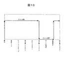
なお、測定時間中は、常に温度T2を冷却しているのが望ましいが、電池で長時間駆動させる等の都合で、装置の省電力化が必要な場合は、図12で述べた操作手順に沿ってファン動作のオンオフ制御を行っても良い。図13にファン動作のシーケンスを示す。横軸が図12で述べた操作手順である。「開始」から「指を離して下さい」までは、ファンのオン動作が必要であるが、「指を離して下さい」から「結果表示」までは測定していないため、ファンをオフさせる。そして「結果表示」後、再び測定に入るまでにファンをオンさせ、温度T2を初期の状態に素早く戻す。こうすることで、ファン動作をオフさせる分、装置の省電力が図れる。 Note that it is desirable that the temperature T2 is always cooled during the measurement time. However, if it is necessary to save the power of the apparatus due to, for example, driving with a battery for a long time, the operation procedure described in FIG. Along with this, the fan operation may be controlled on and off. FIG. 13 shows a sequence of fan operation. The horizontal axis is the operation procedure described in FIG. It is necessary to turn on the fan from “Start” to “Release finger”. However, since the measurement is not performed from “Release finger” to “Display result”, the fan is turned off. After the “result display”, the fan is turned on before the measurement is started again, and the temperature T2 is quickly returned to the initial state. In this way, the power consumption of the apparatus can be reduced by turning off the fan operation.
11…操作部、12…測定部、13…表示部、14…カバー、15…指置き部、16…輻射温度センサ部の開口端、17…接触温度センサ部、18…光学センサ部、20…指の腹、21…棒状部材、22…断熱材、23、24…サーミスタ、25…ダクト、26…筐体、27…室温空気、28…ファン、29…赤外線レンズ、30…赤外線透過窓、31…焦電検出器、32…サーミスタ、40…冷却側ヒートシンク、41…ペルチェ素子、42…放熱側ヒートシンク、43…ヒートパイプ、44…フィン、45…ダクト、46…ファン、50…液冷ジャケット、51…ポンプ、52…ラジエータ、53…チューブ、60…光ファイバー、61…光ファイバー、62…発光ダイオード、63…発光ダイオード、64…フォトダイオードDESCRIPTION OF
Claims (8)
Translated fromJapanese一端に体表面接触部を有する熱伝導部材と、
前記体表面からの輻射熱を測定する輻射熱検出器と、
前記熱伝導部材の前記体表面接触部に隣接して設けられた第1の温度検出器と、
前記熱伝導部材の他端に隣接して設けられた第2の温度検出器と、
前記熱伝導部材の他端側を冷却する冷却手段と、
前記体表面接触部に向けて少なくとも2つの異なる波長の光を照射する光源と、
前記光が前記体表面で反射されて生じる反射光を検出する光検出器と、
前記第1の温度検出器、前記第2の温度検出器、前記環境温度検出器、前記輻射熱検出器及び前記光検出器各々の出力を各々パラメータに変換する変換部と、前記パラメータと血糖値との関係を予め記憶し、前記パラメータを前記関係に適用して血糖値を算出する処理部とを有する演算部と、
前記演算部から出力される結果を表示する表示部とを備えることを特徴とする血糖値測定装置。An environmental temperature detector for measuring the environmental temperature;
A heat conducting member having a body surface contact portion at one end;
A radiant heat detector for measuring radiant heat from the body surface;
A first temperature detector provided adjacent to the body surface contact portion of the heat conducting member;
A second temperature detector provided adjacent to the other end of the heat conducting member;
A cooling means for cooling the other end of the heat conducting member;
A light source that emits light of at least two different wavelengths toward the body surface contact portion;
A photodetector for detecting reflected light generated by the light reflected from the body surface;
A conversion unit that converts each output of the first temperature detector, the second temperature detector, the environmental temperature detector, the radiant heat detector, and the light detector into a parameter; the parameter and a blood glucose level; And a processing unit that calculates a blood sugar level by applying the parameter to the relationship,
A blood glucose level measuring apparatus comprising: a display unit that displays a result output from the arithmetic unit.
Priority Applications (1)
| Application Number | Priority Date | Filing Date | Title |
|---|---|---|---|
| JP2005015717AJP2006198321A (en) | 2005-01-24 | 2005-01-24 | Blood glucose level measuring device |
Applications Claiming Priority (1)
| Application Number | Priority Date | Filing Date | Title |
|---|---|---|---|
| JP2005015717AJP2006198321A (en) | 2005-01-24 | 2005-01-24 | Blood glucose level measuring device |
Publications (1)
| Publication Number | Publication Date |
|---|---|
| JP2006198321Atrue JP2006198321A (en) | 2006-08-03 |
Family
ID=36956811
Family Applications (1)
| Application Number | Title | Priority Date | Filing Date |
|---|---|---|---|
| JP2005015717APendingJP2006198321A (en) | 2005-01-24 | 2005-01-24 | Blood glucose level measuring device |
Country Status (1)
| Country | Link |
|---|---|
| JP (1) | JP2006198321A (en) |
Cited By (15)
| Publication number | Priority date | Publication date | Assignee | Title |
|---|---|---|---|---|
| JP2010022723A (en)* | 2008-07-23 | 2010-02-04 | Osaka Univ | Thermometric conductivity measuring instrument, skin tissue blood circulation evaluation device and decubitus diagnostic device |
| JP2011024698A (en)* | 2009-07-23 | 2011-02-10 | Hitachi Media Electoronics Co Ltd | Blood sugar level measuring instrument |
| JP2011526819A (en)* | 2008-07-03 | 2011-10-20 | マシモ・ラボラトリーズ・インコーポレイテッド | Protrusions, heat sinks, and shielding to improve spectroscopic analysis of blood components |
| JP2012019834A (en)* | 2010-07-12 | 2012-02-02 | Seiko Epson Corp | Concentration determination apparatus, probe, concentration determination method, and program |
| CN102551733A (en)* | 2012-02-08 | 2012-07-11 | 北京三联永汇科技有限公司 | Heat conduction device and non-invasive blood glucose detector probe with same |
| JP2015221209A (en)* | 2014-05-22 | 2015-12-10 | エンパイア テクノロジー ディベロップメント エルエルシー | Device and method for measuring skin moisture |
| US9464983B2 (en) | 2010-07-12 | 2016-10-11 | Seiko Epson Corporation | Concentration determination apparatus, probe, concentration determination method, and program |
| JPWO2015141510A1 (en)* | 2014-03-20 | 2017-04-06 | パナソニックヘルスケアホールディングス株式会社 | Biological information measuring device and control method of biological information measuring device |
| US9668680B2 (en) | 2009-09-03 | 2017-06-06 | Masimo Corporation | Emitter driver for noninvasive patient monitor |
| JP2019012027A (en)* | 2017-06-30 | 2019-01-24 | 株式会社テクノ・コモンズ | Biological data measuring device |
| US10258266B1 (en) | 2008-07-03 | 2019-04-16 | Masimo Corporation | Multi-stream data collection system for noninvasive measurement of blood constituents |
| WO2021171831A1 (en)* | 2020-02-28 | 2021-09-02 | ソニーグループ株式会社 | Biological information acquisition device, biological information acquisition system, and biological information acquisition method |
| JP2021191434A (en)* | 2017-11-30 | 2021-12-16 | 株式会社テクノ・コモンズ | Biometric data measuring device |
| US12114974B2 (en) | 2020-01-13 | 2024-10-15 | Masimo Corporation | Wearable device with physiological parameters monitoring |
| US12336796B2 (en) | 2021-07-13 | 2025-06-24 | Masimo Corporation | Wearable device with physiological parameters monitoring |
- 2005
- 2005-01-24JPJP2005015717Apatent/JP2006198321A/enactivePending
Cited By (53)
| Publication number | Priority date | Publication date | Assignee | Title |
|---|---|---|---|---|
| US10624563B2 (en) | 2008-07-03 | 2020-04-21 | Masimo Corporation | Multi-stream data collection system for noninvasive measurement of blood constituents |
| US10588554B2 (en) | 2008-07-03 | 2020-03-17 | Masimo Corporation | Multi-stream data collection system for noninvasive measurement of blood constituents |
| JP2011526819A (en)* | 2008-07-03 | 2011-10-20 | マシモ・ラボラトリーズ・インコーポレイテッド | Protrusions, heat sinks, and shielding to improve spectroscopic analysis of blood components |
| US12036009B1 (en) | 2008-07-03 | 2024-07-16 | Masimo Corporation | User-worn device for noninvasively measuring a physiological parameter of a user |
| US12023139B1 (en) | 2008-07-03 | 2024-07-02 | Masimo Corporation | User-worn device for noninvasively measuring a physiological parameter of a user |
| US11751773B2 (en) | 2008-07-03 | 2023-09-12 | Masimo Corporation | Emitter arrangement for physiological measurements |
| US10631765B1 (en) | 2008-07-03 | 2020-04-28 | Masimo Corporation | Multi-stream data collection system for noninvasive measurement of blood constituents |
| US11642036B2 (en) | 2008-07-03 | 2023-05-09 | Masimo Corporation | User-worn device for noninvasively measuring a physiological parameter of a user |
| US11642037B2 (en) | 2008-07-03 | 2023-05-09 | Masimo Corporation | User-worn device for noninvasively measuring a physiological parameter of a user |
| US11638532B2 (en) | 2008-07-03 | 2023-05-02 | Masimo Corporation | User-worn device for noninvasively measuring a physiological parameter of a user |
| US11484229B2 (en) | 2008-07-03 | 2022-11-01 | Masimo Corporation | User-worn device for noninvasively measuring a physiological parameter of a user |
| US11484230B2 (en) | 2008-07-03 | 2022-11-01 | Masimo Corporation | User-worn device for noninvasively measuring a physiological parameter of a user |
| US11426103B2 (en) | 2008-07-03 | 2022-08-30 | Masimo Corporation | Multi-stream data collection system for noninvasive measurement of blood constituents |
| US10258266B1 (en) | 2008-07-03 | 2019-04-16 | Masimo Corporation | Multi-stream data collection system for noninvasive measurement of blood constituents |
| US10258265B1 (en) | 2008-07-03 | 2019-04-16 | Masimo Corporation | Multi-stream data collection system for noninvasive measurement of blood constituents |
| US10292628B1 (en) | 2008-07-03 | 2019-05-21 | Masimo Corporation | Multi-stream data collection system for noninvasive measurement of blood constituents |
| US10299708B1 (en) | 2008-07-03 | 2019-05-28 | Masimo Corporation | Multi-stream data collection system for noninvasive measurement of blood constituents |
| US10335068B2 (en) | 2008-07-03 | 2019-07-02 | Masimo Corporation | Multi-stream data collection system for noninvasive measurement of blood constituents |
| US10376191B1 (en) | 2008-07-03 | 2019-08-13 | Masimo Corporation | Multi-stream data collection system for noninvasive measurement of blood constituents |
| US10376190B1 (en) | 2008-07-03 | 2019-08-13 | Masimo Corporation | Multi-stream data collection system for noninvasive measurement of blood constituents |
| US10582886B2 (en) | 2008-07-03 | 2020-03-10 | Masimo Corporation | Multi-stream data collection system for noninvasive measurement of blood constituents |
| US10702194B1 (en) | 2008-07-03 | 2020-07-07 | Masimo Corporation | Multi-stream data collection system for noninvasive measurement of blood constituents |
| US10588553B2 (en) | 2008-07-03 | 2020-03-17 | Masimo Corporation | Multi-stream data collection system for noninvasive measurement of blood constituents |
| US10610138B2 (en) | 2008-07-03 | 2020-04-07 | Masimo Corporation | Multi-stream data collection system for noninvasive measurement of blood constituents |
| US10617338B2 (en) | 2008-07-03 | 2020-04-14 | Masimo Corporation | Multi-stream data collection system for noninvasive measurement of blood constituents |
| US10624564B1 (en) | 2008-07-03 | 2020-04-21 | Masimo Corporation | Multi-stream data collection system for noninvasive measurement of blood constituents |
| US10945648B2 (en) | 2008-07-03 | 2021-03-16 | Masimo Corporation | User-worn device for noninvasively measuring a physiological parameter of a user |
| US11647914B2 (en) | 2008-07-03 | 2023-05-16 | Masimo Corporation | User-worn device for noninvasively measuring a physiological parameter of a user |
| US10912500B2 (en) | 2008-07-03 | 2021-02-09 | Masimo Corporation | Multi-stream data collection system for noninvasive measurement of blood constituents |
| US10702195B1 (en) | 2008-07-03 | 2020-07-07 | Masimo Corporation | Multi-stream data collection system for noninvasive measurement of blood constituents |
| US10709366B1 (en) | 2008-07-03 | 2020-07-14 | Masimo Corporation | Multi-stream data collection system for noninvasive measurement of blood constituents |
| US10743803B2 (en) | 2008-07-03 | 2020-08-18 | Masimo Corporation | Multi-stream data collection system for noninvasive measurement of blood constituents |
| US10758166B2 (en) | 2008-07-03 | 2020-09-01 | Masimo Corporation | Multi-stream data collection system for noninvasive measurement of blood constituents |
| US10912502B2 (en) | 2008-07-03 | 2021-02-09 | Masimo Corporation | User-worn device for noninvasively measuring a physiological parameter of a user |
| US10912501B2 (en) | 2008-07-03 | 2021-02-09 | Masimo Corporation | User-worn device for noninvasively measuring a physiological parameter of a user |
| JP2010022723A (en)* | 2008-07-23 | 2010-02-04 | Osaka Univ | Thermometric conductivity measuring instrument, skin tissue blood circulation evaluation device and decubitus diagnostic device |
| JP2011024698A (en)* | 2009-07-23 | 2011-02-10 | Hitachi Media Electoronics Co Ltd | Blood sugar level measuring instrument |
| US9668680B2 (en) | 2009-09-03 | 2017-06-06 | Masimo Corporation | Emitter driver for noninvasive patient monitor |
| JP2012019834A (en)* | 2010-07-12 | 2012-02-02 | Seiko Epson Corp | Concentration determination apparatus, probe, concentration determination method, and program |
| US9464983B2 (en) | 2010-07-12 | 2016-10-11 | Seiko Epson Corporation | Concentration determination apparatus, probe, concentration determination method, and program |
| CN102551733A (en)* | 2012-02-08 | 2012-07-11 | 北京三联永汇科技有限公司 | Heat conduction device and non-invasive blood glucose detector probe with same |
| CN102551733B (en)* | 2012-02-08 | 2013-08-21 | 北京三联永汇科技有限公司 | Heat conduction device and non-invasive blood glucose detector probe with same |
| JPWO2015141510A1 (en)* | 2014-03-20 | 2017-04-06 | パナソニックヘルスケアホールディングス株式会社 | Biological information measuring device and control method of biological information measuring device |
| US10094804B2 (en) | 2014-03-20 | 2018-10-09 | Phc Holdings Corporation | Biological information measurement device and method for controlling biological information measurement device |
| JP2015221209A (en)* | 2014-05-22 | 2015-12-10 | エンパイア テクノロジー ディベロップメント エルエルシー | Device and method for measuring skin moisture |
| US9907506B2 (en) | 2014-05-22 | 2018-03-06 | Empire Technology Development Llc | Devices and methods for measuring skin moisture |
| JP2019012027A (en)* | 2017-06-30 | 2019-01-24 | 株式会社テクノ・コモンズ | Biological data measuring device |
| JP6999301B2 (en) | 2017-06-30 | 2022-01-18 | 株式会社テクノ・コモンズ | Biometric data measuring device |
| JP2021191434A (en)* | 2017-11-30 | 2021-12-16 | 株式会社テクノ・コモンズ | Biometric data measuring device |
| JP7213505B2 (en) | 2017-11-30 | 2023-01-27 | 株式会社テクノ・コモンズ | Biometric data measuring device |
| US12114974B2 (en) | 2020-01-13 | 2024-10-15 | Masimo Corporation | Wearable device with physiological parameters monitoring |
| WO2021171831A1 (en)* | 2020-02-28 | 2021-09-02 | ソニーグループ株式会社 | Biological information acquisition device, biological information acquisition system, and biological information acquisition method |
| US12336796B2 (en) | 2021-07-13 | 2025-06-24 | Masimo Corporation | Wearable device with physiological parameters monitoring |
Similar Documents
| Publication | Publication Date | Title |
|---|---|---|
| JP3566276B1 (en) | Blood glucose meter | |
| JP3590054B1 (en) | Blood glucose measurement device | |
| US7156810B2 (en) | Blood sugar level measuring method and apparatus | |
| JP3612324B1 (en) | Blood glucose level display method and apparatus | |
| US7215983B2 (en) | Blood sugar level measuring apparatus | |
| JP3566277B1 (en) | Blood glucose meter | |
| JP5216709B2 (en) | Blood glucose level measuring device | |
| JP2005230118A (en) | Blood glucose level measuring device | |
| JP2005230124A (en) | Blood glucose level measuring device | |
| JP2006115948A (en) | Blood glucose level measuring device | |
| JP2005237484A (en) | Blood glucose level measuring device | |
| JP2005095317A (en) | Optical measuring device and blood glucose level measuring device using the same | |
| JP3566278B1 (en) | Blood glucose meter | |
| JP2006198321A (en) | Blood glucose level measuring device | |
| JP3884036B2 (en) | Blood glucose level measuring device | |
| EP1774903A1 (en) | Metabolic rate measuring apparatus | |
| JP3868963B2 (en) | Blood glucose level measuring device | |
| JP2006094992A (en) | Blood glucose level measuring apparatus and blood glucose level measuring method | |
| JP3874743B2 (en) | Temperature measuring device | |
| JP2005160782A (en) | Blood glucose level measuring device | |
| JP2007105331A (en) | Metabolism measuring device | |
| JP3623498B6 (en) | Blood glucose level measuring device | |
| JP2006115947A (en) | Blood glucose level measuring device |