JP2006195569A - Memory unit - Google Patents
Memory unitDownload PDFInfo
- Publication number
- JP2006195569A JP2006195569AJP2005004299AJP2005004299AJP2006195569AJP 2006195569 AJP2006195569 AJP 2006195569AJP 2005004299 AJP2005004299 AJP 2005004299AJP 2005004299 AJP2005004299 AJP 2005004299AJP 2006195569 AJP2006195569 AJP 2006195569A
- Authority
- JP
- Japan
- Prior art keywords
- data
- grade
- semiconductor memory
- flash memory
- controller
- Prior art date
- Legal status (The legal status is an assumption and is not a legal conclusion. Google has not performed a legal analysis and makes no representation as to the accuracy of the status listed.)
- Pending
Links
Images


Classifications
- H—ELECTRICITY
- H04—ELECTRIC COMMUNICATION TECHNIQUE
- H04M—TELEPHONIC COMMUNICATION
- H04M1/00—Substation equipment, e.g. for use by subscribers
- H04M1/02—Constructional features of telephone sets
- H04M1/0202—Portable telephone sets, e.g. cordless phones, mobile phones or bar type handsets
- H04M1/0206—Portable telephones comprising a plurality of mechanically joined movable body parts, e.g. hinged housings
- H04M1/0208—Portable telephones comprising a plurality of mechanically joined movable body parts, e.g. hinged housings characterized by the relative motions of the body parts
- H04M1/0214—Foldable telephones, i.e. with body parts pivoting to an open position around an axis parallel to the plane they define in closed position
- H04M1/0216—Foldable in one direction, i.e. using a one degree of freedom hinge
- G—PHYSICS
- G06—COMPUTING OR CALCULATING; COUNTING
- G06F—ELECTRIC DIGITAL DATA PROCESSING
- G06F3/00—Input arrangements for transferring data to be processed into a form capable of being handled by the computer; Output arrangements for transferring data from processing unit to output unit, e.g. interface arrangements
- G06F3/06—Digital input from, or digital output to, record carriers, e.g. RAID, emulated record carriers or networked record carriers
- G06F3/0601—Interfaces specially adapted for storage systems
- G06F3/0628—Interfaces specially adapted for storage systems making use of a particular technique
- G06F3/0655—Vertical data movement, i.e. input-output transfer; data movement between one or more hosts and one or more storage devices
- G06F3/0656—Data buffering arrangements
- G—PHYSICS
- G06—COMPUTING OR CALCULATING; COUNTING
- G06F—ELECTRIC DIGITAL DATA PROCESSING
- G06F3/00—Input arrangements for transferring data to be processed into a form capable of being handled by the computer; Output arrangements for transferring data from processing unit to output unit, e.g. interface arrangements
- G06F3/06—Digital input from, or digital output to, record carriers, e.g. RAID, emulated record carriers or networked record carriers
- G06F3/0601—Interfaces specially adapted for storage systems
- G06F3/0602—Interfaces specially adapted for storage systems specifically adapted to achieve a particular effect
- G06F3/061—Improving I/O performance
- G06F3/0613—Improving I/O performance in relation to throughput
- G—PHYSICS
- G06—COMPUTING OR CALCULATING; COUNTING
- G06F—ELECTRIC DIGITAL DATA PROCESSING
- G06F3/00—Input arrangements for transferring data to be processed into a form capable of being handled by the computer; Output arrangements for transferring data from processing unit to output unit, e.g. interface arrangements
- G06F3/06—Digital input from, or digital output to, record carriers, e.g. RAID, emulated record carriers or networked record carriers
- G06F3/0601—Interfaces specially adapted for storage systems
- G06F3/0668—Interfaces specially adapted for storage systems adopting a particular infrastructure
- G06F3/0671—In-line storage system
- G06F3/0673—Single storage device
- G06F3/0679—Non-volatile semiconductor memory device, e.g. flash memory, one time programmable memory [OTP]
- G—PHYSICS
- G11—INFORMATION STORAGE
- G11C—STATIC STORES
- G11C7/00—Arrangements for writing information into, or reading information out from, a digital store
- G11C7/22—Read-write [R-W] timing or clocking circuits; Read-write [R-W] control signal generators or management
Landscapes
- Engineering & Computer Science (AREA)
- Theoretical Computer Science (AREA)
- Human Computer Interaction (AREA)
- Physics & Mathematics (AREA)
- General Engineering & Computer Science (AREA)
- General Physics & Mathematics (AREA)
- Signal Processing (AREA)
- Read Only Memory (AREA)
- Techniques For Improving Reliability Of Storages (AREA)
- Memory System (AREA)
Abstract
Description
Translated fromJapanese本発明は記憶装置に関し、例えば、パーソナルコンピュータやデジタルカメラ等の情報処理装置から供給されるデータを内部の半導体メモリに対して記憶するようになされた半導体記憶装置に適用して好適なものである。 The present invention relates to a storage device, and is suitable for application to a semiconductor storage device adapted to store data supplied from an information processing device such as a personal computer or a digital camera in an internal semiconductor memory. .
従来この種の半導体記憶装置は、パーソナルコンピュータやデジタルカメラ等に相当する情報処理装置に接続されると、この情報処理装置から供給される電力により、この情報処理装置から供給されるデータを内部の半導体メモリに書き込むデータ書込処理や、この情報処理装置から要求されるデータを内部の半導体メモリから読み出すデータ読出処理を実行するようになされている(例えば特許文献1参照)。
ところで、このような半導体記憶装置を接続した情報処理装置が、例えばその内部に設けられたバッテリから供給される電力により動作するデジタルカメラに相当する場合、この半導体記憶装置におけるデータ書込処理速度やデータ読出処理速度をある程度低下させることができれば、デジタルカメラの消費電力を低減させることができる等の効果を得ることができる。 By the way, when the information processing apparatus connected to such a semiconductor storage device corresponds to, for example, a digital camera that operates with electric power supplied from a battery provided therein, the data writing processing speed in the semiconductor storage device or If the data reading processing speed can be reduced to some extent, it is possible to obtain an effect that the power consumption of the digital camera can be reduced.
また、このような半導体記憶装置を接続した情報処理装置が、例えば家庭内の商用電源からの電源供給を受けて動作するパーソナルコンピュータに相当する場合、この半導体記憶装置におけるデータ書込処理速度やデータ読出処理速度を上げることができれば、データ書込処理やデータ読出処理の処理時間を短縮することができる等の効果を得ることができる。 In addition, when an information processing apparatus connected to such a semiconductor storage device corresponds to, for example, a personal computer that operates by receiving power supply from a commercial power source in the home, the data writing processing speed and data in the semiconductor storage device If the reading processing speed can be increased, it is possible to obtain effects such as shortening the processing time of data writing processing and data reading processing.
このように半導体記憶装置が利用される状況に応じて、この半導体記憶装置のデータ書込処理速度やデータ読出処理速度を変更することができれば、利便性を格段と向上させることができると考えられる。 If the data write processing speed and data read processing speed of the semiconductor memory device can be changed in accordance with the situation in which the semiconductor memory device is used in this way, it is considered that convenience can be remarkably improved. .
さらに、このような半導体記憶装置では、読み書きされるデータの種類(動画像データや音楽(音声)データ)に応じて、最低のデータ書込処理速度や最低のデータ読出処理速度を保障することができれば、コマ落ちしないで動画像データを録画させることができるといった効果や、音楽(音声)データを切れ目なく録音/再生させることができるといった効果等を得ることができる。 Further, in such a semiconductor memory device, it is possible to guarantee the minimum data writing processing speed and the minimum data reading processing speed according to the type of data to be read / written (moving image data or music (voice) data). If possible, it is possible to obtain an effect that video data can be recorded without dropping frames, an effect that music (voice) data can be recorded / reproduced without breaks, and the like.
本発明は以上の点を考慮してなされたもので、データ書込処理速度やデータ読出処理速度を適宜変更することができる記憶装置、並びに、データ書込処理速度やデータ読出処理速度を保障することができる記憶装置を提案しようとするものである。 The present invention has been made in consideration of the above points, and guarantees the storage device capable of appropriately changing the data writing processing speed and the data reading processing speed, and the data writing processing speed and the data reading processing speed. It is intended to propose a storage device that can be used.
かかる課題を解決するため本発明においては、記憶装置において、データを記憶する複数のメモリ手段と、メモリ手段を制御する制御手段とを設け、制御手段は、供給された指定信号により指定された個数のメモリ手段に対して、接続している接続先装置から供給されたデータを書き込むデータ書込処理又は接続先装置から要求されたデータを読み出すデータ読出処理を並列的に実行するようにした。 In order to solve such a problem, in the present invention, in the storage device, a plurality of memory means for storing data and a control means for controlling the memory means are provided, and the control means is the number designated by the supplied designation signal. A data writing process for writing data supplied from the connected destination device or a data reading process for reading data requested from the destination device is executed in parallel with the memory means.
この結果この記憶装置によれば、指定信号によって指定するメモリ手段の個数を変化させることにより、データ書込処理速度やデータ読出処理速度を適宜変更することができる。 As a result, according to this storage device, the data writing processing speed and the data reading processing speed can be appropriately changed by changing the number of memory means designated by the designation signal.
また本発明においては、記憶装置において、データを記憶する複数のメモリ手段と、メモリ手段を制御する制御手段と設け、接続している接続先装置から供給されたデータを書き込むデータ書込処理速度又は接続先装置から要求されたデータを読み出すデータ読出処理速度を保障するようにした In the present invention, in the storage device, a plurality of memory means for storing data and a control means for controlling the memory means are provided, and the data writing processing speed for writing the data supplied from the connected destination device or Ensured data read processing speed to read data requested from connected device
この結果この記憶装置によれば、最低のデータ書込処理速度や最低のデータ読出処理速度を保障することができるので、コマ落ちしないで動画像データを録画させることができるといった効果や、音楽(音声)データを切れ目なく録音/再生させることができるといった効果等を得ることができる。 As a result, according to this storage device, the minimum data writing processing speed and the minimum data reading processing speed can be ensured, so that moving image data can be recorded without dropping frames, music ( (Sound) Data can be recorded / reproduced without any interruption.
本発明によれば、指定信号によって指定するメモリ手段の個数を変化させることにより、データ書込処理速度やデータ読出処理速度を適宜変更することができる。また本発明によれば、データ書込処理速度やデータ読出処理速度を保障することができる According to the present invention, the data writing processing speed and the data reading processing speed can be appropriately changed by changing the number of memory means designated by the designation signal. Further, according to the present invention, the data writing processing speed and the data reading processing speed can be ensured.
以下図面について、本発明の一実施の形態を詳述する。 Hereinafter, an embodiment of the present invention will be described in detail with reference to the drawings.
(1)第1の実施の形態
図1において、1は全体として第1の実施の形態における半導体記憶装置を示し、この半導体記憶装置1は、例えばコネクタに相当する接続部(図中に明示せず)を有し、この接続部を介して情報処理装置側のPCIエキスプレス(PCI Express)バスに接続し、これによりPCIエキスプレス方式に基づいてこの情報処理装置とデータ通信するようになされている。(1) First Embodiment In FIG. 1,
ここでこのPCIエキスプレスとは、PCI−SIG(PCI Special Interest Group)においてその規格が策定管理されているものである。また本実施の形態の場合この半導体記憶装置1は、その外観がカード型に形成されており、例えばPCカードの大きさ/形状に類するものである。 Here, the PCI express is one whose standard is formulated and managed by PCI Special Interest Group (PCI-SIG). In the case of the present embodiment, the
この半導体記憶装置1は、データを記憶するためのフラッシュメモリ部2を有する。またこの半導体記憶装置1は、接続部を介して接続している情報処理装置からのデータをフラッシュメモリ部2に対して書き込むデータ書込処理及びこの情報処理装置から要求されたデータをフラッシュメモリ部2から読み出すデータ読出処理を実行するためのコントローラ3を有する。 The
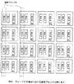
実際上このフラッシュメモリ部2は、データが記憶されるフラッシュメモリチップCPが複数接続されて構成されている。つまりこのフラッシュメモリ部2は、例えば図2に示すように、コントローラ3から延長する第1データ伝送線L1、第2データ伝送線L2、第3データ伝送線L3、及び第4データ伝送線L4のそれぞれに対して、第1〜第4フラッシュメモリチップCPA0〜A3、第5〜第8フラッシュメモリチップCPB0〜B3、第9〜第12フラッシュメモリチップCPC0〜C3、及び第13〜第16フラッシュメモリチップCPD0〜D3が接続されて構成されている。In practice, the
またコントローラ3内部には、メインメモリ部4に格納されているファームウェア等に従ってコントローラ3全体を制御するようになされたCPU(Central Processing Unit)5が設けられている。またこのコントローラ3内部には、接続部を介して接続している情報処理装置とPCIエキスプレス方式に基づいてデータ通信するためのホストインターフェース部6が設けられている。 In addition, a CPU (Central Processing Unit) 5 is provided inside the
これによりこの半導体記憶装置1は、接続部を介して接続している情報処理装置からフラッシュメモリ部2に書き込むべき書込データが送信されると、当該送信された書込データをホストインターフェース部6により受信する。 As a result, when write data to be written to the
このホストインターフェース部6は、当該受信した書込データをコントローラ3内部に設けられたページバッファ部7に対して供給する。 The
このページバッファ部7は、ホストインターフェース部6からの書込データを一時蓄積すると共に、当該蓄積している書込データをコントローラ3内部に設けられたメモリインターフェース部8に対して適宜供給する。 The page buffer unit 7 temporarily stores the write data from the
このメモリインターフェース部8は、ページバッファ部7からの書込データをフラッシュメモリ部2に対して供給する。 The
このフラッシュメモリ部2におけるフラッシュメモリチップCPは、メモリインターフェース部8からの書込データをその内部に設けられたキャッシュに一時蓄積し、当該蓄積した書込データをその内部の記憶領域に順次記憶させる。 The flash memory chip CP in the
一方この半導体記憶装置1のコントローラ3は、接続部を介して接続している情報処理装置から、フラッシュメモリ部2に記憶されているデータを読み出すように命令されると、フラッシュメモリ部2におけるフラッシュメモリチップCPからデータを読み出し、当該読み出した読出データをPCIエキスプレス方式に基づいて情報処理装置に対して送信するようになされている。 On the other hand, when the
つまりこのコントローラ3内部のメモリインターフェース部8は、フラッシュメモリ部2から読み出された読出データを受信し、当該受信した読出データをページバッファ部7に対して供給する。 That is, the
このページバッファ部7は、メモリインターフェース部8から供給される読出データを一時蓄積すると共に、当該蓄積している読出データをホストインターフェース部6に対して適宜供給する。 The page buffer unit 7 temporarily stores the read data supplied from the
このホストインターフェース部6は、ページバッファ部7からの読出データをPCIエキスプレス方式に基づいて情報処理装置に対して送信する。 The
このようにしてこの半導体記憶装置1は、情報処理装置から送信された書込データをPCIエキスプレス方式に基づいて受信することができると共に、フラッシュメモリ部2から読み出した読出データをPCIエキスプレス方式に基づいて情報処理装置に対して送信することができる。 In this manner, the
ここで従来この種の半導体記憶装置は、情報処理装置とデータ通信するための通信端子数を増やす手法や、情報処理装置との間でデータ通信する際に用いるクロック信号の周波数を上げる手法等を採用することにより、情報処理装置との間のデータ通信速度を向上させていた。しかしながらこのような従来手法によると、データ通信速度の高速化に伴って通信端子数の増加やEMI(電磁波干渉)の影響を避けることができないという問題があった。 Heretofore, this type of semiconductor memory device has conventionally used a method for increasing the number of communication terminals for data communication with the information processing device, a method for increasing the frequency of the clock signal used for data communication with the information processing device, and the like. By adopting, the data communication speed with the information processing apparatus has been improved. However, according to such a conventional method, there has been a problem that the increase in the number of communication terminals and the influence of EMI (electromagnetic wave interference) cannot be avoided as the data communication speed increases.
これに対して本実施の形態の半導体記憶装置1は、情報処理装置との間のデータ通信方式としてPCIエキスプレスを適用したことにより、通信端子数の増加やEMIの影響を回避しつつデータ通信速度の高速化を図ることができる。 On the other hand, the
かかる構成に加えてこの半導体記憶装置1のコントローラ3は、コントローラ3とフラッシュメモリ部2との間のデータ転送速度を指定するための値(以下、これをグレード値と呼ぶ)を格納するグレードレジスタ部9を有する。 In addition to this configuration, the
このコントローラ3は、このグレードレジスタ部9に格納されているグレード値に応じた個数のフラッシュメモリチップCPをインタリーブする。これによりこのコントローラ3は、コントローラ3とフラッシュメモリ部2との間のデータ転送速度を、このグレード値に応じたデータ転送速度となるように制御することができる。 The
またこの半導体記憶装置1では、グレードレジスタ部9に格納されているグレード値に応じたデータ書込処理速度、データ読出処理速度を保障するものとする。 In this
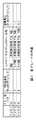
まず、このグレードレジスタ部9に格納されるグレード値について図3を用いて説明する。本実施の形態の場合このグレード値としては、「00」、「01」及び「10」の3種類がある。 First, the grade value stored in the
この場合、グレード値「00」はグレード1に相当する。またグレード値「01」はグレード2に相当し、例えばグレード1の際にインタリーブするフラッシュメモリチップCPの個数を「4個」とすると、このグレード2の際にインタリーブするフラッシュメモリチップCPの個数は「8個」となるように設定されている。さらにグレード値「10」はグレード3に相当し、このグレード3の際にインタリーブするフラッシュメモリチップCPの個数は「16個」となるように設定されている。 In this case, the grade value “00” corresponds to
これにより、グレード1の場合のデータ転送速度を「1」とすると、グレード2及びグレード3の場合のデータ転送速度は「2」及び「4」となる。またグレード1の場合の消費電力を「1」とすると、グレード2及びグレード3の場合の消費電力は「1.5」及び「3」となる。 As a result, when the data transfer rate for
次に、インタリーブについて詳細に説明する。インタリーブでは、複数のフラッシュメモリチップCPを同時に活性化し、当該活性化した複数のフラッシュメモリチップCPに対して並列的にデータ書込処理及びデータ読出処理を実行するようになされている。 Next, interleaving will be described in detail. In interleaving, a plurality of flash memory chips CP are simultaneously activated, and data write processing and data read processing are executed in parallel with respect to the activated plurality of flash memory chips CP.
ここで、第1のフラッシュメモリチップCPA0のみを活性化させてデータ書込処理を実行する場合と、第1及び第2のフラッシュメモリチップCPA0、A1を同時に活性化させてデータ書込処理を並列的に実行する場合とを比較する。Here, when the data writing process is executed by activating only the first flash memory chip CPA0 , the data writing process is performed by simultaneously activating the first and second flash memory chips CPA0 and A1. Is compared with the case of executing in parallel.
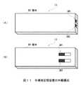
コントローラ3が第1のフラッシュメモリチップCPA0のみを活性化させてデータ書込処理を実行する場合、図4(A)に示すように、コントローラ3から所定量の書込データを第1のフラッシュメモリチップCPA0に対して転送した後、この第1のフラッシュメモリチップCPA0のキャッシュにより隠蔽される時間(T1−T2)を除くビジー時間(T2−T3)に、さらなる書込データを転送することができない。因みにこの場合におけるビジー時間とは、書込データをフラッシュメモリチップCPの記憶領域に記憶させる処理等に費やされる時間に相当する。When the
これに対してコントローラ3が第1及び第2のフラッシュメモリチップCPA0、A1を活性化させてデータ書込処理を並列的に実行する場合には、図4(B)に示すように、これら第1及び第2のフラッシュメモリチップCPA0、A1に対して書込データを順次転送することができるので、図4(A)に示したようにビジー時間に起因して書込データが転送できなくなるようなことが生じてしまうのを回避することができ、これによりデータ転送速度(データ書込処理速度)を向上させることができる。On the other hand, when the
かくして本実施の形態における半導体記憶装置1では、図5に示すように、グレードごとに活性化させるフラッシュメモリチップCPの数を変化させることにより、グレードごとにデータ転送速度(データ書込処理速度/データ読出処理速度)を変更することができる。 Thus, in the
次に、半導体記憶装置1を製造する工場等において(またはユーザがフォーマッタを起動して半導体記憶装置1をフォーマットする際において)データ転送速度を設定する際のデータ転送速度設定処理手順RT1を、図6に示すシーケンスチャートを用いて説明する。 Next, a data transfer rate setting processing procedure RT1 for setting a data transfer rate in a factory or the like that manufactures the semiconductor storage device 1 (or when the user activates the formatter and formats the semiconductor storage device 1) is shown in FIG. This will be described with reference to the sequence chart shown in FIG.
例えば、PCIエキスプレス方式に基づいて半導体記憶装置1とデータ通信可能に構成された設定装置11に対して半導体記憶装置1が接続されると、この設定装置11はステップSP1に進み、コントローラ3とフラッシュメモリ部2との間のデータ転送速度を設定するためのフォーマッタ(プログラム)を起動する。 For example, when the
次いで設定装置11はステップSP2に進み、ステップSP1において起動されたフォーマッタに従って、半導体記憶装置1のフラッシュメモリ部2に何個のフラッシュメモリチップCPが設けられているかを通知するように要求する個数通知要求信号を半導体記憶装置1に対して送信する。 Next, the setting device 11 proceeds to step SP2, and according to the formatter activated in step SP1, the number notification for requesting to notify how many flash memory chips CP are provided in the
半導体記憶装置1のコントローラ3はこの個数通知要求信号を受信するとステップSP3に進み、フラッシュメモリ部2にアクセスすることによりこのフラッシュメモリ部2に設けられているフラッシュメモリチップCPの個数を認識し、当該認識したフラッシュメモリチップCPの個数を示した個数通知信号を設定装置11に対して送信する。 Upon receiving this number notification request signal, the
設定装置11はこの個数通知信号を受信するとステップSP4に進み、この個数通知信号に示されたフラッシュメモリチップCPの個数に応じて、設定可能なグレードを表示部に表示する。 When receiving the number notification signal, the setting device 11 proceeds to step SP4, and displays a settable grade on the display unit according to the number of flash memory chips CP indicated in the number notification signal.
つまりこの設定装置11は、半導体記憶装置1からの個数通知信号に示されたフラッシュメモリチップCPの個数が例えば4個である場合、このことは図3に示したようにグレード1のみが設定可能であるので、設定可能なグレードとしてグレード1のみを表示部に表示し、半導体記憶装置1からの個数通知信号に示されたフラッシュメモリチップCPの個数が例えば8個である場合、このことは図3に示したようにグレード1及びグレード2が設定可能であるので、設定可能なグレードとしてグレード1及びグレード2を表示部に表示し、半導体記憶装置1からの個数通知信号に示されたフラッシュメモリチップCPの個数が例えば16個である場合、このことは図3に示したようにグレード1、グレード2及びグレード3が設定可能であるので、設定可能なグレードとしてグレード1、グレード2及びグレード3を表示部に表示する。 In other words, when the number of flash memory chips CP indicated by the number notification signal from the
続くステップSP5において設定装置11は、表示部に表示されているグレードの中からオペレータ等の操作によりあるグレードが指定されると、当該指定されたグレードを示したグレード指定信号を半導体記憶装置1に対して送信する。 In subsequent step SP5, when a certain grade is designated by an operation of an operator or the like from the grades displayed on the display unit, the setting device 11 sends a grade designation signal indicating the designated grade to the
半導体記憶装置1のコントローラ3はこのグレード指定信号を受信するとステップSP6に進み、メインメモリ部4に格納されているファームウェアのうち、このグレード指定信号により指定されたグレードに応じたファームウェアを有効にする。これによりこのコントローラ3は次のステップSP7において、当該指定されたグレードとなるように論理ブロックの割り当てを行う論理ブロック割当処理を実行する。 When the
つまりこの論理ブロック割当処理においては、設定装置11からのグレード指定信号によりグレード1が指定されている場合、図7に一例として示すように、4個のフラッシュメモリチップCPのそれぞれの物理ブロックを1つの論理ブロックとして割り当てる。これによりこの半導体記憶装置1のコントローラ3は、この後にパーソナルコンピュータやデジタルカメラ等の情報処理装置に接続されると、4個のフラッシュメモリチップCPに対してデータ書込処理及びデータ読出処理を並列的に実行する。 In other words, in this logical block allocation process, when
またこの論理ブロック割当処理においては、設定装置11からのグレード指定信号によりグレード2が指定されている場合、図8に一例として示すように、8個のフラッシュメモリチップCPのそれぞれの物理ブロックを1つの論理ブロックとして割り当てる。これによりこの半導体記憶装置1のコントローラ3は、この後にパーソナルコンピュータやデジタルカメラ等の情報処理装置に接続されると、8個のフラッシュメモリチップCPに対してデータ書込処理及びデータ読出処理を並列的に実行する。 Further, in this logical block allocation process, when
またこの論理ブロック割当処理においては、設定装置11からのグレード指定信号によりグレード3が指定されている場合、図9に一例として示すように、16個のフラッシュメモリチップCPのそれぞれの物理ブロックを1つの論理ブロックとして割り当てる。これによりこの半導体記憶装置1のコントローラ3は、この後にパーソナルコンピュータやデジタルカメラ等の情報処理装置に接続されると、16個のフラッシュメモリチップCPに対してデータ書込処理及びデータ読出処理を並列的に実行するようになされている。 In this logical block allocation process, when
そして半導体記憶装置1のコントローラ3は続くステップSP8に移り、この論理ブロック割当処理により論理ブロックの割り当てが成功したグレードのグレード値を、グレードレジスタ部9に記憶させる。次いで半導体記憶装置1のコントローラ3はステップSP9に移り、論理ブロック割当処理により論理ブロックの割り当てが成功したグレードのグレード値を示したグレード値通知信号を、設定装置11に対して送信する。 Then, the
設定装置11はこのグレード値通知信号を受信するとステップSP10に移り、このグレード値通知信号に示されたグレード値に対応するグレードを表示部に表示することにより、当該グレードが半導体記憶装置1に対して設定されたことをオペレータに通知するようになされている。 When the setting device 11 receives the grade value notification signal, the setting device 11 proceeds to step SP10, and displays the grade corresponding to the grade value indicated in the grade value notification signal on the display unit, so that the grade is transmitted to the
以上の構成においてこの半導体記憶装置1のコントローラ3は、設定装置11からグレードを指定するためのグレード指定信号を受信すると、当該受信したグレード指定信号により指定されたグレードに対応する個数のフラッシュメモリチップCPに対してデータ書込処理及びデータ読出処理を並列的に実行し得るように論理ブロック割当処理を実行するようにした。 In the above configuration, when the
かくするにつきこの半導体記憶装置1は、設定装置11を介して指定されたグレードに応じて、データ書込処理速度及びデータ読出処理速度を変更することができる。 In this way, the
(2)第2の実施の形態
図1との対応部分に同一符号を付して示す図10において、1Xは全体として第2の実施の形態における半導体記憶装置を示し、第1のディップスイッチSW1及び第2のディップスイッチSW2を有する点を除いて、第1の実施の形態における半導体記憶装置1とほぼ同様の構成でなる。(2) Second Embodiment In FIG. 10, in which parts corresponding to those in FIG. 1 are assigned the same reference numerals, 1X indicates the semiconductor memory device in the second embodiment as a whole, and the first dip switch SW1 Except for the point that the second dip switch SW2 is provided, the
つまりこの第2の実施の形態における半導体記憶装置1Xは、例えば図11(A)に示すように、所定の厚みを有するようにして略長方形状に形成された筐体BDの側面に対して、第1のディップスイッチSW1及び第2のディップスイッチSW2が設けられている。因みにこの第1のディップスイッチSW1及び第2のディップスイッチSW2は、例えば図11(B)に示すように、筐体BDの表面等に設けるようにしても良い。 In other words, the
この第1のディップスイッチSW1及び第2のディップスイッチSW2は、例えば図12に示すように、略長方形状に形成されたスライド溝21A、21Bの一端又は他端方向にスイッチ部22A、22Bがスライドするように構成されている。 As shown in FIG. 12, for example, the first dip switch SW1 and the second dip switch SW2 are configured such that the
本実施の形態の場合、例えば図12(A)に示すように、第1のディップスイッチSW1におけるスイッチ部22Aがスライド溝21Aの一端側にスライドされ、かつ、第2のディップスイッチSW2におけるスイッチ部22Bがスライド溝21Bの一端側にスライドされると、第1のディップスイッチSW1及び第2のディップスイッチSW2からグレード1を示すグレード値「00」がこの半導体記憶装置1Xのコントローラ3に供給されるようになされている。 In the case of the present embodiment, for example, as shown in FIG. 12A, the
また本実施の形態の場合、例えば図12(B)に示すように、第1のディップスイッチSW1におけるスイッチ部22Aがスライド溝21Aの一端側にスライドされ、かつ、第2のディップスイッチSW2におけるスイッチ部22Bがスライド溝21Bの他端側にスライドされると、第1のディップスイッチSW1及び第2のディップスイッチSW2からグレード2を示すグレード値「01」がこの半導体記憶装置1Xのコントローラ3に供給されるようになされている。 In the case of the present embodiment, for example, as shown in FIG. 12B, the
また本実施の形態の場合、例えば図12(C)に示すように、第1のディップスイッチSW1におけるスイッチ部22Aがスライド溝21Aの他端側にスライドされ、かつ、第2のディップスイッチSW2におけるスイッチ部22Bがスライド溝21Bの一端側にスライドされると、第1のディップスイッチSW1及び第2のディップスイッチSW2からグレード3を示すグレード値「10」がこの半導体記憶装置1Xのコントローラ3に供給されるようになされている。 In the case of the present embodiment, for example, as shown in FIG. 12C, the
次に、この第1のディップスイッチSW1及び第2のディップスイッチSW2を介してデータ転送速度を設定する際のデータ転送速度設定処理手順RT2を、図13に示すフローチャートを用いて説明する。 Next, the data transfer rate setting processing procedure RT2 for setting the data transfer rate via the first dip switch SW1 and the second dip switch SW2 will be described with reference to the flowchart shown in FIG.
ステップSP11においては、半導体記憶装置1Xの筐体BDに設けられた第1のディップスイッチSW1及び第2のディップスイッチSW2がユーザによって操作されることにより、グレード1、グレード2及びグレード3のうちの何れかのグレードが指定されると、これに応じてこの第1のディップスイッチSW1及び第2のディップスイッチSW2は、当該指定されたグレードを示すグレード値をコントローラ3に対して入力する。 In step SP11, the first dip switch SW1 and the second dip switch SW2 provided on the housing BD of the
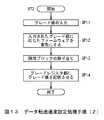
これに応じてこのコントローラ3はステップSP12に進み、メインメモリ部4に格納されているファームウェアのうち、当該入力されたグレード値に応じたファームウェアを有効にする。これによりこのコントローラ3は次のステップSP13において、当該入力されたグレード値に対応するグレードとなるように論理ブロックの割り当てを行う論理ブロック割当処理を実行する。 In response to this, the
つまりこの論理ブロック割当処理においては、当該入力されたグレード値がグレード1を示す「00」である場合、図7に一例として示したように、4個のフラッシュメモリチップCPのそれぞれの物理ブロックを1つの論理ブロックとして割り当てる。またこの論理ブロック割当処理においては、当該入力されたグレード値がグレード2を示す「01」である場合、図8に一例として示したように、8個のフラッシュメモリチップCPのそれぞれの物理ブロックを1つの論理ブロックとして割り当てる。またこの論理ブロック割当処理においては、当該入力されたグレード値がグレード3を示す「10」である場合、図9に一例として示したように、16個のフラッシュメモリチップCPのそれぞれの物理ブロックを1つの論理ブロックとして割り当てる。 That is, in this logical block allocation process, when the input grade value is “00” indicating
そして半導体記憶装置1Xのコントローラ3は続くステップSP14に移り、この論理ブロック割当処理により論理ブロックの割り当てが成功したグレードのグレード値を、グレードレジスタ部9に記憶させるようになされている。 Then, the
以上の構成においてこの半導体記憶装置1Xのコントローラ3は、第1のディップスイッチSW1及び第2のディップスイッチSW2からグレードを指定するグレード値を受信すると、当該受信したグレード値に対応する個数のフラッシュメモリチップCPに対してデータ書込処理及びデータ読出処理を並列的に実行し得るように論理ブロック割当処理を実行するようにした。 In the above configuration, when the
かくするにつきこの半導体記憶装置1Xは、第1のディップスイッチSW1及び第2のディップスイッチSW2を介して指定されたグレードに応じて、データ書込処理速度やデータ読出処理速度を変更することができる。 Thus, the
(3)第3の実施の形態
この第3の実施の形態においては、図1に示した第1の実施の形態における半導体記憶装置1と同様の構成でなる。従ってここでは図14に示すシーケンスチャートを用いて、コントローラ3とフラッシュメモリ部2との間のデータ転送速度を設定する際のデータ転送速度設定処理手順RT3を中心に説明する。(3) Third Embodiment This third embodiment has the same configuration as that of the
この半導体記憶装置1のコントローラ3は、パーソナルコンピュータやデジタルカメラ等に相当する情報処理装置31に対して接続されることによりこの情報処理装置31から電力が供給開始されるとステップSP21に移り、フラッシュメモリ部2にアクセスすることによりこのフラッシュメモリ部2に設けられているフラッシュメモリチップCPの個数を認識する。 When the
因みに本実施の形態の場合この半導体記憶装置1のコントローラ3は、接続先の情報処理装置31から電力が供給開始された際、初期設定としてコントローラ3とフラッシュメモリ部2とのデータ転送速度をグレード1に設定するようになされている。 Incidentally, in the case of the present embodiment, the
次いでこの半導体記憶装置1のコントローラ3はステップSP22に移り、ステップSP21において認識したフラッシュメモリチップCPの個数に基づいて設定可能なグレードを認識する。つまりこのコントローラ3は、ステップSP21において認識したフラッシュメモリチップCPの個数が例えば4個である場合には設定可能なグレードとしてグレード1のみを認識し、ステップSP21において認識したフラッシュメモリチップCPの個数が例えば8個である場合には設定可能なグレードとしてグレード1及びグレード2を認識し、ステップSP21において認識したフラッシュメモリチップCPの個数が例えば16個である場合には設定可能なグレードとしてグレード1、グレード2及びグレード3を認識する。そしてこのコントローラ3は、当該認識した設定可能なグレードを示してなる設定可能グレード情報と、現在設定されているグレード(つまりグレード1)のグレード値「00」を示してなる現グレード情報とを、グレードレジスタ部9に記憶する。 Next, the
一方情報処理装置31はステップSP23において、接続されている半導体記憶装置1から所定の属性情報を読み出し、当該読み出した属性情報に基づいて半導体記憶装置1が接続されていることを認識する。 On the other hand, in step SP23, the
また半導体記憶装置1のコントローラ3はステップSP24に移り、グレードレジスタ部9に記憶した設定可能グレード情報及び現グレード情報を、情報処理装置31に対して送信する。 Further, the
情報処理装置31は半導体記憶装置1から設定可能グレード情報及び現グレード情報を受信するとステップSP25に移り、この現グレード情報に示されているグレード1が、情報処理装置31において現在実行している処理(アプリケーション)に適合しているか否かを判定する。例えばこの情報処理装置31は、現在実行している処理がデータ量の大きいデータを半導体記憶装置1に記憶させる処理であれば、かかる現グレード情報に示されているグレード1を不適合と判定する。そしてこのように不適合と判定した場合この情報処理装置31は、半導体記憶装置1から受信した設定可能グレード情報に示されている設定可能なグレードの中から、現在実行している処理に適合する例えばグレード3を選択し、当該選択したグレード3を指定するグレード指定信号を半導体記憶装置1に対して送信する。 When the
半導体記憶装置1のコントローラ3はこのグレード指定信号を受信するとステップSP26に進み、メインメモリ部4に格納されているファームウェアのうち、このグレード指定信号により指定されたグレード3に応じたファームウェアを有効にする。これによりこのコントローラ3は次のステップSP27において、グレード3となるように論理ブロックの割り当てを行う論理ブロック割当処理を実行する。 When the
つまりこの論理ブロック割当処理においては、図9に一例として示したように、16個のフラッシュメモリチップCPのそれぞれの物理ブロックを1つの論理ブロックとして割り当てる。 That is, in this logical block allocation process, as shown as an example in FIG. 9, each physical block of the 16 flash memory chips CP is allocated as one logical block.
そして半導体記憶装置1のコントローラ3は続くステップSP28に移り、この論理ブロック割当処理により論理ブロックの割り当てが成功したグレード3のグレード値「10」を、現グレード情報としてグレードレジスタ部9に記憶させる。次いで半導体記憶装置1のコントローラ3はステップSP29に移り、グレード3の設定が完了した旨を通知するための設定完了通知信号を情報処理装置31に対して送信する。 Then, the
情報処理装置31はこの設定完了通知信号を受信するとステップSP30に移り、この設定完了通知信号により通知されたグレード3により半導体記憶装置1とのデータ通信を実行する。 When the
以上の構成においてこの半導体記憶装置1が接続されている情報処理装置31は、現在実行している処理(アプリケーション)の種類に応じたグレードを指定するグレード指定信号を半導体記憶装置1に対して送信する。 In the above configuration, the
この半導体記憶装置1のコントローラ3は、情報処理装置31からグレード指定信号を受信すると、当該受信したグレード指定信号により指定されたグレードに対応する個数のフラッシュメモリチップCPに対してデータ書込処理及びデータ読出処理を並列的に実行し得るように論理ブロック割当処理を実行するようにした。 When the
かくするにつきこの半導体記憶装置1は、接続先の情報処理装置31において実行されている処理に応じて、データ書込処理速度やデータ読出処理速度を変更することができる。 In this way, the
また本実施の形態の場合この半導体記憶装置1は、接続先の情報処理装置31において実行されている処理に応じて、データ書込処理速度やデータ読出処理速度を変更するようにしたが、本発明はこれに限らず、接続先の情報処理装置31における電力供給状況に応じて、データ書込処理速度やデータ読出処理速度を変更するようにしても良い。つまりこの場合半導体記憶装置1は、例えば、接続先の情報処理装置31がその内部に設けられたバッテリからの電力供給により動作している場合であれば、データ書込処理速度やデータ読出処理速度を低下させることにより、かかるバッテリの充電量を急激に減少させてしまうことを回避することができる。また半導体記憶装置1は、例えば、接続先の情報処理装置31が商用電源からの電源供給により動作している場合であれば、データ書込処理速度やデータ読出処理速度を上げることにより、データ書込処理やデータ読出処理の処理時間を短縮させることができる。 In the case of the present embodiment, the
(4)他の実施の形態
なお上述した第1乃至第3の実施の形態においては、半導体記憶装置1に設けるフラッシュメモリチップCPの個数を、16個にする場合について述べたが、本発明はこれに限らず、複数個であれば16個以下又は16個以上であっても良い。(4) Other Embodiments In the first to third embodiments described above, the case where the number of flash memory chips CP provided in the
因みに上述した第1乃至第3の実施の形態においては、グレード1、グレード2及びグレード3の3種類を実現するため、半導体記憶装置1に対して16個のフラッシュメモリチップCPを設ける場合について述べた。しかしながら、グレード1だけを実現するために4個のフラッシュメモリチップCPのみが半導体記憶装置1に設けられる場合には、当該半導体記憶装置1に対して上述した第1及び第2のディップスイッチSW1、SW2を設けないようにしても良い。若しくは当該半導体記憶装置1のコントローラ3内部に、設定可能なグレード(つまりグレード1)を示したデータを記憶するレジスタを設け、当該半導体記憶装置1のコントローラ3がこのレジスタに記憶されているデータに基づいて、設定可能なグレード以外のグレード(グレード2及びグレード3)を設定無効化するようにしても良い。 Incidentally, in the first to third embodiments described above, a case where 16 flash memory chips CP are provided in the
また、グレード1及びグレード2だけを実現するために8個のフラッシュメモリチップCPのみが半導体記憶装置1に設けられる場合には、グレード1及びグレード2の切り替えだけを行い得るように、当該半導体記憶装置1に対してディップスイッチSWを1つだけ設けるようにしても良い。若しくは当該半導体記憶装置1のコントローラ3内部に、設定可能なグレード(つまりグレード1及びグレード2)を示したデータを記憶するレジスタを設け、当該半導体記憶装置1のコントローラ3がこのレジスタに記憶されているデータに基づいて、設定可能なグレード以外のグレード(グレード3)を設定無効化するようにしても良い。 Further, when only eight flash memory chips CP are provided in the
また上述した第1乃至第3の実施の形態においては、データを記憶する複数のメモリ手段として、フラッシュメモリチップCPを適用する場合について述べたが、本発明はこれに限らず、この他種々の半導体メモリやその他メモリを適用することができる。 In the first to third embodiments described above, the case where the flash memory chip CP is applied as the plurality of memory means for storing data has been described. However, the present invention is not limited to this, and various other types are also available. A semiconductor memory or other memory can be applied.
さらに上述した第1乃至第3の実施の形態においては、メモリ手段を制御する制御手段として、図1等に示したコントローラ3を適用する場合について述べたが、本発明はこれに限らず、この他種々の構成を適用することができる。 Further, in the first to third embodiments described above, the case where the
さらに上述した第1乃至第3の実施の形態においては、データ書込処理速度及びデータ読出処理速度が最も遅いグレード1であるときでも、最低4個のフラッシュメモリチップCPを活性化させることにより、データ書込処理速度及びデータ読出処理速度を保障する場合について述べたが、本発明はこれに限らず、この他種々の手法を適用することができる。 Further, in the first to third embodiments described above, even when the data writing processing speed and the data reading processing speed are the
本発明は、例えば、パーソナルコンピュータやデジタルカメラ等の情報処理装置から供給されるデータを内部の半導体メモリに対して記憶するようになされた半導体記憶装置に利用することができる。 The present invention can be used, for example, in a semiconductor memory device configured to store data supplied from an information processing device such as a personal computer or a digital camera in an internal semiconductor memory.
1、1X……半導体記憶装置、2……フラッシュメモリ部、3……コントローラ、9……グレードレジスタ部、CP……フラッシュメモリチップ、SW……ディップスイッチ。
DESCRIPTION OF
Claims (5)
Translated fromJapanese上記メモリ手段を制御する制御手段と
を有し、
上記制御手段は、
供給された指定信号により指定された個数の上記メモリ手段に対して、接続している接続先装置から供給されたデータを書き込むデータ書込処理又は上記接続先装置から要求されたデータを読み出すデータ読出処理を並列的に実行する
ことを特徴とする記憶装置。A plurality of memory means for storing data;
Control means for controlling the memory means,
The control means includes
Data writing process for writing data supplied from the connected device connected to the number of memory means specified by the supplied specifying signal, or data reading for reading data requested from the connected device A storage device that performs processing in parallel.
ことを特徴とする請求項1に記載の記憶装置。The storage device according to claim 1, further comprising data communication means for performing data communication with the connection destination device based on a PCI Express system.
上記接続先装置から供給された上記指定信号により指定された個数の上記メモリ手段に対して、当該接続先装置から供給されたデータを書き込むデータ書込処理又は当該接続先装置から要求されたデータを読み出すデータ読出処理を並列的に実行する
ことを特徴とする請求項1に記載の記憶装置。The control means includes
Data write processing for writing data supplied from the connection destination device or data requested from the connection destination device to the number of memory means specified by the specification signal supplied from the connection destination device. The storage device according to claim 1, wherein the read data reading process is executed in parallel.
上記指定手段は、ユーザにより指定された上記メモリ手段の個数を示した上記指定信号を生成して上記制御手段に供給する
ことを特徴とする請求項1に記載の記憶装置。Having designation means for allowing the user to designate the number of the memory means,
The storage device according to claim 1, wherein the designation unit generates the designation signal indicating the number of the memory units designated by a user and supplies the designation signal to the control unit.
上記メモリ手段を制御する制御手段と
を有し、
接続している接続先装置から供給されたデータを書き込むデータ書込処理速度又は上記接続先装置から要求されたデータを読み出すデータ読出処理速度を保障するようにした
ことを特徴とする記憶装置。
A plurality of memory means for storing data;
Control means for controlling the memory means,
A storage device characterized by guaranteeing a data writing processing speed for writing data supplied from a connected destination device or a data reading processing speed for reading data requested from the connection destination device.
Priority Applications (4)
| Application Number | Priority Date | Filing Date | Title |
|---|---|---|---|
| JP2005004299AJP2006195569A (en) | 2005-01-11 | 2005-01-11 | Memory unit |
| KR1020060001608AKR101256664B1 (en) | 2005-01-11 | 2006-01-06 | Memory device |
| CNB2006100739038ACN100541412C (en) | 2005-01-11 | 2006-01-11 | Memory storage |
| US11/329,843US7325104B2 (en) | 2005-01-11 | 2006-01-11 | Storage device using interleaved memories to control power consumption |
Applications Claiming Priority (1)
| Application Number | Priority Date | Filing Date | Title |
|---|---|---|---|
| JP2005004299AJP2006195569A (en) | 2005-01-11 | 2005-01-11 | Memory unit |
Related Child Applications (1)
| Application Number | Title | Priority Date | Filing Date |
|---|---|---|---|
| JP2010198309ADivisionJP2010282654A (en) | 2010-09-03 | 2010-09-03 | Storage device and information processor |
Publications (2)
| Publication Number | Publication Date |
|---|---|
| JP2006195569Atrue JP2006195569A (en) | 2006-07-27 |
| JP2006195569A5 JP2006195569A5 (en) | 2010-04-22 |
Family
ID=36801630
Family Applications (1)
| Application Number | Title | Priority Date | Filing Date |
|---|---|---|---|
| JP2005004299APendingJP2006195569A (en) | 2005-01-11 | 2005-01-11 | Memory unit |
Country Status (4)
| Country | Link |
|---|---|
| US (1) | US7325104B2 (en) |
| JP (1) | JP2006195569A (en) |
| KR (1) | KR101256664B1 (en) |
| CN (1) | CN100541412C (en) |
Cited By (12)
| Publication number | Priority date | Publication date | Assignee | Title |
|---|---|---|---|---|
| JP2011513823A (en)* | 2008-02-28 | 2011-04-28 | ノキア コーポレイション | Extended usage range for memory devices |
| JP2011170505A (en)* | 2010-02-17 | 2011-09-01 | Mitsubishi Electric Corp | Semiconductor disk device |
| JP2011203905A (en)* | 2010-03-25 | 2011-10-13 | Toshiba Corp | Memory system |
| JP2012141944A (en)* | 2010-12-16 | 2012-07-26 | Toshiba Corp | Memory system |
| JP2012532398A (en)* | 2009-07-06 | 2012-12-13 | マイクロン テクノロジー, インク. | Data transfer management |
| US8364884B2 (en) | 2008-02-29 | 2013-01-29 | Kabushiki Kaisha Toshiba | Memory system with a memory controller controlling parallelism of driving memories |
| US8874824B2 (en) | 2009-06-04 | 2014-10-28 | Memory Technologies, LLC | Apparatus and method to share host system RAM with mass storage memory RAM |
| US9311226B2 (en) | 2012-04-20 | 2016-04-12 | Memory Technologies Llc | Managing operational state data of a memory module using host memory in association with state change |
| JP2018036795A (en)* | 2016-08-30 | 2018-03-08 | 東芝メモリ株式会社 | Memory system |
| US10324854B2 (en) | 2015-03-23 | 2019-06-18 | Fujitsu Limited | Information processing apparatus and control method for dynamic cache management |
| JP2019149197A (en)* | 2019-05-09 | 2019-09-05 | 東芝メモリ株式会社 | Method for controlling a memory system |
| JP2022042183A (en)* | 2020-09-02 | 2022-03-14 | 株式会社東芝 | Memory device, video server, broadcasting system, and memory access control method |
Families Citing this family (19)
| Publication number | Priority date | Publication date | Assignee | Title |
|---|---|---|---|---|
| US8086779B2 (en)* | 2006-12-04 | 2011-12-27 | Signal Storage Innovations, L.L.C. | Data recorder for multiple media formats |
| US8433845B2 (en)* | 2009-04-08 | 2013-04-30 | Google Inc. | Data storage device which serializes memory device ready/busy signals |
| US8205037B2 (en)* | 2009-04-08 | 2012-06-19 | Google Inc. | Data storage device capable of recognizing and controlling multiple types of memory chips operating at different voltages |
| US20100262979A1 (en)* | 2009-04-08 | 2010-10-14 | Google Inc. | Circular command queues for communication between a host and a data storage device |
| JP4643729B2 (en)* | 2009-07-09 | 2011-03-02 | 株式会社東芝 | Interleave control device, interleave control method, and memory system |
| JP5540969B2 (en)* | 2009-09-11 | 2014-07-02 | ソニー株式会社 | Nonvolatile memory device, memory controller, and memory system |
| CN102109966B (en)* | 2009-12-24 | 2017-01-18 | 马维尔国际贸易有限公司 | Method and system for object-oriented data storage |
| US20110173462A1 (en)* | 2010-01-11 | 2011-07-14 | Apple Inc. | Controlling and staggering operations to limit current spikes |
| US20110252263A1 (en)* | 2010-04-13 | 2011-10-13 | Byungcheol Cho | Semiconductor storage device |
| US8522055B2 (en) | 2010-07-26 | 2013-08-27 | Apple Inc. | Peak power validation methods and systems for non-volatile memory |
| US8826051B2 (en) | 2010-07-26 | 2014-09-02 | Apple Inc. | Dynamic allocation of power budget to a system having non-volatile memory and a processor |
| US8555095B2 (en)* | 2010-07-26 | 2013-10-08 | Apple Inc. | Methods and systems for dynamically controlling operations in a non-volatile memory to limit power consumption |
| US20120221767A1 (en) | 2011-02-28 | 2012-08-30 | Apple Inc. | Efficient buffering for a system having non-volatile memory |
| US8645723B2 (en) | 2011-05-11 | 2014-02-04 | Apple Inc. | Asynchronous management of access requests to control power consumption |
| KR102145420B1 (en) | 2013-07-25 | 2020-08-18 | 삼성전자주식회사 | Storage system changing data transfer speed manager and method for changing data transfer speed thereof |
| CN104268049B (en)* | 2014-09-30 | 2017-01-25 | 北京金山安全软件有限公司 | Method, device and terminal for judging storage device abnormity |
| JP6212073B2 (en)* | 2015-06-29 | 2017-10-11 | ファナック株式会社 | Numerical control device with a function to automatically select the storage location according to the contents of the program |
| KR102678655B1 (en)* | 2019-07-05 | 2024-06-27 | 에스케이하이닉스 주식회사 | Memory interface, data storage device including the same and operating method thereof |
| CN113342155A (en)* | 2020-02-18 | 2021-09-03 | 浙江宇视科技有限公司 | Data storage method, device, equipment and storage medium |
Citations (7)
| Publication number | Priority date | Publication date | Assignee | Title |
|---|---|---|---|---|
| JPH0883149A (en)* | 1994-09-14 | 1996-03-26 | Hitachi Ltd | Power environment adaptive information storage device, host device thereof and control method thereof |
| JPH1069420A (en)* | 1996-08-29 | 1998-03-10 | Sony Corp | Information recording and reproducing device and information recording and reproducing method |
| JP2000132283A (en)* | 1998-10-21 | 2000-05-12 | Nec Corp | Method for reducing power consumption of semiconductor memory |
| JP2001297316A (en)* | 2000-04-14 | 2001-10-26 | Mitsubishi Electric Corp | Memory card and control method thereof |
| JP2003036205A (en)* | 2001-07-24 | 2003-02-07 | Matsushita Electric Ind Co Ltd | Storage device |
| WO2003029951A2 (en)* | 2001-09-28 | 2003-04-10 | Lexar Media, Inc. | Non-volatile memory control |
| WO2003081407A1 (en)* | 2002-03-27 | 2003-10-02 | Nokia Corporation | A method and a system for determining the power consumption in connection with an electronic device, and an electronic device |
Family Cites Families (9)
| Publication number | Priority date | Publication date | Assignee | Title |
|---|---|---|---|---|
| US5226134A (en)* | 1990-10-01 | 1993-07-06 | International Business Machines Corp. | Data processing system including a memory controller for direct or interleave memory accessing |
| JP3060347B2 (en)* | 1992-12-28 | 2000-07-10 | キヤノン株式会社 | Recording device |
| JP3821536B2 (en)* | 1997-05-16 | 2006-09-13 | 沖電気工業株式会社 | Nonvolatile semiconductor disk device |
| US6418535B1 (en)* | 1999-04-28 | 2002-07-09 | International Business Machines Corporation | Bi-level power saver method for portable or laptop computer |
| US6823516B1 (en)* | 1999-08-10 | 2004-11-23 | Intel Corporation | System and method for dynamically adjusting to CPU performance changes |
| CN1229708C (en)* | 2000-11-28 | 2005-11-30 | Lg电子株式会社 | A Method of Controlling Disk Write Operation Based on Battery Remaining Capacity |
| CN2545677Y (en)* | 2002-04-26 | 2003-04-16 | 群联电子股份有限公司 | Universal serial bus flash memory integrated circuit with memory card access interface |
| US7644406B2 (en)* | 2003-01-21 | 2010-01-05 | Hewlett-Packard Development Company, L.P. | Update system capable of updating software across multiple FLASH chips |
| US7152136B1 (en)* | 2004-08-03 | 2006-12-19 | Altera Corporation | Implementation of PCI express |
- 2005
- 2005-01-11JPJP2005004299Apatent/JP2006195569A/enactivePending
- 2006
- 2006-01-06KRKR1020060001608Apatent/KR101256664B1/ennot_activeExpired - Fee Related
- 2006-01-11CNCNB2006100739038Apatent/CN100541412C/ennot_activeExpired - Fee Related
- 2006-01-11USUS11/329,843patent/US7325104B2/ennot_activeExpired - Fee Related
Patent Citations (7)
| Publication number | Priority date | Publication date | Assignee | Title |
|---|---|---|---|---|
| JPH0883149A (en)* | 1994-09-14 | 1996-03-26 | Hitachi Ltd | Power environment adaptive information storage device, host device thereof and control method thereof |
| JPH1069420A (en)* | 1996-08-29 | 1998-03-10 | Sony Corp | Information recording and reproducing device and information recording and reproducing method |
| JP2000132283A (en)* | 1998-10-21 | 2000-05-12 | Nec Corp | Method for reducing power consumption of semiconductor memory |
| JP2001297316A (en)* | 2000-04-14 | 2001-10-26 | Mitsubishi Electric Corp | Memory card and control method thereof |
| JP2003036205A (en)* | 2001-07-24 | 2003-02-07 | Matsushita Electric Ind Co Ltd | Storage device |
| WO2003029951A2 (en)* | 2001-09-28 | 2003-04-10 | Lexar Media, Inc. | Non-volatile memory control |
| WO2003081407A1 (en)* | 2002-03-27 | 2003-10-02 | Nokia Corporation | A method and a system for determining the power consumption in connection with an electronic device, and an electronic device |
Cited By (34)
| Publication number | Priority date | Publication date | Assignee | Title |
|---|---|---|---|---|
| US12417022B2 (en) | 2008-02-28 | 2025-09-16 | Memory Technologies Llc | Extended utilization area for a memory device |
| US10540094B2 (en) | 2008-02-28 | 2020-01-21 | Memory Technologies Llc | Extended utilization area for a memory device |
| US11550476B2 (en) | 2008-02-28 | 2023-01-10 | Memory Technologies Llc | Extended utilization area for a memory device |
| US11182079B2 (en) | 2008-02-28 | 2021-11-23 | Memory Technologies Llc | Extended utilization area for a memory device |
| US9367486B2 (en) | 2008-02-28 | 2016-06-14 | Memory Technologies Llc | Extended utilization area for a memory device |
| US11829601B2 (en) | 2008-02-28 | 2023-11-28 | Memory Technologies Llc | Extended utilization area for a memory device |
| JP2013211033A (en)* | 2008-02-28 | 2013-10-10 | Nokia Corp | Expanded utilization range for memory device |
| US8601228B2 (en) | 2008-02-28 | 2013-12-03 | Memory Technologies, LLC | Extended utilization area for a memory device |
| US11907538B2 (en) | 2008-02-28 | 2024-02-20 | Memory Technologies Llc | Extended utilization area for a memory device |
| JP2011513823A (en)* | 2008-02-28 | 2011-04-28 | ノキア コーポレイション | Extended usage range for memory devices |
| US11494080B2 (en) | 2008-02-28 | 2022-11-08 | Memory Technologies Llc | Extended utilization area for a memory device |
| US9063850B2 (en) | 2008-02-28 | 2015-06-23 | Memory Technologies Llc | Extended utilization area for a memory device |
| US8364884B2 (en) | 2008-02-29 | 2013-01-29 | Kabushiki Kaisha Toshiba | Memory system with a memory controller controlling parallelism of driving memories |
| US11733869B2 (en) | 2009-06-04 | 2023-08-22 | Memory Technologies Llc | Apparatus and method to share host system RAM with mass storage memory RAM |
| US9983800B2 (en) | 2009-06-04 | 2018-05-29 | Memory Technologies Llc | Apparatus and method to share host system RAM with mass storage memory RAM |
| US8874824B2 (en) | 2009-06-04 | 2014-10-28 | Memory Technologies, LLC | Apparatus and method to share host system RAM with mass storage memory RAM |
| US12360670B2 (en) | 2009-06-04 | 2025-07-15 | Memory Technologies Llc | Apparatus and method to share host system RAM with mass storage memory RAM |
| US11775173B2 (en) | 2009-06-04 | 2023-10-03 | Memory Technologies Llc | Apparatus and method to share host system RAM with mass storage memory RAM |
| US10983697B2 (en) | 2009-06-04 | 2021-04-20 | Memory Technologies Llc | Apparatus and method to share host system RAM with mass storage memory RAM |
| US9047273B2 (en) | 2009-07-06 | 2015-06-02 | Micron Technology, Inc. | Data transfer management |
| JP2012532398A (en)* | 2009-07-06 | 2012-12-13 | マイクロン テクノロジー, インク. | Data transfer management |
| JP2011170505A (en)* | 2010-02-17 | 2011-09-01 | Mitsubishi Electric Corp | Semiconductor disk device |
| US8671260B2 (en) | 2010-03-25 | 2014-03-11 | Kabushiki Kaisha Toshiba | Memory system |
| JP2011203905A (en)* | 2010-03-25 | 2011-10-13 | Toshiba Corp | Memory system |
| JP2012141944A (en)* | 2010-12-16 | 2012-07-26 | Toshiba Corp | Memory system |
| US10042586B2 (en) | 2012-04-20 | 2018-08-07 | Memory Technologies Llc | Managing operational state data in memory module |
| US11226771B2 (en) | 2012-04-20 | 2022-01-18 | Memory Technologies Llc | Managing operational state data in memory module |
| US11782647B2 (en) | 2012-04-20 | 2023-10-10 | Memory Technologies Llc | Managing operational state data in memory module |
| US9311226B2 (en) | 2012-04-20 | 2016-04-12 | Memory Technologies Llc | Managing operational state data of a memory module using host memory in association with state change |
| US10324854B2 (en) | 2015-03-23 | 2019-06-18 | Fujitsu Limited | Information processing apparatus and control method for dynamic cache management |
| US10754560B2 (en) | 2016-08-30 | 2020-08-25 | Toshiba Memory Corporation | Predicting and controlling power consumption for a storage device |
| JP2018036795A (en)* | 2016-08-30 | 2018-03-08 | 東芝メモリ株式会社 | Memory system |
| JP2019149197A (en)* | 2019-05-09 | 2019-09-05 | 東芝メモリ株式会社 | Method for controlling a memory system |
| JP2022042183A (en)* | 2020-09-02 | 2022-03-14 | 株式会社東芝 | Memory device, video server, broadcasting system, and memory access control method |
Also Published As
| Publication number | Publication date |
|---|---|
| CN1825271A (en) | 2006-08-30 |
| KR20060082040A (en) | 2006-07-14 |
| US20060184758A1 (en) | 2006-08-17 |
| US7325104B2 (en) | 2008-01-29 |
| KR101256664B1 (en) | 2013-04-19 |
| CN100541412C (en) | 2009-09-16 |
Similar Documents
| Publication | Publication Date | Title |
|---|---|---|
| JP2006195569A (en) | Memory unit | |
| JP5073667B2 (en) | Portable data storage device using SLC and MLC flash memory | |
| JP5420648B2 (en) | Semiconductor device | |
| US8310880B2 (en) | Virtual channel support in a nonvolatile memory controller | |
| US8429374B2 (en) | System and method for read-while-write with NAND memory device | |
| JP5400875B2 (en) | MEMORY CONTROLLER, NONVOLATILE STORAGE DEVICE, ACCESS DEVICE, NONVOLATILE STORAGE SYSTEM, DATA WRITE METHOD, AND PROGRAM | |
| JP5090819B2 (en) | Memory card and data storage method | |
| KR101812300B1 (en) | Allocation of memory buffers in computing system with multiple memory channels | |
| US20110258372A1 (en) | Memory device, host device, and memory system | |
| WO2017020647A1 (en) | Novel storage-based embedded file system and realization method thereof | |
| JP2004086503A (en) | Memory card recognition system, memory card / host device, memory card, storage area switching method, and storage area switching program | |
| CN108536623A (en) | Multichannel NAND Flash controllers and movable storage device | |
| CN213338708U (en) | Control unit and storage device | |
| CN104077080B (en) | Memory access method, memory access control method, SPI flash memory device and controller thereof | |
| KR100746364B1 (en) | Memory sharing method and device | |
| US7836263B2 (en) | Nonvolatile memory controlling method and nonvolatile memory controlling apparatus | |
| JP2010282654A (en) | Storage device and information processor | |
| JP2006011926A (en) | Serial data transfer system, serial data transfer apparatus, serial data transfer method, and image forming apparatus | |
| JP2009176359A (en) | Nonvolatile semiconductor memory device | |
| US8166228B2 (en) | Non-volatile memory system and method for reading and storing sub-data during partially overlapping periods | |
| KR100547789B1 (en) | Portable terminal and method for exchanging data with external device using internal storage media | |
| JP2007310927A (en) | Nonvolatile memory, memory controller, nonvolatile storage device, and nonvolatile storage system | |
| KR100592108B1 (en) | Digital processing device having a rapid data transfer method and a shared memory between a plurality of processors | |
| JPWO2008102610A1 (en) | MEMORY CONTROLLER, NONVOLATILE STORAGE DEVICE, AND NONVOLATILE STORAGE SYSTEM | |
| KR20110000878A (en) | Memory device equipped with NAND flash memory and its read operation method |
Legal Events
| Date | Code | Title | Description |
|---|---|---|---|
| A621 | Written request for application examination | Free format text:JAPANESE INTERMEDIATE CODE: A621 Effective date:20070809 | |
| A521 | Request for written amendment filed | Free format text:JAPANESE INTERMEDIATE CODE: A523 Effective date:20100305 | |
| A871 | Explanation of circumstances concerning accelerated examination | Free format text:JAPANESE INTERMEDIATE CODE: A871 Effective date:20100305 | |
| A975 | Report on accelerated examination | Free format text:JAPANESE INTERMEDIATE CODE: A971005 Effective date:20100311 | |
| A131 | Notification of reasons for refusal | Free format text:JAPANESE INTERMEDIATE CODE: A131 Effective date:20100318 | |
| A521 | Request for written amendment filed | Free format text:JAPANESE INTERMEDIATE CODE: A523 Effective date:20100517 | |
| A02 | Decision of refusal | Free format text:JAPANESE INTERMEDIATE CODE: A02 Effective date:20100603 |