JP2006193011A - Parking assistance device - Google Patents
Parking assistance deviceDownload PDFInfo
- Publication number
- JP2006193011A JP2006193011AJP2005005220AJP2005005220AJP2006193011AJP 2006193011 AJP2006193011 AJP 2006193011AJP 2005005220 AJP2005005220 AJP 2005005220AJP 2005005220 AJP2005005220 AJP 2005005220AJP 2006193011 AJP2006193011 AJP 2006193011A
- Authority
- JP
- Japan
- Prior art keywords
- parking
- target parking
- vehicle
- target
- parking position
- Prior art date
- Legal status (The legal status is an assumption and is not a legal conclusion. Google has not performed a legal analysis and makes no representation as to the accuracy of the status listed.)
- Pending
Links
Images


Landscapes
- Steering Control In Accordance With Driving Conditions (AREA)
- Traffic Control Systems (AREA)
Abstract
Translated fromJapaneseDescription
Translated fromJapanese本発明は、目標駐車位置に適切な向きで駐車されるように駐車支援を行う駐車支援装置に関する。 The present invention relates to a parking assistance device that performs parking assistance so that a vehicle is parked in an appropriate direction at a target parking position.
従来から、自車両から駐車車両までの距離情報を超音波センサ等の測距センサを用いて取得し、その距離情報に基づいて駐車可能な駐車スペースを検出すると共に、当該駐車スペースに自車両が駐車した際に略平行となる当該駐車スペース近傍の他の駐車車両の側面を検出し、その検出結果に当該駐車スペースに駐車させる際の車両の向き(駐車方向)を決定する技術が知られている(例えば、特許文献1参照)。
上記の従来技術では、駐車スペースの一方側の他の駐車車両の側面のみが考慮されており、駐車スペース両側の2台の他の駐車車両との関係が考慮されていない。このため、上記の従来技術では、駐車スペース両側の2台の駐車車両の向き関係の如何によっては、一方の駐車車両の向きとの関係では適切な駐車方向が決定されうるものの、他方の駐車車両の向きとの関係では不適切な駐車方向が決定される恐れがある。 In the above prior art, only the side surface of the other parked vehicle on one side of the parking space is considered, and the relationship with the two other parked vehicles on both sides of the parking space is not considered. For this reason, in the above prior art, an appropriate parking direction can be determined depending on the orientation of one parked vehicle depending on the orientation relationship between the two parked vehicles on both sides of the parking space, but the other parked vehicle There is a risk that an improper parking direction is determined in relation to the direction of the vehicle.
そこで、本発明は、目標駐車位置両側に存在する障害物との関係で適切な駐車方向を決定することができる駐車支援装置の提供を目的とする。 Then, this invention aims at provision of the parking assistance apparatus which can determine an appropriate parking direction in relation to the obstruction which exists on both sides of a target parking position.
上記課題を解決するため、本発明の一局面によれば、駐車のための目標駐車位置を決定する手段と、
目標駐車位置周辺に存在する障害物を検出する手段と、
前記検出結果に基づいて、目標駐車位置の両側に存在する各障害物の向きを推定する手段とを備え、
前記推定した双方の障害物の向きに基づいて、目標駐車位置における車両の向きである目標駐車方向を決定し、該目標駐車方向が実現されるように目標駐車位置までの車両走行を支援することを特徴とする、駐車支援装置が提供される。In order to solve the above problems, according to one aspect of the present invention, means for determining a target parking position for parking;
Means for detecting obstacles around the target parking position;
Means for estimating the direction of each obstacle present on both sides of the target parking position based on the detection result;
Based on the estimated directions of both obstacles, a target parking direction that is a vehicle direction at the target parking position is determined, and vehicle travel to the target parking position is supported so that the target parking direction is realized. A parking assistance device is provided.
本局面において、前記目標駐車方向は、前記推定した障害物のそれぞれの向きのなす鋭角側の角度範囲内に決定されてよい。この場合、前記目標駐車方向は、前記推定した障害物のそれぞれの向きに対して同一角度の鋭角をなす方向とされるのが好ましい。また、縦列駐車を支援する構成の場合、前記障害物は、目標駐車位置の前後に存在する障害物であってよい。前記障害物は、他の車両であり、前記障害物の向きは、該他の車両の駐車方向であってよい。 In this aspect, the target parking direction may be determined within an angular range on an acute angle side formed by each direction of the estimated obstacle. In this case, it is preferable that the target parking direction is a direction that forms an acute angle of the same angle with respect to each direction of the estimated obstacle. In the case of a configuration that supports parallel parking, the obstacle may be an obstacle that exists before and after the target parking position. The obstacle may be another vehicle, and the direction of the obstacle may be a parking direction of the other vehicle.
また、本発明の一局面によれば、目標駐車位置を決定する手段と、
目標駐車位置周辺に存在する障害物を検出する手段と、
前記検出結果に基づいて、目標駐車位置の両側に存在する障害物のそれぞれの目標駐車位置側の端点を推定する手段とを備え、
前記推定したそれぞれの端点を結ぶ直線の方向に基づいて、目標駐車位置における車両の向きである目標駐車方向を決定し、該目標駐車方向が実現されるように目標駐車位置までの車両走行を支援することを特徴とする、駐車支援装置が提供される。According to one aspect of the present invention, means for determining a target parking position;
Means for detecting obstacles around the target parking position;
Means for estimating the end points on the target parking position side of obstacles present on both sides of the target parking position based on the detection result,
Based on the direction of the straight line connecting the estimated end points, the target parking direction, which is the direction of the vehicle at the target parking position, is determined, and the vehicle travels to the target parking position so that the target parking direction is realized. A parking assistance device is provided.
本局面において、前記障害物は、他の車両であってよい。また、縦列駐車を支援する構成の場合、前記障害物は、目標駐車位置の前後に存在する障害物であってよい。 In this aspect, the obstacle may be another vehicle. In the case of a configuration that supports parallel parking, the obstacle may be an obstacle that exists before and after the target parking position.
本発明によれば、目標駐車位置両側に存在する障害物との関係で適切な駐車方向を決定する駐車支援装置を得ることができる。 ADVANTAGE OF THE INVENTION According to this invention, the parking assistance apparatus which determines an appropriate parking direction in relation to the obstacle which exists on both sides of a target parking position can be obtained.
以下、図面を参照して、本発明を実施するための最良の形態の説明を行う。 The best mode for carrying out the present invention will be described below with reference to the drawings.
図1は、本発明による駐車支援装置10の一実施例を示すシステム構成図である。図1に示す如く、駐車支援装置10は、電子制御ユニット12(以下、「駐車支援ECU12」と称す)を中心に構成されている。駐車支援ECU12は、図示しないバスを介して互いに接続されたCPU、ROM、及びRAM等からなるマイクロコンピュータとして構成されている。ROMには、CPUが実行するプログラムやデータが格納されている。 FIG. 1 is a system configuration diagram showing an embodiment of a
駐車支援ECU12には、CAN(Controller Area Network)や高速通信バス等の適切なバスを介して、ステアリングホイール(図示せず)の舵角を検出する舵角センサ16、及び、車両の速度を検出する車速センサ18が接続されている。車速センサ18は、各輪に配設され、車輪速に応じた周期でパルス信号を発生する車輪速センサであってよい。 The parking assist ECU 12 detects a steering angle sensor 16 that detects a steering angle of a steering wheel (not shown) and a vehicle speed via an appropriate bus such as a CAN (Controller Area Network) or a high-speed communication bus. A
駐車支援ECU12には、音波(例えば超音波)や電波(例えばミリ波)、光波(例えばレーザー)等を用いて障害物との距離を検出する測距センサ70が接続されている。測距センサ70は、車両前部の左右両側に設定される。測距センサ70は、車幅方向を中心とした所定方向に音波等を発射し、その反射波を受信することで、車両側方にある障害物との距離を検出する。尚、測距センサ70は、障害物の反射部(音波等の反射点の集合)を点列データ(図5(A)参照)で出力するものあってよい。 The parking assist ECU 12 is connected to a
駐車支援ECU12には、リバースシフトスイッチ50及び駐車スイッチ52が接続されている。リバースシフトスイッチ50は、変速機レバーが後退位置に操作された場合にオン信号を出力し、それ以外の場合にオフ状態を維持する。また、駐車スイッチ52は、車室内に設けられ、ユーザによる操作が可能となっている。駐車スイッチ52は、常態でオフ状態に維持されており、ユーザの操作によりオン状態となる。 A reverse shift switch 50 and a
駐車支援ECU12は、駐車スイッチ52の出力信号に基づいてユーザが駐車支援を必要としているか否かを判別する。例えば、車両の走行中に駐車スイッチ52がオンにされると、駐車支援ECU12は、以後の測距センサ70の検出結果に基づいて、周辺の駐車に適した目標駐車位置を検出・決定する。或いは、駐車支援ECU12は、測距センサ70過去の検出結果(現在位置に車両が至る過程で検出されメモリに記憶された検出結果)に基づいて、同様の目標駐車位置を決定してもよい。この目標駐車位置(特に目標駐車位置における車両の向きである目標駐車方向)の決定態様については後に詳説する。 The parking assistance ECU 12 determines whether or not the user needs parking assistance based on the output signal of the
駐車スイッチ52がオンにされ、且つ、リバースシフトスイッチ50がオンにされると、駐車支援ECU12は駐車支援を準備・開始する。以下、説明の便宜上、駐車スイッチ52がオンにされ、且つ、リバースシフトスイッチ50がオンにされたときの車両位置を「駐車開始位置」と称する。 When the
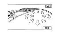
駐車支援ECU12には、車両後部のバンパ中央部に配設されたバックモニタカメラ20、及び、車室内に設けられたディスプレイ22が接続されている。バックモニタカメラ20は、車両後方の所定角度領域における風景を撮影するCCDカメラ等の撮像手段であり、その撮影した画像信号を駐車支援ECU12に供給する。駐車支援ECU12は、リバースシフトスイッチ50及び駐車スイッチ52が共にオン状態となった際に、ディスプレイ22上にバックモニタカメラ20の撮像画像(実画像)を表示させる。このとき、ディスプレイ22上には、図2(車庫入れ駐車用の画面)に示すように、撮像画像上に目標駐車枠が重畳表示される。目標駐車枠は、実際の駐車枠や車両の外形を模した図形であってよく、例えば、その位置及び向きがユーザにより視認可能である形態を有し、車庫入れ駐車(並列駐車)用の表示と縦列駐車用の表示の2種類が用意されてよい。 The parking assist ECU 12 is connected to a
このようにしてディスプレイ22上に表示される目標駐車枠の初期表示位置・向きは、上述の如く測距センサ70の検出結果に基づいて決定された目標駐車位置及び後述する目標駐車方向に対応する。この目標駐車枠の位置・向き(=目標駐車位置・目標駐車方向)は、そのまま、ユーザによる最終的な確定スイッチの操作等により確定されてよい。或いは、目標駐車枠の位置等は、図2に示すように、目標駐車枠を上下左右方向の並進移動及び回転移動させるためのタッチスイッチ等により、確定スイッチの操作前に調整が可能とされてもよい。 The initial display position / orientation of the target parking frame displayed on the
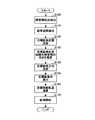
図3は、本実施例の駐車支援ECU12の主要機能を示すブロック図である。図4は、本実施例の駐車支援ECU12により実現される主要処理の流れを示すフローチャートである。 FIG. 3 is a block diagram showing the main functions of the
駐車支援ECU12は、駐車空間検出部42と、目標駐車位置決定部44と、障害物向き推定部46と、目標移動軌跡演算部48とを含む。 The parking assist ECU 12 includes a parking
駐車空間検出部42は、駐車開始位置に至る過程における測距センサ70の検出結果に基づいて、駐車開始位置に至る過程における車両側方周辺の障害物状況(典型的には、他車両の駐車周辺)を検出・把握し(ステップ100)、駐車可能なスペースとして駐車空間を検出する(ステップ110)。尚、測距センサ70による測距は、駐車スイッチ52がオンにされた場合、又は、車速が所定値以下となった場合に実行されてもよい。 Based on the detection result of the
図5は、縦列駐車時の駐車開始位置に至る過程における車両周辺の障害物状況の一例を平面視で示す図である。図5(A)に示す例では、駐車開始位置に至る過程において障害物である車両Z1が一台検出され、駐車空間検出部42は、当該車両Z1の前部から、駐車開始位置での自車後軸中心までを駐車空間として決定する。尚、図5には、測距センサ70の検出結果を示す点列が、車両Z1の外形に沿って示されている。 FIG. 5 is a diagram illustrating an example of an obstacle situation around the vehicle in the process of reaching the parking start position in parallel parking. In the example shown in FIG. 5A, one vehicle Z1, which is an obstacle, is detected in the process of reaching the parking start position, and the parking
目標駐車位置決定部44は、駐車空間検出部42の検出した駐車空間内に目標駐車位置を決定する(ステップ120)。図5(A)に示す例では、目標駐車位置決定部44は、駐車空間検出部42の検出した駐車空間の略真ん中に中心が位置するように目標駐車位置を決定する。また、2台分以上の駐車空間が検出された場合、目標駐車位置決定部44は、図5(B)に示すように、駐車空間検出部42の検出した駐車空間の何れかの側に寄った位置に目標駐車位置を決定してよい。この場合、例えば図5(C)に示すように2台目の車両Z2の一部(例えば2.5mの検出長さ)が検出できた場合には、2台目の車両Z2側の位置に目標駐車位置を決定してよい。この際、余裕分として2台目の車両Z2の後方から所定の距離を確保して目標駐車位置を決定してよい。 The target parking
目標駐車位置決定部44により目標駐車位置が決定されると、障害物向き推定部46は、目標駐車位置の前後又は左右を含む目標駐車位置の両側に存在する障害物のそれぞれの向きを、測距センサ70の検出結果に基づいて推定する(ステップ130)。尚、実際のシステムでは、目標駐車位置は点座標として、例えば駐車空間内における車両の後軸中心が位置すべき点座標として管理されるが、本明細書及び添付の特許請求の範囲において、“目標駐車位置の両側”とは、目標駐車位置に車両を置いた場合の当該車両にとっての“前後又は左右”を意味するものとする。 When the target parking position is determined by the target parking
図6は、目標駐車方向の決定方法を説明するための図であり、縦列駐車時の駐車開始位置にある自車と、目標駐車位置の前後に検出される障害物とを平面視で示す図である。図6に示す例では、1台目の車両Z1は、基準方向に対して角度θ1(本例ではゼロ)で駐車されており、2台目の車両Z2が基準方向に対して角度θ2傾斜して駐車されている。 FIG. 6 is a diagram for explaining a method of determining the target parking direction, and is a diagram illustrating in plan view the host vehicle at the parking start position at the time of parallel parking and obstacles detected before and after the target parking position. It is. In the example shown in FIG. 6, the first vehicle Z1 is parked at an angle θ1 (zero in this example) with respect to the reference direction, and the second vehicle Z2 is inclined at an angle θ2 with respect to the reference direction. Parked.
この場合、障害物向き推定部46は、目標駐車位置の前後に存在する障害物のそれぞれの向き、即ち、車両Z1及び車両Z2の向きを示す角度θ1及びθ2を推定する。典型的には、障害物向き推定部46は、1台目の車両Z1に係る点列データ(図5(A)参照)に対して曲線又は直線を当てはめて近似曲線又は直線を導出し、当該近似曲線等に基づいて、車両Z1の向き(駐車方向)を検出する。 In this case, the obstacle
ここで、本明細書において“車両の駐車方向”とは、当該車両の前後軸方向に対応する。但し、本発明はこの定義に限定されることは無く、車両の左右方向など、車両の向きを表す方向であれば如何なる定義方法であっても同様の効果を得られることは当業者であれば容易に想像可能である。 Here, in the present specification, the “vehicle parking direction” corresponds to the longitudinal axis direction of the vehicle. However, the present invention is not limited to this definition, and those skilled in the art can obtain the same effect by any definition method as long as it is a direction that represents the direction of the vehicle, such as the left-right direction of the vehicle. It can be easily imagined.
一般的な車両の前部は直線で近似でき、車両の側部は直線若しくは曲率の小さい2次曲線で近似できる。従って、車両の前部を直線近似した場合、当該近似直線に直交する方向が、車両の前後軸、即ち車両の駐車方向に対応するものとしてよく、車両の側部を直線近似した場合、当該近似直線の方向が駐車方向に対応するものとしてよく、車両の側部を2次曲線で近似した場合、当該近似した2次曲線の中心軸に直交する方向が駐車方向に対応するものとしてよい。尚、代替的に、主軸が求まるものであれば、2次曲線以外の曲線による近似が適用されてもよく、他の近似図形による近似が適用されてもよい。 The front part of a general vehicle can be approximated by a straight line, and the side part of the vehicle can be approximated by a straight line or a quadratic curve having a small curvature. Therefore, when the front part of the vehicle is linearly approximated, the direction orthogonal to the approximate straight line may correspond to the longitudinal axis of the vehicle, that is, the parking direction of the vehicle. The direction of the straight line may correspond to the parking direction, and when the side portion of the vehicle is approximated by a quadratic curve, the direction orthogonal to the central axis of the approximated quadratic curve may correspond to the parking direction. Alternatively, if a principal axis can be obtained, approximation by a curve other than a quadratic curve may be applied, or approximation by another approximate figure may be applied.
目標駐車位置決定部44は、障害物向き推定部46が推定した目標駐車位置の前後又は左右の障害物のそれぞれの向きに基づいて、当該目標駐車位置に対して如何なる向きで車両を駐車させるか、即ち目標駐車方向を決定する(ステップ140)。図6に示す例では、目標駐車位置決定部44は、車両Z1と車両Z2のそれぞれの向きのなす鋭角側の角度範囲内に目標駐車方向θtgを決定する。即ち、車両Z2は車両Z1に対して角度θ3=θ2−θ1(但し、0<θ3<90)傾斜している状況下では、目標駐車方向θtgは、0<θtg<θ3を満たすように決定される。 The target parking
目標駐車方向θtgは、好ましくは、車両Z1と車両Z2のそれぞれの向きのなす鋭角側の角度範囲内の中間値に決定される。即ち、先の例では、目標駐車方向θtgは、θtg=θ3/2とされる。 The target parking direction θtg is preferably determined to be an intermediate value within an acute angle range formed by the directions of the vehicles Z1 and Z2. That is, in the previous example, the target parking direction θtg is θtg = θ3 / 2.
或いは、目標駐車位置決定部44は、図6に示すように、目標駐車位置の前後に存在する障害物のそれぞれの目標駐車位置側の端点α、βを結ぶ直線Xの方向に基づいて、目標駐車方向を決定してもよい。この決定方法は、測距センサ70の検出結果である点列データの中から基準方向(例えば車両進行方向)で最も端にある点を端点α、βとして導出するものであり(尚、端点α、βは点列データそのものである必要は無く適切に補正されたものであってもよい)、必ずしも障害物の向きを推定することを必要としない。従って、この決定方法は、例えば、2台目の車両Z2に対して十分な長さの点列データが得られない場合や、曲線近似の誤差が大きいと予測される場合等に、代替的に採用されてもよい。或いは、目標駐車位置決定部44は、2つの障害物の向きの差、先の例では車両Z1と車両Z2のそれぞれの向きの差が大きい場合、直線Xの方向に基づいて目標駐車方向を決定し、逆に、2つの障害物の向きの差、先の例では車両Z1と車両Z2のそれぞれの向きの差(θ3)が小さい場合、それぞれの向きのなす鋭角側の角度範囲内に目標駐車方向を決定してもよい。 Alternatively, as shown in FIG. 6, the target parking
尚、この目標駐車方向の決定方法は、車庫入れ駐車の場合に適用することも可能である。この場合、同様に、目標駐車位置の左右に存在する障害物のそれぞれの目標駐車位置側の端点α、βを結ぶ直線Xの方向に基づいて、目標駐車方向が決定される。 This method for determining the target parking direction can also be applied to garage parking. In this case, similarly, the target parking direction is determined based on the direction of the straight line X connecting the end points α and β on the target parking position side of the obstacles present on the left and right of the target parking position.
図7は、車庫入れ駐車の場合における目標駐車方向の決定方法の説明図である。車庫入れ駐車の場合も同様に、障害物向き推定部46は、目標駐車位置の前後に存在する障害物のそれぞれの向き、即ち、車両Z1及び車両Z2の向きを示す角度θ1及びθ2を推定する。この場合、車両Z1及び車両Z2の向きは、それぞれの前部の点列データに基づいて推定されてよい。目標駐車位置決定部44は、障害物向き推定部46が推定した目標駐車位置の左右の障害物のそれぞれの向きに基づいて、目標駐車方向を決定する。図7に示す例では、目標駐車位置決定部44は、車両Z1と車両Z2のそれぞれの向きのなす鋭角側の角度範囲内に目標駐車方向θtgを決定する。即ち、車両Z2は車両Z1に対して角度θ3=θ2−θ1(但し、0<θ3<90)傾斜している状況下では、目標駐車方向θtgは、0<θtg<θ3を満たすように決定される。同様に、目標駐車方向θtgは、好ましくは、車両Z1と車両Z2のそれぞれの向きのなす鋭角側の角度範囲内の中間値に決定される。即ち、先の例では、目標駐車方向θtgは、θtg=θ3/2とされる。 FIG. 7 is an explanatory diagram of a method for determining the target parking direction in the case of garage parking. Similarly, in the case of garage parking, the obstacle
このようにして決定された目標駐車位置及び目標駐車方向は、上述の如く、ディスプレイ22上に目標駐車枠の初期表示位置として表示される(ステップ150)。例えばユーザにより確定ボタンが操作され、目標駐車枠の位置・向き(=目標駐車位置及び目標駐車方向)が確定されると、目標移動軌跡演算部48は、撮像画像上の目標駐車枠の位置に基づいて、当該目標駐車枠の位置に対応する実空間内の位置に車両を導くための目標移動軌跡(例えば後軸中心軌跡)を演算すると共に、目標移動軌跡上の各位置で転舵されるべき車輪の目標転舵角(目標舵角)を演算する(ステップ160)。 The target parking position and the target parking direction thus determined are displayed on the
駐車支援が開始されると(ステップ170)、駐車支援ECU12は、自動誘導制御中、車速センサ18の出力信号から演算した車両移動量と舵角センサ16から得られる舵角位置を用いて自車の車両位置を推定し、推定した車両位置の目標移動軌跡からの偏差に応じた目標舵角を演算し、当該目標舵角を操舵制御ECU30に送信する。操舵制御ECU30は、当該目標舵角を実現するようにモータ32を制御する。尚、モータ32は、ステアリングコラムに設けられ、その回転角によりステアリングシャフトを回転させるものであってよい。 When parking assistance is started (step 170), the
尚、目標移動軌跡演算部48は、舵角センサ16及び車速センサ18の出力信号に基づいて、駐車支援実行中における車両位置を推定演算し、前回演算した目標移動軌跡と、推定した車両位置との差に応じて、今回の目標移動軌跡を演算し、当該目標移動軌跡に基づいて上述の推定車両位置における目標舵角を決定してもよい。この目標移動軌跡の演算は、車両が所定移動距離(例えば、0.5m)だけ移動する毎に実施されてよい。また、このような軌道修正を行う余裕を残しておく為、初回の目標移動軌跡の生成には、車両の最大旋回曲率よりもある程度小さい旋回曲率(例えば、最大旋回曲率の90%までの旋回曲率)が用いられてよい。 The target movement
以上のように本実施例によれば、目標駐車位置の両側に存在する他車の向きを考慮して目標駐車方向が決定されるので、適切な目標駐車方向に基づく駐車支援が可能となる。この結果、目標駐車位置の両側の他車に対して、位置のみならず向きについても適切な関係を確保できる駐車が可能となり、駐車支援制御の有用性や信頼性が向上する。 As described above, according to the present embodiment, since the target parking direction is determined in consideration of the direction of other vehicles existing on both sides of the target parking position, parking support based on an appropriate target parking direction is possible. As a result, it becomes possible to park the other vehicles on both sides of the target parking position so that an appropriate relationship can be secured not only for the position but also for the direction, and the usefulness and reliability of the parking support control are improved.
本実施例において、目標移動軌跡演算部48は、駐車開始位置で目標移動軌跡の演算を行うのに加えて、駐車開始位置に至るまでの車両移動中においても、目標移動軌跡の演算を行ってよい。即ち、目標移動軌跡演算部48は、目標駐車位置決定部44により目標駐車位置及び目標駐車方向が決定された時点から、車両の現在位置に対して目標移動軌跡を演算し始め、適切な目標移動軌跡の演算が可能となって地点で、運転者に車両を停止させるように指示を出すようにしてもよい。或いは、目標移動軌跡演算部48は、目標駐車位置決定部44により目標駐車位置及び目標駐車方向が決定された時点で、適切な目標移動軌跡の演算が可能な駐車開始位置を決定し、当該駐車開始位置まで車両を適切に案内するようにしてもよい。 In this embodiment, the target movement
以上、本発明の好ましい実施例について詳説したが、本発明は、上述した実施例に制限されることはなく、本発明の範囲を逸脱することなく、上述した実施例に種々の変形及び置換を加えることができる。 The preferred embodiments of the present invention have been described in detail above. However, the present invention is not limited to the above-described embodiments, and various modifications and substitutions can be made to the above-described embodiments without departing from the scope of the present invention. Can be added.
例えば、上述の実施例では、測距センサ70は、車両前部の左右両側に設定されているが、それに加えて又はそれに代えて、車両の中央部の左右両側、或いは車両後部の左右両側に設定されてもよい。 For example, in the above-described embodiment, the
また、上述の実施例では、測距センサ70の検出結果に基づいて目標駐車位置及び目標駐車方向が決定されているが、目標駐車位置については、他の因子により決定されてもよく、例えば、駐車スイッチ52が操作された時点の車両位置と特定の相対関係にある位置や、過去の駐車履歴に基づいて推定される位置、過去の移動履歴に基づいて推定される位置であってもよい。 Moreover, in the above-mentioned Example, although the target parking position and the target parking direction are determined based on the detection result of the ranging
また、上述では、説明の都合上、障害物は車両を想定しているが、障害物としては、自転車、二輪車、壁、2つ以上のパイロン等のあらゆる方向性を持つ有体物が想定可能である。例えば、パイロンの場合には、その設置箇所を結ぶ直線の向きを“障害物の向き”としてよい。 In the above description, for the convenience of explanation, the obstacle is assumed to be a vehicle, but as the obstacle, a tangible object having any direction such as a bicycle, a two-wheeled vehicle, a wall, and two or more pylons can be assumed. . For example, in the case of a pylon, the direction of a straight line connecting the installation locations may be referred to as an “obstacle direction”.
10 駐車支援装置
12 駐車支援ECU
16 舵角センサ
18 車速センサ
20 バックモニタカメラ
22 表示モニタ
30 操舵制御ECU
42 駐車空間検出部
44 目標駐車位置決定部
46 障害物向き推定部
48 目標移動軌跡演算部
50 リバースシフトスイッチ
52 駐車スイッチ
70 測距センサ10
16
42 Parking
Claims (6)
Translated fromJapanese目標駐車位置周辺に存在する障害物を検出する手段と、
前記検出結果に基づいて、目標駐車位置の両側に存在する各障害物の向きを推定する手段とを備え、
前記推定した双方の障害物の向きに基づいて、目標駐車位置における車両の向きである目標駐車方向を決定し、該目標駐車方向が実現されるように目標駐車位置までの車両走行を支援することを特徴とする、駐車支援装置。Means for determining a target parking position for parking;
Means for detecting obstacles around the target parking position;
Means for estimating the direction of each obstacle present on both sides of the target parking position based on the detection result;
Based on the estimated directions of both obstacles, a target parking direction that is a vehicle direction at the target parking position is determined, and vehicle travel to the target parking position is supported so that the target parking direction is realized. A parking assistance device characterized by the above.
前記障害物は、目標駐車位置の前後に存在する障害物である、請求項1に記載の駐車支援装置。The parking support device according to claim 1, wherein the parking support device supports parallel parking.
The parking assistance device according to claim 1, wherein the obstacle is an obstacle existing before and after the target parking position.
目標駐車位置周辺に存在する障害物を検出する手段と、
前記検出結果に基づいて、目標駐車位置の両側に存在する障害物のそれぞれの目標駐車位置側の端点を推定する手段とを備え、
前記推定したそれぞれの端点を結ぶ直線の方向に基づいて、目標駐車位置における車両の向きである目標駐車方向を決定し、該目標駐車方向が実現されるように目標駐車位置までの車両走行を支援することを特徴とする、駐車支援装置。Means for determining a target parking position;
Means for detecting obstacles around the target parking position;
Means for estimating the end points on the target parking position side of obstacles present on both sides of the target parking position based on the detection result,
Based on the direction of the straight line connecting the estimated end points, the target parking direction, which is the direction of the vehicle at the target parking position, is determined, and the vehicle travels to the target parking position so that the target parking direction is realized. A parking assistance device, characterized by:
Priority Applications (1)
| Application Number | Priority Date | Filing Date | Title |
|---|---|---|---|
| JP2005005220AJP2006193011A (en) | 2005-01-12 | 2005-01-12 | Parking assistance device |
Applications Claiming Priority (1)
| Application Number | Priority Date | Filing Date | Title |
|---|---|---|---|
| JP2005005220AJP2006193011A (en) | 2005-01-12 | 2005-01-12 | Parking assistance device |
Publications (1)
| Publication Number | Publication Date |
|---|---|
| JP2006193011Atrue JP2006193011A (en) | 2006-07-27 |
Family
ID=36799424
Family Applications (1)
| Application Number | Title | Priority Date | Filing Date |
|---|---|---|---|
| JP2005005220APendingJP2006193011A (en) | 2005-01-12 | 2005-01-12 | Parking assistance device |
Country Status (1)
| Country | Link |
|---|---|
| JP (1) | JP2006193011A (en) |
Cited By (12)
| Publication number | Priority date | Publication date | Assignee | Title |
|---|---|---|---|---|
| WO2008072473A1 (en)* | 2006-12-12 | 2008-06-19 | Toyota Jidosha Kabushiki Kaisha | Parking support device |
| WO2008108243A1 (en)* | 2007-03-08 | 2008-09-12 | Toyota Jidosha Kabushiki Kaisha | Parking assistance device |
| JP2008273495A (en)* | 2007-04-30 | 2008-11-13 | Hyundai Motor Co Ltd | Car parking guidance method |
| KR20130136078A (en)* | 2012-06-04 | 2013-12-12 | 현대모비스 주식회사 | Appartus and method for controlling aotomatic parking |
| WO2014051125A1 (en)* | 2012-09-28 | 2014-04-03 | アイシン精機株式会社 | Parking assistance device, and parking assistance method and program |
| KR101916515B1 (en)* | 2016-07-20 | 2018-11-07 | 현대자동차주식회사 | Method for guiding parking mode in remote automatic parking assist system |
| JP2019006359A (en)* | 2017-06-29 | 2019-01-17 | 株式会社デンソー | Parking support device, parking support system and parking support method |
| CN109466544A (en)* | 2017-09-08 | 2019-03-15 | 法雷奥开关和传感器有限责任公司 | The method for characterizing parking space, parking assistance system and motor vehicles |
| US10830885B2 (en) | 2015-10-06 | 2020-11-10 | Mitsubishi Electric Corporation | Parking mode determining system |
| CN112298166A (en)* | 2019-07-29 | 2021-02-02 | 歌乐株式会社 | Parking assistance device and control method for parking assistance device |
| KR20210136535A (en)* | 2020-05-08 | 2021-11-17 | 현대모비스 주식회사 | Radar System for Vehicle And Control Method Therefor |
| JP2023512513A (en)* | 2020-02-20 | 2023-03-27 | コンチネンタル・オートナマス・モビリティ・ジャーマニー・ゲゼルシャフト・ミト・ベシュレンクテル・ハフツング | parking assist system |
Citations (5)
| Publication number | Priority date | Publication date | Assignee | Title |
|---|---|---|---|---|
| JP2002120677A (en)* | 2000-10-12 | 2002-04-23 | Daihatsu Motor Co Ltd | Parking support system and control method for the same |
| JP2002228734A (en)* | 2001-02-05 | 2002-08-14 | Nissan Motor Co Ltd | Ambient object recognition device |
| JP2002243857A (en)* | 2001-02-14 | 2002-08-28 | Nissan Motor Co Ltd | Surrounding body recognizer |
| JP2004034946A (en)* | 2002-07-08 | 2004-02-05 | Toyota Motor Corp | Image processing device, parking assist device, and image processing method |
| JP2004048295A (en)* | 2002-07-10 | 2004-02-12 | Toyota Motor Corp | Image processing device, parking assist device, and image processing method |
- 2005
- 2005-01-12JPJP2005005220Apatent/JP2006193011A/enactivePending
Patent Citations (5)
| Publication number | Priority date | Publication date | Assignee | Title |
|---|---|---|---|---|
| JP2002120677A (en)* | 2000-10-12 | 2002-04-23 | Daihatsu Motor Co Ltd | Parking support system and control method for the same |
| JP2002228734A (en)* | 2001-02-05 | 2002-08-14 | Nissan Motor Co Ltd | Ambient object recognition device |
| JP2002243857A (en)* | 2001-02-14 | 2002-08-28 | Nissan Motor Co Ltd | Surrounding body recognizer |
| JP2004034946A (en)* | 2002-07-08 | 2004-02-05 | Toyota Motor Corp | Image processing device, parking assist device, and image processing method |
| JP2004048295A (en)* | 2002-07-10 | 2004-02-12 | Toyota Motor Corp | Image processing device, parking assist device, and image processing method |
Cited By (25)
| Publication number | Priority date | Publication date | Assignee | Title |
|---|---|---|---|---|
| WO2008072473A1 (en)* | 2006-12-12 | 2008-06-19 | Toyota Jidosha Kabushiki Kaisha | Parking support device |
| WO2008108243A1 (en)* | 2007-03-08 | 2008-09-12 | Toyota Jidosha Kabushiki Kaisha | Parking assistance device |
| JP2008221894A (en)* | 2007-03-08 | 2008-09-25 | Toyota Motor Corp | Parking assistance device |
| US8285479B2 (en) | 2007-03-08 | 2012-10-09 | Toyota Jidosha Kabushiki Kaisha | Parking assist apparatus |
| JP2008273495A (en)* | 2007-04-30 | 2008-11-13 | Hyundai Motor Co Ltd | Car parking guidance method |
| KR20130136078A (en)* | 2012-06-04 | 2013-12-12 | 현대모비스 주식회사 | Appartus and method for controlling aotomatic parking |
| WO2014051125A1 (en)* | 2012-09-28 | 2014-04-03 | アイシン精機株式会社 | Parking assistance device, and parking assistance method and program |
| JP2014069722A (en)* | 2012-09-28 | 2014-04-21 | Aisin Seiki Co Ltd | Parking support system, parking support method, and program |
| US9741250B2 (en) | 2012-09-28 | 2017-08-22 | Aisin Seiki Kabushiki Kaisha | Parking assist apparatus, parking assist method, and computer program product |
| DE112015007005B4 (en) | 2015-10-06 | 2021-09-30 | Mitsubishi Electric Corporation | Parking mode determination system |
| US10830885B2 (en) | 2015-10-06 | 2020-11-10 | Mitsubishi Electric Corporation | Parking mode determining system |
| KR101916515B1 (en)* | 2016-07-20 | 2018-11-07 | 현대자동차주식회사 | Method for guiding parking mode in remote automatic parking assist system |
| US10137888B2 (en) | 2016-07-20 | 2018-11-27 | Hyundai Motor Company | Method for guiding parking mode in remote automatic parking support system |
| JP2019006359A (en)* | 2017-06-29 | 2019-01-17 | 株式会社デンソー | Parking support device, parking support system and parking support method |
| JP7009796B2 (en) | 2017-06-29 | 2022-01-26 | 株式会社デンソー | Parking support device, parking support system and parking support method |
| CN109466544A (en)* | 2017-09-08 | 2019-03-15 | 法雷奥开关和传感器有限责任公司 | The method for characterizing parking space, parking assistance system and motor vehicles |
| JP2021020571A (en)* | 2019-07-29 | 2021-02-18 | クラリオン株式会社 | Parking support device and control method for parking support device |
| EP3771620A1 (en) | 2019-07-29 | 2021-02-03 | Clarion Co., Ltd. | Parking assistance device and control method of parking assistance device |
| CN112298166A (en)* | 2019-07-29 | 2021-02-02 | 歌乐株式会社 | Parking assistance device and control method for parking assistance device |
| US11465613B2 (en) | 2019-07-29 | 2022-10-11 | Clarion Co., Ltd. | Parking assistance device and control method of parking assistance device |
| JP7346129B2 (en) | 2019-07-29 | 2023-09-19 | フォルシアクラリオン・エレクトロニクス株式会社 | Parking support device and method of controlling the parking support device |
| CN112298166B (en)* | 2019-07-29 | 2024-03-08 | 歌乐株式会社 | Parking support device and control method for parking support device |
| JP2023512513A (en)* | 2020-02-20 | 2023-03-27 | コンチネンタル・オートナマス・モビリティ・ジャーマニー・ゲゼルシャフト・ミト・ベシュレンクテル・ハフツング | parking assist system |
| KR20210136535A (en)* | 2020-05-08 | 2021-11-17 | 현대모비스 주식회사 | Radar System for Vehicle And Control Method Therefor |
| KR102730161B1 (en) | 2020-05-08 | 2024-11-13 | 현대모비스 주식회사 | Radar System for Vehicle And Control Method Therefor |
Similar Documents
| Publication | Publication Date | Title |
|---|---|---|
| JP4179285B2 (en) | Parking assistance device | |
| JP4380655B2 (en) | Parking assistance device and parking assistance method | |
| JP2006189393A (en) | Peripheral object information acquisition device and parking support device using the same | |
| JP4769625B2 (en) | Parking assistance device and parking assistance method | |
| JP4386083B2 (en) | Parking assistance device | |
| JP4432929B2 (en) | Parking assistance device and parking assistance method | |
| JP4432930B2 (en) | Parking assistance device and parking assistance method | |
| EP2055536A1 (en) | Parking support device | |
| JP2008201178A (en) | Parking assistance device | |
| JP5971197B2 (en) | Parking assistance device | |
| JP5082905B2 (en) | Parking assistance device, parking assistance method, and computer program | |
| JP2008296639A (en) | Parking assistance device | |
| JP4613871B2 (en) | Parking assistance device | |
| JP2006193011A (en) | Parking assistance device | |
| JP5983276B2 (en) | Parking assistance device | |
| JP5257138B2 (en) | Parking assistance device and parking assistance method | |
| JP4816512B2 (en) | Driving assistance device | |
| JP4645542B2 (en) | Parking space detection device | |
| JP4941383B2 (en) | Parking assistance device, parking assistance method, and computer program | |
| JP5880858B2 (en) | Parking assistance device | |
| JP4946816B2 (en) | Parking assistance device, parking assistance method, and computer program | |
| JP3885043B2 (en) | Parking assistance device | |
| JP2008290631A (en) | Parking assistance device | |
| JP2014221615A (en) | Parking assisting device | |
| JP2021064160A (en) | Moving object discrimination system |
Legal Events
| Date | Code | Title | Description |
|---|---|---|---|
| A621 | Written request for application examination | Free format text:JAPANESE INTERMEDIATE CODE: A621 Effective date:20071221 | |
| A977 | Report on retrieval | Free format text:JAPANESE INTERMEDIATE CODE: A971007 Effective date:20091228 | |
| A131 | Notification of reasons for refusal | Free format text:JAPANESE INTERMEDIATE CODE: A131 Effective date:20100119 | |
| A02 | Decision of refusal | Free format text:JAPANESE INTERMEDIATE CODE: A02 Effective date:20100601 |