JP2006187323A - Treatment tool and medical treatment instrument - Google Patents
Treatment tool and medical treatment instrumentDownload PDFInfo
- Publication number
- JP2006187323A JP2006187323AJP2004381723AJP2004381723AJP2006187323AJP 2006187323 AJP2006187323 AJP 2006187323AJP 2004381723 AJP2004381723 AJP 2004381723AJP 2004381723 AJP2004381723 AJP 2004381723AJP 2006187323 AJP2006187323 AJP 2006187323A
- Authority
- JP
- Japan
- Prior art keywords
- treatment
- coagulation
- unit
- shape
- temperature
- Prior art date
- Legal status (The legal status is an assumption and is not a legal conclusion. Google has not performed a legal analysis and makes no representation as to the accuracy of the status listed.)
- Granted
Links
- 238000001514detection methodMethods0.000claimsdescription32
- 230000008859changeEffects0.000claimsdescription13
- 238000012546transferMethods0.000claimsdescription6
- 230000015271coagulationEffects0.000abstractdescription97
- 238000005345coagulationMethods0.000abstractdescription97
- 230000007246mechanismEffects0.000abstractdescription10
- 238000010438heat treatmentMethods0.000description49
- 230000005856abnormalityEffects0.000description27
- 238000012937correctionMethods0.000description22
- 230000002159abnormal effectEffects0.000description13
- 238000010586diagramMethods0.000description13
- 230000020169heat generationEffects0.000description7
- 238000009529body temperature measurementMethods0.000description6
- 238000003780insertionMethods0.000description4
- 230000037431insertionEffects0.000description4
- 238000000034methodMethods0.000description4
- WABPQHHGFIMREM-UHFFFAOYSA-Nlead(0)Chemical compound[Pb]WABPQHHGFIMREM-UHFFFAOYSA-N0.000description3
- 229920001343polytetrafluoroethylenePolymers0.000description3
- 239000004810polytetrafluoroethyleneSubstances0.000description3
- 238000007711solidificationMethods0.000description3
- 230000008023solidificationEffects0.000description3
- 210000004204blood vesselAnatomy0.000description2
- 230000000994depressogenic effectEffects0.000description2
- 239000000463materialSubstances0.000description2
- 230000008569processEffects0.000description2
- YCKRFDGAMUMZLT-UHFFFAOYSA-NFluorine atomChemical compound[F]YCKRFDGAMUMZLT-UHFFFAOYSA-N0.000description1
- 230000008901benefitEffects0.000description1
- 239000000919ceramicSubstances0.000description1
- 239000003795chemical substances by applicationSubstances0.000description1
- 230000000694effectsEffects0.000description1
- 229920001971elastomerPolymers0.000description1
- 229910052731fluorineInorganic materials0.000description1
- 239000011737fluorineSubstances0.000description1
- 238000012986modificationMethods0.000description1
- 230000004048modificationEffects0.000description1
- 230000003287optical effectEffects0.000description1
- -1polytetrafluoroethylenePolymers0.000description1
- 239000011347resinSubstances0.000description1
- 229920005989resinPolymers0.000description1
- 229920002379silicone rubberPolymers0.000description1
- 239000004945silicone rubberSubstances0.000description1
- 239000010409thin filmSubstances0.000description1
Images


Classifications
- A—HUMAN NECESSITIES
- A61—MEDICAL OR VETERINARY SCIENCE; HYGIENE
- A61B—DIAGNOSIS; SURGERY; IDENTIFICATION
- A61B17/00—Surgical instruments, devices or methods
- A61B17/32—Surgical cutting instruments
- A61B17/320068—Surgical cutting instruments using mechanical vibrations, e.g. ultrasonic
- A61B17/320092—Surgical cutting instruments using mechanical vibrations, e.g. ultrasonic with additional movable means for clamping or cutting tissue, e.g. with a pivoting jaw
- A—HUMAN NECESSITIES
- A61—MEDICAL OR VETERINARY SCIENCE; HYGIENE
- A61B—DIAGNOSIS; SURGERY; IDENTIFICATION
- A61B17/00—Surgical instruments, devices or methods
- A61B17/28—Surgical forceps
- A61B17/2812—Surgical forceps with a single pivotal connection
- A—HUMAN NECESSITIES
- A61—MEDICAL OR VETERINARY SCIENCE; HYGIENE
- A61B—DIAGNOSIS; SURGERY; IDENTIFICATION
- A61B17/00—Surgical instruments, devices or methods
- A61B17/32—Surgical cutting instruments
- A61B17/320068—Surgical cutting instruments using mechanical vibrations, e.g. ultrasonic
- A61B17/320092—Surgical cutting instruments using mechanical vibrations, e.g. ultrasonic with additional movable means for clamping or cutting tissue, e.g. with a pivoting jaw
- A61B2017/320094—Surgical cutting instruments using mechanical vibrations, e.g. ultrasonic with additional movable means for clamping or cutting tissue, e.g. with a pivoting jaw additional movable means performing clamping operation
- A—HUMAN NECESSITIES
- A61—MEDICAL OR VETERINARY SCIENCE; HYGIENE
- A61B—DIAGNOSIS; SURGERY; IDENTIFICATION
- A61B17/00—Surgical instruments, devices or methods
- A61B17/32—Surgical cutting instruments
- A61B17/320068—Surgical cutting instruments using mechanical vibrations, e.g. ultrasonic
- A61B17/320092—Surgical cutting instruments using mechanical vibrations, e.g. ultrasonic with additional movable means for clamping or cutting tissue, e.g. with a pivoting jaw
- A61B2017/320095—Surgical cutting instruments using mechanical vibrations, e.g. ultrasonic with additional movable means for clamping or cutting tissue, e.g. with a pivoting jaw with sealing or cauterizing means
Landscapes
- Health & Medical Sciences (AREA)
- Surgery (AREA)
- Engineering & Computer Science (AREA)
- Life Sciences & Earth Sciences (AREA)
- Heart & Thoracic Surgery (AREA)
- Nuclear Medicine, Radiotherapy & Molecular Imaging (AREA)
- Mechanical Engineering (AREA)
- Biomedical Technology (AREA)
- Dentistry (AREA)
- Medical Informatics (AREA)
- Molecular Biology (AREA)
- Animal Behavior & Ethology (AREA)
- General Health & Medical Sciences (AREA)
- Public Health (AREA)
- Veterinary Medicine (AREA)
- Surgical Instruments (AREA)
Abstract
Description
Translated fromJapanese本発明は、所定の処置をする処置具及び前記処置具を有する医療用処置装置に関する。 The present invention relates to a treatment tool for performing a predetermined treatment and a medical treatment apparatus having the treatment tool.
従来より、一般に生体組織を加熱し凝固または切開をする医療用の処置具としては、例えば、凝固処置具、バイポーラ処置具等が知られている。 2. Description of the Related Art Conventionally, for example, a coagulation treatment tool, a bipolar treatment tool, and the like are known as medical treatment tools that generally heat a living tissue to perform coagulation or incision.
凝固処置具は、鉗子先端部にヒータを設け、挟み込んだ生体組織を加熱して凝固又は切開するものである。バイポーラ処置具は、一対の鉗子の間に生体組織を挟み込み、その間において高周波電流を流すことにより生体組織を凝固するものである。 The coagulation treatment instrument is provided with a heater at the distal end portion of the forceps, and heats and solidifies or incises the sandwiched biological tissue. In the bipolar treatment instrument, a living tissue is sandwiched between a pair of forceps, and the living tissue is coagulated by flowing a high-frequency current therebetween.
例えば、特開2003−116871号公報には、ヒータおよび高周波電極の両方を搭載して、生体組織の凝固及び切開を効率よく行うための処置具が開示されている。
組織の処置性能は、鉗子刃先の形状および発熱量の影響を受ける。例えば、高い凝固能力を得るためには、鉗子刃先の生体組織との接触面積を大きくした方がよい。一方、組織の切開を行う場合には、鉗子刃先の生体組織との接触面積を小さく形成した方が有利である。
また、対象とする組織部位によって、エネルギ供給量、言い換えると処置具の発熱量を変化させた方が、より確実な処置が可能になる。従って、組織の部位、または処置目的に応じて鉗子を使い分けること、またエネルギ供給量(発熱量)を変化させることが望ましい。The treatment performance of the tissue is affected by the shape of the forceps blade edge and the amount of heat generation. For example, in order to obtain a high coagulation ability, it is better to increase the contact area of the forceps blade tip with the living tissue. On the other hand, when performing tissue incision, it is advantageous to form a contact area between the forceps blade tip and the living tissue to be small.
Further, more reliable treatment can be performed by changing the energy supply amount, in other words, the heat generation amount of the treatment tool, depending on the target tissue site. Accordingly, it is desirable to use different forceps according tothe tissue site or treatment purpose, and to change the energy supply amount (heat generation amount).
しかしながら、実使用時に、前記使い分けのため持ち替えることおよびエネルギ供給量のなど切り替え作業を行うのは煩わしいという問題があった。
本発明は、このような問題に鑑みてなされたものであり、処置の対象または目的に応じた所定の処置が容易にできる処置具および医療用処置装置を提供することを目的にしている。However, in actual use, there is a problem that it is troublesome to carry out switching work such as changing the holding capacity and energy supply amount for proper use.
The present invention has been made in view of such problems, and an object of the present invention is to provide a treatment instrument and a medical treatment apparatus that can easily perform a predetermined treatment according to a target or purpose of treatment.
本発明の処置具は、生体組織を把持する把持部と、該把持部を開閉操作する操作部とを有する処置具であって、操作手段と、前記操作手段の操作に応じて前記把持部の形状を変化させる形状変化手段とを有することを特徴とする。 The treatment tool of the present invention is a treatment tool having a gripping part that grips a living tissue and an operation part that opens and closes the gripping part. And a shape changing means for changing the shape.
本発明によれば、処置の対象または目的に応じた所定の処置が容易にできる処置具を実現させることができる。 ADVANTAGE OF THE INVENTION According to this invention, the treatment tool which can perform the predetermined | prescribed treatment according to the object or objective of treatment easily is realizable.
以下、図面を参照して本発明の実施の形態を説明する。
(第1の実施の形態)
図1から図11は、第1の実施の形態に係り、図1は、医療用処置装置の全体構成を示すシステム構成図、図2は、医療用処置装置に用いられる処置具用制御装置の前面パネル側から見た外観斜視図、図3は、図2に示す処置具用制御装置の背面パネルを示す外観図、図4は、通常(非凝固モード)状態における凝固切開鉗子の全体を示す構成図、図5は、凝固モード状態における処置具の把持部側を示す構成図、図6は、通常(非凝固モード)状態において把持部が組織を把持した状態を示す説明図、図7は、凝固モード状態において把持部が組織を把持した状態を示す説明図、図8は、処置具用制御装置のブロック図、図9は温度補正パターンを示すグラフ図、図10は、医療用処置装置の動作を説明するためのフローチャート図、図11は、図10のフローチャート図に後続するフローチャート図である。Embodiments of the present invention will be described below with reference to the drawings.
(First embodiment)
1 to 11 relate to the first embodiment, FIG. 1 is a system configuration diagram showing the overall configuration of a medical treatment apparatus, and FIG. 2 is a diagram of a control device for a treatment instrument used in the medical treatment apparatus. FIG. 3 is an external perspective view of the treatment instrument control device shown in FIG. 2, and FIG. 4 is an overall view of the coagulation incision forceps in a normal (non-coagulation mode) state. FIG. 5 is a block diagram showing the grasping part side of the treatment instrument in the coagulation mode state, FIG. 6 is an explanatory view showing a state where the grasping part grasps the tissue in the normal (non-coagulation mode) state, and FIG. FIG. 8 is a block diagram of the treatment instrument control device, FIG. 9 is a graph showing a temperature correction pattern, and FIG. 10 is a medical treatment device. FIG. 1 is a flowchart for explaining the operation of FIG. Is a flowchart subsequent to the flowchart of FIG. 10.
本実施の形態の医療用処置装置1は、図1に示すように、後述する(図3に示す)発熱素子35を内蔵する凝固切開鉗子3と、この処置具としての凝固切開鉗子3を着脱自在に接続可能とすると共に、凝固切開鉗子3に電力を供給して駆動制御する処置具用制御装置2とからなる。
凝固切開鉗子3は、延長する接続ケーブル4の基端部に設けたコネクタ5を処置具用制御装置2に着脱自在に接続するようになっている。As shown in FIG. 1, the
The coagulation /
制御装置としての処置具用制御装置2には、フットスイッチ6が接続可能となっている。フットスイッチ6は、凝固切開鉗子3の発熱素子35に対する温度設定手段として、最高温度レベル出力スイッチ7aおよび設定温度レベル出力スイッチ7bの2つのスイッチを有している。尚、本実施の形態においては、フットスイッチ6にこれら2つのスイッチを用意することにより、処置目的に応じた2種類の温度を処置具用制御装置2の前面パネル4aの設定変更をすることなく、即座に出力可能にしている。 A
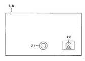
処置具用制御装置2は、図2に示す前面パネル4aおよび図3に示す背面パネル4bを有している。 The treatment
図2に示すように、前面パネル4aには、凝固切開鉗子3のコネクタ5を着脱自在に接続可能なコネクタ受け11を備えている。また、前面パネル4aには、電源をオン/オフする電源スイッチ12と、凝固切開鉗子3の発熱素子35の発熱温度レベルを設定する温度レベルアップスイッチ13aおよび温度レベルダウンスイッチ13bと、スタンバイ状態から出力可能状態に移行させるスタンバイスイッチ14とを有している。さらに、前面パネル4aには、温度レベルアップスイッチ13aおよび温度レベルダウンスイッチ13bにおいて設定した温度レベルを表示する温度レベル表示LED15と、凝固切開鉗子3の発熱素子35に通電中であることを示す出力表示LED16と、スタンバイ状態を表示するために出力不可時に点灯するスタンバイ表示LED17と、凝固切開鉗子3に異常がある場合に点灯する鉗子異常表示LED18と、内部回路に異常がある場合に点灯する電源異常表示LED19とを有している。またさらに、前面パネル4aには、警告音を出力するブザー20を有している。一方、図3に示すように、背面パネル4bには、フットスイッチコネクタ受け部21と、電源インレット22とを備えている。 As shown in FIG. 2, the front panel 4a is provided with a
図4に示すように、凝固切開鉗子3は、棒状部材により構成された第1の鉗子本体23と、この第1の鉗子本体23に枢支部である枢支軸24を介して開閉自在に取り付けられた棒状部材により構成された第2の鉗子本体25とにより主要部が構成されている。 As shown in FIG. 4, the coagulation /
第1の鉗子本体23の先端側に、所定の形状に形成されかつ固定形状刃である第1の把持部(以下、ジョーと称す)26が設けられており、第2の鉗子本体25の先端側に、可変形状刃を有し所定の形状に形成された第2のジョー27が設けられている。尚、第1のジョー26と第2のジョー27とは、対を成して把持部である処置部28を構成しており、この処置部28により生体組織を把持し、後述の所定の処置を可能としている。 A first grasping portion (hereinafter referred to as a jaw) 26 that is formed in a predetermined shape and is a fixed-shaped blade is provided on the distal end side of the
また、第1の鉗子本体23の基端側に、第1のアーム29が設けられており、この第1のアーム29の基端側に、手指挿入用の第1のリング30が設けられている。また、第1のリング30の基端部に、コード接続部34が設けられている。尚、接続ケーブル4は、コード接続部34の基端部から延出している。 Also, a
第2の鉗子本体25の基端側に、第1の鉗子本体23と同様に、第2のアーム31が設けられており、この第2のアーム31の基端側に、手指挿入用の第2のリング32が設けられている。そして、第1、第2のアーム29、31及び第1、第2のリング30、32は、処置部28を構成する一対の第1及び第2のジョー26、27を開閉操作する操作部であるハンドル部(以下、操作部という)33を構成している。尚、第2のアーム31と第2のリング32との間には、後述の切り替えレバー41およびリンク機構42を収納し、かつ操作部33を構成するレバー配置部40を有している。このレバー配置部40は、切り替えレバー41の切り替え操作が容易な位置、具体的には、第2のリング32の近傍に配置されている。 Similar to the first forceps
第1のジョー26は、第2のジョー27に対向する位置に、熱伝達手段である発熱板37が設けられている。詳しくは、第1のジョー26は、第2のジョー27に対向する面に長手軸方向に沿って形成された凹部26aに、断熱部材38を介して発熱板37が実装されている。発熱素子35は、発熱手段であって、発熱板37に接合される。発熱素子35において発生した熱は、発熱板37に伝達されるようになっている。 The
発熱素子35は、例えば、図4に示すように、3つの発熱素子からなり、第1のジョー26本体に内蔵されている。発熱素子35は、例えば、セラミック板に形成された薄膜抵抗体である。これら発熱素子35には、通電するための同軸リード線36の一端がそれぞれに接続され、これら同軸リード線36の他端側は、接続ケーブル4内を挿通され、さらに前記コネクタ5に接続されている。 For example, as shown in FIG. 4, the
発熱板37は、第1のジョー26の長手軸方向に所定の長さに形成され、図6に示すように、その第2のジョー27に対向する面から所定の長さだけ突出して露出して設けられている。発熱板37は、その露出部分が、第1のジョー26の長手軸方向に直交する方向においてほぼ一定の所定幅に形成されている。この発熱板37の露出部分は、生体組織を加熱して、凝固切開等の処置をする際の処置面を構成している。
尚、断熱部材38は、例えばポリテトラフルオロエチレン(PTFE)等の、熱伝導率が低くかつ耐熱性の高い材料からなる。The
The
一方、前記第2のジョー27は、前記第1のジョー26の発熱板37と対向する位置に受け部材39を配置し、発熱板37と受け部材39との間に生体組織を挟んで弾性的に把持可能としている。そして、前記操作部33の操作により、図6に示すように、第2のジョー27および第1のジョー26が閉じていくことによって、第1のジョー26の発熱板37と、第2のジョー27の受け部材39に挟まれた生体組織が発熱板37の熱によって凝固切開などがされるようになっている。尚、受け部材39は、例えばシリコーンゴムやフッ素ゴム、またはPTFE等の樹脂材料から形成されている。 On the other hand, the
また、第2のジョー27は、第1のジョー26の発熱板37に対向する位置に開口した可動空間27aと、基端側に可動空間27aと連通する退避空間27bとを有している。第2のアーム31には、退避空間27bに連通し退避空間27bより細径のワイヤ挿通孔31aが設けられている。ワイヤ挿通孔31aの基端側は、レバー配置部40内部に形成された可動空間40aに連通している。可動空間40aには、この可動空間40aから突出し、先端にリング部を有する切り替えレバー41、およびリンク機構42が配置されている。 The
受け部材39は、可動空間27aに、第2のジョー27の長手軸方向に直交する方向であって第1のジョー26に向かう方向に進退可能に配置されている。この可動空間27aには、可動プレート43が配置可能であり、また、この可動プレート43は、前記ワイヤ挿通孔31a内を挿通されたガイドワイヤ42aの先端部が連結されている。ガイドワイヤ42aの基端部は、操作部33に設けられた切り替えレバー41にリンク機構42を介して接続されている。リンク機構42は、切り替えレバー41の途中に設けられた支点ピン41aを支点にしてガイドワイヤ42aを第2の鉗子本体25の長手軸方向に進退させる役割を有しており、その動きに連動して可動プレート43は、第2のジョー27の長手軸方向に進退するようになっている。以上のように、可動プレート43、ガイドワイヤ42a、リンク機構42および切り替えレバー41は、操作手段を構成している。
尚、可動プレート43は、ガイドワイヤ42aにより先端側に押され、退避空間27bから可動空間27aに進入し受け部材39を容易に押し上げることができるように、先端部の受け部材39側の面がテーパー状に形成され、先端部が細くなっている。また、可動プレート43は、退避空間27bの基端側壁面に当接し、ワイヤ挿通孔31a内には進入できないようになっている。The receiving
The
また、受け部材39は、可動プレート43が退避空間27bに移動し、受け部材39の可動空間27a内に存在しない時に、第2のジョー27の内部底面側に受け部材39を移動させる力を有する図5および図7に示す4つのバネ44が、それぞれ4つのベースプレート45を介して可動空間27a内に固定されている。言い換えると、受け部材39を所定位置において支える4つのバネ44の他端部をそれぞれ固定する4つのベースプレート45が、可動空間27aにあって、第2のジョー27の内部底面に固定されている。 Further, the receiving
また、図4および図6に示すように、受け部材39は、可動プレート43が可動空間27aに位置する状態において、第1のジョー26側に押し上げられ、第1のジョー26および第2のジョー27が閉じたときに第2のジョー27の第1のジョー26に対向する面と同一平面を構成し、組織の受け部となる。一方、図5および図7に示すように、受け部材39は、可動プレート43が退避空間27bに位置する状態において、バネ44によってベースプレート45側に引きつけられる。従って、第2のジョー27には、第1のジョー26と対向する面に凹形状をした組織の受け部が形成される。以上のように、受け部材39およびバネ44は、第2のジョー27の形状、言い換えると生体組織を受ける表面積を変化させる形状変化手段を構成している。 As shown in FIGS. 4 and 6, the receiving
また、ガイドワイヤ42aの基端側には、受け部材39の移動位置を検知する形状変化検知手段としての切り替え検知センサ46が所定位置に設けられている。具体的には、切り替え検知センサ46は、受け部材39が配置された可動空間27aから、可動プレート43が脱する位置まで移動した時に、ガイドワイヤ42aの基端部を検知する。また、切り替え検知センサ46は、図示しない例えばリード線に接続され、前記接続ケーブル4およびコネクタ5を介して、前記処置具用制御装置2に接続されるようになっている。
尚、切り替え検知センサ46は、感圧センサ、マイクロスイッチ(以下、スイッチはSWと略す)、フォトインタラプタ、リードSWなど光学的、または電子気的手段などの物理変化を検出できるものであればよい。Further, a switching
The switching
また、切り替え検知センサ46は、以上のような有線式のものに代えて、無線式センサとし、検知した信号を無線により処置具用制御装置2へ送信するようにしてもよい。 Further, the switching
よって、図5および図7に示すように、可動プレート43が可動空間27aを脱した状態において、受け部材39は、縮んだバネ44を介してベースプレート45に近接する位置まで移動し、生体組織50と発熱板37との接触面積を増大させることが可能なようになっている。Therefore, as shown in FIGS. 5 and 7, in a state where the
図8に示すように、コネクタ5は、その基端部にコネクタ端子5aを有する。コネクタ端子5aは、前記3つの発熱素子35の端部と接続される端子および切り替え検知センサ46から発信される凝固モード信号を出力する端子とを有している。 As shown in FIG. 8, the
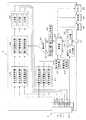
また、前記処置具用制御装置2は、発熱素子35の各々の状態が正常であるか否かを検出する素子状態検出部52と、発熱素子35の各々の温度を測定する素子温度測定部53と、素子温度測定部53において測定した各発熱素子35の測定データ、および後述する温度設定部56から入力される補正後温度設定値を比較して各発熱素子35への出力を素子毎に決定する素子温度制御部54とを有している。さらに、処置具用制御装置2は、素子温度制御部54および制御手段を構成する後述する制御部58の制御信号に基づいて前記発熱素子35各々に電力の出力を行う出力部55と、素子温度制御部54に設定データを出力する温度設定部56と、素子状態検出部52において検出した発熱素子35の状態により鉗子3の異常を判別する鉗子異常判別部57と、フットスイッチ6から入力される信号および素子状態検出部52から入力される信号などに基づき、温度設定部56を制御する制御部58とを有している。 The treatment
さらに、処置具用制御装置2は、補正部62、補正パターン記憶部63、操作部64、電源異常判別部65、表示部66、フットスイッチ入力部67および凝固モード信号入力部68などを有している。 Furthermore, the treatment
補正部62は、切り替え検知センサ46が作動した時には、切り替え検知センサ46が発信する凝固モード信号により、補正パターン記憶部63の補正パターンに基づいて温度補正値を決定する。また、切り替え検知センサ46が作動していない時には、操作部64により入力された設定温度が、制御部58、および温度設定部56を経て補正部62へ出力される。The correction unit 62 determines the temperature correction value based on the correction pattern in the correction
前記素子温度制御部54は、各素子の測定温度と補正温度との温度差に比例した信号を出力部55に出力する。素子温度測定部53は、発熱素子35の抵抗値が温度変化によって変化することを利用して温度測定を行う。すなわち、素子温度測定部53は、抵抗値検出機能として発熱素子35の抵抗値変化によって変化する発熱素子35に流れる電流値および発熱素子にかかる電圧値を測定することにより発熱素子の抵抗値を検出し、この検出した抵抗値により発熱素子35の温度を算出するようになっている。 The element
前記素子状態検出部52は、素子温度測定部53と同様の抵抗値検出機能を有している。この素子状態検出部52は、電流値および電圧値を測定することにより、発熱素子35の抵抗値を検出し、検出した抵抗値が予め決められた正常範囲内にあるか否かを判断する。素子状態検出部52は、測定した抵抗値が例えば、10Ωから100Ωの範囲内にある場合には正常と判断し、一方、測定した抵抗値が前記範囲以外の値である場合には、異常と判断するようになっている。そして、素子状態検出部52は、この検出結果を前記鉗子異常判別部57に出力するようになっている。鉗子異常判別部57は、全ての発熱素子35が正常であれば正常と判断し、一つ以上の発熱素子35の異常が検出された場合には、異常と判断する。 The element
前記制御部58は、鉗子異常判別部57が正常と判断している場合には、鉗子異常表示LED18を消灯させ、また、前記ブザー20を停止させている。また、制御部58は、鉗子異常判別部57が異常と判断している場合には、鉗子異常表示LED18を点灯させ、また、ブザー20を鳴らさせるようになっている。 When the forceps
尚、鉗子異常状態の時には、強制的にスタンバイ状態に移行され、また、スタンバイスイッチ14を押しても出力可能状態には移行しない。よって、フットスイッチ6を押しても発熱素子35への出力は行われない。 When the forceps is in an abnormal state, the state is forcibly shifted to the standby state, and even if the
凝固切開鉗子3は、前記発熱素子35の温度設定については、温度レベルアップスイッチ13a、および温度レベルダウンスイッチ13bの操作により行う。その温度レベルは、例えば、レベル1から5までの五段階があり、レベル1から5は予め例えば160℃から240℃の間において、例えば20℃間隔に設定されている。 The coagulation /
制御部58は、温度レベルアップスイッチ13aおよび温度レベルダウンスイッチ13bにより入力操作される温度設定、並びに前記フットスイッチ6により入力操作される設定温度レベル出力、もしくは最高温度レベル出力によって、温度設定部56に設定温度を出力するようになっている。具体的には、例えば処置具用制御装置2が、温度レベルアップスイッチ13aおよび温度レベルダウンスイッチ13bによりレベル3、すなわち200℃に設定されているとする。ここで、最高温度レベル出力スイッチ7aが押された場合には、設定レベルに関係なく最高レベルであるレベル5、すなわち240℃を温度設定部56に出力する。一方、設定温度レベル出力スイッチ7bが押された場合には、設定されていたレベル3、すなわち200℃を、温度設定部56に出力する。尚、以上の動作は、凝固切開鉗子3の切り替え検知センサ46は作動しておらず、いわゆる通常(非凝固モード)状態における動作である。
一方、凝固切開鉗子3の切り替え検知センサ46が作動し、凝固モード信号が入力された(凝固モード状態の)場合には、設定温度レベル出力スイッチ7bにかかわらず、常に、例えば図9に示す補正パターンに基づく温度を補正部62に出力する。図9に示す補正パターンの例では、所定の上限温度から所定の下限温度まで、所定時間(十数秒)の間に段階的に温度を下げている。The
On the other hand, when the switching
また、前記制御部58には、電源異常判別部65が接続されている。電源異常判別部65には、処置具用制御装置2内部の異常発熱を監視し、異常発熱を検出した場合には、制御部58に異常信号を送信する。そして、制御部58は、直ちに出力部の出力を停止させる。このとき、制御部58は、電源異常表示LED19を点灯し、ブザー20を鳴らして異常を告知する。また、出力可能状態の時に、電源異常が発生した場合には、制御部58は強制的にスタンバイ状態に移行させ、スタンバイ表示LED17を点灯させる。また、制御部58は、スタンバイ状態、および出力可能状態を切り替える機能を有する。 In addition, a power supply
スタンバイ状態においては、凝固切開鉗子3への出力を禁止し、出力許可状態においては、凝固切開鉗子3への出力を可能に言い換えると許可する。よって、操作者は、出力を行いたい場合には、スタンバイスイッチ14の操作により出力可能モードに移行することが必要である。 In the standby state, output to the coagulation /
処置具用制御装置2が異常状態、またはその電源が異常な状態であることを検出している場合には、スタンバイ状態に強制移行され、前記異常状態が解除されない限り、スタンバイスイッチ14を操作しても出力可能状態に移行させることはない。また、異常状態から自然復帰したとしても、自動的に出力可能状態に復帰させることはなく、出力を行う際には、再度スタンバイスイッチ14を操作して、出力可能状態に移行することが必要である。 When the treatment
また、前記制御部58は、出力中には、フットスイッチ6のいずれのスイッチにより出力が行われているのかを区別するため、異なった方法により操作者への告知を行う。
それらの告知方法としては、具体的には、最高温度レベル出力スイッチ7aによる出力時には、ブザー20を連続的に鳴らし出力表示LED16を点灯させて操作者へ知らせる。また、設定温度レベル出力スイッチ7bによる出力時には、ブザー20の間欠音により操作者へ知らせる。一方、凝固モードシグナルが入力されている時には、長い間欠音の後、連続音へ変化させて操作者へ知らせる。尚、ブザー20が発する音の違いを出すために、音の周波数を変調させてもよい。Further, during the output, the
Specifically, as a notification method, at the time of output by the maximum temperature level output switch 7a, the
尚、操作部64は、前述した処置具用制御装置2の前面パネル4aに設けられた温度レベルアップスイッチ13aなどの各種スイッチである。また、表示部66は、処置具用制御装置2の前面パネル4aに設けられた各表示LEDを示している。 The operation unit 64 is various switches such as the temperature level up switch 13a provided on the front panel 4a of the treatment
以上のように構成された医療用処置装置1の作用について、図10および図11のフローチャートを用いて説明する。 The operation of the
まず、図10のステップS1において、電源スイッチ12をオンにして、医療用処置装置1全体を起動する。
次に、ステップS2において、処置具用制御装置2のコネクタ受け11に凝固切開鉗子3を接続する。すると、ステップS3において、処置具用制御装置2は、接続された凝固切開鉗子3の発熱素子35の状態を検出する。First, in step S1 of FIG. 10, the
Next, in step S <b> 2, the coagulation /
ここで、凝固切開鉗子3に設けられた発熱素子35が、仮に、全て正常であるとする。その場合は、鉗子異常判別部57は異常信号を発生せず、ステップS3でYESとなり、操作者は次の操作に移ることができる。
もし、凝固切開鉗子3の発熱素子35のうち、一つでも異常があった場合、ステップS3でNOとなり、ステップS4において、鉗子異常判別部57は鉗子異常を発生し、鉗子異常表示LED18を点灯し、ブザー20を鳴らす。また、制御部58は、出力を禁止する。鉗子異常状態は凝固切開鉗子3を交換するまで発生し続ける。ステップS4Aにおいて、異常のない凝固切開鉗子3が接続されると、ステップS5に進み、処置具用制御装置2はスタンバイ状態に移行する。そして、ステップS6において、温度レベルアップスイッチ13aおよび温度レベルダウンスイッチ13bを操作して温度レベルを設定する。ここでは、温度レベルは、3に設定されていたとする。その後、処置したい生体組織を凝固切開鉗子3により把持する。ここで、スタンバイスイッチ14が押されると(ステップS7)、制御部58は、スタンバイ状態を解除し、スタンバイ表示LED17を消灯させ、出力可能な状態とする。Here, it is assumed that the
If any one of the
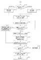
ステップS8において、フットスイッチ6のいずれかのスイッチが押された(Yesの)場合、ステップS9において出力可能状態であれば、後続の図11に示すフローチャートに示すように、発熱素子35への通電が開始され、出力が開始されることとなる。 If any switch of the
図11に示すステップS10において、フットスイッチ6のいずれのスイッチが押されたのかにより、後続する温度設定の処理が異なる。 In step S10 shown in FIG. 11, the subsequent temperature setting process differs depending on which switch of the
フットスイッチ6の最高温度レベル出力スイッチ7aが押された(ステップS10aの)場合、設定温度は最高レベル240℃になる。一方、設定温度レベル出力スイッチ7bが押された(ステップS10bの)場合、設定されていたレベル3、つまり設定温度は200℃になる。
ここでは、仮に、設定温度レベル出力スイッチ7bが押されたとする。制御部58は、設定温度200℃を温度設定部56に出力する。このとき、前面パネル4aには、出力表示LED16が点灯すると共に、ブザー20が音を鳴らす(ステップS11)と共に、発熱素子35の温度測定を開始する(ステップS12)。When the maximum temperature level output switch 7a of the
Here, it is assumed that the set temperature level output switch 7b is pressed. The
ステップS12における温度測定の開始後は、ステップS13において、凝固モード信号の可否を検出する。 After the start of temperature measurement in step S12, whether or not a coagulation mode signal is possible is detected in step S13.
凝固モード信号が入力された場合には、ステップS14において、図9に示す凝固モード補正パターンを補正パターン記憶部63から呼び出す。ステップS15において、呼び出された凝固モード補正パターンと発熱素子35の測定温度とに基づき、制御信号を決定し、ステップS16において、その制御信号に応じて出力を行う。
尚、凝固モードシグナルが入力されていない場合には、ステップS17において、ステップS10aまたはステップS10bにより設定された設定温度と、発熱素子35の測定温度とに基づき、制御信号を決定する。When the coagulation mode signal is input, the coagulation mode correction pattern shown in FIG. 9 is called from the correction
If the coagulation mode signal is not input, a control signal is determined in step S17 based on the set temperature set in step S10a or step S10b and the measured temperature of the
ここで、凝固モード信号入力、つまり凝固モード設定のためのフローを説明する。 凝固モード設定を行うためには、まず、凝固切開鉗子3に設けられた切り替えレバー41を操作し、可動プレート43が受け部材39から外れる位置、具体的には退避空間27bに収まるまで移動させる。それにより、ガイドワイヤ42aの基端部が切り替え検知センサ46により検知される。その検知がなされると、切り替え検知センサ46は、凝固モード信号を処置具用制御装置2へ送信する。 Here, the flow for coagulation mode signal input, that is, for setting the coagulation mode will be described. In order to set the coagulation mode, first, the switching
その凝固モード信号により、補正パターン記憶部63から補正パターンが呼び出され、発熱素子35の測定温度と補正パターンに基づき制御信号が決定される。この時、凝固切開鉗子3の処置部28においては、以下のことが生じている。切り替えレバー41を操作することにより、可動プレート43が受け部材39の所定の配置位置から外れると、受け部材39はバネ44の弾性力、つまり縮もうとする力によりベースプレート45に近接する位置まで沈み込む。その状態において、操作部33を操作し、生体組織50を把持すると、図7に示すように、受け部材39および第2のジョー27の可動空間27aの両壁面により形成される受け部には、発熱板37を取り囲むように生体組織50が配置され、生体組織50と発熱板37の接触面積が増大し、その結果、生体組織の凝固面積が増大する。その状態において、補正パターンに基づき凝固に最適な温度制御が行われることにより、確実な凝固切開が行われる。 Based on the coagulation mode signal, a correction pattern is called from the correction
また、小さな血管など、強力な凝固が必要ではない組織を処置する場合、言い換えると切開を優先した処置の場合には、切り替えレバー41を操作し、切り替え検知センサ46の検出位置からガイドワイヤ42aの基端部を先端側へ移動させ、凝固モードを解除する。 In the case of treating a tissue such as a small blood vessel that does not require strong coagulation, in other words, in the case of treatment that prioritizes incision, the switching
そのとき、凝固切開鉗子3の処置部28では、以下のことが生じている。
ガイドワイヤ42aが凝固切開鉗子3の先端側に移動することにより、可動プレート43が前方に押し出される。可動プレート43の先端部は、テーパー状に形成されているため、可動プレート43が先端側に移動するのに伴い、受け部材39は可動プレート43に押し上げられてゆく。At that time, the following occurs in the
As the guide wire 42a moves to the distal end side of the coagulation /
図6に示すように、可動プレート43が初期位置まで戻された(非凝固モード)状態では、受け部材39の第1のジョー26に対向する面は、可動空間27aの開口部両側に位置しかつ第1のジョー26と対向する第2のジョー27の壁面と、同一平面を構成するまで押し上げられて受け部を形成し、小さな血管など、強力な凝固を必要としない組織の凝固切開に最適な形状に変化する。すなわち、非凝固モードにおいて、この受け部は、凝固モードにおいて形成された受け部よりも、表面積が小さくなり、発熱板37の第2のジョー側の面のみが主に組織50と接触することになり、組織50と発熱板37の接触面積が縮小している。 As shown in FIG. 6, when the
尚、図11に示すステップS18において、凝固モード設定時、非設定時ともフットスイッチ6の押し下げがあったか否かを常に検出し、フットスイッチ6が押し下げられている場合には、ステップS19において、補正値を更新する。その更新補正値と発熱素子35の測定温度に基づき出力制御を行う(S12からS16)。 In step S18 shown in FIG. 11, it is always detected whether or not the
また、ステップS18において、凝固モード設定時、非設定時ともフットスイッチ6の押し下げを常に検出し、フットスイッチ6が解除された場合には、ステップS20において、出力表示LED16を消灯しブザー20を停止すると共に、ステップS21において、出力を停止する。 Further, in step S18, when the coagulation mode is set or not, the depression of the
前述のように、凝固切開鉗子3の切り替えレバー41およびリンク機構42の操作に連動して第2のジョー27の形状が変化、言い換えると、第2のジョー27と組織50との接触可能な面積が変化する。 As described above, the shape of the
本実施の形態の凝固切開鉗子3によれば、処置の対象または目的に応じた所定の処置が容易にできる。所定の処置としては、例えば凝固切開をする際に、凝固を必要とする場合に対しても、一方、強力な凝固を必要としない場合に対しても、それらに合わせた処置を容易にできる。また、本実施の形態の医療用処置装置1によれば、処置の対象または目的に応じて、エネルギ供給量、言い換えると凝固切開鉗子3の発熱温度を変化させ、より確実な処置ができる。 According to the coagulation /
(第2の実施の形態)
図12から図15は、第2の実施の形態に係り、図12は、通常(非凝固モード)状態における凝固切開鉗子の把持部側を示す構成図、図13は、通常(非凝固モード)状態における凝固切開鉗子の縦断面を示す説明図、図14は、凝固モード状態における凝固切開鉗子の縦断面を示す説明図、図15は、凝固モード状態における凝固切開鉗子の把持部側を示す構成図である。
本実施の形態の医療用処置装置は、凝固切開鉗子73および第1の実施の形態と同じ処置具用制御装置2を有している。凝固切開鉗子73は、第1の実施の形態と異なり、前記第1のジョー26が可変形状刃を有し、前記第2のジョー27が固定形状刃を有している。その他、第1の実施の形態と同様の構成要素は、同じ符号を付して説明を省略する。(Second Embodiment)
FIGS. 12 to 15 relate to the second embodiment, FIG. 12 is a configuration diagram showing the gripping portion side of the coagulation incision forceps in a normal (non-coagulation mode) state, and FIG. 13 is a normal (non-coagulation mode). FIG. 14 is an explanatory diagram showing a longitudinal section of the coagulation / incision forceps in the coagulation mode state, and FIG. 15 is a diagram showing a gripping side of the coagulation / incision forceps in the coagulation mode state. FIG.
The medical treatment apparatus according to the present embodiment includes the coagulation /
本実施の形態の凝固切開鉗子73は、図12および図15に示すように、第1のジョー26の前記断熱部材38に発熱板37を固定している。断熱部材38の内部には、発熱板37の側面に隣接しかつ第2のジョー27側に開口する前記可動空間27aと、この可動空間27aに連通する退避空間27bとが設けられている。また、発熱板37には、図示しない前記発熱素子35が第1の実施の形態と同様に設けられている。 As shown in FIGS. 12 and 15, the coagulation /
発熱板37の側面には、可動空間27a内に、熱伝導性の良い補助発熱板70が、第1のジョー26の長手軸方向に直交する方向に、発熱板37に接触して進退自在に配置されている。補助発熱板70に固定された2つのバネ44の一端は、第1のジョー26の内部底面に2つのベースプレート45を介してそれぞれ固定されている。言い換えると、2つのバネ44の他端は、第1のジョー26の内部底面に固定された2つのベースプレート45にそれぞれ固定されている。発熱板37および補助発熱板70は、熱伝達手段としての熱伝達部を構成する。 On the side surface of the
また、補助発熱板70は、通常(非凝固モード)状態において、バネ44により前記ベースプレート45に引きつけられるようになっている。さらに、補助発熱板70は、内部側の面に、前記可動プレート43が、第1のジョー26の長手軸方向に進退自在に配置されている。補助発熱板70およびバネ44は、形状変化手段を構成している。
尚、前記切り替えレバー41、リンク機構42および切り替え検知センサ46は、第1のアーム29および第1のリング30の間に設けた前記レバー配置部40内に設けられている(図12および図15に図示せず)。切り替え検知センサ46は、接続ケーブル4およびコネクタ5を介して処置具用制御装置2に接続されるようになっている。The auxiliary
The switching
可動プレート43は、前記ガイドワイヤ42aを介して切り替えレバー41およびリンク機構42の動きに連動して進退する。可動プレート43が可動空間27a側に移動すると、図14に示すように、補助発熱板70を発熱板37と接触させた状態にして押し上げることができるようになっている。その状態が、凝固モードとなり、図14に示すように、発熱板37に隣接して補助発熱板70が配置されることにより、第1のジョー26の形状が変化し、生体組織50との接触可能な面積が増大する。一方、非凝固モード状態においては、図13に示すように、第1のジョー26から突出しているのは発熱板37のみであり、生体組織50との接触可能な面積も狭くなっている。従って、補助発熱板70は、前記熱伝達手段と共に形状変化手段をも構成する。
非凝固モード状態の時、切り替えレバー41の基端側に設けられた切り替え検知センサ46に検知される位置に、ガイドワイヤ42aの基端部が移動する。The
In the non-solidification mode state, the proximal end portion of the guide wire 42a moves to a position detected by the switching
一方、第2のジョー27には、図13および図14に示すように、発熱板37と対向する位置に前記受け部材39を固定している。 On the other hand, the receiving
前記構成によれば、切り替えレバー41の操作により、凝固切開鉗子73の図示しない発熱素子35の熱を伝える発熱部の形状が変化、言い換えると、第1のジョー26と生体組織50との接触可能な面積が変化して、凝固切開する組織に最適な熱伝達部の形状、および前記処置具用制御装置2からエネルギ出力状態を作り出す。その他、凝固モードおよび非凝固モード状態における処置具用制御装置2による制御は第1の実施の形態と同様であり、説明を省略する。 According to the above configuration, the shape of the heat generating portion that transmits the heat of the heat generating element 35 (not shown) of the
本実施の形態では、第1の実施の形態と同様の効果が得られる。 In the present embodiment, the same effects as in the first embodiment can be obtained.
なお、本実施の形態では、固定形状刃の第2のジョー27に代えて、第1の実施の形態と同じ可変形状刃である第2のジョー27を設け、さらにレバー配置部40を加えてもよい。すなわち、2つの形状可変手段と2つの操作手段とを搭載することとなる。 In this embodiment, instead of the
さらになお、各実施の形態では、一方のジョーにのみ発熱板37および発熱素子35を設けたが、両方のジョーに発熱板37および発熱素子35を設けてもよい。 なお、本発明は、以上述べた実施形態のみに限定されるものではなく、発明の要旨を逸脱しない範囲で種々変形実施可能である。 Furthermore, in each embodiment, the
1…医療用処置装置,2…処置具用制御装置,3…凝固切開鉗子,27…第2のジョー,28…処置部,33…操作部,39…受け部材,41…切り替えレバー,42…リンク機構,42a…ガイドワイヤ,43…可動プレート
代理人 弁理士 伊藤 進DESCRIPTION OF
Claims (7)
Translated fromJapanese操作手段と、
前記操作手段の操作に応じて前記把持部の形状を変化させる形状変化手段とを有することを特徴とする処置具。A treatment tool having a gripping part for gripping a living tissue and an operation part for opening and closing the gripping part,
Operation means;
A treatment instrument comprising: shape changing means for changing the shape of the grip portion in accordance with an operation of the operation means.
前記処置具は、操作手段と、該操作手段の操作に応じて前記把持部の形状を変化させる形状変化手段と、前記形状変化手段の形状が変化したことを検知する形状変化検知手段とを有し、
前記制御装置は、前記形状変化検知手段が検知した形状変化に応じた前記制御を行う制御手段を有することを特徴とする医療用処置装置。A medical treatment device comprising a treatment tool comprising a grasping part for grasping a living tissue and an operation part for opening and closing the grasping part, and a control device for controlling the treatment tool,
The treatment instrument includes an operation unit, a shape change unit that changes the shape of the gripper according to an operation of the operation unit, and a shape change detection unit that detects that the shape of the shape change unit has changed. And
The medical treatment apparatus, wherein the control device includes a control unit that performs the control according to the shape change detected by the shape change detection unit.
The said control means controls the said temperature so that it may become predetermined | prescribed preset temperature, when the said shape change detection means detects that the area which can contact is reduced. Medical treatment device.
Priority Applications (1)
| Application Number | Priority Date | Filing Date | Title |
|---|---|---|---|
| JP2004381723AJP4671685B2 (en) | 2004-12-28 | 2004-12-28 | Medical treatment device |
Applications Claiming Priority (1)
| Application Number | Priority Date | Filing Date | Title |
|---|---|---|---|
| JP2004381723AJP4671685B2 (en) | 2004-12-28 | 2004-12-28 | Medical treatment device |
Publications (2)
| Publication Number | Publication Date |
|---|---|
| JP2006187323Atrue JP2006187323A (en) | 2006-07-20 |
| JP4671685B2 JP4671685B2 (en) | 2011-04-20 |
Family
ID=36795055
Family Applications (1)
| Application Number | Title | Priority Date | Filing Date |
|---|---|---|---|
| JP2004381723AExpired - Fee RelatedJP4671685B2 (en) | 2004-12-28 | 2004-12-28 | Medical treatment device |
Country Status (1)
| Country | Link |
|---|---|
| JP (1) | JP4671685B2 (en) |
Cited By (2)
| Publication number | Priority date | Publication date | Assignee | Title |
|---|---|---|---|---|
| WO2019092822A1 (en)* | 2017-11-08 | 2019-05-16 | オリンパス株式会社 | Treatment tool |
| CN115890509A (en)* | 2022-12-02 | 2023-04-04 | 广州市天河诺亚生物工程有限公司 | Tongue forceps capable of measuring temperature |
Citations (3)
| Publication number | Priority date | Publication date | Assignee | Title |
|---|---|---|---|---|
| JP2001190564A (en)* | 2000-01-12 | 2001-07-17 | Olympus Optical Co Ltd | Medical treatment instrument |
| JP2001353165A (en)* | 2000-06-15 | 2001-12-25 | Olympus Optical Co Ltd | Operation instrument |
| JP2002136525A (en)* | 2000-10-30 | 2002-05-14 | Olympus Optical Co Ltd | Surgical instrument |
- 2004
- 2004-12-28JPJP2004381723Apatent/JP4671685B2/ennot_activeExpired - Fee Related
Patent Citations (3)
| Publication number | Priority date | Publication date | Assignee | Title |
|---|---|---|---|---|
| JP2001190564A (en)* | 2000-01-12 | 2001-07-17 | Olympus Optical Co Ltd | Medical treatment instrument |
| JP2001353165A (en)* | 2000-06-15 | 2001-12-25 | Olympus Optical Co Ltd | Operation instrument |
| JP2002136525A (en)* | 2000-10-30 | 2002-05-14 | Olympus Optical Co Ltd | Surgical instrument |
Cited By (2)
| Publication number | Priority date | Publication date | Assignee | Title |
|---|---|---|---|---|
| WO2019092822A1 (en)* | 2017-11-08 | 2019-05-16 | オリンパス株式会社 | Treatment tool |
| CN115890509A (en)* | 2022-12-02 | 2023-04-04 | 广州市天河诺亚生物工程有限公司 | Tongue forceps capable of measuring temperature |
Also Published As
| Publication number | Publication date |
|---|---|
| JP4671685B2 (en) | 2011-04-20 |
Similar Documents
| Publication | Publication Date | Title |
|---|---|---|
| EP2868283B1 (en) | Therapeutic treatment device with heat transfer units and with means for control based on their temperatures | |
| EP2653125B1 (en) | Medical treatment appartus and method of controlling the same | |
| JP5624841B2 (en) | Switch assembly for electrosurgical instruments | |
| EP1878400B1 (en) | Treatment device | |
| CN107072709B (en) | Treatment tool and treatment system | |
| US9782218B2 (en) | Thermocoagulation/cutting device | |
| WO2002071966A1 (en) | Electrosurgical device having a tissue reduction sensor | |
| JP2005253789A (en) | Treatment instrument for operation | |
| JP2003116871A (en) | Surgical tool | |
| JP2007037568A (en) | Medical treatment tool, medical treatment device | |
| JP2005185657A (en) | Surgical treatment instrument | |
| WO2012133512A1 (en) | Heat incision forceps and heat incision forceps system | |
| US9504515B2 (en) | Treatment device | |
| US9629677B2 (en) | Treatment device for medical treatment | |
| JP4671685B2 (en) | Medical treatment device | |
| JP3831233B2 (en) | Surgical tools | |
| US10034703B2 (en) | Control device for energy treatment tool, and energy treatment system | |
| JP2005058553A (en) | Instrument for medical treatment | |
| KR102794344B1 (en) | Electrosurgical system | |
| WO2006068243A1 (en) | Heat generating treatment apparatus | |
| EP2952150A1 (en) | Therapeutic treatment device and control method therefor | |
| JP2004337187A (en) | Ultrasonic treating apparatus | |
| KR20210092263A (en) | electrosurgical system | |
| JP2005160733A (en) | Treating instrument for surgery | |
| JP2005218749A (en) | Treatment apparatus |
Legal Events
| Date | Code | Title | Description |
|---|---|---|---|
| A621 | Written request for application examination | Free format text:JAPANESE INTERMEDIATE CODE: A621 Effective date:20071022 | |
| A131 | Notification of reasons for refusal | Free format text:JAPANESE INTERMEDIATE CODE: A131 Effective date:20100608 | |
| A977 | Report on retrieval | Free format text:JAPANESE INTERMEDIATE CODE: A971007 Effective date:20100610 | |
| A521 | Written amendment | Free format text:JAPANESE INTERMEDIATE CODE: A523 Effective date:20100806 | |
| TRDD | Decision of grant or rejection written | ||
| A01 | Written decision to grant a patent or to grant a registration (utility model) | Free format text:JAPANESE INTERMEDIATE CODE: A01 Effective date:20110111 | |
| A01 | Written decision to grant a patent or to grant a registration (utility model) | Free format text:JAPANESE INTERMEDIATE CODE: A01 | |
| A61 | First payment of annual fees (during grant procedure) | Free format text:JAPANESE INTERMEDIATE CODE: A61 Effective date:20110118 | |
| R151 | Written notification of patent or utility model registration | Ref document number:4671685 Country of ref document:JP Free format text:JAPANESE INTERMEDIATE CODE: R151 | |
| FPAY | Renewal fee payment (event date is renewal date of database) | Free format text:PAYMENT UNTIL: 20140128 Year of fee payment:3 | |
| S531 | Written request for registration of change of domicile | Free format text:JAPANESE INTERMEDIATE CODE: R313531 | |
| R350 | Written notification of registration of transfer | Free format text:JAPANESE INTERMEDIATE CODE: R350 | |
| R250 | Receipt of annual fees | Free format text:JAPANESE INTERMEDIATE CODE: R250 | |
| LAPS | Cancellation because of no payment of annual fees |