JP2006180326A - Vehicle status monitoring system - Google Patents
Vehicle status monitoring systemDownload PDFInfo
- Publication number
- JP2006180326A JP2006180326AJP2004372964AJP2004372964AJP2006180326AJP 2006180326 AJP2006180326 AJP 2006180326AJP 2004372964 AJP2004372964 AJP 2004372964AJP 2004372964 AJP2004372964 AJP 2004372964AJP 2006180326 AJP2006180326 AJP 2006180326A
- Authority
- JP
- Japan
- Prior art keywords
- vehicle
- flying object
- imaging device
- image
- monitoring system
- Prior art date
- Legal status (The legal status is an assumption and is not a legal conclusion. Google has not performed a legal analysis and makes no representation as to the accuracy of the status listed.)
- Withdrawn
Links
Images


Landscapes
- Fittings On The Vehicle Exterior For Carrying Loads, And Devices For Holding Or Mounting Articles (AREA)
- Closed-Circuit Television Systems (AREA)
Abstract
Translated fromJapaneseDescription
Translated fromJapanese本発明は、車両用状況監視システムに関するものである。 The present invention relates to a vehicle situation monitoring system.
従来、自動車等の車両に搭載したカメラによって車両周辺の画像を撮影して、前記車両の運転を補助するための監視装置が提案されている(例えば、特許文献1参照。)。この場合、潜水艦の潜望鏡のように、伸縮自在な棒状部材を車両の中央に取り付け、後部座席の乗員がハンドルを操作することによって前記棒状部材を伸縮又は回転させ、該棒状部材の上端に装着された監視カメラによって画像を撮影するようになっている。
しかしながら、前記従来の監視装置においては、操作性が悪く、また、後部座席の乗員がハンドルを操作する必要があるので、車両の運転者が必要とする画像を迅速に運転者に提供することが困難であり、運転者は車両周辺の状況を的確に把握することができなかった。そのため、渋滞中の区間を走行中においては、渋滞の理由や程度を把握することができず、運転者は不安や不快感を感じてしまう。また、前方を走行中の車両がトラック、バス、ワンボックスカー等のように、車高の高い車両である場合には、前方の路面状況、交通信号の状況、交通状況等の把握が困難になり、運転者は不安を感じてしまう。特に、交差点への進入時に該交差点に進入する他車の状況や交通信号の状況が把握することができない場合には不安が大きくなる。さらに、通常の車両の場合、運転者からの死角となる範囲が広く、駐車、狭い道路での対向車とのすれ違い、障害物の回避等の際に、スムーズに車両を運転することが難しい。特に、サイズの大きい車両を運転している場合には、車両のサイズを的確に把握することが困難であるので、運転がより難しくなってしまう。 However, in the conventional monitoring device, the operability is poor, and it is necessary for the passenger in the rear seat to operate the steering wheel, so that the image required by the driver of the vehicle can be quickly provided to the driver. It was difficult, and the driver could not accurately grasp the situation around the vehicle. Therefore, while traveling in a traffic jam section, the reason and degree of the traffic jam cannot be grasped, and the driver feels anxiety and discomfort. Also, if the vehicle traveling ahead is a vehicle with a high vehicle height, such as a truck, bus, or one box car, it will be difficult to grasp the road surface conditions, traffic signal conditions, traffic conditions, etc. As a result, the driver feels uneasy. In particular, anxiety increases when it is impossible to grasp the situation of other vehicles entering the intersection and the situation of traffic signals when entering the intersection. Furthermore, in the case of a normal vehicle, the range of blind spots from the driver is wide, and it is difficult to drive the vehicle smoothly when parking, passing the oncoming vehicle on a narrow road, avoiding obstacles, and the like. In particular, when driving a large vehicle, it is difficult to accurately grasp the size of the vehicle, which makes driving more difficult.
本発明は、前記従来の監視装置の問題点を解決して、リモートコントロール可能な飛行物体等に搭載した撮像装置によって、上空から車両の周囲及び前方の画像を撮影して表示することによって、駐車、狭い道路での対向車とのすれ違い、障害物の回避等の際に車両の周囲の状況を的確に把握することができ、また、前方の路面状況、交通信号の状況、交差点の状況、交通状況等を的確に把握することができ、運転者が不安を感じることなく、容易に、安全に車両の運転を行うことができる車両用状況監視システムを提供することを目的とする。 The present invention solves the problems of the conventional monitoring device and captures and displays images around and forward of the vehicle from above by an imaging device mounted on a remotely-controllable flying object or the like. It is possible to accurately grasp the situation around the vehicle when passing with an oncoming vehicle on a narrow road, avoiding obstacles, etc. Also, the road surface condition ahead, traffic signal situation, intersection situation, traffic It is an object of the present invention to provide a vehicle situation monitoring system that can accurately grasp the situation and the like, and can easily and safely drive the vehicle without feeling uneasy by the driver.
そのために、本発明の車両用状況監視システムにおいては、撮像装置を搭載し、車両から発進して該車両に回収される飛行物体と、前記車両に搭載され、前記飛行物体及び撮像装置の動作を制御するリモートコントロールユニットと、前記車両に搭載され、前記撮像装置が撮影した画像を表示する表示装置とを有し、前記リモートコントロールユニットは、前記車両及びその周囲を含む範囲を前記車両の上方から撮影した画像を前記表示装置に表示させるモードを選択する手段を備える。 Therefore, in the vehicle situation monitoring system of the present invention, an imaging device is mounted, a flying object that starts from the vehicle and is collected by the vehicle, and is mounted on the vehicle, and the operations of the flying object and the imaging device are performed. A remote control unit for controlling, and a display device that is mounted on the vehicle and displays an image captured by the imaging device. The remote control unit has a range including the vehicle and its surroundings from above the vehicle. Means for selecting a mode for displaying a photographed image on the display device.
本発明の他の車両用状況監視システムにおいては、さらに、前記リモートコントロールユニットは、前記車両の前方の他の車両よりも高い位置から撮影した前方の画像を前記表示装置に表示させるモードを選択する手段を備える。 In another vehicle situation monitoring system of the present invention, the remote control unit further selects a mode for causing the display device to display a forward image taken from a position higher than the other vehicles ahead of the vehicle. Means.
本発明の更に他の車両用状況監視システムにおいては、さらに、前記リモートコントロールユニットは、障害物と接触しないように前記飛行物体の動作を制御する。 In still another vehicular situation monitoring system according to the present invention, the remote control unit controls the operation of the flying object so as not to contact an obstacle.
本発明の更に他の車両用状況監視システムにおいては、撮像装置を搭載し、車両の上方に向けて伸長可能な伸縮部材と、前記車両に搭載され、前記伸縮部材及び撮像装置の動作を制御するリモートコントロールユニットと、前記車両に搭載され、前記撮像装置が撮影した画像を表示する表示装置とを有し、前記リモートコントロールユニットは、前記車両及びその周囲を含む範囲を前記車両の上方から撮影した画像を前記表示装置に表示させるモードを選択する手段を備える。 In still another vehicle situation monitoring system according to the present invention, an image pickup device is mounted, and a telescopic member that can be extended toward the upper side of the vehicle, and the vehicle mounted on the vehicle to control operations of the telescopic member and the image pickup device. A remote control unit; and a display device that is mounted on the vehicle and displays an image captured by the imaging device. The remote control unit captures the vehicle and a range including the periphery from above the vehicle. Means for selecting a mode for displaying an image on the display device.
本発明によれば、車両用状況監視システムにおいては、撮像装置を搭載し、車両から発進して該車両に回収される飛行物体と、前記車両に搭載され、前記飛行物体及び撮像装置の動作を制御するリモートコントロールユニットと、前記車両に搭載され、前記撮像装置が撮影した画像を表示する表示装置とを有し、前記リモートコントロールユニットは、前記車両及びその周囲を含む範囲を前記車両の上方から撮影した画像を前記表示装置に表示させるモードを選択する手段を備える。 According to the present invention, in the vehicle situation monitoring system, an imaging device is mounted, a flying object that starts from the vehicle and is collected by the vehicle, and is mounted on the vehicle, and the operations of the flying object and the imaging device are performed. A remote control unit for controlling, and a display device that is mounted on the vehicle and displays an image captured by the imaging device. The remote control unit has a range including the vehicle and its surroundings from above the vehicle. Means for selecting a mode for displaying a photographed image on the display device.
この場合、駐車、狭い道路での対向車とのすれ違い、障害物の回避等の際に車両の周囲の状況を的確に把握することができ、安全に車両の運転を行うことができる。 In this case, the situation around the vehicle can be accurately grasped when parking, passing with an oncoming vehicle on a narrow road, avoiding an obstacle, etc., and the vehicle can be driven safely.
他の車両用状況監視システムにおいては、さらに、前記リモートコントロールユニットは、前記車両の前方の他の車両よりも高い位置から撮影した前方の画像を前記表示装置に表示させるモードを選択する手段を備える。 In another vehicle status monitoring system, the remote control unit further includes means for selecting a mode for causing the display device to display a front image taken from a position higher than the other vehicles ahead of the vehicle. .
この場合、前方の他の車両よりも前方における路面状況、交通信号の状況、交差点の状況、交通状況等を的確に把握することができるので、運転者が不安を感じることなく、容易に、安全に車両の運転を行うことができる。 In this case, it is possible to accurately grasp the road surface condition, traffic signal condition, intersection condition, traffic condition, etc. ahead of other vehicles ahead, so that the driver can easily and safely do not feel anxious. It is possible to drive the vehicle.
更に他の車両用状況監視システムにおいては、さらに、前記リモートコントロールユニットは、障害物と接触しないように前記飛行物体の動作を制御する。 In still another vehicle situation monitoring system, the remote control unit controls the operation of the flying object so as not to contact an obstacle.
この場合、例えば、走行中の車両の前方に位置する看板、トンネル、立体交差におけるアンダーパス等の障害物、駐車場に進入する際の屋内駐車場や立体駐車場の天井等の障害物に飛行物体が接触することを防止することができる。 In this case, for example, a signboard located in front of a running vehicle, a tunnel, an obstacle such as an underpass at a three-dimensional intersection, or an obstacle such as an indoor parking lot or a parking lot ceiling when entering a parking lot It is possible to prevent the object from coming into contact.
更に他の車両用状況監視システムにおいては、撮像装置を搭載し、車両の上方に向けて伸長可能な伸縮部材と、前記車両に搭載され、前記伸縮部材及び撮像装置の動作を制御するリモートコントロールユニットと、前記車両に搭載され、前記撮像装置が撮影した画像を表示する表示装置とを有し、前記リモートコントロールユニットは、前記車両及びその周囲を含む範囲を前記車両の上方から撮影した画像を前記表示装置に表示させるモードを選択する手段を備える。 In still another vehicle situation monitoring system, an image pickup device is mounted and an extendable member that can be extended upward of the vehicle, and a remote control unit that is mounted on the vehicle and controls the operation of the extendable member and the image pickup device. And a display device that is mounted on the vehicle and displays an image captured by the imaging device, wherein the remote control unit captures an image of the vehicle and a range including the surroundings from above the vehicle. Means for selecting a mode to be displayed on the display device.
この場合、駐車、狭い道路での対向車とのすれ違い、障害物の回避等の際に車両の周囲の状況を的確に把握することができ、安全に車両の運転を行うことができる。 In this case, the situation around the vehicle can be accurately grasped when parking, passing with an oncoming vehicle on a narrow road, avoiding an obstacle, etc., and the vehicle can be driven safely.
以下、本発明の実施の形態について図面を参照しながら詳細に説明する。 Hereinafter, embodiments of the present invention will be described in detail with reference to the drawings.
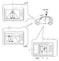
図1は本発明の実施の形態における車両用状況監視システムが取得する画像の例を示す図、図2は本発明の実施の形態における車両用状況監視システムの構成の概略を示す図である。 FIG. 1 is a diagram showing an example of an image acquired by the vehicle situation monitoring system in the embodiment of the present invention, and FIG. 2 is a diagram showing an outline of the configuration of the vehicle situation monitoring system in the embodiment of the present invention.
図1及び2において、11は本実施の形態における車両用状況監視システムの車両であり、乗用車、トラック、バス、二輪車等道路を走行可能なものであればいかなる種類のものであってもよいが、本実施の形態においては、説明の都合上、前記車両が四つの車輪を備える乗用車であるものとして説明する。 1 and 2,
また、12は車両用状況監視システムの飛行物体であり、後述される撮像装置34を搭載して空中を飛行する。前記飛行物体12は、例えば、図2に示されるようなエアジェット推進飛行物12a、小型ヘリコプタ12b、小型飛行船12c等であるが、撮像装置34を搭載して空中を飛行することができる装置であれば、いかなる装置であってもよい。なお、前記エアジェット推進飛行物12aは、空気を下方向に向けて噴出することによって浮遊力を得る装置であり、小型ヘリコプタ12bはプロペラを回転させて空気を下方向に向けて送ることによって浮遊力を得る装置であり、小型飛行船12cは水素ガス、ヘリウムガス等の空気より軽いガスが充填(てん)された風船によって浮遊力を得る装置である。なお、前記飛行物体12は、空中を前後左右上下に移動して位置を変更することができ、かつ、姿勢を変更することもできる。 Reference numeral 12 denotes a flying object of the vehicle situation monitoring system, which carries an
そして、前記車両11の運転者、同乗者等の車両用状況監視システムのユーザは、後述される飛行物体用操縦装置15を操作して前記飛行物体12の位置及び姿勢を制御し、また、後述される撮像装置用操縦装置16を操作して撮像装置34の向き及び撮像倍率を制御して、所望の画像を撮影し、図1に示されるように、後述される表示装置24に表示させることができる。 Then, a user of the vehicle situation monitoring system such as a driver or a passenger of the
図1において、13aは表示装置24に表示された撮像装置34の撮影した画像であり、車両11の前方における交通状況である渋滞の状況を示す画像である。画像13aにおける範囲Aは、前方を走行中の他の車両であるトラックのさらに前方における渋滞の状況を示している。これにより、車両11の運転者は、前方の渋滞状況を的確に把握することができ、不安や不快感を感じることがない。また、13bは表示装置24に表示された撮像装置34の撮影した画像であり、車両11の前方における交差点の状況を示す画像である。画像13bにおける範囲Bは、前方を走行中の他の車両であるトラックのさらに前方における交差点に進入してくる他車の状況を示している。これにより、車両11の運転者は、前記トラックの死角になっている前方の交差点に進入する他車の状況を的確に把握することができ、不安を感じることがない。 In FIG. 1, 13 a is an image taken by the
なお、前方を走行中の他の車両のさらに前方の画像を撮影する場合には、飛行物体12を車両の車高規制値よりも高い位置にまで上昇させることが望ましい。これにより、前方を走行中の他の車両がトラックのように車高の高いものであっても、確実に前方の画像を撮影することができる。なお、現在の車両の車高規制値は、4.1〔m〕であるので、例えば、地上から5〔m〕程度の高さに、飛行物体12を上昇させることが望ましい。 It should be noted that when taking a further forward image of another vehicle traveling ahead, it is desirable to raise the flying object 12 to a position higher than the vehicle height regulation value of the vehicle. Thereby, even if the other vehicle traveling ahead has a high vehicle height such as a truck, a forward image can be reliably captured. In addition, since the vehicle height regulation value of the current vehicle is 4.1 [m], for example, it is desirable to raise the flying object 12 to a height of about 5 [m] from the ground.
さらに、13cは表示装置24に表示された撮像装置34の撮影した画像であり、例えば、駐車する際における車両11の周囲の状況を上方から示す画像であり、車両11及びその周囲を含む範囲の画像である。画像13cにおける範囲C1は車両11自体、すなわち、自車を示し、範囲C2は車両11の死角となっている後方に存在する歩行者を示し、範囲C3は車両11の死角となっている側方に存在する歩行者を示し、範囲C4は車両11の死角となっている側方を通過する対向車を示し、範囲C5は車両11の死角となっている側方に存在する側溝を示している。これにより、車両11の運転者は、自車の死角になっている範囲に存在する歩行者、他車、障害物等の状況を的確に把握することができ、不安を感じることがない。 Furthermore, 13c is an image taken by the
なお、図2に示される例において、エアジェット推進飛行物12a、小型ヘリコプタ12b及び小型飛行船12cは線によって車両11と接続されているが、飛行物体12は車両11に搭乗しているユーザが制御することができるのであれば、必ずしも線によって車両11と接続されている必要はない。すなわち、飛行物体12及び該飛行物体12が搭載する撮像装置34は、有線制御されるものであってもよいし、無線制御されるものであってもよい。また、前記撮像装置34は、車両11の上方から前方や車両11及びその周囲を含む範囲を撮影できるのであれば、必ずしも飛行物体12に搭載される必要はなく、例えば、車両11に装着され、車両の上方に向けて伸長可能な伸縮部材としての伸縮ロッド14の先端に取り付けられたものであってもよい。 In the example shown in FIG. 2, the air jet propelled
次に、車両用状況監視システムの構成について詳細に説明する。 Next, the configuration of the vehicle situation monitoring system will be described in detail.
図3は本発明の実施の形態における車両用状況監視システムの構成の詳細を示す図である。 FIG. 3 is a diagram showing details of the configuration of the vehicle situation monitoring system according to the embodiment of the present invention.
図3に示されるように、車両用状況監視システムは、車両11に搭載される部分と飛行物体12に搭載される部分とから成る。そして、車両11には、飛行物体用操縦装置15、撮像装置用操縦装置16、モードを選択する手段としてのモード選択装置17、記憶装置としてのメモリ18、車両側中央制御装置(ECU:Electronic Control Unit)21、障害物検出センサ22、車両情報取得装置23、表示装置24及び車両側送受信機25が搭載される。また、飛行物体12には、飛行物体側中央制御装置(ECU)31、飛行物体制御装置32、電源33、撮像装置34及び飛行物体側送受信機35が搭載される。 As shown in FIG. 3, the vehicle situation monitoring system includes a part mounted on the
ここで、前記飛行物体用操縦装置15は、飛行物体12を発進させたり回収したりするとともに、飛行物体12を操縦して前後上下左右に移動させて位置を制御し、また、姿勢を制御するためのコントローラであり、例えば、ジョイスティック、ハンドル、ダイヤル、タッチパネル、ボタン等を備える。また、前記撮像装置用操縦装置16は、撮像装置34の向きを上下左右に変更したり、撮像倍率を変更、すなわち、ズームイン又はズームアウトさせたりするためのコントローラであり、例えば、ジョイスティック、ハンドル、ダイヤル、タッチパネル、ボタン等を備える。なお、前記飛行物体用操縦装置15及び撮像装置用操縦装置16はリモートコントロールユニットとして機能する。 Here, the flying
さらに、前記モード選択装置17は、飛行物体用操縦装置15及び撮像装置用操縦装置16を使用することなく、飛行物体12及び撮像装置34にあらかじめ定められた所定の動作を行わせて所定の範囲の画像を撮影させるための装置であり、初期(デフォルト)設定のモードを選択するために、例えば、ジョイスティック、ダイヤル、タッチパネル、ボタン等を備える。なお、初期設定のモードには、あらかじめ設定されたモードとして、例えば、図1における画面13cのような画像を撮影させるための自車と周辺を見るモード、図1における画面13a及び画面13bのような画像を撮影させるための前方を見るモード等がある。さらに、前記モード選択装置17は、ユーザがマニュアルに初期設定の内容を決めるためのマニュアルモードを選択することができるようになっている。該マニュアルモードを選択した場合、ユーザは、飛行物体12の位置及び姿勢並びに撮像装置34の向き及び撮像倍率を制御するための初期設定の情報を入力し、所望の方向における所望の範囲の画像を撮影させることができる。 Further, the mode selection device 17 causes the flying object 12 and the
そして、前記メモリ18は、モード選択装置17に接続され、飛行物体12及び撮像装置34が初期設定のモードに該当する状態になるように制御するための情報としての設定情報を格納する。前記初期設定のモードに該当する状態とは、例えば、自車と周辺を見る状態、前方を見る状態等であり、自車と周辺を見る状態、前方を見る状態等となるように飛行物体12の位置及び姿勢並びに撮像装置34の向き及び撮像倍率を制御するための情報としての飛行設定情報が前記メモリ18に格納されている。この場合、前方を見る状態においては、飛行物体12の高さが現在の車両の車高規制値以上、例えば、地上から5〔m〕程度となるようにして、前方を走行中の他の車両がトラックのように車高の高いものであっても、確実に前方の画像を撮影することができるような飛行設定情報をメモリ18に格納することができる。そして、前記モード選択装置17は、前記メモリ18に格納されている飛行設定情報に従った制御指令を飛行物体12及び該飛行物体12に搭載された撮像装置34に送信する。 The
また、前記障害物検出センサ22は、前記飛行物体12の障害物を検出するセンサであり、例えば、CCD(Charge Coupled Device:電荷結合素子)、CMOS(Complementary Metal Oxide Semiconductor)等の撮像素子、ミリ波レーダ装置等を備え、車両11の前方に存在する看板、トンネル、立体交差におけるアンダーパス、屋内駐車場や立体駐車場の天井等のように、前記飛行物体12が飛行するための障害となるものの存在を検出する。また、車両11が車両用ナビゲーション装置を搭載している場合には、該車両用ナビゲーション装置の備える地図データを参照することもできる。この場合、車両用ナビゲーション装置の備えるGPS(Global Positioning System)センサ等を含む現在位置検出手段から車両11の現在位置を取得し、車両11が走行している道路上における進行方向前方に存在するトンネル、立体交差におけるアンダーパス等の障害物の位置を検出することができる。これにより、前記飛行物体12は、障害物に妨げられることなく飛行することができる。 The
さらに、前記車両情報取得装置23は、車両11の姿勢、動作等に関する情報としての車両情報を取得する装置である。そして、前記車両情報取得装置23には、運転者が操作する車両11のアクセル開閉状態を検出するアクセルセンサ、運転者が操作する車両11のブレーキペダルの動きを検出するブレーキスイッチ、運転者が操作する車両11のステアリングの舵(だ)角を検出するステアリングセンサ、車両11の方向指示器としてのウィンカの動作を検出するウィンカセンサ、車両11の変速機のシフトポジションを検出するシフトレバーセンサ、車両11の速度を検出する車速センサ、車両11の加速度を検出するGセンサ等の加速度センサ、車両11のヨーレートを検出するヨーレートセンサ、車両11の原動機のスロットル開度を検出するスロットル開度センサ等が含まれる。 Further, the vehicle
また、前記表示装置24は、CRTディスプレイ、液晶ディスプレイ、LED(Light Emitting Diode)ディスプレイ、プラズマディスプレイ、フロントガラスにホログラムを投影するホログラム装置等から成り、撮像装置34の撮影した画像を表示するとともに、飛行物体12の位置や状態、撮像装置34の向き及び撮像倍率、飛行物体12の電源33のSOC(State of Charge)等の情報も表示することができる。なお、車両11が車両用ナビゲーション装置、車両用テレビ受像器、DVD表示装置等を搭載している場合には、これら装置の表示装置を前記表示装置24として使用することもできる。 The
さらに、前記車両側中央制御装置21は、飛行物体用操縦装置15、撮像装置用操縦装置16、モード選択装置17、障害物検出センサ22、車両情報取得装置23、表示装置24及び車両側送受信機25と接続され、車両用状況監視システム全体の制御を行う装置である。そして、前記車両側中央制御装置21は、CPU、MPU等の演算手段、半導体メモリ、磁気ディスク等の記憶手段、入出力インターフェイス等を備え、プログラムに従って動作を行う一種のコンピュータである。また、前記車両側送受信機25は、飛行物体12に搭載された飛行物体側送受信機35と有線又は無線によって通信を行うための通信インターフェイスである。 Further, the vehicle-side
そして、前記飛行物体側中央制御装置31は、飛行物体制御装置32、電源33、撮像装置34及び飛行物体側送受信機35と接続され、前記車両側中央制御装置21からの指令に従って飛行物体11及び撮像装置34の動作を制御するとともに、飛行物体11及び撮像装置34の状態に関する情報、並びに、撮像装置34の撮影した画像を車両側中央制御装置21に送信する装置である。なお、前記飛行物体側中央制御装置31は、CPU、MPU等の演算手段、半導体メモリ、磁気ディスク等の記憶手段、入出力インターフェイス等を備え、プログラムに従って動作を行う一種のコンピュータである。 The flying object side
また、前記飛行物体制御装置32は、飛行物体12の動作を制御する装置であり、飛行物体12の姿勢を安定させたり、飛行物体12の位置を検出、すなわち、X座標、Y座標及びZ座標を検出したり、飛行物体12を移動させたりするための制御を行う。この場合、前記飛行物体制御装置32は、飛行物体側中央制御装置31を介して車両側中央制御装置21から受け取った移動指示、障害物回避指示等に従って制御を行う。また、飛行物体12の現在位置や姿勢状態に関する情報を飛行物体側中央制御装置31を介して車両側中央制御装置21に送信する。 The flying
さらに、前記撮像装置34は、CCD、CMOS等の撮像素子、レンズ、プリズム等の光学素子等を備え、指定された方向の画像を指定された倍率で撮影するための装置である。この場合、前記撮像装置34は、向きを上下左右に変更したり、撮像倍率を変更、すなわち、ズームイン又はズームアウトさせたり、画像の撮影の開始及び停止を行ったりすることができる。なお、前記撮像装置34の撮影する画像は、動画であり、カラー画像であることが望ましいが、静止画であり、モノクロ画像であってもよい。また、前記撮像装置34は、飛行物体側中央制御装置31を介して車両側中央制御装置21から受け取った向きに関する指示、ズーム指示等に従って画像の撮影を行い、向きやズームに関する情報及び撮影した画像を飛行物体側中央制御装置31を介して車両側中央制御装置21に送信する。 Further, the
そして、前記電源33は、乾電池、蓄電池、キャパシタ(コンデンサ)、太陽電池、燃料電池等から成り、飛行物体側中央制御装置31、飛行物体制御装置32、撮像装置34及び飛行物体側送受信機35に駆動用電流を供給するとともに、飛行物体12の図示されない推力装置にも駆動量電流を供給する。なお、前記電源33が蓄電池、キャパシタ等のように、充電可能なものである場合には、車両11から電流を供給することによって、前記電源33を適宜充電することができる。また、前記電源33を省略して、車両11から供給される電流を前記駆動用電流として利用することもできる。前記車両側送受信機25と飛行物体側送受信機35とが有線によって通信を行うものである場合、すなわち、飛行物体12及び撮像装置34が有線制御されるものである場合、車両11と飛行物体12とを結ぶラインとして電力ラインを含むものを使用し、該電力ラインを通して車両11から電流を供給することができる。また、前記車両側送受信機25と飛行物体側送受信機35とが無線によって通信を行うものである場合、すなわち、飛行物体12及び撮像装置34が無線制御されるものである場合、マイクロ波によって車両11から電流を供給することができる。なお、前記電源33のSOCは、飛行物体側中央制御装置31を介して車両側中央制御装置21に送信される。 The
また、前記飛行物体側送受信機35は、車両11に搭載された車両側送受信機25と有線又は無線によって通信を行うための通信インターフェイスである。ここで、前記車両側中央制御装置21からは、車両側送受信機25及び飛行物体側送受信機35を介して、飛行物体12の移動、撮像装置34の向きやズームに関する指示が飛行物体側中央制御装置31に送信される。また、飛行物体側中央制御装置31からは、車両側送受信機25及び飛行物体側送受信機35を介して、飛行物体12の位置や状態に関する情報、撮像装置34の向きやズームに関する情報及び撮影した画像、電源33のSOC等が飛行物体側送受信機35に送信される。 The flying
次に、前記構成の車両用状況監視システムの動作について説明する。 Next, the operation of the vehicle situation monitoring system having the above-described configuration will be described.
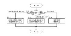
図4は本発明の実施の形態における車両用状況監視システムの動作を示すフローチャートである。 FIG. 4 is a flowchart showing the operation of the vehicle situation monitoring system according to the embodiment of the present invention.
まず、車両用状況監視システムは、飛行物体12を飛ばして画像を見るか否か、すなわち、ユーザが飛行物体12が搭載する撮像装置34によって画像を撮影することを選択したか否かを判断する(ステップS1)。そして、画像を見ない場合にはそのまま処理を終了する。また、画像を見る場合には、ユーザがモード選択装置17を操作することによって、初期設定が行われる(ステップS2)。この場合、ユーザが選択したモードに基づいて、初期設定が行われる。続いて、飛行物体12による飛行が行われる(ステップS3)。この場合、飛行物体12は初期設定に従って飛行する。そして、飛行物体12に搭載された撮像装置34によって撮影が行われる(ステップS4)。これにより、車両11の前方又は車両11の周囲の画像が撮影される。 First, the vehicle situation monitoring system determines whether or not to fly the flying object 12 and view an image, that is, whether or not the user has selected to capture an image with the
続いて、撮像装置34によって撮影された画像が表示装置24の画面に表示される(ステップS5)。これにより、ユーザは車両11の前方又は車両11の周囲の状況を的確に把握することができる。続いて、飛行設定情報変更の指示があるか否かが判断される(ステップS6)。この場合、ユーザがモード選択装置17を操作することによって飛行設定情報を変更することを指示したか否かが判断される。なお、飛行設定情報は、飛行物体12の位置及び姿勢並びに撮像装置34の向き及び撮像倍率を制御するための情報であり、飛行物体12及び撮像装置34は設定された飛行設定情報に従って動作を行う。そして、飛行設定情報変更の指示がある場合、飛行設定情報の再設定が行われる(ステップS7)。飛行設定情報の再設定は、ユーザがモード選択装置17を操作することによって他のモードを選択することによって行われる。そして、ステップS3に戻り、再び飛行が行われる。この場合、飛行物体12は再設定された飛行設定情報に従って飛行する。 Subsequently, an image photographed by the
また、飛行設定情報変更の指示がない場合、撮影が終了したか否かが判断される(ステップS8)。そして、撮影が終了していない場合には、ステップS3に戻り、再び飛行が行われる。また、撮影が終了された場合には、飛行物体12の回収が行われ(ステップS9)、処理が終了される。回収された飛行物体12は車両11内に収納される。 If there is no instruction to change the flight setting information, it is determined whether or not shooting has been completed (step S8). If shooting has not been completed, the process returns to step S3 and the flight is performed again. In addition, when shooting is finished, the flying object 12 is collected (step S9), and the process is finished. The collected flying object 12 is stored in the
次に、ステップS2のサブルーチンについて説明する。 Next, the subroutine of step S2 will be described.
図5は本発明の実施の形態における車両用状況監視システムの初期設定のサブルーチンを示すフローチャートである。 FIG. 5 is a flowchart showing an initial setting subroutine of the vehicle situation monitoring system according to the embodiment of the present invention.
初期設定においては、ユーザがモード選択装置17を操作することによって、初期設定のモードとしての画像取得モードの選択が行われる(ステップS2−1)。なお、初期設定モードの数及びその内容は任意に設定することができるが、ここでは、自車と周辺を見るモード、前方を見るモード及びマニュアルモードの3つが選択可能であるものとして説明する。 In the initial setting, the user operates the mode selection device 17 to select an image acquisition mode as an initial setting mode (step S2-1). Although the number of initial setting modes and the contents thereof can be arbitrarily set, here, description will be made assuming that three modes can be selected: a mode in which the host vehicle and the vicinity are viewed, a mode in which the vehicle is viewed in front, and a manual mode.
まず、初期設定モードとして、自車と周辺を見るモードが選択されると、モード選択装置17はメモリ18から第1の飛行設定情報の読み込みを行って(ステップS2−2)、処理を終了する。ここで、第1の飛行設定情報は、自車と周辺を見る状態となるように飛行物体12の位置及び姿勢並びに撮像装置34の向き及び撮像倍率を制御するための情報であり、あらかじめ入力されてメモリ18に格納されている。 First, when the mode for viewing the host vehicle and its surroundings is selected as the initial setting mode, the mode selection device 17 reads the first flight setting information from the memory 18 (step S2-2) and ends the processing. . Here, the first flight setting information is information for controlling the position and orientation of the flying object 12 and the direction and imaging magnification of the
また、初期設定モードとして、前方を見るモードが選択されると、モード選択装置17はメモリ18から第2の飛行設定情報の読み込みを行って(ステップS2−3)、処理を終了する。ここで、第2の飛行設定情報は、自車の前方を見る状態となるように飛行物体12の位置及び姿勢並びに撮像装置34の向き及び撮像倍率を制御するための情報であり、あらかじめ入力されてメモリ18に格納されている。 Further, when the forward viewing mode is selected as the initial setting mode, the mode selection device 17 reads the second flight setting information from the memory 18 (step S2-3) and ends the process. Here, the second flight setting information is information for controlling the position and orientation of the flying object 12, the orientation of the
さらに、初期設定モードとして、マニュアルモードが選択されると、ユーザが飛行設定情報の入力を行って(ステップS2−4)、処理を終了する。この場合、ユーザは、飛行物体12の位置及び姿勢並びに撮像装置34の向き及び撮像倍率を制御するための初期設定の情報を入力し、所望の方向における所望の範囲の画像を撮影させることができる。 Further, when the manual mode is selected as the initial setting mode, the user inputs flight setting information (step S2-4), and the process ends. In this case, the user can input information on initial settings for controlling the position and orientation of the flying object 12, the orientation of the
次に、ステップS3のサブルーチンについて説明する。 Next, the subroutine of step S3 will be described.
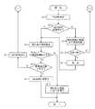
図6は本発明の実施の形態における車両用状況監視システムの飛行のサブルーチンを示すフローチャートである。 FIG. 6 is a flowchart showing a flight subroutine of the vehicle situation monitoring system according to the embodiment of the present invention.
まず、障害物の検出が行われ(ステップS3−1)、障害物検出センサ22によって検出された看板、トンネル等のような飛行物体12の障害物についての情報、すなわち、障害物検出情報が取得される。続いて、飛行物体12が発進済みであるか否かが判断され(ステップS3−2)、発進済みである場合には、飛行設定情報の検出が行われ(ステップS3−3)、初期設定において選択されたモードに対応する飛行設定情報、すなわち、現在の飛行設定情報が取得される。そして、取得された障害物検出情報及び飛行設定情報に基づいて、飛行物体12が障害物に接触するか否かが判断される(ステップS3−4)。ここで、飛行物体12が障害物に接触しない場合、飛行物体12は飛行設定情報に基づいて飛行し(ステップS3−5)、処理が終了される。 First, an obstacle is detected (step S3-1), and information about the obstacle of the flying object 12 such as a signboard or a tunnel detected by the
一方、飛行物体12が障害物に接触する場合、障害物を回避することができるか否かが判断される(ステップS3−6)。そして、障害物を回避することができる場合、飛行物体12は障害物を回避するように飛行し(ステップS3−7)、処理が終了される。この場合、飛行物体12の新たな位置、すなわち、新たなX座標、Y座標及びZ座標が指示される。また、障害物を回避することができない場合には、飛行物体12の回収が行われる(ステップS3−8)。この場合、例えば、飛行物体12及び撮像装置34が有線制御されるものであるときには、車両11と飛行物体12とを結ぶラインが回収され、また、X座標、Y座標及びZ座標が各々0となるように指示される。そして、図4に示されるフローチャートの(1)へ進み、車両用状況監視システムの処理が終了される。 On the other hand, when the flying object 12 contacts the obstacle, it is determined whether or not the obstacle can be avoided (step S3-6). If the obstacle can be avoided, the flying object 12 flies so as to avoid the obstacle (step S3-7), and the process is terminated. In this case, a new position of the flying object 12, that is, a new X coordinate, Y coordinate, and Z coordinate are designated. If the obstacle cannot be avoided, the flying object 12 is collected (step S3-8). In this case, for example, when the flying object 12 and the
また、飛行物体12が発進済みであるか否かが判断されて発進済みでない場合、取得された障害物検出情報により発進処理が行われる(ステップS3−9)。該発進処理は、障害物検出情報に基づいて、飛行物体12を飛行させるだけのスペースがあるか否かを判断するための処理である。そして、飛行物体12の発進が可能であるか否かが判断される(ステップS3−10)。ここで、発進が可能である場合、飛行物体12が発進し(ステップS3−11)、飛行設定情報に基づいて飛行する。そして、ステップS3−3に進み、飛行設定情報の検出が行われる。また、発進が可能でない場合には、図4に示されるフローチャートの(1)へ進み、車両用状況監視システムの処理が終了される。 If it is determined whether or not the flying object 12 has already started, the starting process is performed based on the acquired obstacle detection information (step S3-9). The starting process is a process for determining whether or not there is a space for flying the flying object 12 based on the obstacle detection information. Then, it is determined whether or not the flying object 12 can be started (step S3-10). Here, when it is possible to start, the flying object 12 starts (step S3-11) and flies based on the flight setting information. In step S3-3, flight setting information is detected. If the vehicle cannot be started, the process proceeds to (1) in the flowchart shown in FIG. 4 and the processing of the vehicle situation monitoring system is terminated.
このように、本実施の形態においては、リモートコントロール可能な飛行物体12に搭載された撮像装置34によって、上空から車両11の周囲及び前方の画像を撮影して表示するようになっている。そのため、駐車、狭い道路での対向車とのすれ違い、障害物の回避等の際に車両11の周囲の状況を的確に把握することができ、安全に車両11の運転を行うことができる。また、車両11の前方の路面状況、交通信号の状況、交差点の状況、交通状況等を的確に把握することができるので、運転者が不安を感じることなく、容易に、安全に車両11の運転を行うことができる。 Thus, in the present embodiment, the
なお、本発明は前記実施の形態に限定されるものではなく、本発明の趣旨に基づいて種々変形させることが可能であり、それらを本発明の範囲から排除するものではない。 In addition, this invention is not limited to the said embodiment, It can change variously based on the meaning of this invention, and does not exclude them from the scope of the present invention.
11 車両
12 飛行物体
13a、13b、13c 画像
14 伸縮ロッド
15 飛行物体用操縦装置
16 撮像装置用操縦装置
17 モード選択装置
24 表示装置
34 撮像装置DESCRIPTION OF
Claims (4)
Translated fromJapanese前記車両に搭載され、前記飛行物体及び撮像装置の動作を制御するリモートコントロールユニットと、
前記車両に搭載され、前記撮像装置が撮影した画像を表示する表示装置とを有し、
前記リモートコントロールユニットは、前記車両及びその周囲を含む範囲を前記車両の上方から撮影した画像を前記表示装置に表示させるモードを選択する手段を備えることを特徴とする車両用状況監視システム。A flying object mounted with an imaging device, launched from the vehicle and collected by the vehicle;
A remote control unit mounted on the vehicle for controlling the operation of the flying object and the imaging device;
A display device mounted on the vehicle and displaying an image captured by the imaging device;
The said remote control unit is provided with the means to select the mode which displays the image which image | photographed the range including the said vehicle and its periphery from the said vehicle on the said display apparatus, The vehicle condition monitoring system characterized by the above-mentioned.
前記車両に搭載され、前記伸縮部材及び撮像装置の動作を制御するリモートコントロールユニットと、
前記車両に搭載され、前記撮像装置が撮影した画像を表示する表示装置とを有し、
前記リモートコントロールユニットは、前記車両及びその周囲を含む範囲を前記車両の上方から撮影した画像を前記表示装置に表示させるモードを選択する手段を備えることを特徴とする車両用状況監視システム。A telescopic member that is equipped with an imaging device and that can extend toward the top of the vehicle;
A remote control unit mounted on the vehicle for controlling the operation of the telescopic member and the imaging device;
A display device mounted on the vehicle and displaying an image captured by the imaging device;
The said remote control unit is provided with the means to select the mode which displays the image which image | photographed the range including the said vehicle and its periphery from the said vehicle on the said display apparatus, The vehicle condition monitoring system characterized by the above-mentioned.
Priority Applications (1)
| Application Number | Priority Date | Filing Date | Title |
|---|---|---|---|
| JP2004372964AJP2006180326A (en) | 2004-12-24 | 2004-12-24 | Vehicle status monitoring system |
Applications Claiming Priority (1)
| Application Number | Priority Date | Filing Date | Title |
|---|---|---|---|
| JP2004372964AJP2006180326A (en) | 2004-12-24 | 2004-12-24 | Vehicle status monitoring system |
Publications (1)
| Publication Number | Publication Date |
|---|---|
| JP2006180326Atrue JP2006180326A (en) | 2006-07-06 |
Family
ID=36733984
Family Applications (1)
| Application Number | Title | Priority Date | Filing Date |
|---|---|---|---|
| JP2004372964AWithdrawnJP2006180326A (en) | 2004-12-24 | 2004-12-24 | Vehicle status monitoring system |
Country Status (1)
| Country | Link |
|---|---|
| JP (1) | JP2006180326A (en) |
Cited By (38)
| Publication number | Priority date | Publication date | Assignee | Title |
|---|---|---|---|---|
| CN105083120A (en)* | 2014-04-30 | 2015-11-25 | 比亚迪股份有限公司 | Detection system and flight apparatus for automobile surrounding environment |
| JP2016074257A (en)* | 2014-10-02 | 2016-05-12 | 株式会社フカデン | Aircraft system and composite cable used for the aircraft system |
| CN105652882A (en)* | 2015-12-29 | 2016-06-08 | 上海中科深江电动车辆有限公司 | Electric vehicle three-dimensional navigation system and electric vehicle three-dimensional navigation method based on quadcopter |
| JP2016138853A (en)* | 2015-01-29 | 2016-08-04 | 株式会社ゼンリンデータコム | Navigation system, on-vehicle navigation device, flying object, navigation method, cooperation program for on-vehicle navigation device, and cooperation program for flying object |
| JP2016138854A (en)* | 2015-01-29 | 2016-08-04 | 株式会社ゼンリンデータコム | Navigation system, navigation device, flying object, navigation cooperative control method, navigation device cooperative control program, and flying object cooperative control program |
| US9409644B2 (en) | 2014-07-16 | 2016-08-09 | Ford Global Technologies, Llc | Automotive drone deployment system |
| US9457915B2 (en) | 2014-05-30 | 2016-10-04 | SZ DJI Technology Co., Ltd | Systems and methods for UAV docking |
| JP2016194844A (en)* | 2015-04-01 | 2016-11-17 | ライトブレインラボ合同会社 | Vehicle driving support system |
| KR20160136957A (en)* | 2015-05-21 | 2016-11-30 | 경희대학교 산학협력단 | The method of ensuring visibility using drone when get on and off and the system of them |
| CN106184793A (en)* | 2016-08-29 | 2016-12-07 | 上海理工大学 | A kind of overlook image monitoring system in the air for automobile |
| DE102015007156A1 (en) | 2015-06-03 | 2016-12-08 | Audi Ag | A method in which an unmanned aerial vehicle interacts with a motor vehicle and motor vehicle |
| JP2016225983A (en)* | 2015-06-01 | 2016-12-28 | 株式会社プロドローン | Relay system |
| DE102015008768A1 (en) | 2015-07-06 | 2017-01-12 | Audi Ag | Method for assessing a motor vehicle and motor vehicle involved in an accident |
| JP2017010446A (en)* | 2015-06-25 | 2017-01-12 | 三菱自動車工業株式会社 | Driving support control device |
| JP2017021757A (en)* | 2015-07-15 | 2017-01-26 | 三菱自動車工業株式会社 | Vehicular operation support apparatus |
| JP2017504983A (en)* | 2014-04-28 | 2017-02-09 | エスゼット ディージェイアイ テクノロジー カンパニー リミテッドSz Dji Technology Co.,Ltd | platform |
| JP2017036102A (en)* | 2015-08-06 | 2017-02-16 | 株式会社豊田自動織機 | Forklift work assisting system |
| KR20170022357A (en)* | 2015-08-20 | 2017-03-02 | 한국과학기술원 | Automatic parking method and system |
| JP2017171291A (en)* | 2017-05-15 | 2017-09-28 | エスゼット ディージェイアイ テクノロジー カンパニー リミテッドSz Dji Technology Co.,Ltd | Platform and system |
| US9786105B2 (en) | 2015-12-08 | 2017-10-10 | Caterpillar Inc. | Gathering data from machine operating at worksite |
| JP2018085630A (en)* | 2016-11-24 | 2018-05-31 | 株式会社デンソー | Information providing system, device for vehicle, and information providing program |
| KR20180107131A (en)* | 2016-01-29 | 2018-10-01 | 스미토모 겐키 가부시키가이샤 | Autonomous flight vehicle flying around Chopper and Chopper |
| WO2019034365A1 (en)* | 2017-08-15 | 2019-02-21 | Zf Friedrichshafen Ag | CONTROL OF A TRANSPORT VEHICLE |
| US10558218B2 (en) | 2016-01-28 | 2020-02-11 | Fujitsu Ten Limited | Vehicle surroundings monitoring apparatus, monitoring system, remote monitoring apparatus, and monitoring method |
| WO2020116492A1 (en)* | 2018-12-05 | 2020-06-11 | 株式会社ナイルワークス | Drone system, drone, movable body, drone system control method, and drone system control program |
| CN111717407A (en)* | 2014-04-25 | 2020-09-29 | 索尼公司 | Control method and control device |
| WO2020246251A1 (en)* | 2019-06-04 | 2020-12-10 | ソニー株式会社 | Information processing device, method, and program |
| JP2021039442A (en)* | 2019-08-30 | 2021-03-11 | 楽天株式会社 | Controls, vehicles, flying objects, systems, and methods |
| US11006263B2 (en) | 2016-07-07 | 2021-05-11 | Ford Global Technologies, Llc | Vehicle-integrated drone |
| JP2021091407A (en)* | 2021-02-15 | 2021-06-17 | 京セラ株式会社 | Flight vehicle and flight vehicle control method |
| CN113050654A (en)* | 2021-03-29 | 2021-06-29 | 中车青岛四方车辆研究所有限公司 | Obstacle detection method, vehicle-mounted obstacle avoidance system and method for inspection robot |
| EP3273201B1 (en) | 2016-07-21 | 2021-06-30 | Arquus | Method of calculating an itinerary for an off-road vehicle |
| WO2021187698A1 (en)* | 2020-03-17 | 2021-09-23 | 주식회사 포드론 | Manned/unmanned aerial vehicle having device for emergency control through power regulation |
| CN113682220A (en)* | 2020-05-19 | 2021-11-23 | 马自达汽车株式会社 | Control system for vehicle-mounted flight vehicle |
| JP2021182281A (en)* | 2020-05-19 | 2021-11-25 | マツダ株式会社 | Vehicle peripheral monitoring system |
| JP2021182279A (en)* | 2020-05-19 | 2021-11-25 | マツダ株式会社 | Vehicle periphery monitoring system |
| CN113835440A (en)* | 2021-09-10 | 2021-12-24 | 广州小鹏汽车科技有限公司 | Control method and device for flight equipment, vehicle, flight equipment and storage medium |
| US11807062B2 (en) | 2019-11-25 | 2023-11-07 | Ford Global Technologies, Llc | Collaborative relationship between a vehicle and a UAV |
- 2004
- 2004-12-24JPJP2004372964Apatent/JP2006180326A/ennot_activeWithdrawn
Cited By (77)
| Publication number | Priority date | Publication date | Assignee | Title |
|---|---|---|---|---|
| CN111717407B (en)* | 2014-04-25 | 2023-09-29 | 索尼公司 | Control method and control device |
| US12140952B2 (en) | 2014-04-25 | 2024-11-12 | Sony Group Corporation | Control device, imaging device, control method, imaging method, and computer program |
| CN111717407A (en)* | 2014-04-25 | 2020-09-29 | 索尼公司 | Control method and control device |
| US10136035B2 (en) | 2014-04-28 | 2018-11-20 | SZ DJI Technology Co., Ltd. | Interchangeable mounting platform |
| US11029585B2 (en) | 2014-04-28 | 2021-06-08 | SZ DJI Technology Co., Ltd. | Interchangeable mounting platform |
| US9781313B2 (en) | 2014-04-28 | 2017-10-03 | SZ DJI Technology Co., Ltd | Interchangeable mounting assembly |
| US9777887B2 (en) | 2014-04-28 | 2017-10-03 | SZ DJI Technology Co., Ltd | Interchangeable mounting platform |
| US11927877B2 (en) | 2014-04-28 | 2024-03-12 | SZ DJI Technology Co., Ltd. | Interchangeable mounting platform |
| JP2017504983A (en)* | 2014-04-28 | 2017-02-09 | エスゼット ディージェイアイ テクノロジー カンパニー リミテッドSz Dji Technology Co.,Ltd | platform |
| US9781312B2 (en) | 2014-04-28 | 2017-10-03 | SZ DJI Technology Co., Ltd | Interchangeable mounting platform |
| US10560611B2 (en) | 2014-04-28 | 2020-02-11 | SZ DJI Technology Co., Ltd. | Interchangeable mounting platform |
| CN105083120A (en)* | 2014-04-30 | 2015-11-25 | 比亚迪股份有限公司 | Detection system and flight apparatus for automobile surrounding environment |
| JP2016535879A (en)* | 2014-05-30 | 2016-11-17 | エスゼット ディージェイアイ テクノロジー カンパニー リミテッドSz Dji Technology Co.,Ltd | System and method for UAV docking |
| US9457915B2 (en) | 2014-05-30 | 2016-10-04 | SZ DJI Technology Co., Ltd | Systems and methods for UAV docking |
| US11407526B2 (en) | 2014-05-30 | 2022-08-09 | SZ DJI Technology Co., Ltd. | Systems and methods for UAV docking |
| US12017797B2 (en) | 2014-05-30 | 2024-06-25 | SZ DJI Technology Co., Ltd. | Systems and methods for UAV docking |
| US10059467B2 (en) | 2014-05-30 | 2018-08-28 | Sz Dji Technology, Co., Ltd | Systems and methods for UAV docking |
| US10800548B2 (en) | 2014-05-30 | 2020-10-13 | SZ DJI Technology Co., Ltd. | Systems and methods for UAV docking |
| US9555885B2 (en) | 2014-07-16 | 2017-01-31 | Ford Global Technologies, Llc | Automotive drone deployment system |
| US9977431B2 (en) | 2014-07-16 | 2018-05-22 | Ford Global Technologies, Llc | Automotive drone deployment system |
| US10642279B2 (en) | 2014-07-16 | 2020-05-05 | Ford Global Technologies, Llc | Automotive drone deployment system |
| US9409644B2 (en) | 2014-07-16 | 2016-08-09 | Ford Global Technologies, Llc | Automotive drone deployment system |
| JP2016074257A (en)* | 2014-10-02 | 2016-05-12 | 株式会社フカデン | Aircraft system and composite cable used for the aircraft system |
| JP2016138854A (en)* | 2015-01-29 | 2016-08-04 | 株式会社ゼンリンデータコム | Navigation system, navigation device, flying object, navigation cooperative control method, navigation device cooperative control program, and flying object cooperative control program |
| JP2016138853A (en)* | 2015-01-29 | 2016-08-04 | 株式会社ゼンリンデータコム | Navigation system, on-vehicle navigation device, flying object, navigation method, cooperation program for on-vehicle navigation device, and cooperation program for flying object |
| JP2016194844A (en)* | 2015-04-01 | 2016-11-17 | ライトブレインラボ合同会社 | Vehicle driving support system |
| KR101715300B1 (en)* | 2015-05-21 | 2017-03-10 | 경희대학교 산학협력단 | The method of ensuring visibility using drone when get on and off and the system of them |
| KR20160136957A (en)* | 2015-05-21 | 2016-11-30 | 경희대학교 산학협력단 | The method of ensuring visibility using drone when get on and off and the system of them |
| JP2016225983A (en)* | 2015-06-01 | 2016-12-28 | 株式会社プロドローン | Relay system |
| DE102015007156B4 (en)* | 2015-06-03 | 2020-11-19 | Audi Ag | Method in which an unmanned aerial vehicle interacts with a motor vehicle, and motor vehicle |
| DE102015007156A1 (en) | 2015-06-03 | 2016-12-08 | Audi Ag | A method in which an unmanned aerial vehicle interacts with a motor vehicle and motor vehicle |
| JP2017010446A (en)* | 2015-06-25 | 2017-01-12 | 三菱自動車工業株式会社 | Driving support control device |
| DE102015008768A1 (en) | 2015-07-06 | 2017-01-12 | Audi Ag | Method for assessing a motor vehicle and motor vehicle involved in an accident |
| DE102015008768B4 (en) | 2015-07-06 | 2018-12-13 | Audi Ag | Method for assessing a motor vehicle and motor vehicle involved in an accident |
| JP2017021757A (en)* | 2015-07-15 | 2017-01-26 | 三菱自動車工業株式会社 | Vehicular operation support apparatus |
| JP2017036102A (en)* | 2015-08-06 | 2017-02-16 | 株式会社豊田自動織機 | Forklift work assisting system |
| CN106429992A (en)* | 2015-08-06 | 2017-02-22 | 株式会社丰田自动织机 | Forklift operation assist system |
| KR101720649B1 (en)* | 2015-08-20 | 2017-03-28 | 한국과학기술원 | Automatic parking method and system |
| KR20170022357A (en)* | 2015-08-20 | 2017-03-02 | 한국과학기술원 | Automatic parking method and system |
| US9786105B2 (en) | 2015-12-08 | 2017-10-10 | Caterpillar Inc. | Gathering data from machine operating at worksite |
| CN105652882A (en)* | 2015-12-29 | 2016-06-08 | 上海中科深江电动车辆有限公司 | Electric vehicle three-dimensional navigation system and electric vehicle three-dimensional navigation method based on quadcopter |
| US10558218B2 (en) | 2016-01-28 | 2020-02-11 | Fujitsu Ten Limited | Vehicle surroundings monitoring apparatus, monitoring system, remote monitoring apparatus, and monitoring method |
| JP7387684B2 (en) | 2016-01-29 | 2023-11-28 | 住友建機株式会社 | Excavators and autonomous flying vehicles |
| JPWO2017131194A1 (en)* | 2016-01-29 | 2018-11-15 | 住友建機株式会社 | Autonomous vehicle flying around a shovel and shovel |
| JP2022000570A (en)* | 2016-01-29 | 2022-01-04 | 住友建機株式会社 | Excavator and autonomous flying vehicle |
| KR20180107131A (en)* | 2016-01-29 | 2018-10-01 | 스미토모 겐키 가부시키가이샤 | Autonomous flight vehicle flying around Chopper and Chopper |
| US11492783B2 (en) | 2016-01-29 | 2022-11-08 | Sumitomo(S.H.I) Construction Machinery Co., Ltd. | Shovel and autonomous aerial vehicle flying around shovel |
| KR102615981B1 (en)* | 2016-01-29 | 2023-12-19 | 스미토모 겐키 가부시키가이샤 | Autonomous aircraft flying around shovels and shovels |
| US11006263B2 (en) | 2016-07-07 | 2021-05-11 | Ford Global Technologies, Llc | Vehicle-integrated drone |
| EP3273201B2 (en)† | 2016-07-21 | 2024-09-04 | Arquus | Method of calculating an itinerary for an off-road vehicle |
| EP3273201B1 (en) | 2016-07-21 | 2021-06-30 | Arquus | Method of calculating an itinerary for an off-road vehicle |
| CN106184793A (en)* | 2016-08-29 | 2016-12-07 | 上海理工大学 | A kind of overlook image monitoring system in the air for automobile |
| JP2018085630A (en)* | 2016-11-24 | 2018-05-31 | 株式会社デンソー | Information providing system, device for vehicle, and information providing program |
| WO2018096760A1 (en)* | 2016-11-24 | 2018-05-31 | 株式会社デンソー | Information provision system, onboard device, and information provision program |
| CN109997355A (en)* | 2016-11-24 | 2019-07-09 | 株式会社电装 | Information providing system, vehicle device, information provision procedure |
| JP2017171291A (en)* | 2017-05-15 | 2017-09-28 | エスゼット ディージェイアイ テクノロジー カンパニー リミテッドSz Dji Technology Co.,Ltd | Platform and system |
| US11507112B2 (en) | 2017-08-15 | 2022-11-22 | Zf Friedrichshafen Ag | Control of a transportation vehicle |
| WO2019034365A1 (en)* | 2017-08-15 | 2019-02-21 | Zf Friedrichshafen Ag | CONTROL OF A TRANSPORT VEHICLE |
| JP7008997B2 (en) | 2018-12-05 | 2022-01-25 | 株式会社ナイルワークス | Drone system, drone, mobile, drone system control method, and drone system control program |
| US11873100B2 (en) | 2018-12-05 | 2024-01-16 | Nileworks Inc. | Drone system, drone, movable body, drone system control method, and drone system control program |
| JPWO2020116492A1 (en)* | 2018-12-05 | 2021-02-15 | 株式会社ナイルワークス | Drone system, drone, mobile, drone system control method, and drone system control program |
| WO2020116492A1 (en)* | 2018-12-05 | 2020-06-11 | 株式会社ナイルワークス | Drone system, drone, movable body, drone system control method, and drone system control program |
| WO2020246251A1 (en)* | 2019-06-04 | 2020-12-10 | ソニー株式会社 | Information processing device, method, and program |
| JP2021039442A (en)* | 2019-08-30 | 2021-03-11 | 楽天株式会社 | Controls, vehicles, flying objects, systems, and methods |
| US11807062B2 (en) | 2019-11-25 | 2023-11-07 | Ford Global Technologies, Llc | Collaborative relationship between a vehicle and a UAV |
| US12330800B2 (en) | 2020-03-17 | 2025-06-17 | Fordrone Co., Ltd. | Manned/unmanned aerial vehicle having device for emergency control through power regulation |
| WO2021187698A1 (en)* | 2020-03-17 | 2021-09-23 | 주식회사 포드론 | Manned/unmanned aerial vehicle having device for emergency control through power regulation |
| JP7476661B2 (en) | 2020-05-19 | 2024-05-01 | マツダ株式会社 | Vehicle Surroundings Monitoring System |
| CN113682220B (en)* | 2020-05-19 | 2024-02-13 | 马自达汽车株式会社 | Control system for vehicle-mounted flying body |
| CN113682220A (en)* | 2020-05-19 | 2021-11-23 | 马自达汽车株式会社 | Control system for vehicle-mounted flight vehicle |
| JP2021182281A (en)* | 2020-05-19 | 2021-11-25 | マツダ株式会社 | Vehicle peripheral monitoring system |
| JP2021182279A (en)* | 2020-05-19 | 2021-11-25 | マツダ株式会社 | Vehicle periphery monitoring system |
| JP7589449B2 (en) | 2020-05-19 | 2024-11-26 | マツダ株式会社 | Vehicle Surroundings Monitoring System |
| JP2021091407A (en)* | 2021-02-15 | 2021-06-17 | 京セラ株式会社 | Flight vehicle and flight vehicle control method |
| JP7055909B2 (en) | 2021-02-15 | 2022-04-18 | 京セラ株式会社 | The flying object and the control method of the flying object |
| CN113050654A (en)* | 2021-03-29 | 2021-06-29 | 中车青岛四方车辆研究所有限公司 | Obstacle detection method, vehicle-mounted obstacle avoidance system and method for inspection robot |
| CN113835440A (en)* | 2021-09-10 | 2021-12-24 | 广州小鹏汽车科技有限公司 | Control method and device for flight equipment, vehicle, flight equipment and storage medium |
Similar Documents
| Publication | Publication Date | Title |
|---|---|---|
| JP2006180326A (en) | Vehicle status monitoring system | |
| CN109760676B (en) | Display system, display method, and storage medium | |
| EP3409525B1 (en) | User interface apparatus for vehicle and vehicle | |
| US11077862B2 (en) | Vehicle control system, vehicle control method, and storage medium | |
| CA3069114C (en) | Parking assistance method and parking assistance device | |
| US11180135B2 (en) | Autonomous parking system and vehicle | |
| JP6547155B2 (en) | Vehicle control system, vehicle control method, and program | |
| CN109383404B (en) | Display system, display method, and medium storing program | |
| CN110271552A (en) | Display system, display methods and storage medium | |
| WO2018087828A1 (en) | Vehicle control device, vehicle control system, vehicle control method, and vehicle control program | |
| EP3441725B1 (en) | Electronic device for vehicle and associated method | |
| CN114902018A (en) | Context sensitive user interface for enhanced vehicle operation | |
| JP7317967B2 (en) | User support method for remote control of automobile, computer program product, remote control device and driving support system for automobile | |
| CN107428249A (en) | Vehicle image display system and method | |
| US11669104B2 (en) | User-adjustable trajectories for automated vehicle reversing | |
| JP2016185745A (en) | Vehicle control device | |
| JP6508845B2 (en) | Vehicle control system, vehicle control method, and program | |
| CN107428252B (en) | Method for operating a communication device of a motor vehicle during an autonomous driving mode, communication device and motor vehicle | |
| JP7220734B2 (en) | image display system | |
| JP5067169B2 (en) | Vehicle parking assistance apparatus and image display method | |
| JP7224998B2 (en) | Information processing method, information processing device, and information processing system | |
| JP2011182059A (en) | Vehicle periphery monitoring device | |
| JP2010260483A (en) | Vehicle driving support device | |
| JP2021172311A (en) | Parking support device and parking support method | |
| JP7678407B2 (en) | Remote Parking Device |
Legal Events
| Date | Code | Title | Description |
|---|---|---|---|
| A300 | Application deemed to be withdrawn because no request for examination was validly filed | Free format text:JAPANESE INTERMEDIATE CODE: A300 Effective date:20080304 |