JP2006178811A - Storage system and storage system path control method - Google Patents
Storage system and storage system path control methodDownload PDFInfo
- Publication number
- JP2006178811A JP2006178811AJP2004372713AJP2004372713AJP2006178811AJP 2006178811 AJP2006178811 AJP 2006178811AJP 2004372713 AJP2004372713 AJP 2004372713AJP 2004372713 AJP2004372713 AJP 2004372713AJP 2006178811 AJP2006178811 AJP 2006178811A
- Authority
- JP
- Japan
- Prior art keywords
- storage device
- path
- storage
- volume
- information
- Prior art date
- Legal status (The legal status is an assumption and is not a legal conclusion. Google has not performed a legal analysis and makes no representation as to the accuracy of the status listed.)
- Pending
Links
Images


Classifications
- G—PHYSICS
- G06—COMPUTING OR CALCULATING; COUNTING
- G06F—ELECTRIC DIGITAL DATA PROCESSING
- G06F3/00—Input arrangements for transferring data to be processed into a form capable of being handled by the computer; Output arrangements for transferring data from processing unit to output unit, e.g. interface arrangements
- G06F3/06—Digital input from, or digital output to, record carriers, e.g. RAID, emulated record carriers or networked record carriers
- G06F3/0601—Interfaces specially adapted for storage systems
- G06F3/0628—Interfaces specially adapted for storage systems making use of a particular technique
- G06F3/0629—Configuration or reconfiguration of storage systems
- G06F3/0635—Configuration or reconfiguration of storage systems by changing the path, e.g. traffic rerouting, path reconfiguration
- G—PHYSICS
- G06—COMPUTING OR CALCULATING; COUNTING
- G06F—ELECTRIC DIGITAL DATA PROCESSING
- G06F11/00—Error detection; Error correction; Monitoring
- G06F11/07—Responding to the occurrence of a fault, e.g. fault tolerance
- G06F11/16—Error detection or correction of the data by redundancy in hardware
- G06F11/20—Error detection or correction of the data by redundancy in hardware using active fault-masking, e.g. by switching out faulty elements or by switching in spare elements
- G06F11/2002—Error detection or correction of the data by redundancy in hardware using active fault-masking, e.g. by switching out faulty elements or by switching in spare elements where interconnections or communication control functionality are redundant
- G06F11/2005—Error detection or correction of the data by redundancy in hardware using active fault-masking, e.g. by switching out faulty elements or by switching in spare elements where interconnections or communication control functionality are redundant using redundant communication controllers
- G—PHYSICS
- G06—COMPUTING OR CALCULATING; COUNTING
- G06F—ELECTRIC DIGITAL DATA PROCESSING
- G06F11/00—Error detection; Error correction; Monitoring
- G06F11/07—Responding to the occurrence of a fault, e.g. fault tolerance
- G06F11/16—Error detection or correction of the data by redundancy in hardware
- G06F11/20—Error detection or correction of the data by redundancy in hardware using active fault-masking, e.g. by switching out faulty elements or by switching in spare elements
- G06F11/2002—Error detection or correction of the data by redundancy in hardware using active fault-masking, e.g. by switching out faulty elements or by switching in spare elements where interconnections or communication control functionality are redundant
- G06F11/2007—Error detection or correction of the data by redundancy in hardware using active fault-masking, e.g. by switching out faulty elements or by switching in spare elements where interconnections or communication control functionality are redundant using redundant communication media
- G06F11/201—Error detection or correction of the data by redundancy in hardware using active fault-masking, e.g. by switching out faulty elements or by switching in spare elements where interconnections or communication control functionality are redundant using redundant communication media between storage system components
- G—PHYSICS
- G06—COMPUTING OR CALCULATING; COUNTING
- G06F—ELECTRIC DIGITAL DATA PROCESSING
- G06F3/00—Input arrangements for transferring data to be processed into a form capable of being handled by the computer; Output arrangements for transferring data from processing unit to output unit, e.g. interface arrangements
- G06F3/06—Digital input from, or digital output to, record carriers, e.g. RAID, emulated record carriers or networked record carriers
- G06F3/0601—Interfaces specially adapted for storage systems
- G06F3/0602—Interfaces specially adapted for storage systems specifically adapted to achieve a particular effect
- G06F3/0614—Improving the reliability of storage systems
- G—PHYSICS
- G06—COMPUTING OR CALCULATING; COUNTING
- G06F—ELECTRIC DIGITAL DATA PROCESSING
- G06F3/00—Input arrangements for transferring data to be processed into a form capable of being handled by the computer; Output arrangements for transferring data from processing unit to output unit, e.g. interface arrangements
- G06F3/06—Digital input from, or digital output to, record carriers, e.g. RAID, emulated record carriers or networked record carriers
- G06F3/0601—Interfaces specially adapted for storage systems
- G06F3/0668—Interfaces specially adapted for storage systems adopting a particular infrastructure
- G06F3/067—Distributed or networked storage systems, e.g. storage area networks [SAN], network attached storage [NAS]
Landscapes
- Engineering & Computer Science (AREA)
- Theoretical Computer Science (AREA)
- Physics & Mathematics (AREA)
- General Engineering & Computer Science (AREA)
- General Physics & Mathematics (AREA)
- Human Computer Interaction (AREA)
- Quality & Reliability (AREA)
- Computer Networks & Wireless Communication (AREA)
- Information Retrieval, Db Structures And Fs Structures Therefor (AREA)
- Debugging And Monitoring (AREA)
Abstract
Translated fromJapaneseDescription
Translated fromJapanese本発明は、ストレージシステム及びストレージシステムのパス制御方法に関する。 The present invention relates to a storage system and a storage system path control method.
例えば、政府、官公庁、地方自治体、企業、教育機関等では、多種多量のデータを取り扱うために、比較的大規模な記憶システムを用いてデータを管理する。この記憶システムは、例えば、ディスクアレイ装置等から構成される。ディスクアレイ装置は、多数の記憶デバイスをアレイ状に配設して構成されるもので、例えば、RAID(Redundant Array of Independent Disks)に基づく記憶領域を提供する。 For example, a government, a public office, a local government, a company, an educational institution, and the like manage data using a relatively large-scale storage system in order to handle a large amount of data. This storage system is composed of, for example, a disk array device. The disk array device is configured by arranging a large number of storage devices in an array, and provides a storage area based on, for example, RAID (Redundant Array of Independent Disks).
記憶デバイス群が提供する物理的な記憶領域上には少なくとも1つ以上の論理ボリューム(論理ユニット)が形成され、この論理ボリュームがホストコンピュータ(より詳しくは、ホストコンピュータ上で稼働するデータベースプログラム)に提供される。ホストコンピュータ(以下、「ホスト」と略記)は、所定のコマンドを送信することにより、論理ボリュームに対してデータの書込み、読み出しを行うことができる。 At least one logical volume (logical unit) is formed on the physical storage area provided by the storage device group, and this logical volume is stored in the host computer (more specifically, a database program running on the host computer). Provided. A host computer (hereinafter abbreviated as “host”) can write and read data to and from a logical volume by sending a predetermined command.
情報化社会の進展等につれて、管理すべきデータは、日々増大する。このため、より高性能、より大容量のストレージ装置が求められており、この市場要求に応えるべく、複数のストレージ装置を用いてストレージシステムを構成する場合がある。 As the information society evolves, the data to be managed increases day by day. Therefore, there is a demand for a storage device with higher performance and larger capacity, and in order to meet this market demand, a storage system may be configured using a plurality of storage devices.
複数のストレージ装置を用いてストレージシステムを構成する場合、既存の旧型ストレージ装置を、新型のストレージ装置に置き換える方法が知られている(特許文献1)。この文献に記載の従来技術では、負荷の少ない時間帯を見計らって、新設のストレージ装置が既存のストレージ装置にデータを移行させるようになっている。
前記文献に記載のものでは、単に、既存のストレージ装置を新設のストレージ装置に置き換えるだけのものである。この文献には、一方のストレージ装置が他方のストレージ装置の記憶資源を主体的に利用することにより、ストレージシステム全体の記憶資源を有効に利用する等の観点は、何ら含まれていない。 In the above-mentioned document, an existing storage device is simply replaced with a new storage device. This document does not include any viewpoints such as one storage device actively using the storage resources of the other storage device to effectively use the storage resources of the entire storage system.
前記文献に記載のように、旧型のストレージ装置から新型のストレージ装置に完全に移行する場合は、新型のストレージ装置の機能や性能を利用可能である。しかし、データ移行の完了後は、旧型のストレージ装置が無駄になり、旧型のストレージ装置を有効に利用することができない。 As described in the above document, when the old storage device is completely migrated to the new storage device, the functions and performance of the new storage device can be used. However, after the data migration is completed, the old storage device is wasted and the old storage device cannot be used effectively.
本発明は、上記の問題点に鑑みてなされたもので、本発明の一つの目的は、複数のストレージ装置を連携させて記憶資源を有効に利用でき、使い勝手または信頼性を向上できるようにしたストレージシステム及びストレージシステムのパス制御方法を提供することにある。本発明の目的の一つは、複数のストレージ装置を複数の通信パスを介して接続し、ストレージシステムの使用状況に応じて、通信パスを切り替えることができるようにしたストレージシステム及びストレージシステムのパス制御方法を提供することにある。本発明の更なる目的は、後述する実施の形態の記載から明らかになるであろう。 The present invention has been made in view of the above-described problems, and one object of the present invention is to enable efficient use of storage resources by linking a plurality of storage apparatuses, and to improve usability or reliability. To provide a storage system and a storage system path control method. One of the objects of the present invention is to connect a plurality of storage devices via a plurality of communication paths, and to switch the communication path according to the usage status of the storage system, and the path of the storage system. It is to provide a control method. Further objects of the present invention will become clear from the description of the embodiments described later.
上記課題を解決すべく、本発明に従うストレージシステムは、ホストによって使用される仮想ボリュームを有する第1ストレージ装置と、この第1ストレージ装置と複数の通信パスを介して接続され、仮想ボリュームに対応付けられる実ボリュームを有する第2ストレージ装置と、各通信パスによって仮想ボリュームと実ボリュームとをそれぞれ接続し、実ボリュームを仮想ボリュームのデータ格納先ボリュームとしてマッピングするマッピング管理部と、このマッピング管理部により管理されている仮想ボリュームと実ボリュームとのマッピング情報に基づいて、ホストから仮想ボリュームへのアクセス要求を処理する制御部と、を備えている。そして、制御部は、各通信パスのうち少なくともいずれか一つ以上の通信パスを選択して、アクセス要求を処理可能である。 In order to solve the above problems, a storage system according to the present invention is connected to a first storage device having a virtual volume used by a host, and the first storage device through a plurality of communication paths, and is associated with the virtual volume. A mapping management unit for connecting the virtual volume and the real volume by each communication path, mapping the real volume as a data storage destination volume of the virtual volume, and managing by the mapping management unit And a controller that processes an access request from the host to the virtual volume based on the mapping information between the virtual volume and the real volume. And a control part can process an access request by selecting at least any one or more of the communication paths.
ここで、第1ストレージ装置は、例えば、ディスクアレイサブシステム等のように、記憶資源を内蔵する装置として構成可能である。しかし、これに限らず、第1ストレージ装置は、例えば、インテリジェント化されたファイバチャネルスイッチ等のように構成することもできる。第1ストレージ装置は、ストレージサービスをホストに提供するための物理的な記憶資源を持たない装置として構成可能である。第1ストレージ装置は、実際にデータを格納する物理的なボリュームを有している必要はなく、仮想的なボリュームを設定可能であればよい。 Here, the first storage device can be configured as a device incorporating a storage resource, such as a disk array subsystem. However, the present invention is not limited to this, and the first storage device can also be configured as an intelligent fiber channel switch, for example. The first storage device can be configured as a device that does not have physical storage resources for providing storage services to the host. The first storage device does not need to have a physical volume that actually stores data, but only needs to be able to set a virtual volume.
仮想ボリュームと実ボリュームとは、複数の通信パスを介して接続されており、実ボリュームは、仮想ボリュームのデータ格納先ボリュームとして使用される。即ち、ホストが仮想ボリュームにライトデータを書き込む場合、このライトデータは第2ストレージ装置に転送されて、実ボリュームに書き込まれる。また、ホストが仮想ボリュームからデータを読み出す場合、このリードデータは、第2ストレージ装置の実ボリュームから読み出されて、ホストに提供される。もっとも、第1ストレージ装置は、データを一時的にまたは恒久的に記憶可能なメモリを備えることができる。このメモリ内に、ホストから要求されたリードデータが記憶されている場合、第1ストレージ装置は、第2ストレージ装置からリードデータを取得する必要は必ずしもない。 The virtual volume and the real volume are connected via a plurality of communication paths, and the real volume is used as a data storage destination volume of the virtual volume. That is, when the host writes write data to the virtual volume, this write data is transferred to the second storage device and written to the real volume. When the host reads data from the virtual volume, the read data is read from the real volume of the second storage device and provided to the host. However, the first storage device can include a memory capable of temporarily or permanently storing data. When read data requested from the host is stored in this memory, the first storage device does not necessarily need to acquire read data from the second storage device.
本発明の実施形態では、各通信パスにはそれぞれ予め優先度が設定されている。制御部は、優先度に基づいて、使用可能な各通信パスのうち少なくともいずれか一つの通信パスを選択して使用可能である。例えば、制御部は、使用可能な複数の通信パスのうち、より優先度の高い通信パスを用いて、実ボリュームにアクセスすることができる。 In the embodiment of the present invention, a priority is set in advance for each communication path. The control unit can select and use at least one of the available communication paths based on the priority. For example, the control unit can access the real volume using a communication path having a higher priority among a plurality of usable communication paths.
本発明の実施形態では、制御部は、各通信パスに障害が発生したか否かをそれぞれ検出する障害検出部をさらに備えている。障害検出部により、各通信パスのうち使用中の通信パスについて障害の発生が検出された場合は、各通信パスのうち使用可能な通信パスを少なくともいずれか一つ選択して使用する。即ち、使用中の通信パスに何らかの障害が発生した場合、制御部は、正常な複数の通信パスのうち優先度の高い通信パスを選択することができる。これに限らず、正常な各通信パスのうち、いずれか一つまたは複数の通信パスを任意に選択することもできる。これにより、使用中の通信パスに障害が発生して使用不能となった場合でも、制御部は、別の通信パスを用いて実ボリュームにアクセスすることができ、ホストからのアクセス要求の処理が中断しない。また、ホストからのアクセス要求を処理しながら、障害の回復作業を行うことができる。 In the embodiment of the present invention, the control unit further includes a failure detection unit that detects whether or not a failure has occurred in each communication path. If the failure detection unit detects the occurrence of a failure for a communication path in use among the communication paths, at least one of the communication paths that can be used is selected and used. That is, when a failure occurs in a communication path that is in use, the control unit can select a communication path with a high priority among a plurality of normal communication paths. Not limited to this, any one or a plurality of communication paths can be arbitrarily selected from the normal communication paths. As a result, even if a communication path that is in use fails and becomes unusable, the control unit can access the real volume using another communication path, and the access request from the host can be processed. Do not interrupt. In addition, it is possible to perform failure recovery work while processing an access request from the host.
本発明の実施形態では、マッピング管理部により管理されるマッピング情報には、少なくとも、仮想ボリュームを識別するための仮想ボリューム識別情報と、実ボリュームを識別するための実ボリューム識別情報と、仮想ボリュームから各通信パスをそれぞれ用いて実ボリュームにアクセスするための各パス情報と、各通信パスが使用可能状態であるか使用不能状態であるかを示す状態情報と、各通信パスの優先度を示す優先度情報とが対応付けられている。 In the embodiment of the present invention, the mapping information managed by the mapping management unit includes at least virtual volume identification information for identifying a virtual volume, real volume identification information for identifying a real volume, and a virtual volume. Each path information for accessing the real volume using each communication path, status information indicating whether each communication path is usable or unusable, and priority indicating each communication path priority The degree information is associated.
各パス情報は、第1ストレージ装置の有する複数の第1ポートをそれぞれ識別するための第1ポート情報と、第2ストレージ装置の有する複数の第2ポートをそれぞれ識別するための第2ポート情報と、各第2ポートにそれぞれ対応付けられている論理ユニット番号(LUN)とを対応付けることにより構成可能である。 Each path information includes first port information for identifying a plurality of first ports of the first storage device, and second port information for identifying a plurality of second ports of the second storage device, respectively. It can be configured by associating the logical unit number (LUN) associated with each second port.
第1ストレージ装置に接続される管理装置をさらに設けることもできる。そして、この管理装置によって、マッピング情報の全部または一部を更新可能に構成してもよい。 A management device connected to the first storage device may be further provided. The management apparatus may be configured to be able to update all or part of the mapping information.
さらに、管理装置は、マッピング情報の全部または一部を、予め設定された所定の接続点に接続されている少なくとも一つ以上の通信パス毎に、それぞれ更新可能に構成することもできる。ここで、所定の接続点とは、例えば、通信ポート等のように、通信パスに含まれるノードを挙げることができる。 Furthermore, the management apparatus can be configured to update all or part of the mapping information for each of at least one or more communication paths connected to a predetermined connection point set in advance. Here, the predetermined connection point may be a node included in the communication path, such as a communication port.
例えば、第1ポートまたは第2ポートまたは実ボリュームにそれぞれ接続されている少なくとも一つ以上の通信パス毎に、それぞれマッピング情報の全部または一部を更新可能に構成してもよい。即ち、第1ポート単位、第2ポート単位、実ボリューム単位のいずれかで、通信パスの構成を管理可能である。ここで、第1ポート単位とは、例えば、各第1ポートにそれぞれ接続されている通信パスの全部または一部を対象に、マッピング情報を更新可能であることを意味する。同様に、第2ポート単位とは、例えば、各第2ポートにそれぞれ接続されている通信パスの全部または一部を対象に、マッピング情報を更新可能であることを意味する。同様に、実ボリューム単位とは、例えば、実ボリュームにそれぞれ接続されている通信パスの全部または一部を対象に、マッピング情報を更新可能であることを意味する。なお、ある一組の実ボリュームと仮想ボリュームに着目すると、各通信パスの一端側は実ボリュームに接続され、各通信パスの他端側は仮想ボリュームに接続されている。従って、実ボリューム単位で通信パスの構成を管理可能な構成は、仮想ボリューム単位で通信パスの構成を管理可能な構成と等価である。 For example, all or part of the mapping information may be updated for each of at least one or more communication paths connected to the first port, the second port, or the real volume, respectively. That is, the configuration of the communication path can be managed in any one of the first port unit, the second port unit, and the real volume unit. Here, the first port unit means that the mapping information can be updated for all or a part of the communication paths connected to each first port, for example. Similarly, the second port unit means that, for example, the mapping information can be updated for all or part of the communication paths connected to the respective second ports. Similarly, the real volume unit means that, for example, the mapping information can be updated for all or a part of the communication paths respectively connected to the real volume. Focusing on a certain set of real volume and virtual volume, one end of each communication path is connected to the real volume, and the other end of each communication path is connected to the virtual volume. Therefore, a configuration capable of managing the communication path configuration in units of real volumes is equivalent to a configuration capable of managing the configuration of communication paths in units of virtual volumes.
このように、所定の単位で各通信パスの構成を管理可能な構成とすることにより、保守作業の作業効率を向上可能である。例えば、障害が発生した場合や計画的な部品交換作業等を行う場合に、障害や交換に関連する通信パスのみを切断(論理的な切断)させることができる。全ての通信パスが使用不能な場合等を除き、ホストからのアクセス要求の処理が中断することはない。 In this way, by making the configuration of each communication path manageable in a predetermined unit, the work efficiency of maintenance work can be improved. For example, when a failure occurs or when a planned parts replacement operation or the like is performed, only a communication path related to the failure or replacement can be disconnected (logically disconnected). Except when all communication paths are unavailable, the processing of access requests from the host is not interrupted.
管理装置は、少なくともマッピング情報に含まれる状態情報を更新可能であり、第1ストレージ装置または第2ストレージ装置のいずれかまたは両方を計画的に停止させる場合は、この計画的な停止に係わる所定の通信パスの状態を使用可能状態から使用不能状態に変更させ、計画的な停止が終了した場合は、所定の通信パスの状態を使用可能状態に再び変更させる構成としてもよい。 The management apparatus can update at least the state information included in the mapping information, and when either or both of the first storage apparatus and the second storage apparatus are systematically stopped, a predetermined process related to the planned stop is performed. When the state of the communication path is changed from the usable state to the unusable state and the planned stop is completed, the state of the predetermined communication path may be changed again to the usable state.
そして、制御部は、各通信パスに障害が発生したか否かをそれぞれ検出する障害検出部をさらに備えており、各通信パスのいずれかにおいて障害の発生が検出された場合、この障害の発生した通信パスの状態が使用不能状態に設定されている場合は、障害の発生を無視するように構成してもよい。これにより、例えば、第2ストレージ装置の保守作業を行う際に、保守作業に係る各通信パスの状態をそれぞれ予め使用不能状態に設定しておくことにより、検出された障害を無視することができる。従って、第2ストレージ装置の計画的な保守作業によって、障害発生が検出されてしまい、外部の保守管理センタ等に通知される事態を未然に防止することができる。 The control unit further includes a failure detection unit that detects whether or not a failure has occurred in each communication path. If a failure is detected in any of the communication paths, the occurrence of this failure is detected. If the state of the communication path is set to the unusable state, the occurrence of a failure may be ignored. Accordingly, for example, when performing maintenance work on the second storage device, the detected failure can be ignored by setting the state of each communication path related to the maintenance work to an unusable state in advance. . Accordingly, it is possible to prevent a situation in which the occurrence of a failure is detected by a planned maintenance operation of the second storage device and notified to an external maintenance management center or the like.
管理装置が所定の通信パスの状態を使用不能状態に変更した場合でも、優先度は固定しておくことができる。 Even when the management device changes the state of a predetermined communication path to an unusable state, the priority can be fixed.
本発明の実施形態では、制御部は、各通信パスを順番に切替ながら、アクセス要求を処理することもできる。即ち、制御部は、アクセス要求毎にそれぞれ異なる通信パスを用いて、実ボリュームにアクセスすることができる。これにより、一つの通信パスを用いてアクセス要求を処理する場合よりも、高速に処理を行うことができる。 In the embodiment of the present invention, the control unit can process the access request while sequentially switching the communication paths. In other words, the control unit can access the real volume using a different communication path for each access request. As a result, processing can be performed at a higher speed than when an access request is processed using a single communication path.
制御部は、各通信パスのうちいずれか一つの通信パスを使用してアクセス要求を処理する第1モードと、各通信パスを順番に切替ながらアクセス要求を処理する第2モードとを備えることもできる。 The control unit may include a first mode in which an access request is processed using any one of the communication paths, and a second mode in which the access request is processed while sequentially switching the communication paths. it can.
第1ストレージ装置と複数の他の通信パスを介して接続され、第1ストレージ装置が有する他の仮想ボリュームに対応付けられる他の実ボリュームを有する第3ストレージ装置を備えている場合、制御部は、ストレージ装置単位で、第1モードまたは第2モードをそれぞれ適用することもできる。即ち、例えば、制御部は、第2ストレージ装置の実ボリュームとの間では第1モードでアクセスし、第3ストレージ装置の他の実ボリュームとの間では第2モードでアクセスすることもできる。従って、例えば、高速処理が要求される仮想ボリュームには第2モードを用いる等のように、仮想ボリュームの使用態様等に応じて、アクセスモードを変えることができる。 In the case where the control unit includes the third storage device that is connected to the first storage device via a plurality of other communication paths and has another real volume that is associated with the other virtual volume of the first storage device. The first mode or the second mode can also be applied in units of storage devices. That is, for example, the control unit can access the real volume of the second storage device in the first mode and can access the other real volume of the third storage device in the second mode. Therefore, for example, the access mode can be changed according to the usage mode of the virtual volume, such as using the second mode for a virtual volume that requires high-speed processing.
本発明の別の観点に従うストレージシステムのパス制御方法は、第1ストレージ装置の有する仮想ボリュームと第2ストレージ装置の有する実ボリュームとを複数の通信パスを介してそれぞれ接続させ、仮想ボリュームと実ボリュームとの対応関係を示すマッピング情報を管理する第1ステップと、各通信パスのうちいずれか一つの通信パスを用い、マッピング情報に基づいて、ホストから仮想ボリュームへのアクセス要求を処理する第2ステップと、各通信パスに障害が発生したか否かをそれぞれ検出する第3ステップと、各通信パスのうち使用中の通信パスについて障害が発生した場合は、各通信パスのうち使用可能な通信パスを少なくともいずれか一つ選択する第4ステップと、選択された通信パスを使用してホストからのアクセス要求を処理する第5ステップと、を含む。 According to another aspect of the present invention, a storage system path control method connects a virtual volume of a first storage device and a real volume of a second storage device via a plurality of communication paths, respectively, and the virtual volume and the real volume. A first step for managing mapping information indicating the correspondence relationship between the host and a second step for processing an access request from the host to the virtual volume based on the mapping information using any one of the communication paths. And a third step for detecting whether or not a failure has occurred in each communication path, and a usable communication path in each communication path when a failure has occurred in a communication path in use in each communication path. A fourth step of selecting at least one of the access points and an access request from the host using the selected communication path. Processing the includes a fifth step.
第4ステップでは、各通信パスのうち、使用可能状態にある通信パスの中で最も優先度が高く設定されている通信パスを一つ選択することもできる。 In the fourth step, it is possible to select one of the communication paths that has the highest priority among the communication paths that are available.
マッピング情報の全部または一部を、予め設定された所定の接続点に接続されている少なくとも一つ以上の通信パス毎にそれぞれ更新可能な第6ステップをさらに備えることもできる。 It is also possible to further include a sixth step in which all or part of the mapping information can be updated for each of at least one communication path connected to a predetermined connection point set in advance.
本発明の手段、機能、ステップの全部または一部は、コンピュータシステムにより実行されるコンピュータプログラムとして構成可能な場合がある。本発明の構成の全部または一部がコンピュータプログラムから構成された場合、このコンピュータプログラムは、例えば、各種記憶媒体に固定して配布等することができ、あるいは、通信ネットワークを介して送信することもできる。 All or part of the means, functions, and steps of the present invention may be configured as a computer program executed by a computer system. When all or part of the configuration of the present invention is configured by a computer program, the computer program can be distributed and fixed to various storage media, for example, or can be transmitted via a communication network. it can.
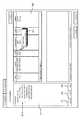
図1は、本発明の実施形態の全体概要を示す構成説明図である。本実施形態では、後述のように、外部に存在する記憶デバイスを自己の仮想的な中間記憶デバイスにマッピングすることにより、外部の記憶デバイスをあたかも自己の内部ボリュームであるかのようにして取り込み、ホストに提供する。 FIG. 1 is an explanatory diagram showing the overall outline of an embodiment of the present invention. In this embodiment, as will be described later, by mapping an external storage device to its own virtual intermediate storage device, the external storage device is captured as if it were its own internal volume, Provide to the host.
本実施形態のストレージシステムは、例えば、第1ストレージ装置1と、第2ストレージ装置2と、スイッチ3と、ホスト4と、管理装置としての管理端末5とを備えて構成することができる。 The storage system of this embodiment can be configured, for example, by including a
第1ストレージ装置1は、例えば、ディスクアレイ装置として構成される。第1ストレージ装置1は、複数の通信ポート(以下「ポート」)P0,EP1〜EP3を備えている。ポートP0は、ホスト4との通信に使用される。各ポートEP1〜EP3は、それぞれ第2ストレージ装置2との通信に使用される外部接続用ポートである。これら各ポートP0,EP1〜EP3は、仮想ボリューム1Aにそれぞれ接続されている。 The
ストレージシステムは、例えば、SAN(Storage Area Network)等のように、ファイバチャネルプロトコルに基づいてデータ通信を行うストレージシステムとして構成することができる。管理端末5と第1ストレージ装置1とは、例えば、LAN(Local Area Network)やWAN(Wide Area Netwrok)等のように、TCP/IP(Transmission Control Protocol/Internet Protocol)に基づいてデータ通信を行うネットワークで接続してもよい。以上は例示であって、本発明はプロトコルの種類に限定されるものではない。 The storage system can be configured as a storage system that performs data communication based on a fiber channel protocol, such as a SAN (Storage Area Network). The
第1ストレージ装置1は、仮想ボリューム1Aと、制御部1Bとを備えて構成することができる。仮想ボリューム1Aは、仮想的な存在であり、データを記憶する実体は、第2ストレージ装置2内に存在する。 The
即ち、第1ストレージ装置1が有する記憶階層の所定の層に、第2ストレージ装置2の有する実ボリューム2Aがマッピングされることにより、仮想ボリューム1Aが構築されている。この仮想ボリューム1Aは、各外部接続用ポートEP1〜EP3をそれぞれ介して、第2ストレージ装置2の実ボリューム2Aに接続されている。また、仮想ボリューム1Aは、ポートP0を介して、ホスト4に接続されている。 That is, the
制御部1Bは、第1ストレージ装置1の全体動作を制御するためのものである。制御部1Bは、マッピング情報1Cを保持しており、このマッピング情報1Cに基づいて、データ入出力等を制御する。 The
マッピング情報1Cには、例えば、仮想ボリューム1Aを識別するための仮想ボリューム識別情報と、実ボリューム2Aを識別するための実ボリューム識別情報と、仮想ボリューム1Aから各通信パス(以下「パス」)をそれぞれ用いて実ボリューム2Aにアクセスするための各パス情報と、各パスが使用可能状態であるか使用不能状態であるかを示す状態情報と、各パスの優先度を示す優先度情報とを含めることができる。 The
そして、マッピング情報1Cは、管理端末5からの指示によって更新可能である。即ち、管理端末5は、仮想ボリューム1Aと実ボリューム2Aとのマッピング関係を定義することができる。 The
制御部1Bは、ホスト4からポートP0を介して、仮想ボリューム1Aに対するアクセス要求を受信すると、マッピング情報1Cに基づいて、第2ストレージ装置2の実ボリューム2Aにアクセスする。 When receiving an access request for the
例えば、ライト要求の場合、制御部1Bは、ポートEP1〜EP3のうち所定のポートを介して、ホスト4から受信したライトデータを第2ストレージ装置2に転送し、実ボリューム2Aに格納させる。また、例えば、リード要求の場合、制御部1Bは、ポートEP1〜EP3のうち所定のポートを介して、第2ストレージ装置2にアクセスし、ホスト4から要求されたデータを実ボリューム2Aから読み出す。従って、ホスト4からは、仮想ボリューム1Aに直接アクセスしているかのように見える。しかし、実際のデータ格納先ボリュームは、第2ストレージ装置2の実ボリューム2Aである。 For example, in the case of a write request, the
第2ストレージ装置2は、第1ストレージ装置1と同様に、例えば、ディスクアレイ装置として構成される。第2ストレージ装置2は、複数のパスを介して、第1ストレージ装置1に接続されている。 Similar to the
第2ストレージ装置2は、例えば、実ボリューム2Aと、実ボリューム2Aにそれぞれ対応付けられた複数の外部LU2Bと、これら各外部LU2Bにそれぞれ対応付けられたポートP1〜P3とを備えることができる。なお、ここで、ホスト4へのストレージサービスは、第1ストレージ装置1によって提供されるため、第1ストレージ装置1がメインストレージとなっている。第2ストレージ装置2は、第1ストレージ装置1の外部に存在する外部ストレージである。従って、ここでは、視点を第1ストレージ装置1に置き、第2ストレージ装置2内のLUを「外部LU」と呼ぶ。 The
実ボリューム2Aは、第2ストレージ装置2内に設けられた物理的な記憶デバイスに基づいて設けられるものである。実ボリューム2Aは、上述のように、第1ストレージ装置1の仮想ボリューム1Aにマッピングされており、仮想ボリューム1Aに論理ボリュームとしての実体を提供している。 The
実ボリューム2Aには、第1ストレージ装置1と第2ストレージ装置2との間に設けられた各パスがそれぞれ接続されている。即ち、各ポートP1〜P3のいずれを介しても、実ボリューム2Aにアクセス可能である。 Each path provided between the
スイッチ3は、第1ストレージ装置1と第2ストレージ装置2との間を接続する中継装置である。スイッチ3は、例えば、ファブリック型スイッチとして構成できる。スイッチ3は、複数の一側ポート及び他側ポートを備えている。各一側ポートと各他側ポートとは、自在に接続可能である。従って、図示の例では、スイッチ3により、9通りの経路を形成することができる。 The
ここでは、発明の理解のために、3つのパスを設定するものとする。第1のパスは、第1ストレージ装置1のポートEP1と第2ストレージ装置2のポートP1とを直線的に結ぶパスである。このパスは、太線で図1中に示されている。第2のパスは、ポートEP2とポートP2とを直線的に結ぶパスであり、点線で示されている。第3のパスは、ポートEP3とポートP3とを直線的に結ぶパスである。いずれのパスも、その一端側は仮想ボリューム1Aにそれぞれ接続されており、その他端側は実ボリューム2Aに接続されている。制御部1Bは、どのパスを用いても、実ボリューム2Aにアクセスすることができる。 Here, in order to understand the invention, it is assumed that three paths are set. The first path is a path that linearly connects the port EP1 of the
次に、ストレージシステムの動作概略について説明する。まず、システム管理者等のユーザは、管理端末5を介して、第1ストレージ装置1にアクセスし、マッピング情報1Cを設定する(S1)。マッピング情報1Cが生成されることにより、第1ストレージ装置1内に仮想ボリューム1Aを生成したり、この仮想ボリューム1Aに各ポートP0,EP1〜EP3をそれぞれ割当てることができる。さらに、仮想ボリューム1Aに実ボリューム2Aをマッピングすることができる。 Next, an outline of the operation of the storage system will be described. First, a user such as a system administrator accesses the
ここでは、最初、制御部1Bは、第2パス(EP2−P2)を用いて、実ボリューム2Aにアクセスするものとする(S2)。この使用中の第2パスに障害が発生した場合(S3)、制御部1Bは、この障害発生を検出する。障害としては、例えば、ポートEP2またはポートP2の故障や、ファイバケーブルの断線等を挙げることができる。 Here, first, it is assumed that the
制御部1Bは、第2パスに障害が発生したことを検出すると、第2パスから第1パス(EP1−P1)に切り替える(S4)。これにより、ホスト4からのアクセス要求は、第1パスを用いて続行される(S5)。 When detecting that a failure has occurred in the second path, the
ここでは、第1パスに設定されている優先度が、第3パス(EP3−P3)に設定されている優先度よりも高いため、第1パスが選択される。もしも、第3パスの優先度が第1パスのそれよりも高く設定されている場合は、第3パスが選択される。 Here, since the priority set for the first path is higher than the priority set for the third path (EP3-P3), the first path is selected. If the priority of the third path is set higher than that of the first path, the third path is selected.
このように、本実施形態によれば、第1ストレージ装置1が第2ストレージ装置2の有する実ボリューム2Aを自分自身の仮想ボリューム1Aとして取り込んで利用することができる。 Thus, according to this embodiment, the
そして、本実施形態によれば、第1ストレージ装置1と第2ストレージ装置2とを複数のパスでそれぞれ接続し、いずれかのパスを用いて、実ボリューム2Aにアクセスできるようにしている。従って、使用中のパスに障害が発生した場合は、他の正常なパスに切り替えることにより、ホスト4からのアクセス要求の処理を中断することなく、続行することができ、耐障害性や信頼性が向上する。パスを切り替えて稼働させている間に、故障を回復させる作業を行うことができる。 According to this embodiment, the
また、本実施形態によれば、複数のパスを利用できるため、例えば、ポートの交換等のような計画的な保守作業を行うような場合に、ストレージシステムを停止させることなく、保守作業を行うことができる。従って、使い勝手が向上する。以下、本実施形態をより詳細に説明する。 Further, according to the present embodiment, since a plurality of paths can be used, for example, when a planned maintenance operation such as port replacement is performed, the maintenance operation is performed without stopping the storage system. be able to. Therefore, usability is improved. Hereinafter, this embodiment will be described in more detail.
図2は、本実施例によるストレージシステムの要部の構成を示すブロック図である。このストレージシステムは、それぞれ後述するように、例えば、ホスト10と、管理端末20と、管理センタ30と、複数のストレージ装置100,200と、各ストレージ装置10,200を接続するスイッチ300とを含んで構成することができる。 FIG. 2 is a block diagram showing the configuration of the main part of the storage system according to this embodiment. As will be described later, this storage system includes, for example, a
ホスト10と第1ストレージ装置100とは、通信ネットワークCN1を介して接続されている。第1ストレージ装置100と第2ストレージ装置200とは、複数の通信ネットワークCN2を介してそれぞれ接続されている。 The
第1ストレージ装置100と管理端末20とは、通信ネットワークCN3を介して接続されている。また、第1ストレージ装置100と管理センタ30とは、通信ネットワークCN4を介して接続されている。 The
ホスト10は、例えば、CPU(Central Processing Unit)やメモリ等の情報処理資源を備えたコンピュータ装置であり、例えば、パーソナルコンピュータ、ワークステーション、メインフレーム等として構成される。 The
ホスト10は、通信ネットワークCN1を介して第1ストレージ装置100にアクセスするためのHBA(Host Bus Adapter)11と、例えば、データベースソフトウェア等のアプリケーションプログラム12と、を備えている。 The
通信ネットワークCN1としては、例えば、LAN(Local Area Network)、SAN(Storage Area Network)、インターネット、専用回線、公衆回線等を場合に応じて適宜用いることができる。LANを介するデータ通信は、例えば、TCP/IPプロトコルに従って行われる。ホスト10がLANを介して第1ストレージ装置100に接続される場合、ホスト10は、ファイル名を指定してファイル単位でのデータ入出力を要求する。 As the communication network CN1, for example, a LAN (Local Area Network), a SAN (Storage Area Network), the Internet, a dedicated line, a public line, or the like can be used as appropriate. Data communication via the LAN is performed, for example, according to the TCP / IP protocol. When the
ホスト10がSANを介して第1ストレージ装置100に接続される場合、ホスト10は、ファイバチャネルプロトコルに従って、複数のディスクドライブにより提供される記憶領域のデータ管理単位であるブロックを単位としてデータ入出力を要求する。通信ネットワークCN1がLANである場合、HBA11は、例えばLAN対応のネットワークカードである。通信ネットワークCN1がSANの場合、HBA11は、例えばホストバスアダプタである。 When the
なお、ホスト10がメインフレームとして構成される場合、ホスト10は、例えば、FICON(Fibre Connection:登録商標)、ESCON(Enterprise System Connection:登録商標)、ACONARC(Advanced Connection Architecture:登録商標)、FIBARC(Fibre Connection Architecture:登録商標)等の通信プロトコルに従ってデータ転送を行う。 When the
管理端末20は、ストレージシステムの構成等を管理するためのコンピュータ装置であり、例えば、システム管理者等のユーザにより操作される。管理端末20は、通信ネットワークCN3を介して、第1ストレージ装置100に接続されている。管理端末20は、例えば、通信ネットワークCN3に接続するためのLANポート21と、ストレージ管理部22とを備えて構成することができる。ストレージ管理部22は、例えば、ソフトウェアとして構成され、第1ストレージ装置100に各種の指示を与える。この指示によって、第1ストレージ装置100内の制御情報やテーブル等を書き換えることができる。また、管理端末20は。第1ストレージ装置100から各種の情報を取得し、これを端末画面に表示させることもできる。 The
管理センタ30は、通信ネットワークCN4を介して第1ストレージ装置100に接続されている。管理センタ30は、ストレージシステムの保守を管理するためのコンピュータ装置である。管理センタ30は、第1ストレージ装置100から障害発生の通知を受けると、例えば、障害発生の事実を保守要員等に連絡する。 The
第1ストレージ装置100は、例えば、ディスクアレイサブシステムとして構成されるものである。但し、これに限らず、第1ストレージ装置100を、高機能化されたインテリジェント型のファイバチャネルスイッチとして構成してもよい。 The
第1ストレージ装置100は、後述のように、第2ストレージ装置200の有する記憶資源を、自己の論理ボリューム(Logical Unit:図中では「LDEV」と表記)としてホスト10に提供する。第1ストレージ装置100は、ストレージシステムにおけるメインストレージであり、ホスト10へストレージサービスを提供する。これに対し、第2ストレージ装置200は、メインストレージである第1ストレージ装置100によって使用される外部ストレージである。 As will be described later, the
第1ストレージ装置100は、コントローラと記憶部160とに大別することができ、コントローラは、例えば、複数のチャネルアダプタ(以下、「CHA」)110と、複数のディスクアダプタ(以下、「DKA」)120と、キャッシュメモリ130と、共有メモリ140と、接続制御部150とを備えて構成することができる。後述の図4では、コントローラ101として示す。 The
各CHA110は、ホスト10との間のデータ通信を行うものである。各CHA110は、ホスト10と通信を行うためのポート111をそれぞれ複数ずつ備えている。後述のように、各ポート111は、例えば、イニシエータポート、ターゲットポート、外部接続用ポート(Externalポート)に分類することができる。イニシエータポートは、ホストとしてコマンドを発行するためのポートである。ターゲットポートは、コマンドを受信して処理するためのポートである。外部接続用ポートは、イニシエータポートの一種であって、第2ストレージ装置200との接続に使用される。 Each
各CHA110は、それぞれCPUやメモリ等を備えたマイクロコンピュータシステムとして構成されており、ホスト10から受信した各種コマンドを解釈して実行する。各CHA110には、それぞれを識別するためのネットワークアドレス(例えば、IPアドレスやWWN)が割り当てられており、各CHA110は、それぞれが個別にNAS(Network Attached Storage)として振る舞うことも可能である。複数のホスト10が存在する場合、各CHA110は、各ホスト10からの要求をそれぞれ個別に受け付けて処理する。 Each
各DKA120は、記憶部160が有するディスクドライブ161との間でデータ授受を行うものである。各DKA120は、CHA110と同様に、CPUやメモリ等を備えたマイクロコンピュータシステムとして構成される。各DKA120は、例えば、CHA110がホスト10から受信したデータや第2ストレージ装置200から読み出されたデータを、所定のディスクドライブ161の所定のアドレスに書込む。 Each
また、各DKA120は、所定のディスクドライブ161の所定のアドレスからデータを読み出し、ホスト10または第2ストレージ装置200に送信させる。ディスクドライブ161との間でデータ入出力を行う場合、各DKA120は、論理的なアドレスを物理的なアドレスに変換する。各DKA120は、ディスクドライブ161がRAIDに従って管理されている場合は、RAID構成に応じたデータアクセスを行う。例えば、各DKA120は、同一のデータを別々のディスクドライブ群(RAIDグループ)にそれぞれ書き込んだり、あるいは、パリティ計算を実行して、データ及びパリティをディスクドライブ群に書き込む。 Each
キャッシュメモリ130は、ホスト10または第2ストレージ装置200から受信したデータを記憶したり、あるいは、ディスクドライブ161から読み出されたデータを記憶するものである。後述のように、キャッシュメモリ130の記憶空間を利用して、仮想的な中間記憶デバイスが構築される。 The
共有メモリ(制御メモリとも呼ばれる)140には、第1ストレージ装置100の作動を制御するために使用される各種の制御情報や構成情報Tc等が記憶されている。この構成情報Tcには、後述するテーブルT1〜T3等が含まれる。管理端末20は、共有メモリ140内に記憶されている構成情報Tcの全部または一部を書き換えることができるようになっている。 The shared memory (also referred to as control memory) 140 stores various control information and configuration information Tc used for controlling the operation of the
なお、各ディスクドライブ161のいずれか一つまたは複数を、キャッシュ用のディスクとして使用してもよい。また、キャッシュメモリ130と共有メモリ140とは、それぞれ別々のメモリとして構成することもできるし、同一のメモリの一部の記憶領域をキャッシュ領域として使用し、他の記憶領域を制御領域として使用することもできる。 Any one or more of the disk drives 161 may be used as a cache disk. Further, the
接続制御部150は、各CHA110,各DKA120,キャッシュメモリ130及び共有メモリ140を相互に接続させるものである。接続制御部150は、例えば、高速スイッチング動作によってデータ伝送を行う超高速クロスバスイッチ等のような高速バスとして構成することができる。 The
記憶部160は、複数のディスクドライブ161を備えている。ディスクドライブ161としては、例えば、ハードディスクドライブ、フレキシブルディスクドライブ、磁気テープドライブ、半導体メモリドライブ、光ディスクドライブ等のような各種記憶デバイス及びこれらの均等物を用いることができる。また、例えば、FC(Fibre Channel)ディスクやSATA(Serial AT Attachment)ディスク等のように、異種類のディスクを記憶部160内に混在させることもできる。 The
なお、後述のように、第1ストレージ装置100は、第2ストレージ装置200の有するディスクドライブ220に基づく仮想ボリューム163Vが形成される。この仮想ボリューム163Vは、ディスクドライブ161に基づく内部ボリューム163と同様にホスト10に提供される。 As will be described later, in the
SVP(サービスプロセッサ)170は、内部の通信ネットワークCN5を介して、例えば、各CHA110とそれぞれ接続されている。SVP170は、いずれか一つまたは複数のCHA110を介して、共有メモリ140等にアクセスすることもできる。SVP170は、LANポート180を介して、管理端末20に接続されている。また、SVP170は、例えば、公衆電話回線等の通信ネットワークCN4を介して、管理センタ30にも接続されている。SVP170は、ストレージ装置100内の各種情報を収集して管理端末20に出力可能である。また、SVP170は、管理端末20からの指示に応じて、共有メモリ140に記憶された構成情報Tcを書き換え、ストレージ装置100の構成を変更させることができる。 The SVP (service processor) 170 is connected to each
第2ストレージ装置200は、例えば、コントローラ210と、複数のディスクドライブ220とを備えて構成することができる。コントローラ210は、第2ストレージ装置200の全体動作を制御するものである。第2ストレージ装置200は、複数のポート211をそれぞれ介して、第1ストレージ装置100に接続されている。第2ストレージ装置200と第1ストレージ装置100とは、複数の通信ネットワークCN2を介して接続されている。通信ネットワークCN2は、例えば、SANやLAN等から構成可能である。 For example, the
第2ストレージ装置200は、第1ストレージ装置100とほぼ同様に構成することもできるし、第1ストレージ装置100とは異なる構成を備えることもできる。第2ストレージ装置200のディスクドライブ220は、第1ストレージ装置100の内部記憶デバイスとして扱われるようになっている。 The
スイッチ300は、第1ストレージ装置100と第2ストレージ装置200との間に設けられている。スイッチ200は、例えば、ファイバチャネルスイッチとして構成することができる。スイッチ200は、複数のポートを備えており、各ポートの接続を自在に切替可能となっている。スイッチ200の一方のポート群は、第1ストレージ装置100の有する複数の外部接続用ポートにそれぞれ接続されている。スイッチ200の他方のポート群は、第2ストレージ装置200の有する複数のターゲットポート211にそれぞれ接続されている。第1ストレージ装置100と第2ストレージ装置200とは、例えば、最大8個のパスを用いて、接続することができる。 The
図3を参照する。図3は、第1ストレージ装置100及び第2ストレージ装置200の論理的な記憶構造に着目した構成説明図である。まず、第1ストレージ装置100の構成から先に説明する。 Please refer to FIG. FIG. 3 is a configuration explanatory diagram focusing on the logical storage structures of the
第1ストレージ装置100の記憶構造は、例えば、物理的記憶階層と論理的記憶階層とに大別することができる。物理的記憶階層は、物理的なディスクであるPDEV(Physical Device)161により構成される。PDEVは、ディスクドライブに該当する。 The storage structure of the
論理的記憶階層は、複数の(例えば2種類の)階層から構成することができる。一つの論理的階層は、VDEV(Virtual Device)162と、VDEV162のように扱われる仮想的なVDEV(以下、「V−VOL」とも呼ぶ)162Vとから構成可能である。他の一つの論理的階層は、LDEV(Logical Device)163から構成することができる。 The logical storage hierarchy can be composed of a plurality of (for example, two types) hierarchies. One logical hierarchy can be composed of a VDEV (Virtual Device) 162 and a virtual VDEV (hereinafter also referred to as “V-VOL”) 162V treated like the
VDEV162は、例えば、4個1組(3D+1P)、8個1組(7D+1P)等のような所定数のPDEV161をグループ化して構成される。グループに属する各PDEV161がそれぞれ提供する記憶領域が集合して、一つのRAID記憶領域が形成される。このRAID記憶領域がVDEV162となる。 The
VDEV162が物理的な記憶領域上に構築されるのと対照的に、V−VOL162Vは、物理的な記憶領域を直接的には必要としない仮想的な中間記憶デバイスである。V−VOL162Vは、物理的な記憶領域に直接関係づけられるものではなく、第2ストレージ装置200のLU(Logical Unit)をマッピングするための受け皿となる。 In contrast to the
LDEV163は、VDEV162またはV−VOL162V上に、それぞれ少なくとも一つ以上設けることができる。LDEVは、論理ボリュームである。LDEV163は、例えば、VDEV162を固定長で分割することにより構成することができる。なお、図3中、V−VOL162上に設定されるLDEVには、符号「163V」を与えている。しかし、特に両者を区別する必要が無い場合等には、その由来を問わずにLDEV163と呼ぶ。 At least one
ホスト10がオープン系ホストの場合、LDEV163がLU164にマッピングされることにより、ホスト10は、LDEV163を一つの物理的なディスクとして認識する。オープン系のホストは、LUN(Logical Unit Number )や論理ブロックアドレスを指定することにより、所望のLDEV163にアクセスする。なお、メインフレーム系ホストの場合は、LDEV163を直接認識する。 When the
LU164は、SCSIの論理ユニットとして認識可能なデバイスである。各LU164は、ターゲットポート111Aを介して、ホスト10にそれぞれ接続可能である。各LU164には、少なくとも一つ以上のLDEV163をそれぞれ関連付けることができる。なお、一つのLU164に複数のLDEV163を関連付けることにより、LUサイズを仮想的に拡張することもできる。 The
CMD(Command Device)165は、ホスト10上で稼働するI/O制御プログラムとストレージ装置100のコントローラ(CHA110,DKA120等)との間で、コマンドやステータスを受け渡すために使用される専用のLUである。例えば、ホスト10は、コマンドをCMD165に書き込むことができる。ストレージ装置100のコントローラは、CMD165に書き込まれたコマンドに応じた処理を実行し、その実行結果をステータスとしてCMD165に書き込む。ホスト10は、CMD165に書き込まれたステータスを読出して確認し、次に実行すべき処理内容をCMD165に書き込む。このようにして、ホスト10は、CMD165を介して、ストレージ装置100に各種の指示を与えることができる。 A CMD (Command Device) 165 is a dedicated LU used to pass commands and status between the I / O control program running on the
なお、ホスト10から受信したコマンドを、CMD165に格納することなく、処理することもできる。また、実体のデバイス(LU)を定義せずに、CMDを仮想的なデバイスとして生成し、ホスト10からのコマンドを受け付けて処理するように構成してもよい。即ち、例えば、CHA110は、ホスト10から受信したコマンドを共有メモリ140に書き込み、この共有メモリ140に記憶されたコマンドを、CHA110又はDKA120が処理する。その処理結果は共有メモリ140に書き込まれ、CHA110からホスト10に送信される。 Note that a command received from the
さて、第1ストレージ装置100には、複数(例えば、8個程度)の外部接続用ポート(Externalポート)111Bが設けられている。これら各Externalポート111Bは、それぞれ通信ネットワークCN2を介して、第2ストレージ装置200の各ポート211に接続されている。また、各Externalポート111Bは、V−VOL162Vにもそれぞれ接続されている。V−VOL162Vは、複数のパスを介して、第2ストレージ装置200にそれぞれ接続されている。 The
第2ストレージ装置200は、例えば、複数のPDEV220と、各PDEV220の提供する記憶領域上に設定されたVDEV230と、VDEV230上に少なくとも一つ以上設定可能なLDEV240とを備えて構成することができる。各LDEV240は、LU250にそれぞれ関連付けられている。また、各LU250は、各ターゲットポート211にそれぞれ対応付けられている。 The
ここで、第2ストレージ装置200の各LU250は、共通のLDEV240にそれぞれ接続されている。また、各LU250は、各ポート211から各通信ネットワークCN2を介して、各Externalポート111Bにそれぞれ接続されている。上述のように、各Externalポート111Bは、共通のV−VOL162Vにそれぞれ接続されている。 Here, each
従って、第2ストレージ装置200のLDEV240は、複数のパスを介して、V-VOL162Vにそれぞれ対応付けられている。これにより、第2ストレージ装置200内のLDEV240は、第1ストレージ装置100の記憶資源として、複数のパスからそれぞれ利用可能となっている。図3中では、1組のV−VOL162V及びLDEV240を示すが、他のV−VOL162V及び他のLDEV240の組を設けることもできる。 Therefore, the
なお、VDEV162,V-VOL162Vには、RAID構成を適用することができる。即ち、1つのディスクドライブを複数のVDEV162,V-VOL162Vに割り当てることもできるし(スライシング)、複数のディスクドライブから1つのVDEV162,V-VOL162Vを形成することもできる(ストライピング)。 A RAID configuration can be applied to the
第1ストレージ装置100の「LDEV2」または「LDEV3」は、実内部ボリュームに相当し、「LDEV1」は仮想ボリュームに該当する。第2ストレージ装置200の「LDEV」は、実ボリュームに該当する。なお、第1ストレージ装置100を中心に観た場合、第2ストレージ装置200は外部ストレージとなり、第2ストレージ装置200の論理ボリューム240は外部ボリュームとなる。また、第1ストレージ装置100から観た場合、第2ストレージ装置200の各ポート211は外部ポートとなり、第1ストレージ装置100の有するポート111Bは内部ポートとなる。 “LDEV2” or “LDEV3” of the
図4を参照する。図4は、本実施例の機能構成に着目した構成説明図である。第1ストレージ装置100のコントローラ101は、各CHA110及び各DKA120と、キャッシュメモリ130及び共有メモリ140等から構成される。 Please refer to FIG. FIG. 4 is a configuration explanatory diagram focusing on the functional configuration of the present embodiment. The
このコントローラ101は、その共有メモリ140内に、後述の外部デバイス情報テーブルT1等を含む構成情報を格納している。第1ストレージ装置100には、仮想ボリューム163Vが設けられている。なお、第1ストレージ装置100は、図3中に示した内部ボリューム「LDEV2」,「LDEV3」を備えることもできるが、本発明の要旨ではないので、以下の説明では省略する。 The
V−VOL162Vに設定された仮想ボリューム163V(LDEV1)は、LU164に割り当てられて、ホスト10からのアクセスに提供される。ホスト10は、この仮想ボリューム163Vを対象として、データの書込みやデータの読み出しを指示する。 The
また、上述の通り、V−VOL162Vは、各Externalポート111Bにそれぞれ接続されており、複数のパスを介して、第2ストレージ装置200の実ボリューム240(LDEV)にそれぞれ接続されている。 As described above, the V-
第2ストレージ装置200は、実ボリューム240を備えている。実ボリューム240は、ディスクドライブ220の記憶領域に基づいて生成されたものである。実ボリューム240は、複数のパスを介して、第1ストレージ装置100のV−VOL162Vに接続されている。 The
スイッチ300は、第1ストレージ装置100と第2ストレージ装置200との間に位置し、これら各ストレージ装置100,200間を接続する。スイッチ300は、複数の一側ポート311,312,313と、複数の他側ポート321,322,323とを備えている。各一側ポート311〜313は、第1ストレージ装置100の各Externalポート111B(EP1〜EP3)にそれぞれ接続されている。各他側ポート321〜323は、第2ストレージ装置200の各ターゲットポート211(TP1〜TP3)にそれぞれ接続されている。 The
図4中では、一例として、3つのパスが示されている。第1パスは、V−VOL162Vを起点とし、ポートEP1,ポート311,ポート321,ポートTP1を順に経て、LDEV240に至る。同様に、第2パスは、V−VOL162Vを起点とし、ポートEP2,ポート312,ポート322,ポートTP2を順に経て、LDEV240に至る。同様に、第3パスは、V−VOL162Vを起点とし、ポートEP3,ポート313,ポート323,ポートTP3を順に経て、LDEV240に至る。なお、パスの数は3個に限られない。 In FIG. 4, three paths are shown as an example. The first path starts from V-
管理端末20のストレージ管理部22は、パスの構成を管理する。ストレージ管理部22は、例えば、所定のコマンドを第1ストレージ装置100に送信することにより、外部デバイス情報テーブルT1の内容を書き換えて、パスの設定や削除等を行う。 The
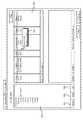
図5を参照する。図5は、第2ストレージ装置200の実ボリューム240を第1ストレージ装置100の仮想ボリューム163Vにマッピングするための外部デバイス情報テーブルT1の一例を示す。外部デバイス情報テーブルT1は、「マッピング情報」または「マッピングテーブル」の一例に該当する。 Please refer to FIG. FIG. 5 shows an example of the external device information table T1 for mapping the
外部デバイス情報テーブルT1は、例えば、V-VOL162Vを識別するための「VDEV番号」と、どのパスが有効であるかを示す「有効パスフラグ」(図中「有効パス」と略記)と、外部デバイスを識別するための情報と、外部接続パス情報テーブルとを、それぞれ対応付けることにより、構成することができる。 The external device information table T1 includes, for example, a “VDEV number” for identifying the V-
有効パスフラグは、V−VOL162Vと実ボリューム240との間に張られた各パスのうち、いずれのパスが有効であるか否かを示す情報である。フラグに「1」のセットされたパスは有効であり、「0」にリセットされたフラグは無効である。但し、そのパスが有効であっても、使用できるとは限らない。後述のように、有効なパスは、「通常状態(Normal)」と、「切断状態(Disconnect)」とのいずれかの状態を有する。切断状態のパスは、有効なパスとして存在するものの、使用することはできない。 The valid path flag is information indicating which of the paths established between the V-
外部デバイスを識別するための情報としては、例えば、シャーシ情報と、デバイス識別情報と、実ボリューム240の記憶容量と、実ボリューム240の種別を示すデバイス種別情報とを挙げることができる。 Examples of the information for identifying the external device include chassis information, device identification information, the storage capacity of the
シャーシ情報は、第2ストレージ装置200を識別するための情報であり、例えば、ベンダ名、製品名、シリアル番号等が含まれる。デバイス識別情報とは、実ボリューム240を識別するための情報である。デバイス種別情報は、例えば、テープ系デバイスであるかディスク系デバイスであるか等の種別を示す。 The chassis information is information for identifying the
以上のVDEV番号とデバイス識別情報とにより、パスの始点であるV−VOL162Vとパスの終点である実ボリューム240とをそれぞれ特定することができる。そして、外部接続パス情報には、これら各ボリューム162V,240間を結ぶ複数のパスについて、具体的な構成が示されている。 From the above VDEV number and device identification information, the V-
外部接続パス情報テーブルは、例えば、各パスに付された番号(パス番号)と、Externalポートを識別する情報(ポート番号やWWN等)と、第2ストレージ装置200のポート(外部ポート)211を識別するためのWWNと、第2ストレージ装置200のLUNを識別するためのLUN番号と、パスの状態と、パスの優先度とを、それぞれ対応付けることにより、構成することができる。 The external connection path information table includes, for example, a number (path number) assigned to each path, information for identifying an external port (port number, WWN, etc.), and a port (external port) 211 of the
パスの状態としては、例えば、通常状態(Normal)と切断状態(Disconnect)とを挙げることができる。通常状態にあるパスは、実ボリューム240へのアクセスに使用することができる。切断状態にあるパスは、論理的に切断されており、実ボリューム240へのアクセスに使用することはできない。 Examples of the path state include a normal state (Normal) and a disconnected state (Disconnect). The path in the normal state can be used for accessing the
優先度は、各パスの使用順位を示す情報である。ここでは、優先度が高くなるほど、数字が小さくなっている。各パスは、それぞれ異なる優先度を有する。優先度は、例えば、現在使用中のパスが障害等で使用不能となった場合に、代替パスを選択するための情報の一つとして使用される。 The priority is information indicating the usage order of each path. Here, the higher the priority, the smaller the number. Each path has a different priority. The priority is used as one piece of information for selecting an alternative path when, for example, the currently used path becomes unavailable due to a failure or the like.
図5に示すような外部接続パス情報テーブルを外部デバイス情報テーブルT1に内蔵させることにより、このテーブルT1を参照するだけで、コントローラ101は、実ボリューム240へアクセスするためのパスを特定することができる。なお、外部接続パス情報テーブルを外部デバイス情報テーブルT1から切り離し、両者を別々のテーブルとして構成してもよい。 By incorporating the external connection path information table as shown in FIG. 5 in the external device information table T1, the
図6を参照して、各種テーブルを利用してデータが変換される様子を説明する。図6の上部に示すように、ホスト10は、所定のターゲットポート111Aに対し、LUN番号(LUN#)及び論理ブロックアドレス(LBA)を指定してデータを送信する。 With reference to FIG. 6, how data is converted using various tables will be described. As shown in the upper part of FIG. 6, the
第1ストレージ装置100は、ホスト10から入力されたデータ(LUN#+LBA)を、図6(a)に示す変換テーブルT2に基づいて、VDEV用のデータに変換する。この変換テーブルT2は、第1ストレージ装置100内のLUNを指定するデータを、VDEV用データに変換するためのLUN−LDEV−VDEV変換テーブルである。 The
この変換テーブルT2は、例えば、LUN番号(LUN#)と、そのLUNに対応するLDEVの番号(LDEV#)及び最大スロット数と、LDEVに対応するVDEV(V-VOLを含む)の番号(VDEV#)及び最大スロット数等を対応付けることにより構成される。この変換テーブルT2を参照することにより、ホスト10からのデータ(LUN#+LBA)は、VDEV用のデータ(VDEV#+SLOT#+SUBBLOCK#)に変換される。 This conversion table T2 includes, for example, the LUN number (LUN #), the LDEV number (LDEV #) and the maximum number of slots corresponding to the LUN, and the VDEV (including V-VOL) number (VDEV) corresponding to the LDEV. #) And the maximum number of slots. By referring to this conversion table T2, the data (LUN # + LBA) from the
次に、第1ストレージ装置100は、図6(b)に示すように、外部デバイス情報テーブルT1を参照する。これにより、第1ストレージ装置100は、VDEV用のデータを、第2ストレージ装置200のLUN用に送信して記憶させるためのデータに変換する。なお、説明の便宜上、図6(b)では、図5に示す外部デバイス情報テーブルT1の構成が部分的に示されている。 Next, the
外部デバイス情報テーブルT1には、例えば、VDEVの番号(VDEV#)と、有効パスフラグと、VDEVからのデータを第2ストレージ装置200に送信するためのExternalポートの番号と、第2ストレージ装置200のポートを特定するためのWWNと、そのポートを介してアクセス可能なLUNと、パスの状態及び優先度がそれぞれ対応付けられている。 In the external device information table T1, for example, a VDEV number (VDEV #), a valid path flag, an external port number for transmitting data from the VDEV to the
この外部デバイス情報テーブルT1に基づいて、第1ストレージ装置100は、ライトデータの宛先情報を、Externalポート番号#+WWN+LUN#+LBAの形式に変換する。このように宛先情報が変更されたデータは、指定されたExternalポート111Bから通信ネットワークCN2を介して、相手方のポート211に到達する。そして、データは、LDEV240の所定の場所に格納される。 Based on this external device information table T1, the
なお、仮想ボリューム163Vにアクセス可否の属性を設定する場合は、アクセス属性管理テーブルを共有メモリ140に記憶させる。その詳細は割愛するが、アクセス属性としては、例えば、「リード/ライト可能」、「ライト抑止(リードオンリー)」、「リード/ライト不可」、「空き容量0」、「コピー先設定不可」及び「隠蔽」等を挙げることができる。 Note that when setting the access permission / prohibition attribute to the
「リード/ライト可能」とは、ボリュームへの読み書きが可能である状態を示す。「ライト抑止」とは、ボリュームへの書込みが禁止され、読出しは許可される状態を示す。「リード/ライト不可」とは、ボリュームへの読み書きが禁止される状態を示す。「空き容量0」とは、ボリューム残量の問合せに対して、実際に空き容量がある場合でも、残量0(満杯)と応答する状態を示す。「コピー先設定不可」とは、そのボリュームをコピー先ボリューム(セカンダリボリューム)に設定することができない状態を示す。「隠蔽」とは、イニシエータから認識することができない状態を示す。 “Read / write possible” indicates a state in which reading and writing to the volume is possible. “Write suppression” indicates a state in which writing to the volume is prohibited and reading is permitted. “Unreadable / writable” indicates a state in which reading / writing to the volume is prohibited. “
次に、図7及び図8に基づいて、第1ストレージ装置100と第2ストレージ装置200との間のデータ入出力について説明する。図7は、データ書込み時の処理を示す模式図である。ホスト10は、アクセス権限を有する論理ボリューム(LDEV)163Vにデータを書き込むことができる。例えば、SANの中に仮想的なSANサブネットを設定するゾーニングや、アクセス可能なLUNのリストをホスト10が保持するLUNマスキングという手法により、ホスト10を特定のLDEVに対してのみアクセスさせるように設定できる。 Next, data input / output between the
ホスト10がデータを書き込もうとするボリューム163Vが、V-VOL162Vを介して外部のボリューム240に接続されている場合は、図7に示すような流れでデータが書き込まれる。図7(a)は記憶階層を中心に示す流れ図であり、図7(b)はキャッシュメモリ130の使われ方を中心に示す流れ図である。 When the
ホスト10は、書込み対象のボリューム163Vを特定するLDEV番号と、このボリューム163Vにアクセスするためのポート111Aを特定するWWNとを明示して、ライトコマンド(Write)を発行する(S21)。第1ストレージ装置100は、ホスト10からのライトコマンドを受信すると、第2ストレージ装置200に送信するためのライトコマンドを生成し、第2ストレージ装置200に送信する(S22)。第1ストレージ装置100は、ホスト10から受信したライトコマンド中のアドレス情報等を、外部ボリューム240に合わせて変更することにより、新たなライトコマンドを生成する。 The
ホスト10は、ライトデータを第1ストレージ装置200に送信する(S23)。第1ストレージ装置100に受信されたライトデータは、ボリューム163VからV-VOL162Vを介して(S24)、第2ストレージ装置200に転送される(S26)。ここで、第1ストレージ装置100は、ホスト10からのデータをキャッシュメモリ130に格納した時点で、ホスト10に対し書込み完了の応答(Good)を返す(S25)。 The
第2ストレージ装置200は、第1ストレージ装置100からライトデータを受信した時点で(あるいはディスクドライブ220に書込みを終えた時点で)、書込み完了報告を第1ストレージ装置100に送信する(S26)。即ち、第1ストレージ装置100がホスト10に対して書込み完了を報告する時期(S25)と、実際にデータがディスクドライブ220に記憶される時期とは相違する(非同期方式)。従って、ホスト10は、実際にライトデータがディスクドライブ220に格納される前に、データ書込み処理から解放され、別の処理を行うことができる。 When the
図7(b)を参照する。キャッシュメモリ130には、多数のサブブロックが設けられている。第1ストレージ装置100は、ホスト10から指定された論理ブロックアドレスをサブブロックのアドレスに変換し、キャッシュメモリ130の所定箇所にデータを格納する(S24)。換言すれば、V-VOL162V及びVDEV162は、それぞれキャッシュメモリ130の記憶空間に設けられた論理的な存在である。 Reference is made to FIG. The
図8を参照して、第2ストレージ装置200の外部ボリューム240からデータを読み出す場合の流れを説明する。まず、ホスト10は、ポート111Aを指定して第1ストレージ装置100にデータの読み出しコマンド(Read)を送信する(S31)。第1ストレージ装置100は、リードコマンドを受信すると、要求されたデータを第2ストレージ装置200から読み出すべく、新たなリードコマンドを生成する。 With reference to FIG. 8, a flow when data is read from the
そして、第1ストレージ装置100は、生成したリードコマンドを第2ストレージ装置200に送信する(S32)。第2ストレージ装置200は、第1ストレージ装置100から受信したリードコマンドに応じて、要求されたデータをディスクドライブ220から読み出す。第2ストレージ装置200は、この読出したデータを第1ストレージ装置100に送信し(S33)、正常に読み出しが完了した旨を報告する(S35)。図8(b)に示すように、第1ストレージ装置100は、第2ストレージ装置200から受信したデータを、キャッシュメモリ130の所定の場所に格納させる(S34)。 Then, the
第1ストレージ装置100は、キャッシュメモリ130に格納されたデータを読み出し、アドレス変換を行った後、LUN164等を介してホスト10にデータを送信し(S36)、読み出し完了報告を行う(S37)。これらデータ読み出し時の一連の処理では、図6と共に述べた変換操作が逆向きで行われる。 The
図8では、ホスト10からの要求に応じて、第2ストレージ装置200からデータを読み出し、キャッシュメモリ130に保存するかのように示している。しかし、これに限らず、第2ストレージ装置200のボリューム240に記憶されているデータの全部または一部を、予めキャッシュメモリ130に記憶させておくこともできる。この場合、ホスト10からのリードコマンドに対し、直ちにキャッシュメモリ130からデータを読み出してホスト10に送信することができる。 In FIG. 8, data is read from the
図9は、第2ストレージ装置200の構成情報を取得するための処理の概要を示すフローチャートである。まず、第1ストレージ装置100は、CHA110のExternalポート111Bを介して、第2ストレージ装置200にログインする(S41)。第2ストレージ装置200が、第1ストレージ装置100のログインに対して応答を返すことにより、ログインが完了する(S42)。次に、第1ストレージ装置100は、例えば、SCSI(Small Computer System Interface)規格で定められている照会コマンド(inquiryコマンド)を、第2ストレージ装置200に送信し、第2ストレージ装置200のボリューム240について詳細な情報を求める(S43)。 FIG. 9 is a flowchart showing an overview of a process for acquiring configuration information of the
照会コマンドは、照会先の装置の種類及び構成を明らかにするために用いられるもので、照会先装置(第2ストレージ装置200)の有する階層を透過してその物理的構造を把握することができる。照会コマンドを使用することにより、第1ストレージ装置100は、例えば、装置名、デバイスタイプ、製造番号(プロダクトID)、LDEV番号、各種バージョン情報、ベンダID等の情報を第2ストレージ装置200からそれぞれ取得することができる(S44)。第2ストレージ装置200は、問合せされた情報を第1ストレージ装置100に送信し、応答する(S45)。 The inquiry command is used to clarify the type and configuration of the inquiry destination device, and can grasp the physical structure of the inquiry destination device (second storage device 200) through the hierarchy. . By using the inquiry command, the
第1ストレージ装置100は、第2ストレージ装置200から取得した情報を、外部デバイス情報テーブルT1の所定箇所に登録する(S46)。第1ストレージ装置100は、第2ストレージ装置200からボリューム240の記憶容量を読み出す(S47)。第2ストレージ装置200は、第1ストレージ装置100からの問合せに対して、ボリューム240の記憶容量を返信し(S48)、応答を返す(S49)。第1ストレージ装置100は、ボリューム240の記憶容量を外部デバイス情報テーブルT1の所定箇所に登録する(S50)。以上の処理等を行うことにより、外部デバイス情報テーブルT1を構築できる。 The
図10は、V−VOL162Vと外部ボリューム240とを結ぶパスを設定する処理の概要を示すフローチャートである。この処理は、例えば、管理端末20のストレージ管理部22によって実行することができる。 FIG. 10 is a flowchart showing an outline of processing for setting a path connecting the V-
管理端末20の端末画面には、例えば、パス設定を行うための画面が表示される。この画面を操作することにより、システム管理者等のユーザは、パスの追加を行うか、またはパスの削除を行うかを選択することができる。 On the terminal screen of the
パスの追加を行う場合(S61:YES)、ユーザは、追加しようとするパスの各パラメータをそれぞれ指定する(S62)。パラメータとしては、例えば、VDEV番号、有効パスフラグ、Externalポート番号、WWN、外部LUN番号及び優先度を挙げることができる。 When adding a path (S61: YES), the user designates each parameter of the path to be added (S62). Examples of parameters include a VDEV number, valid path flag, external port number, WWN, external LUN number, and priority.
管理端末20は、パスの追加に必要なパラメータがそれぞれ指定されると(S62)、パス追加用のコマンドを生成し、このコマンドを通信ネットワークCN3を介して第2ストレージ装置200に送信する(S63)。 When the parameters necessary for adding the path are respectively designated (S62), the
図10の下側に、パスを追加する場合のコマンド401の例を示す。パス追加用のコマンド「Set Alternate Path」の各パラメータには、ユーザによって指定された値がそれぞれ格納されている。第1ストレージ装置100は、このコマンドを受信すると、外部デバイス情報テーブルT1に新たなパスを追加する。図5に示す外部デバイス情報テーブルT1の構成と比較すると明らかなように、コマンド401には、新たなパスの構成を定義するために必要な殆どの情報が含まれている。換言すれば、コマンド401には、テーブルT1の一行分の配列がほぼ含まれている。従って、第1ストレージ装置100は、コマンド401を受信すると、このコマンド401に含まれる情報をテーブルT1に登録するだけでよく、比較的簡単にパスを追加することができる。 An example of a
一方、ユーザがパスの削除を希望する場合(S61:NO,S64:YES)、ユーザは、削除しようとするパスを選択する(S65)。管理端末20は、有効パスフラグの各ビットのうち、選択されたパスに対応するビットを0にリセットする(S66)。管理端末20は、削除用のコマンド402を生成し、このコマンド402を第1ストレージ装置100に送信する(S67)。 On the other hand, when the user wishes to delete the path (S61: NO, S64: YES), the user selects the path to be deleted (S65). The
図10の下側に示すように、パス削除用のコマンド402は、パス追加用のコマンド401と同様に構成されている。但し、パス削除用コマンド402のパラメータとしては、例えば、削除対象の有効パスフラグ及びVDEV番号のみが実質的に含まれており、他のパラメータはヌル状態となっている。例えば、第3パスを削除する場合、3番目のビットがリセットされた有効パスフラグが生成される。第1ストレージ装置100は、有効パスフラグの状態を確認し、第3パスの情報を外部デバイス情報テーブルT1から削除する。 As shown in the lower part of FIG. 10, the
図11は、外部接続パスの更新処理の概略を示すフローチャートである。この処理では、例えば、パスの切断(Disconnect)、または、切断されたパスの回復のいずれかを行うことができる。本処理も、管理端末20のストレージ管理部22により実行される。 FIG. 11 is a flowchart showing an outline of the external connection path update processing. In this process, for example, either path disconnection or recovery of a disconnected path can be performed. This process is also executed by the
ユーザは、管理端末20の端末画面に表示されたパス更新画面により、パスの切断またはパスの回復のいずれを行うか選択することができる。パスの切断を行う場合(S71:YES)、ユーザは、切断するパスのパラメータをそれぞれ指定する(S72)。パラメータとしては、例えば、VDEV番号、Externalポート番号、WWN、外部LUN番号等を挙げることができる。ここで、優先度を指定する必要はない。パスを論理的に切断する場合、優先度はそのまま維持されるためである。管理端末20は、パス切断に使用するパラメータを取得すると、パス切断用のコマンド411を生成し、これを第1ストレージ装置100に送信する(S73)。 The user can select whether to perform path disconnection or path recovery on the path update screen displayed on the terminal screen of the
パス切断用コマンド411は、例えば、パスの切断指令であることを示す情報(Disconnect)と、VDEV番号、Externalポート番号、WWN、外部LUN番号、操作結果を含んで構成することができる。操作結果の欄には、第1ストレージ装置100から返される状態が格納される。即ち、第1ストレージ装置100から返信されたコマンド411Aに示すように、パスの論理的な切断が正常に完了した場合、操作結果の欄には、「正常」を示す情報が格納される。 The
なお、切断されたパスは、第1ストレージ装置100による定期的な監視対象から外される。また、切断されたパスは、データ転送に使用することはできない。パスを切断した場合でも、そのパスの優先度は変化しないが、代替パスとして選択されることはない。従って、切断されたパスについては、I/O前の接続状態チェックも行われない。 The disconnected path is excluded from the regular monitoring targets by the
一方、ユーザがパスの回復を希望する場合(S71:NO,S74:YES)、ユーザは、回復させるパスを特定するためのパラメータをそれぞれ入力する(S75)。このパラメータは、S72で述べたものと同様である。管理端末20は、パス回復用のコマンド412を生成し、これを第1ストレージ装置100に送信する(S76)。 On the other hand, when the user wishes to recover the path (S71: NO, S74: YES), the user inputs parameters for specifying the path to be recovered (S75). This parameter is the same as that described in S72. The
パス回復用コマンド(Check Paths)は、コマンド種別を示す情報を除いて、パス切断用コマンド411と同様に構成可能である。第1ストレージ装置100がパスの回復操作に成功すると、第1ストレージ装置100から管理端末20にコマンド412Aが返信され、その操作結果の欄には、「正常」を示す情報が格納される。 The path recovery command (Check Paths) can be configured in the same manner as the
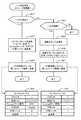
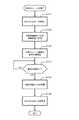
図12は、Writeコマンドの処理中に障害が発生した場合の全体動作の概略を示すシーケンスフローチャートである。 FIG. 12 is a sequence flowchart showing an outline of the entire operation when a failure occurs during the processing of the Write command.
ホスト10は、第1ストレージ装置100に向けて、仮想ボリューム163Vを書込み対象とするライトコマンドを発行し、ライトデータを送信する(S81)。第1ストレージ装置100は、ホスト10から受信したライトデータをキャッシュメモリ130に記憶させる(S82)。第1ストレージ装置100は、ライトデータをキャッシュメモリ130に記憶させた後、直ちに、ホスト10に処理完了を報告する(S83)。 The
また、第1ストレージ装置100は、外部デバイス情報テーブルT1を参照して新たなライトコマンドを生成し、各Externalポート111Bのうち特定のExternalポート111Bを介して、第2ストレージ装置200に送信する(S84)。データ通信に使用される特定のExternalポート111Bは、例えば、現在使用可能なパスのうち最も高い優先度を有するパスのポートである。 Also, the
第2ストレージ装置200は、第1ストレージ装置100からライトデータを受信すると、これをキャッシュメモリに記憶し(S85)、処理完了を応答する(S86)。第2ストレージ装置200は、適当なタイミングで、キャッシュされたライトデータを所定のディスクドライブ220に書き込み、ディステージさせる(S87)。 When the
一方、ホスト10は、第1ストレージ装置100からの処理完了通知を受信すると(S83)、新たなライトコマンド及びライトデータを第1ストレージ装置100に送信する(S88)。前記同様に、第1ストレージ装置100は、ライトデータをキャッシュメモリ130に記憶させた後(S89)、ホスト10に処理完了を報告する(S90)。 On the other hand, when receiving the processing completion notification from the first storage device 100 (S83), the
第1ストレージ装置100は、障害が発生したか否かを監視している(S91)。障害発生を検出した場合(S91:YES)、第1ストレージ装置100は、外部デバイス情報テーブルT1を参照し(S92)、現在使用中のパスの優先度の次に高い優先度を有するパスを選択する(S93)。即ち、第1ストレージ装置100は、障害の発生したパスに代えて、使用可能なパスのうち最も高い優先度を有するパスを一つ選択する。そして、第1ストレージ装置100は、前記同様に、ライトコマンドを第2ストレージ装置200に送信する(S94)。第2ストレージ装置200は、第1ストレージ装置100からのライトデータをキャッシュメモリに記憶させ(S95)、第1ストレージ装置100に処理完了を報告する(S96)。 The
なお、図12では、説明の便宜のために、S90の後で、障害発生を監視するかのように示したが、実際には、ライトコマンドの処理プロセスとは別のプロセスとして、障害検出が実行される。 For convenience of explanation, FIG. 12 shows that the occurrence of a failure is monitored after S90, but in reality, failure detection is performed as a separate process from the write command processing process. Executed.
以上詳述した通り、本実施例によれば、外部のボリューム240をV-VOL162Vにマッピングすることにより、外部のボリューム240を第1ストレージ装置100内の論理ボリューム163Vであるかのように取り扱うことができる。従って、第2ストレージ装置200の記憶資源を第1ストレージ装置100に統合して有効に利用できる。 As described above in detail, according to this embodiment, the
本実施例では、第1ストレージ装置100と第2ストレージ装置200とを複数のパスでそれぞれ接続し、現在使用中のパスに障害が発生した場合は、別のパスを用いる構成を採用する。従って、ポートの故障やファイバケーブルの断線等が生じた場合でも、代替パスに切り替えて、ホスト10からのアクセス要求を処理することができる。これにより、障害が発生した場合でも、外部のボリューム240へのアクセスパスを常に確保することができる。従って、障害発生中も、アクセス要求の処理を続行させることができ、この間に障害復旧作業を行うことができ、信頼性や耐障害性等を向上させることができる。 In this embodiment, the
本実施例では、各パスに予め優先度をそれぞれ設定し、優先度の高いパスを優先的に使用する構成としている。従って、障害が発生した場合に、速やかに代替パスを決定することができる。また、例えば、優先度はユーザが事前に指定可能なため、ストレージシステムの環境に応じて、各パスに優先度を設定することができる。 In the present embodiment, a priority is set for each path in advance, and a path with a higher priority is used preferentially. Therefore, when a failure occurs, an alternative path can be quickly determined. Further, for example, since the priority can be designated in advance by the user, the priority can be set for each path according to the environment of the storage system.
本実施例では、複数のパスを利用して外部ボリューム240へアクセス可能な構成を採用する。従って、障害が発生した場合に限らず、計画的な保守作業の場合にも、効果を奏する。即ち、CHA110やファイバケーブルを交換等する場合、この保守作業に係るパスを事前に切断状態とし、次に優先度の高いパスを選択させる。これにより、外部のストレージ装置200とのパスを確保しながら、保守作業を行うことができる。第1ストレージ装置100は、常に、第2ストレージ装置200へのアクセスに使用するパスを確保するように、優先度に基づいてパスを選択する。 In this embodiment, a configuration in which the
図13〜図15に基づいて、第2実施例を説明する。本実施例を含む以下の各実施例は、第1実施例の変形例に相当する。本実施例では、第1ストレージ装置100と第2ストレージ装置200とを複数のパスで接続し、これら各パスを順番に切替ながら、ホスト10からのアクセス要求を処理するようになっている。 A second embodiment will be described with reference to FIGS. Each of the following embodiments including this embodiment corresponds to a modification of the first embodiment. In this embodiment, the
図13は、WWN情報管理テーブルT3の一例を示す説明図である。WWN情報管理テーブルT3は、外部ストレージである第2ストレージ装置200の交替パスモード(使用モード)を管理するための情報である。 FIG. 13 is an explanatory diagram showing an example of the WWN information management table T3. The WWN information management table T3 is information for managing an alternate path mode (use mode) of the
交替パスモードとしては、例えば、シングルパスモードとマルチパスモードとを挙げることができる。シングルパスモードは、第1実施例で述べたように、複数のパスの中からいずれか一つのパスを選択して使用するモードである。マルチパスモードは、後述のように、複数のパスを順番に切替ながら使用するモードである。 Examples of the alternate path mode include a single path mode and a multipath mode. As described in the first embodiment, the single path mode is a mode in which any one of a plurality of paths is selected and used. As will be described later, the multipath mode is a mode in which a plurality of paths are used while being sequentially switched.
交替パスモードは、例えば、ストレージ装置単位に設定可能である。第2ストージ装置200をシングルパスモードで使用する場合、図13に示すように、第2ストレージ装置200の各ポート211のWWNには、シングルパスモードがそれぞれ設定される。第2ストレージ装置200をマルチパスモードで使用する場合、各ポート211を識別するためのWWNには、それぞれマルチパスモードが設定される。 The alternate path mode can be set for each storage device, for example. When the
なお、図13中では、複数のストレージ装置について、ストレージ装置単位で交替パスモードをそれぞれ設定する様子が示されている。但し、場合によっては、同一のストレージ装置内で、異なる種類の交替パスモードを混在させることも可能である。 FIG. 13 shows a state in which an alternate path mode is set for each storage device for a plurality of storage devices. However, in some cases, different types of alternate path modes can be mixed in the same storage device.
次に、図14は、マルチパスモードによるWriteコマンド処理の概略を示すフローチャートである。第1ストレージ装置100は、ホスト10からライトコマンド及びライトデータをそれぞれ受信すると(S101:YES)、ライトデータをキャッシュメモリ130に記憶させ(S102)、処理完了をホスト10に報告する(S103)。 Next, FIG. 14 is a flowchart showing an outline of Write command processing in the multi-pass mode. When the
第1ストレージ装置100は、障害が発生したか否かを監視している(S104)。障害が発生した場合(S104:YES)、第1ストレージ装置100は、障害の検出されたパスに係るExternalポート111Bを閉塞させる(S105)。そして、第1ストレージ装置100は、使用可能なパスの中から、次のパスに切り替える(S106)。障害が検出されない場合(S104:NO)、第1ストレージ装置100は、S105をスキップし、次のパスに切り替える(S106)。 The
第1ストレージ装置100は、切り替えたパスを用いて、第2ストレージ装置200にライトコマンドを送信し(S107)、第2ストレージ装置200からの処理完了通知を待つ(S108)。第2ストレージ装置200から処理完了報告を受信すると(S108:YES)、本処理を終了する。引き続きホスト10からライトコマンドが発行された場合は、S101以下の各ステップが再び繰り返される。 The
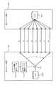
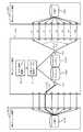
図15は、マルチパスモードで運用する場合の模式図である。第1ストレージ装置100のコントローラ101は、WWN情報管理テーブルT3及び外部デバイス情報テーブルT1を参照することにより、複数のパスP1〜P8を順番に切替ながら、第2ストレージ装置200にアクセスする。即ち、障害が発生していない場合、各アクセス処理の度に、例えば、P1、P2、P3、P4...の順番で、パスが切り替えて使用される。従って、ホスト10から多数のアクセスが要求された場合でも、各パスP1〜P8の待ち行列をそれぞれ短くできるため、高速に処理を行うことができる。一方、いずれかのパスに障害が検出された場合、そのパスは閉塞され、使用不能となる。この場合、第1ストレージ装置100は、正常なパスだけを順番に切替ながら、第2ストレージ装置200にアクセスする。 FIG. 15 is a schematic diagram when operating in the multipath mode. The
このように、本実施例では、第1ストレージ装置100と第2ストレージ装置200とを接続する複数のパスを順番に切替ながら、ホスト10からのアクセス要求を処理することができる。従って、第1実施例よりも高速に処理することができ、ストレージシステムの応答性を高めることができる。 As described above, in this embodiment, it is possible to process an access request from the
また、いずれかのパスに障害が検出された場合でも、そのパスを除いて運用を継続するため、耐障害性を向上させることができる。さらに、いずれかのパスを保守作業しながら、他のパスを順番に切り替えて処理を継続することもでき、高速応答性を確保しつつ、信頼性や保守性をより向上させることができる。 Even when a failure is detected in any of the paths, the operation is continued except for the path, so that the fault tolerance can be improved. Furthermore, while maintaining one of the paths, the other paths can be sequentially switched to continue the processing, and the reliability and maintainability can be further improved while ensuring high-speed response.
図16〜図19に基づいて第3実施例を説明する。本実施例では、所定の単位でパスの操作を可能としている。 A third embodiment will be described with reference to FIGS. In this embodiment, path operations can be performed in predetermined units.
図16は、パスの操作処理の概略を示すフローチャートである。本処理は、管理端末20のストレージ管理部22により実行することができる。まず、ユーザは、パスの構成を操作する画面を呼び出し(S110)、メニューを選択する(S111)。 FIG. 16 is a flowchart showing an outline of path operation processing. This process can be executed by the
操作メニューとしては、例えば、Externalポート単位でパスの構成を操作するメニューと、外部ストレージのポート単位でパスの構成を操作するメニューと、外部ボリューム240の単位でパスの構成を操作するメニューとを挙げることができる。 The operation menu includes, for example, a menu for operating the path configuration in units of external ports, a menu for operating the path configuration in units of external storage ports, and a menu for operating the path configuration in units of
Externalポート単位での操作をユーザが希望した場合、ユーザは、操作を希望するExternalポートを選択する(S112)。管理端末20は、選択されたExternalポートに接続されている全てのパスの構成を一覧形式で表示させる(S113)。ユーザは、表示された全てのパスまたは一部のパスを選択し、その構成変更を指示する(S114)。構成変更としては、例えば、パスの削除、パス状態の変更(Disconnect→Normal,Normal→Disconnect)等を挙げることができる。 When the user desires an operation in units of external ports, the user selects an external port for which the operation is desired (S112). The
管理端末20は、ユーザからの要求に応えて、ユーザの要求する内容を実現するコマンドを生成し、このコマンドを第1ストレージ装置100に送信する(S124)。このコマンドの詳細は、図10及び図11と共に既に述べた。 In response to the request from the user, the
ユーザが外部ストレージのポート単位(外部ポート単位)でパスの構成変更を希望する場合も前記同様に、構成変更を希望する外部ポートをユーザが選択する(S131)。管理端末20は、選択された外部ポートに接続されている全てのパスの構成を一覧形式で表示させる(S132)。ユーザは、表示された中から全部または一部のパスを選択し、構成変更を要求する(S133)。管理端末20は、必要なコマンドを生成して、第1ストレージ装置100に送信する(S134)。 When the user wishes to change the path configuration in units of external storage ports (in units of external ports), the user selects the external port for which configuration change is desired (S131). The
同様に、ユーザが外部ボリューム単位でのパスの構成変更を希望する場合、ユーザは、所望の外部ボリュームを選択する(S141)。管理端末20は、選択された外部ボリュームに接続されている全てのパスの構成を一覧形式で表示させる(S142)。ユーザは、表示されたパスの中から全部または一部のパスを選択し、構成変更を要求することができる(S143)。管理端末20は、要求された内容を実現させるためのコマンドを生成し、第1ストレージ装置100に送信する(S144)。 Similarly, when the user wishes to change the path configuration in units of external volumes, the user selects a desired external volume (S141). The
なお、複数のパスについて構成変更を指示する場合は、図10,図11で述べたようなコマンドを各パス毎にそれぞれ生成し、第1ストレージ装置100に送信する。 When instructing a configuration change for a plurality of paths, commands such as those described with reference to FIGS. 10 and 11 are generated for each path and transmitted to the
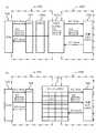
図17は、Externalポート単位でパスの構成変更を指示する場合の画面例である。領域G1の下側には、複数のタブメニューB1〜B3が設けられている。ユーザが、Externalポートの表示を指示するためのタブメニューB3を選択すると、領域G1には、複数のExternalポートが一覧表示される。この中から、ユーザは、所望のExternalポートをいずれか一つ選択することができる。 FIG. 17 shows an example of a screen when a path configuration change is instructed in units of external ports. A plurality of tab menus B1 to B3 are provided below the region G1. When the user selects a tab menu B3 for instructing display of an external port, a plurality of external ports are listed in the area G1. From this, the user can select any one of the desired external ports.
ユーザがExternalポートを選択すると(G11)、このポートに接続されている全てのパスの構成が、領域G2に一覧表示される。ユーザは、表示されたパスの中から構成変更を希望するパスをいずれか一つまたは複数(全部を含む。以下同様)を選択することができる。そして、例えば、コンテキストメニューのような形態で提供される操作メニューM1により、ユーザは、パスの回復やパスの切断等を指示することができる。 When the user selects an External port (G11), the configurations of all paths connected to this port are displayed in a list in the area G2. The user can select one or a plurality (including all, the same applies below) of the paths whose configuration is desired from the displayed paths. For example, the operation menu M1 provided in a form like a context menu allows the user to instruct path recovery, path disconnection, and the like.
図18は、外部ポート単位でパスの構成変更を指示する場合の画面例である。ユーザが、外部ポートの表示を指示するためのタブメニューB2を選択すると、領域G1には、複数の外部ポートが一覧表示される。この中から、ユーザは、所望の外部ポートをいずれか一つ選択することができる。 FIG. 18 is an example of a screen when a path configuration change is instructed in units of external ports. When the user selects a tab menu B2 for instructing display of external ports, a plurality of external ports are listed in the area G1. From this, the user can select any one of the desired external ports.
ユーザが外部ポートを選択すると(G12)、このポートに接続されている全てのパスの構成が、領域G2に一覧表示される。前記同様に、ユーザは、表示されたパスの中から構成変更を希望するパスをいずれか一つまたは複数を選択可能である。そして、ユーザは、操作メニューM1によって、パスの回復やパスの切断等を指示する。 When the user selects an external port (G12), the configurations of all paths connected to this port are listed in the area G2. Similarly to the above, the user can select any one or a plurality of paths whose configuration is desired from the displayed paths. Then, the user instructs path recovery, path disconnection, and the like through the operation menu M1.
図19は、外部ボリューム単位でパスの構成変更を指示する場合の画面例である。ユーザが、外部ボリュームの表示を指示するためのタブメニューB1を選択すると、領域G1には、外部ボリュームが一覧表示される。この中から、ユーザは、所望の外部ボリュームをいずれか一つ選択することができる。 FIG. 19 shows an example of a screen for instructing a path configuration change in units of external volumes. When the user selects a tab menu B1 for instructing display of an external volume, a list of external volumes is displayed in the area G1. From these, the user can select any one of the desired external volumes.
ユーザが外部ボリュームを選択すると(G13)、このボリューム240に接続されている全てのパスの構成が、領域G2に一覧表示される。ユーザは、表示されたパスの中から構成変更を希望するパスをいずれか一つまたは複数を選択することができる。ユーザは、操作メニューM1によって、パスの回復やパスの切断等を指示する。 When the user selects an external volume (G13), the configurations of all paths connected to the
このように本実施例では、所定の単位でパスの構成変更操作を行えるようにした。従って、例えば、保守作業等を行う場合に、その作業に関連する全てのパスを一括して切断状態に変更し、作業を行うことができる。この場合、使用可能なパスが残存していれば、保守作業とストレージサービスとを両立させることもできる。 As described above, in this embodiment, the path configuration change operation can be performed in a predetermined unit. Therefore, for example, when performing a maintenance work or the like, all paths related to the work can be collectively changed to a disconnected state and the work can be performed. In this case, if usable paths remain, maintenance work and storage service can be made compatible.
図20,図21に基づいて、第4実施例を説明する。本実施例では、第2ストレージ装置200を計画的に停止させたような場合に、障害発生と誤って認識されるのを未然に防止できるようにしている。 A fourth embodiment will be described with reference to FIGS. In this embodiment, when the
図20は、外部ストレージとしての第2ストレージ装置200を計画的に保守する場合の保守作業手順を示す概略フローチャートである。まず、ホスト10から第1ストレージ装置100へのアクセス要求(I/O)を停止させる(S151)。 FIG. 20 is a schematic flowchart showing a maintenance work procedure when the
次に、第1ストレージ装置100と第2ストレージ装置200とを結ぶ各パスの状態をそれぞれ切断状態に変更させる(S152)。この場合、前記実施例で述べたように、外部ポート単位または外部ボリューム単位で、パスの構成を変更することにより、作業性を高めることができる。 Next, the state of each path connecting the
このようにして保守準備を終えた後、保守要員は、第2ストレージ装置200の保守作業を開始する(S153)。保守作業を終えると(S154:YES)、切断されたパスの状態をそれぞれ通常状態に回復させる(S155)。そして、ホスト10から第1ストレージ装置100へのアクセス要求を許可する(S156)。 After completing the maintenance preparation in this way, the maintenance staff starts the maintenance work of the second storage device 200 (S153). When the maintenance work is completed (S154: YES), the state of the disconnected path is restored to the normal state (S155). Then, the access request from the
図21は、障害検出処理の概略を示すフローチャートである。この処理は、第1ストレージ装置100のコントローラ101により実行可能である。第1ストレージ装置100は、外部ストレージ(第2ストレージ装置200)との接続に使用されるパスであるか否かを判定する(S161)。 FIG. 21 is a flowchart showing an outline of the failure detection process. This process can be executed by the
外部接続用のパスでない場合(S161:NO)、第1ストレージ装置100は、そのパスに障害が発生しているか否かを判定する(S162)。障害が検出された場合(S162:YES)、第1ストレージ装置100は管理センタ30に障害発生を通知する(S163)。管理センタ30は、この通知を受信すると、例えば、保守要員に連絡する。 When the path is not an external connection path (S161: NO), the
一方、外部接続用のパスである場合(S161:YES)、第1ストレージ装置100は、そのパスが切断状態(Disconnect)であるか否かを判定する(S164)。その外部接続用パスが論理的に切断されていない場合(S164:NO)、第1ストレージ装置100は、既に述べたS162に移る。 On the other hand, when the path is an external connection path (S161: YES), the
これに対し、その外部接続用パスが切断状態にある場合(S164:YES)、第1ストレージ装置100は、障害が発生したか否かを判定することなく、本処理を終了する。即ち、論理的に切断された外部接続用のパスは、障害検出処理の対象とならず、無視される。 On the other hand, when the external connection path is in a disconnected state (S164: YES), the
従って、本実施例では、外部ストレージの保守作業を行う前に、外部接続用パスの状態を切断状態に変更させることにより、誤った通知が管理センタ30に送信されるのを未然に防止することができ、使い勝手が向上する。 Accordingly, in this embodiment, before the maintenance work of the external storage is performed, the state of the external connection path is changed to the disconnected state, thereby preventing an erroneous notification from being transmitted to the
図22は、第5実施例に係るストレージシステムの模式図である。図22に示すように、第1ストレージ装置100には、第2ストレージ装置200に加えて、第3ストレージ装置200Aを接続することができる。 FIG. 22 is a schematic diagram of a storage system according to the fifth embodiment. As shown in FIG. 22, in addition to the
第1ストレージ装置100内には、複数のV−VOL162Vが設けられており、これら各V−VOL162Vには、それぞれ異なる外部ストレージ200,200A内のボリューム240,240Aがマッピングされている。 A plurality of V-
そして、第2ストレージ装置200は、マルチパスモードで運用されており、第3ストレージ装置200Aはシングルパスモードで運用されている。従って、例えば、高速応答性が要求される場合は、第2ストレージ装置200のボリュームを利用し、高速応答性よりも耐障害性が重視されるような場合は、第3ストレージ装置200Aのボリュームを利用することができる。 The
なお、本発明は、上述した各実施例に限定されない。当業者であれば、本発明の範囲内で、種々の追加や変更等を行うことができる。例えば、シングルパスモードとマルチパスモードとを、運用途中で動的に切り替えることも可能である。また、例えば、それぞれ複数のパスを有する複数のグループを形成し、各パスグループ毎にそれぞれシングルパスモードまたはマルチパスモードを適用可能な場合もある。 In addition, this invention is not limited to each Example mentioned above. A person skilled in the art can make various additions and changes within the scope of the present invention. For example, it is possible to dynamically switch between a single path mode and a multipath mode during operation. Further, for example, there are cases where a plurality of groups each having a plurality of paths are formed, and a single path mode or a multipath mode can be applied to each path group.
1,2…ストレージ装置、1A…仮想ボリューム、1B…制御部、1C…マッピング情報、EP1〜EP3…外部接続用ポート、2A…実ボリューム、2B…外部LUN、P1〜P3…ポート、3…スイッチ、4…ホスト、5…管理端末、10…ホスト、11…HBA、12…アプリケーションプログラム、20…管理端末、21…ポート、22…ストレージ管理部、30…管理センタ、100…第1ストレージ装置(メインストレージ)、101…コントローラ、110…チャネルアダプタ(CHA)、111A…ターゲットポート、111B…外部接続用ポート(Externalポート)、120…ディスクアダプタ(DKA)、130…キャッシュメモリ、140…共有メモリ、150…接続制御部、160…記憶部、161…ディスクドライブ(PDEV)、162V…中間仮想記憶デバイス(V−VOL)、163…内部ボリューム(LDEV)、163V…仮想ボリューム、164…LU、165…コマンドデバイス(CMD)、200…第2ストレージ装置(外部ストレージ)、210…コントローラ、211…ポート、220…ディスクドライブ、240…論理ボリューム(LDEV)、T1…外部デバイス情報テーブル DESCRIPTION OF
Claims (19)
Translated fromJapanese前記第1ストレージ装置と複数の通信パスを介して接続され、前記仮想ボリュームに対応付けられる実ボリュームを有する第2ストレージ装置と、
前記各通信パスによって前記仮想ボリュームと前記実ボリュームとをそれぞれ接続し、前記実ボリュームを前記仮想ボリュームのデータ格納先ボリュームとしてマッピングするマッピング管理部と、
前記マッピング管理部により管理されている前記仮想ボリュームと前記実ボリュームとのマッピング情報に基づいて、前記ホストから前記仮想ボリュームへのアクセス要求を処理する制御部と、を備え、
前記制御部は、前記各通信パスのうち少なくともいずれか一つ以上の通信パスを選択して、前記アクセス要求を処理可能であるストレージシステム。A first storage device having a virtual volume used by the host;
A second storage device connected to the first storage device via a plurality of communication paths and having a real volume associated with the virtual volume;
A mapping management unit that connects the virtual volume and the real volume through the communication paths, and maps the real volume as a data storage destination volume of the virtual volume;
A control unit that processes an access request from the host to the virtual volume based on mapping information between the virtual volume and the real volume managed by the mapping management unit,
The storage system is capable of processing the access request by selecting at least one communication path among the communication paths.
前記制御部は、前記優先度に基づいて、使用可能な前記各通信パスのうち少なくともいずれか一つの通信パスを選択して使用する請求項1に記載のストレージシステム。Each communication path has a priority set in advance,
The storage system according to claim 1, wherein the control unit selects and uses at least one of the available communication paths based on the priority.
前記各通信パスのいずれかにおいて障害の発生が検出された場合、この障害の発生した通信パスの状態が前記使用不能状態に設定されている場合は、前記障害の発生を無視する請求項9に記載のストレージシステム。The control unit further includes a failure detection unit that detects whether or not a failure has occurred in each of the communication paths.
The occurrence of the failure is ignored when the occurrence of a failure is detected in any of the communication paths, and the state of the communication path in which the failure has occurred is set to the unusable state. The described storage system.
前記制御部は、ストレージ装置単位で、前記第1モードまたは前記第2モードをそれぞれ適用可能である請求項13に記載のストレージシステム。A third storage device connected to the first storage device via a plurality of other communication paths and having another real volume associated with another virtual volume of the first storage device;
The storage system according to claim 13, wherein the control unit can apply the first mode or the second mode in units of storage devices.
前記各通信パスのうちいずれか一つの通信パスを用い、前記マッピング情報に基づいて、ホストから前記仮想ボリュームへのアクセス要求を処理する第2ステップと、
前記各通信パスに障害が発生したか否かをそれぞれ検出する第3ステップと、
前記各通信パスのうち使用中の通信パスについて前記障害が発生した場合は、前記各通信パスのうち使用可能な通信パスを少なくともいずれか一つ選択する第4ステップと、
前記選択された通信パスを使用して前記ホストからのアクセス要求を処理する第5ステップと、
を含むストレージシステムのパス制御方法。A first management unit that manages the mapping information indicating the correspondence between the virtual volume and the real volume by connecting the virtual volume of the first storage device and the real volume of the second storage device via a plurality of communication paths, respectively. Steps,
A second step of processing an access request from the host to the virtual volume based on the mapping information using any one of the communication paths;
A third step of detecting whether or not a failure has occurred in each of the communication paths;
A fourth step of selecting at least one usable communication path from among the communication paths when the failure has occurred with respect to a communication path in use among the communication paths;
A fifth step of processing an access request from the host using the selected communication path;
Storage system path control method including
前記第4ステップは、前記各通信パスのうち、使用可能状態にある通信パスの中で最も前記優先度が高く設定されている通信パスを一つ選択する請求項15に記載のストレージシステムのパス制御方法。The mapping information includes at least the virtual volume identification information for identifying the virtual volume, the real volume identification information for identifying the real volume, and the real volume using the communication paths. Corresponding each path information for accessing the volume, status information indicating whether each communication path is usable or unusable, and priority information indicating the priority of each communication path And
The storage system path according to claim 15, wherein the fourth step selects one of the communication paths that has the highest priority among the communication paths in an available state. Control method.
前記各パス情報は、前記各第1ポートをそれぞれ識別するための第1ポート情報と、前記各第2ポートをそれぞれ識別するための第2ポート情報とを対応付けることにより構成されており、
前記第6ステップは、前記マッピング情報の全部または一部を、前記第1ポートまたは前記第2ポートにそれぞれ接続されている少なくとも一つ以上の前記通信パス毎に、それぞれ更新可能である請求項17に記載のストレージシステムのパス制御方法。The first storage device further includes a plurality of first ports, and the second storage device further includes a plurality of second ports,
Each path information is configured by associating first port information for identifying each first port with second port information for identifying each second port,
18. The sixth step can update all or a part of the mapping information for each of at least one or more of the communication paths connected to the first port or the second port, respectively. The path control method of the storage system as described in 1.
前記第1ストレージ装置は、
前記第2ストレージ装置の有する記憶デバイスの記憶領域上に前記各通信パスを介してそれぞれ接続される仮想中間記憶デバイスと、
この仮想中間記憶デバイスの記憶領域上に設けられる仮想ボリュームと、
前記ホスト及び前記第2ストレージ装置との間でそれぞれデータ通信を行う通信制御部と、
前記通信制御部により使用されるメモリ部と、
前記メモリ部に格納され、前記仮想中間記憶デバイスに前記第2ストレージ装置の記憶デバイスをマッピングさせるためのマッピングテーブルと、
を備え、
前記制御部は、前記各通信パスのうちいずれか一つの通信パスを用い、前記マッピングテーブルに基づいて、前記ホストから前記仮想ボリュームへのアクセス要求を処理するステップと、
前記各通信パスに障害が発生したか否かをそれぞれ検出するステップと、
前記各通信パスのうち使用中の通信パスについて前記障害が発生した場合は、前記各通信パスのうち使用可能な通信パスを少なくともいずれか一つ選択するステップと、
前記選択された通信パスを使用して前記ホストからのアクセス要求を処理するステップとを実行し、
前記管理装置は、前記マッピングテーブルの全部または一部を、予め設定された所定の接続点に接続されている少なくとも一つ以上の前記通信パス毎に、それぞれ更新させる構成管理部を備えている、
ストレージシステム。
A first storage device that processes an access request from a host; a second storage device connected to the first storage device via a plurality of communication paths; and a management device connected to the first storage device. Storage system,
The first storage device
A virtual intermediate storage device connected via a communication path to a storage area of a storage device of the second storage device;
A virtual volume provided on the storage area of the virtual intermediate storage device;
A communication control unit that performs data communication between the host and the second storage device, and
A memory unit used by the communication control unit;
A mapping table stored in the memory unit and for mapping the storage device of the second storage device to the virtual intermediate storage device;
With
The control unit uses any one of the communication paths and processes an access request from the host to the virtual volume based on the mapping table;
Detecting whether or not a failure has occurred in each of the communication paths;
When the failure has occurred for a communication path that is in use among the communication paths, the step of selecting at least one communication path that can be used among the communication paths;
Processing an access request from the host using the selected communication path; and
The management device includes a configuration management unit that updates all or a part of the mapping table for each of at least one or more communication paths connected to a predetermined connection point set in advance.
Storage system.
Priority Applications (4)
| Application Number | Priority Date | Filing Date | Title |
|---|---|---|---|
| JP2004372713AJP2006178811A (en) | 2004-12-24 | 2004-12-24 | Storage system and storage system path control method |
| US11/070,182US20060143332A1 (en) | 2004-12-24 | 2005-03-03 | Storage system and method of storage system path control |
| EP05254525AEP1674983A1 (en) | 2004-12-24 | 2005-07-20 | Storage system and method of storage system path control |
| US12/153,302US7603507B2 (en) | 2004-12-24 | 2008-05-16 | Storage system and method of storage system path control |
Applications Claiming Priority (1)
| Application Number | Priority Date | Filing Date | Title |
|---|---|---|---|
| JP2004372713AJP2006178811A (en) | 2004-12-24 | 2004-12-24 | Storage system and storage system path control method |
Publications (1)
| Publication Number | Publication Date |
|---|---|
| JP2006178811Atrue JP2006178811A (en) | 2006-07-06 |
Family
ID=35149481
Family Applications (1)
| Application Number | Title | Priority Date | Filing Date |
|---|---|---|---|
| JP2004372713APendingJP2006178811A (en) | 2004-12-24 | 2004-12-24 | Storage system and storage system path control method |
Country Status (3)
| Country | Link |
|---|---|
| US (2) | US20060143332A1 (en) |
| EP (1) | EP1674983A1 (en) |
| JP (1) | JP2006178811A (en) |
Cited By (6)
| Publication number | Priority date | Publication date | Assignee | Title |
|---|---|---|---|---|
| JP2008059089A (en)* | 2006-08-29 | 2008-03-13 | Hitachi Ltd | Storage system and data management migration method |
| JP2009140179A (en)* | 2007-12-05 | 2009-06-25 | Fujitsu Ltd | Storage system and root switch |
| EP2107449A2 (en) | 2008-03-31 | 2009-10-07 | Hitachi, Ltd. | Storage system and control method of storage system |
| JP2009259031A (en)* | 2008-04-17 | 2009-11-05 | Hitachi Ltd | Method of managing paths for externally-connected storage system and method of detecting fault site |
| JP2010205159A (en)* | 2009-03-05 | 2010-09-16 | Hitachi Ltd | Information processor and method for managing configuration information acquired from storage system |
| JP2019003586A (en)* | 2017-06-20 | 2019-01-10 | 富士通株式会社 | Storage control device and path switching control program |
Families Citing this family (71)
| Publication number | Priority date | Publication date | Assignee | Title |
|---|---|---|---|---|
| US7210068B1 (en)* | 2002-03-06 | 2007-04-24 | Network Appliance, Inc. | System and method for multipath I/O support for fibre channel devices |
| WO2005109212A2 (en) | 2004-04-30 | 2005-11-17 | Commvault Systems, Inc. | Hierarchical systems providing unified of storage information |
| US8266406B2 (en) | 2004-04-30 | 2012-09-11 | Commvault Systems, Inc. | System and method for allocation of organizational resources |
| JP2006178720A (en)* | 2004-12-22 | 2006-07-06 | Hitachi Ltd | Storage system |
| JP4718285B2 (en)* | 2005-09-22 | 2011-07-06 | 株式会社日立製作所 | Computer system having file management function, storage device, and file management method |
| US20110010518A1 (en)* | 2005-12-19 | 2011-01-13 | Srinivas Kavuri | Systems and Methods for Migrating Components in a Hierarchical Storage Network |
| US7651593B2 (en) | 2005-12-19 | 2010-01-26 | Commvault Systems, Inc. | Systems and methods for performing data replication |
| US8572330B2 (en)* | 2005-12-19 | 2013-10-29 | Commvault Systems, Inc. | Systems and methods for granular resource management in a storage network |
| US8661216B2 (en)* | 2005-12-19 | 2014-02-25 | Commvault Systems, Inc. | Systems and methods for migrating components in a hierarchical storage network |
| EP1974296B8 (en) | 2005-12-19 | 2016-09-21 | Commvault Systems, Inc. | Systems and methods for performing data replication |
| US7606844B2 (en) | 2005-12-19 | 2009-10-20 | Commvault Systems, Inc. | System and method for performing replication copy storage operations |
| KR100862659B1 (en)* | 2006-01-04 | 2008-10-10 | 삼성전자주식회사 | Methods and devices for accessing internet storage |
| US20070199043A1 (en)* | 2006-02-06 | 2007-08-23 | Morris Richard M | Multi-channel high-bandwidth media network |
| US9032164B2 (en)* | 2006-02-17 | 2015-05-12 | Emulex Corporation | Apparatus for performing storage virtualization |
| JP2007272357A (en)* | 2006-03-30 | 2007-10-18 | Toshiba Corp | Storage cluster system, data processing method, and program |
| JP2007310656A (en)* | 2006-05-18 | 2007-11-29 | Hitachi Ltd | Computer system and logical path difference detection method |
| US7792019B1 (en)* | 2006-06-22 | 2010-09-07 | Verizon Patent And Licensing Inc. | Call management |
| US7937481B1 (en) | 2006-06-27 | 2011-05-03 | Emc Corporation | System and methods for enterprise path management |
| US7962567B1 (en)* | 2006-06-27 | 2011-06-14 | Emc Corporation | Systems and methods for disabling an array port for an enterprise |
| US8726242B2 (en) | 2006-07-27 | 2014-05-13 | Commvault Systems, Inc. | Systems and methods for continuous data replication |
| US20080147878A1 (en)* | 2006-12-15 | 2008-06-19 | Rajiv Kottomtharayil | System and methods for granular resource management in a storage network |
| US8024426B2 (en)* | 2007-05-11 | 2011-09-20 | Texas Memory Systems, Inc. | Non-disruptive data path upgrade using target mobility |
| US7774094B2 (en) | 2007-06-28 | 2010-08-10 | International Business Machines Corporation | Selecting a source cluster by measuring system factors, calculating a mount-to-dismount lifespan, and selecting the source cluster in response to the lifespan and a user policy |
| US8204980B1 (en) | 2007-06-28 | 2012-06-19 | Emc Corporation | Storage array network path impact analysis server for path selection in a host-based I/O multi-path system |
| US8918537B1 (en) | 2007-06-28 | 2014-12-23 | Emc Corporation | Storage array network path analysis server for enhanced path selection in a host-based I/O multi-path system |
| JP4994128B2 (en)* | 2007-06-28 | 2012-08-08 | 株式会社日立製作所 | Storage system and management method in storage system |
| JP2009129261A (en)* | 2007-11-26 | 2009-06-11 | Hitachi Ltd | Storage system and storage system external volume connection path search method |
| US8341251B2 (en)* | 2008-01-03 | 2012-12-25 | International Business Machines Corporation | Enabling storage area network component migration |
| US8032730B2 (en) | 2008-05-15 | 2011-10-04 | Hitachi, Ltd. | Method and apparatus for I/O priority control in storage systems |
| JP4548524B2 (en)* | 2008-07-29 | 2010-09-22 | ソニー株式会社 | COMMUNICATION DEVICE, PROGRAM, COMMUNICATION METHOD, AND COMMUNICATION SYSTEM |
| KR100994127B1 (en)* | 2008-08-28 | 2010-11-15 | 한국전자통신연구원 | Packet Processing Methods to Improve the Performance of Ethernet Switches |
| US9495382B2 (en) | 2008-12-10 | 2016-11-15 | Commvault Systems, Inc. | Systems and methods for performing discrete data replication |
| US8204859B2 (en) | 2008-12-10 | 2012-06-19 | Commvault Systems, Inc. | Systems and methods for managing replicated database data |
| US8112562B2 (en) | 2008-12-11 | 2012-02-07 | Hitachi, Ltd. | Path changeover support device and method |
| JP5024329B2 (en)* | 2009-05-08 | 2012-09-12 | 富士通株式会社 | Relay program, relay device, relay method, system |
| US8417849B2 (en)* | 2009-10-07 | 2013-04-09 | International Business Machines Corporation | Apparatus and method to adjust a multi-path device reservation |
| US8504517B2 (en) | 2010-03-29 | 2013-08-06 | Commvault Systems, Inc. | Systems and methods for selective data replication |
| US8504515B2 (en) | 2010-03-30 | 2013-08-06 | Commvault Systems, Inc. | Stubbing systems and methods in a data replication environment |
| US8725698B2 (en) | 2010-03-30 | 2014-05-13 | Commvault Systems, Inc. | Stub file prioritization in a data replication system |
| US8589347B2 (en) | 2010-05-28 | 2013-11-19 | Commvault Systems, Inc. | Systems and methods for performing data replication |
| US8619555B2 (en)* | 2010-11-17 | 2013-12-31 | Netapp, Inc. | Method and system for path selection in a network |
| JP5100854B2 (en)* | 2011-01-31 | 2012-12-19 | 株式会社東芝 | Communication apparatus and communication method |
| WO2012114378A1 (en)* | 2011-02-23 | 2012-08-30 | Hitachi, Ltd. | Data storage system and management method of the data storage system |
| US8938566B2 (en) | 2011-03-17 | 2015-01-20 | American Megatrends, Inc. | Data storage system for managing serial interface configuration based on detected activity |
| JP5668982B2 (en)* | 2011-03-31 | 2015-02-12 | 日本電気株式会社 | Storage system, access path status update method, and access path status update program |
| CN103765580B (en)* | 2011-08-31 | 2016-11-16 | 飞思卡尔半导体公司 | There is, in IC apparatus and identification outside signal path, the method disconnected |
| US8984220B1 (en)* | 2011-09-30 | 2015-03-17 | Emc Corporation | Storage path management host view |
| US8819307B1 (en)* | 2011-12-29 | 2014-08-26 | Emc Corporation | Identification and use of preferred path groups in host computer based on differential performance |
| US11474704B2 (en)* | 2012-05-18 | 2022-10-18 | Atto Technology, Inc. | Target path selection for storage controllers |
| US8832372B2 (en)* | 2012-05-24 | 2014-09-09 | Netapp, Inc. | Network storage systems having clustered raids for improved redundancy and load balancing |
| JP5890521B2 (en)* | 2012-06-07 | 2016-03-22 | 株式会社日立製作所 | Motion controller device and communication method in the same device |
| US8925059B2 (en)* | 2012-06-08 | 2014-12-30 | Lockheed Martin Corporation | Dynamic trust connection |
| US10379988B2 (en) | 2012-12-21 | 2019-08-13 | Commvault Systems, Inc. | Systems and methods for performance monitoring |
| US9258242B1 (en) | 2013-12-19 | 2016-02-09 | Emc Corporation | Path selection using a service level objective |
| RU2013156784A (en) | 2013-12-20 | 2015-06-27 | ИЭмСи КОРПОРЕЙШН | METHOD AND DEVICE FOR SELECTING THE READING AND WRITING DATA ROUTE |
| US9213588B2 (en)* | 2014-01-10 | 2015-12-15 | Avago Technologies General Ip (Singapore) Pte. Ltd. | Fault detection and identification in a multi-initiator system |
| WO2015121998A1 (en)* | 2014-02-17 | 2015-08-20 | 株式会社日立製作所 | Storage system |
| US9268496B2 (en) | 2014-07-11 | 2016-02-23 | International Business Machines Corporation | Choosing a multipath I/O (MPIO) path control module (PCM) for a logical unit number (LUN) on a host that supports multiple PCMS |
| US10275320B2 (en) | 2015-06-26 | 2019-04-30 | Commvault Systems, Inc. | Incrementally accumulating in-process performance data and hierarchical reporting thereof for a data stream in a secondary copy operation |
| US10248494B2 (en) | 2015-10-29 | 2019-04-02 | Commvault Systems, Inc. | Monitoring, diagnosing, and repairing a management database in a data storage management system |
| US11449365B2 (en)* | 2016-01-04 | 2022-09-20 | Trilio Data Inc. | Ubiquitous and elastic workload orchestration architecture of hybrid applications/services on hybrid cloud |
| US10785295B2 (en)* | 2016-06-30 | 2020-09-22 | Intel Corporation | Fabric encapsulated resilient storage |
| US10831591B2 (en) | 2018-01-11 | 2020-11-10 | Commvault Systems, Inc. | Remedial action based on maintaining process awareness in data storage management |
| JP6751423B2 (en)* | 2018-07-31 | 2020-09-02 | 株式会社日立製作所 | Storage device and control method thereof |
| US20200192572A1 (en) | 2018-12-14 | 2020-06-18 | Commvault Systems, Inc. | Disk usage growth prediction system |
| US11042318B2 (en) | 2019-07-29 | 2021-06-22 | Commvault Systems, Inc. | Block-level data replication |
| US11003357B2 (en)* | 2019-09-13 | 2021-05-11 | EMC IP Holding Company LLC | Managing single path communication between a host and a storage system |
| JP2021047786A (en)* | 2019-09-20 | 2021-03-25 | 富士通株式会社 | Storage controller, storage device, and determination program |
| CN111723054A (en)* | 2020-06-29 | 2020-09-29 | 湖北亿咖通科技有限公司 | Method for accessing external storage device |
| US11809285B2 (en) | 2022-02-09 | 2023-11-07 | Commvault Systems, Inc. | Protecting a management database of a data storage management system to meet a recovery point objective (RPO) |
| US12056018B2 (en) | 2022-06-17 | 2024-08-06 | Commvault Systems, Inc. | Systems and methods for enforcing a recovery point objective (RPO) for a production database without generating secondary copies of the production database |
Citations (6)
| Publication number | Priority date | Publication date | Assignee | Title |
|---|---|---|---|---|
| JPH01318323A (en)* | 1988-06-17 | 1989-12-22 | Nippon Signal Co Ltd:The | System switching method in standby type multiplex system |
| JPH04253424A (en)* | 1991-01-30 | 1992-09-09 | Nec Corp | Data communication equipment |
| JP2000242434A (en)* | 1998-12-22 | 2000-09-08 | Hitachi Ltd | Storage system |
| JP2003099384A (en)* | 2001-09-20 | 2003-04-04 | Nec Corp | Load-sharing system, host computer for the load-sharing system, and load-sharing program |
| JP2003131897A (en)* | 2001-10-24 | 2003-05-09 | Hitachi Ltd | Storage with built-in ports |
| JP2004110367A (en)* | 2002-09-18 | 2004-04-08 | Hitachi Ltd | Storage device system control method, storage control device, and storage device system |
Family Cites Families (15)
| Publication number | Priority date | Publication date | Assignee | Title |
|---|---|---|---|---|
| US5848072A (en)* | 1995-08-10 | 1998-12-08 | Motorola, Inc. | Method of and apparatus for communicating messages |
| US5680640A (en) | 1995-09-01 | 1997-10-21 | Emc Corporation | System for migrating data by selecting a first or second transfer means based on the status of a data element map initialized to a predetermined state |
| US6173346B1 (en)* | 1997-05-13 | 2001-01-09 | Micron Electronics, Inc. | Method for hot swapping a programmable storage adapter using a programmable processor for selectively enabling or disabling power to adapter slot in response to respective request signals |
| US6237008B1 (en)* | 1998-07-20 | 2001-05-22 | International Business Machines Corporation | System and method for enabling pair-pair remote copy storage volumes to mirror data in another storage volume |
| US6857026B1 (en)* | 1999-12-14 | 2005-02-15 | Nortel Networks Limited | Using alternate routes for fail-over in a communication network |
| JP4771615B2 (en)* | 2000-06-02 | 2011-09-14 | コンパック インフォメーション テクノロジーズ グループ リミテッド パートナーシップ | Virtual storage system |
| JP2001350707A (en)* | 2000-06-06 | 2001-12-21 | Hitachi Ltd | Information processing system and storage device allocation method |
| US6457109B1 (en)* | 2000-08-18 | 2002-09-24 | Storage Technology Corporation | Method and apparatus for copying data from one storage system to another storage system |
| US6728736B2 (en)* | 2001-03-14 | 2004-04-27 | Storage Technology Corporation | System and method for synchronizing a data copy using an accumulation remote copy trio |
| US6948038B2 (en)* | 2001-07-24 | 2005-09-20 | Microsoft Corporation | System and method for backing up and restoring data |
| US7421509B2 (en)* | 2001-09-28 | 2008-09-02 | Emc Corporation | Enforcing quality of service in a storage network |
| JP4704659B2 (en)* | 2002-04-26 | 2011-06-15 | 株式会社日立製作所 | Storage system control method and storage control device |
| JP2004021557A (en)* | 2002-06-14 | 2004-01-22 | Hitachi Ltd | Program, information processing method, information processing device, and storage device |
| JP3913176B2 (en)* | 2003-01-10 | 2007-05-09 | キヤノン株式会社 | Monitoring device, management device, control method, program, and storage medium |
| JP4497957B2 (en)* | 2004-03-05 | 2010-07-07 | 株式会社日立製作所 | Storage control system |
- 2004
- 2004-12-24JPJP2004372713Apatent/JP2006178811A/enactivePending
- 2005
- 2005-03-03USUS11/070,182patent/US20060143332A1/ennot_activeAbandoned
- 2005-07-20EPEP05254525Apatent/EP1674983A1/ennot_activeCeased
- 2008
- 2008-05-16USUS12/153,302patent/US7603507B2/ennot_activeExpired - Fee Related
Patent Citations (6)
| Publication number | Priority date | Publication date | Assignee | Title |
|---|---|---|---|---|
| JPH01318323A (en)* | 1988-06-17 | 1989-12-22 | Nippon Signal Co Ltd:The | System switching method in standby type multiplex system |
| JPH04253424A (en)* | 1991-01-30 | 1992-09-09 | Nec Corp | Data communication equipment |
| JP2000242434A (en)* | 1998-12-22 | 2000-09-08 | Hitachi Ltd | Storage system |
| JP2003099384A (en)* | 2001-09-20 | 2003-04-04 | Nec Corp | Load-sharing system, host computer for the load-sharing system, and load-sharing program |
| JP2003131897A (en)* | 2001-10-24 | 2003-05-09 | Hitachi Ltd | Storage with built-in ports |
| JP2004110367A (en)* | 2002-09-18 | 2004-04-08 | Hitachi Ltd | Storage device system control method, storage control device, and storage device system |
Cited By (10)
| Publication number | Priority date | Publication date | Assignee | Title |
|---|---|---|---|---|
| JP2008059089A (en)* | 2006-08-29 | 2008-03-13 | Hitachi Ltd | Storage system and data management migration method |
| JP2009140179A (en)* | 2007-12-05 | 2009-06-25 | Fujitsu Ltd | Storage system and root switch |
| EP2107449A2 (en) | 2008-03-31 | 2009-10-07 | Hitachi, Ltd. | Storage system and control method of storage system |
| JP2009245379A (en)* | 2008-03-31 | 2009-10-22 | Hitachi Ltd | Storage system and control method of storage system |
| US8086768B2 (en) | 2008-03-31 | 2011-12-27 | Hitachi, Ltd. | Storage system and control method of storage system |
| US8578073B2 (en) | 2008-03-31 | 2013-11-05 | Hitachi, Ltd. | Storage system and control method of storage system |
| JP2009259031A (en)* | 2008-04-17 | 2009-11-05 | Hitachi Ltd | Method of managing paths for externally-connected storage system and method of detecting fault site |
| US7836350B2 (en) | 2008-04-17 | 2010-11-16 | Hitachi, Ltd. | Method of managing paths for an externally-connected storage system and method of detecting a fault site |
| JP2010205159A (en)* | 2009-03-05 | 2010-09-16 | Hitachi Ltd | Information processor and method for managing configuration information acquired from storage system |
| JP2019003586A (en)* | 2017-06-20 | 2019-01-10 | 富士通株式会社 | Storage control device and path switching control program |
Also Published As
| Publication number | Publication date |
|---|---|
| EP1674983A1 (en) | 2006-06-28 |
| US20060143332A1 (en) | 2006-06-29 |
| US7603507B2 (en) | 2009-10-13 |
| US20080228987A1 (en) | 2008-09-18 |
Similar Documents
| Publication | Publication Date | Title |
|---|---|---|
| JP2006178811A (en) | Storage system and storage system path control method | |
| US8683157B2 (en) | Storage system and virtualization method | |
| JP5057656B2 (en) | Storage system and storage system operation method | |
| JP4307202B2 (en) | Storage system and storage control device | |
| US9619171B2 (en) | Storage system and virtualization method | |
| JP4555036B2 (en) | Storage apparatus and device switching control method of storage apparatus | |
| CN101075177B (en) | Computer system | |
| JP2006127028A (en) | Storage system and storage control device | |
| WO2011135636A1 (en) | Computer system and method for controlling same | |
| JP4634136B2 (en) | Storage control system | |
| JP2008134712A (en) | File sharing system, file sharing apparatus, and file sharing volume migration method | |
| JP2006092120A (en) | Storage device and storage device write access processing method | |
| JP4648751B2 (en) | Storage control system and storage control method | |
| JP2006134021A (en) | Storage system and storage system configuration management method | |
| JP2007072519A (en) | Storage system and storage system control method | |
| JP5052257B2 (en) | Storage system and storage control device | |
| JP2009129261A (en) | Storage system and storage system external volume connection path search method | |
| US7424572B2 (en) | Storage device system interfacing open-system host computer input/output interfaces | |
| JP5335848B2 (en) | Storage system and storage system operation method |
Legal Events
| Date | Code | Title | Description |
|---|---|---|---|
| A621 | Written request for application examination | Free format text:JAPANESE INTERMEDIATE CODE: A621 Effective date:20070913 | |
| A977 | Report on retrieval | Free format text:JAPANESE INTERMEDIATE CODE: A971007 Effective date:20100524 | |
| A131 | Notification of reasons for refusal | Free format text:JAPANESE INTERMEDIATE CODE: A131 Effective date:20100601 | |
| A521 | Written amendment | Free format text:JAPANESE INTERMEDIATE CODE: A523 Effective date:20100712 | |
| A131 | Notification of reasons for refusal | Free format text:JAPANESE INTERMEDIATE CODE: A131 Effective date:20101222 | |
| A02 | Decision of refusal | Free format text:JAPANESE INTERMEDIATE CODE: A02 Effective date:20110426 |