JP2006174105A - Electronic camera and program - Google Patents
Electronic camera and programDownload PDFInfo
- Publication number
- JP2006174105A JP2006174105AJP2004364022AJP2004364022AJP2006174105AJP 2006174105 AJP2006174105 AJP 2006174105AJP 2004364022 AJP2004364022 AJP 2004364022AJP 2004364022 AJP2004364022 AJP 2004364022AJP 2006174105 AJP2006174105 AJP 2006174105A
- Authority
- JP
- Japan
- Prior art keywords
- image
- blur
- unit
- subject
- electronic camera
- Prior art date
- Legal status (The legal status is an assumption and is not a legal conclusion. Google has not performed a legal analysis and makes no representation as to the accuracy of the status listed.)
- Granted
Links
Images


Landscapes
- Studio Devices (AREA)
Abstract
Translated fromJapaneseDescription
Translated fromJapanese本発明は、デジタルカメラ等の電子カメラにおいてブレのない撮影画像を得る撮影技術に関する。 The present invention relates to a shooting technique for obtaining a blur-free shot image in an electronic camera such as a digital camera.
カメラで撮影を行う場合はシャッターキー等を押して撮像指示を行って撮影するのが普通であり、三脚等のカメラ固定装置にカメラを固定せず、手で構えて撮影指示を行うとシャッターキーを押す際に手ブレが生じてブレた画像が撮影されてしまうといった問題があった。
手ブレを抑制するための従来技術として、手ブレを検出して警告を発生して撮影者に、しっかりカメラを保持するようユーザを促すものがある。When shooting with a camera, it is normal to press the shutter key, etc. to instruct the camera to take a picture, and instead of fixing the camera to a camera fixing device such as a tripod, hold the camera with your hand and hold the shutter key. There has been a problem that when the button is pressed, camera shake occurs and a blurred image is shot.
As a conventional technique for suppressing camera shake, there is a technique that detects a camera shake and generates a warning to prompt the photographer to hold the camera firmly.
このようなカメラとして、加速度センサの出力が所定値より大きいことを判定する第1判定手段と、画像信号が所定量以上に変化した時を判定する第2判定手段とを設け、第1、第2の判定手段の判定結果に従って警告を行うカメラや(例えば、特許文献1参照)、シャッター操作時の撮影画像を保存すると共に、シャッター操作前後の画像を自動的に取得し、シャッター操作時の画像と比較して手ブレを検出したとき警告するように構成した電子スチルカメラがある(例えば、特許文献2参照)。 As such a camera, there are provided first determination means for determining that the output of the acceleration sensor is greater than a predetermined value, and second determination means for determining when the image signal has changed to a predetermined amount or more. A camera that issues a warning according to the determination result of the determination unit 2 (see, for example, Patent Document 1), stores a captured image at the time of the shutter operation, automatically acquires images before and after the shutter operation, and images at the time of the shutter operation There is an electronic still camera configured to warn when a camera shake is detected as compared with (see, for example, Patent Document 2).
また、デジタルカメラのような電子静止画システムを対象とした電子的手ブレ補正方式の手ブレ補正装置がある。
このような装置として、手ブレ量を検出する手ブレ検出手段と、手ブレ検出手段で検出された手ブレ量が所定の範囲内にあるタイミングにのみ撮像素子を露光する露光制御手段を備えた電子静止画システムがある(例えば、特許文献3参照)。
As such an apparatus, there is provided a camera shake detecting means for detecting a camera shake amount, and an exposure control means for exposing the image sensor only at a timing when the camera shake amount detected by the camera shake detecting means is within a predetermined range. There is an electronic still image system (see, for example, Patent Document 3).
上記特許文献1では所定量以上の被写体ブレが生ずるたびに警告表示するので、撮影者はそのたびにカメラを持ち直して安定させてシャッターを押して撮影することができるが、画像のブレは手ブレと被写体の動きによるブレ(以下、動体ブレ)があり、カメラを持ち直すことにより手ブレをなくすことができたとしても被写体のブレを抑制することはできないので、被写体が動いた場合に動体ブレのある画像が撮影されてしまうといった課題があった。 In
また、上記特許文献2に開示の技術ではシャッター操作時に手ブレが生じた場合そのブレを検出して警告するので、その場で撮り直しができるという利点があるが、未然に手ブレを防止することができないし、上記特許文献1の場合と同様、被写体が動いた場合に動体ブレのある画像が撮影されてしまうといった課題があった。 In addition, the technique disclosed in
また、上記特許文献3に開示の技術によれば、手ブレ検出手段で検出された手ブレ量を表す手ブレ信号が或る範囲内にあるタイミングにのみ露光を行うようにすれば、被写体位置の安定した画面のみが得られるようになるので、手ブレを抑制した静止画を撮影することができるが、上記特許文献1及び特許文献2と同様、被写体が動いた場合に動体ブレのある画像が撮影されてしまうといった課題があった。 Further, according to the technique disclosed in
本発明は上記従来技術の課題を解決するためになされたものであり、被写体のブレのない画像を撮影し得る電子カメラ及びプログラムの提供を目的とする。 The present invention has been made to solve the above-described problems of the prior art, and an object of the present invention is to provide an electronic camera and a program that can capture an image without blurring of a subject.
上記課題を解決するために、請求項1に記載の発明は、被写体を撮影して撮影画像を得る撮像手段と、撮像手段によって取り込まれる画像に基づき、画像のブレを検出するブレ検出手段と、ブレ検出手段によって検出される画像のブレが所定の閾値未満であるか否かを判断する第1の判断手段と、第1の判断手段により所定の閾値未満であると判断された場合に、撮影処理を実行する撮影制御手段と、を備えたことを特徴とする電子カメラを提供する。 これにより、画像のブレが所定の閾値未満の場合にシャッター操作なしで撮影処理を行うので、シャッター操作時に生じやすいシャッターキーの押し下げ等によるブレや撮影者が被写体の静止を認識してからシャッターキーを押すまでのわずかな時間の間に起きる被写体の動きによるブレも生じない。そして、被写体が確実に静止した瞬間を確実に捉えて撮影することができる。 In order to solve the above-described problem, the invention described in
また、請求項2に記載の発明では、第1の判断手段は、ブレ検出手段によって検出される画像のブレを所定の閾値と比較する比較手段を含み、この比較手段による比較結果に基づき、画像のブレが所定の閾値未満であるか否かを判断する、ことを特徴とする請求項1記載の電子カメラを提供する。
これにより、被写体が静止しても他の環境条件からの影響による振動や被写体自身のわずかな揺れ等により僅かな動きは生ずるので被写体の完全な静止を待っていてはシャッターチャンスを逃す可能性があるが、閾値を設けたことにより上述したような僅かなブレを切り捨て静止状態とみなすことができるので、シャッターチャンスを失うことなくオートシャッター撮影を行うことができる。In the invention according to
As a result, even if the subject is stationary, slight movement may occur due to vibration from the influence of other environmental conditions or slight shaking of the subject itself, so there is a possibility of missing a photo opportunity when waiting for the subject to be completely stationary. However, by providing the threshold, it is possible to discard the slight blur as described above and regard it as a stationary state, and thus it is possible to perform auto shutter photography without losing a photo opportunity.
また、請求項3に記載の発明では、ブレ検出手段は電子カメラ本体のブレを検出する第1のブレ検出手段と、画像のブレを検出する第2のブレ検出手段とからなり、比較手段は、前記第1のブレ検出手段によって検出される電子カメラ本体のブレを第1の閾値と比較する第1の比較手段と、前記第2のブレ検出手段によって検出される画像のブレを第2の閾値と比較する第2の比較手段とからなり、第2のブレ検出手段は、前記第1の比較手段による比較結果が第1の閾値未満のときに前記撮像手段によって取り込まれる画像の対象領域におけるブレを検出し、撮影制御手段は、前記第2の比較手段による比較結果が第2の閾値未満のときに撮影処理を実行する、ことを特徴とする請求項1又は2記載の電子カメラを提供する。
これにより、電子カメラは手ブレが略なくなってから画像のブレを検出するので、被写体が略静止した状態でシャッター操作なしで(つまり、オートシャッターで)画像を撮影することができる。また、シャッター操作時に生じやすいシャッターキーの押し下げ等によるブレや撮影者が被写体の静止を認識してからシャッターキーを押すまでのわずかな時間の間に起きる被写体の動きによるブレも生じない。つまり、撮影者にとっては手ブレを生じないようにしてカメラを構えているだけで被写体ブレのない画像を撮影できる。In the invention described in
As a result, since the electronic camera detects the image blur after the camera shake is almost eliminated, the image can be taken without the shutter operation (that is, with the auto shutter) in a state where the subject is substantially stationary. In addition, there is no blur due to the depression of the shutter key or the like which is likely to occur during the shutter operation, or the blur due to the movement of the subject that occurs during a short time after the photographer recognizes the stillness of the subject and presses the shutter key. In other words, the photographer can shoot an image with no subject blur simply by holding the camera without causing camera shake.
また、請求項4に記載の発明では 更に、前記第1の判断手段により所定の閾値未満であると判断されたときからの経過時間を計測する経過時間計測手段を備え、撮影制御手段は、前記経過時間計測手段により所定の経過時間が計測されたとき撮影処理を実行する、ことを特徴とする請求項1乃至3の何れかに記載の電子カメラを提供する。
これにより、電子カメラがブレなしと判定してからオートシャッターによる撮影処理を実行するまでの間に時間があるので撮影者はその間に画像の構図を確認できる。Further, the invention according to
As a result, there is a period of time from when the electronic camera determines that there is no blurring until execution of the photographing process using the auto shutter, so that the photographer can check the composition of the image during that time.
また、請求項5に記載の発明では、更に、前記撮像手段によって取り込まれる画像中の所定のエリア内に被写体像が収まっているか否かを判断する第2の判断手段を備え、撮影制御手段は、第1の判断手段により所定の閾値未満であると判断され、且つ前記第2の判断手段により所定のエリア内に被写体像が収まっていると判断された場合に、撮影処理を実行することを特徴とする請求項1乃至4の何れかに記載の電子カメラを提供する。
これにより、撮像画像の所定のエリアに被写体像が収まった状態の画像を得ることができる。Further, the invention according to
As a result, it is possible to obtain an image in which the subject image is within a predetermined area of the captured image.
また、請求項6に記載の発明では、更に、前記撮像手段によって取り込まれる画像中の任意のエリアを指定するエリア指定手段を備え、第2の判断手段は、前記撮像手段によって取り込まれる画像中の、前記エリア指定手段により指定された任意のエリア内に被写体像が収まっているか否かを判断する、ことを特徴とする請求項5記載の電子カメラを提供する。
これにより、撮像画像中においてユーザが所望するエリアに被写体像が収まった状態の画像を得ることができる。Further, in the invention described in
As a result, it is possible to obtain an image in which the subject image is within an area desired by the user in the captured image.
また、請求項7に記載の発明では、更に、エリア指定手段によって指定されたエリアをそれ以外のエリアと画する枠線を表示する枠線表示手段を備えたことを特徴とする請求項5又は6記載の電子カメラを提供する。
これにより、エリアが枠線でそれ以外の部分と画されるので、撮影者にとって被写体が確実にエリア枠内に入るようにカメラを移動させ易い。The invention according to
As a result, the area is imaged as a part other than that by a frame line, and it is easy for the photographer to move the camera so that the subject surely enters the area frame.
また、請求項8に記載の発明では、更に、明るさに基づき、シャッタースピードを取得するシャッタースピード取得手段と、シャッタースピード取得手段によって取得されたシャッタースピードに応じた閾値を前記第1の閾値として取得する閾値取得手段とを備え、第1の判断手段は、前記ブレ検出手段によって検出される画像のブレが、前記閾値取得手段により取得された第1の閾値未満であるか否かを判断すること、を特徴とする請求項1乃至7のいずれかに記載の電子カメラを提供する。
これにより、手ブレの有無を判定するための閾値が自動変更可能になるので、可能な範囲でシャッターチャンスを生かした撮影ができるようにしながらも、手ブレの危険度が増すような状況では手ブレ防止を優先させるような自動制御ができる。In the invention according to
This makes it possible to automatically change the threshold value for determining the presence or absence of camera shake, so that it is possible to take pictures using the photo opportunity within the possible range, but in situations where the risk of camera shake increases. Automatic control that gives priority to preventing blurring is possible.
また、請求項9に記載の発明では、電子カメラのコンピュータに、被写体を撮影して撮影画像を得る機能と、得られた撮影画像に基づき、画像のブレを検出する機能と、検出された画像のブレが所定の閾値未満であるか否かを判断する機能と、所定の閾値未満であると判断された場合に撮影処理を行う機能と、を実行させるプログラムを提供する。
これにより、電子カメラはブレが所定の閾値未満の場合にシャッター操作による撮像指示なしで自動的に撮影処理を行うことができる。According to a ninth aspect of the present invention, the electronic camera computer has a function of photographing a subject to obtain a photographed image, a function of detecting an image blur based on the obtained photographed image, and a detected image. There is provided a program for executing a function for determining whether or not a blur is less than a predetermined threshold and a function for performing a photographing process when it is determined that the blur is less than a predetermined threshold.
As a result, the electronic camera can automatically perform shooting processing without an imaging instruction by a shutter operation when blurring is less than a predetermined threshold.
本発明によれば、電子カメラはブレが所定の閾値未満の場合にシャッター操作なしで撮影処理を行うので、シャッター操作時に生じやすいシャッターキーの押し下げ等によるブレや撮影者が被写体の静止を認識してからシャッターキーを押すまでのわずかな時間の間に起きる被写体の動きによるブレも生じない。被写体が確実に静止した瞬間を確実に捉えて撮影することができる。また、撮影者にとっては手ブレを生じないようにカメラを構えているだけで被写体ブレのない画像を撮影できる。 According to the present invention, since the electronic camera performs a shooting process without a shutter operation when the shake is less than a predetermined threshold, the camera operator recognizes a shake caused by pressing a shutter key or the like, which is likely to occur during the shutter operation, and the photographer's stillness. There will be no blurring caused by the movement of the subject during a short time after the shutter key is pressed. It is possible to capture and capture the moment when the subject is surely stationary. In addition, the photographer can shoot an image free from subject blur simply by holding the camera so as not to cause camera shake.
図1は本発明に係る電子カメラの一例としてのデジタルカメラの一実施例の外観を示す図であり、図1(a)は正面図、図1(b)は背面図、図1(c)は上面図である。
図1で、デジタルカメラ1は図1(a)に示すように正面側に撮像レンズ2を有している。また、デジタルカメラ1の背面には図1(b)に示すように、モードダイアル3、液晶モニタ画面4、カーソルキー5、SETキー6等が設けられている。また、上面には図1(c)に示すようにズームレバー7、シャッターキー8及び電源ボタン9が設けられ、図示されていないが側部にはパーソナルコンピュータ(以下、パソコン)やモデム等の外部装置とUSBケーブルに接続する場合に用いるUSB端子接続部が設けられている。FIG. 1 is a diagram showing the appearance of an embodiment of a digital camera as an example of an electronic camera according to the present invention. FIG. 1 (a) is a front view, FIG. 1 (b) is a rear view, and FIG. Is a top view.
1, the
図2は、図1に示したデジタルカメラの電子回路構成の一実施例を示す図である。図2で、デジタルカメラ1は、基本モードである撮影モードにおいて合焦位置や絞り位置を移動させるモータ11、撮像レンズ2を構成するレンズ光学系12、撮像素子であるCCD13、タイミング発生器(TG)14、垂直ドライバ15、サンプルホールド回路(S/H)16、A/D変換器17、カラープロセス回路18、DMA(Direct Memory Access)コントローラ19、DRAMインターフェイス(I/F)20、DRAM21、制御部22、VRAMコントローラ23、VRAM24、デジタルビデオエンコーダ25、表示部26、JPEG回路27、保存メモリ28、キー入力部30、ブレ検出部31を備えている。なお、モータ11〜カラープロセス回路18は本発明において撮像部に相当する。また、手ブレ検出部32は必須ではない。 FIG. 2 is a diagram showing an embodiment of the electronic circuit configuration of the digital camera shown in FIG. In FIG. 2, a
撮影モードでのモニタリング状態においては、モータ(M)11の駆動により合焦位置や絞り位置が移動され、上記撮影レンズ2を構成する光学系12の撮影光軸後方に配置された撮像素子であるCCD13が、タイミング発生器(TG)14、垂直ドライバ15によって走査駆動され、一定周期毎に結像した光像に対応する光電変換出力を1画面分出力する。
CCD13は被写体の二次元画像を撮像する固体撮像デバイスであり、典型的には毎秒数十フレームの画像を撮像する。なお、撮像素子はCCDに限定されずCMOS(Complementary Metal Oxide Semiconductor)などの固体撮像デバイスでもよい。In the monitoring state in the shooting mode, the focus position and the aperture position are moved by driving the motor (M) 11, and the imaging element is arranged behind the shooting optical axis of the optical system 12 constituting the
The CCD 13 is a solid-state imaging device that captures a two-dimensional image of a subject, and typically captures an image of several tens of frames per second. The imaging element is not limited to a CCD, and may be a solid-state imaging device such as a CMOS (Complementary Metal Oxide Semiconductor).
この光電変換出力は、アナログ値の信号の状態でRGBの各原色成分毎に適宜ゲイン調整された後に、サンプルホールド回路(S/H)16でサンプルホールドされ、A/D変換器17でデジタルデータに変換され、カラープロセス回路18で画像補間処理及びγ補正処理を含むカラープロセス処理が行われて、デジタル値の輝度信号Y及び色差信号Cb、Crが生成され、通常撮影モードではDMA(Direct Memory Access)コントローラ19に出力される。 The photoelectric conversion output is appropriately gain-adjusted for each primary color component of RGB in the state of an analog value signal, sampled and held by a sample hold circuit (S / H) 16, and digital data by an A /
DMAコントローラ19は、通常撮影モードではカラープロセス回路18の出力する輝度信号Y及び色差信号Cb、Crを、同じくカラープロセス回路18からの複合(composite)同期信号、メモリ書き込みイネーブル信号、及びクロック信号を用いてDRAMインターフェイス(I/F)20を介してバッファメモリとして使用されるDRAM21にDMA転送する。 The
制御部22は、このデジタルカメラ1全体の制御動作を司るものであり、CPU若しくはMPU(以下、CPU)と、後述するように撮影モード時のオートシャッター処理を含む該CPUで実行される動作プログラムを固定的に記憶したフラッシュメモリ等のプログラム格納メモリ、及びワークメモリとして使用されるRAM等により構成され、上記輝度及び色差信号のDRAM21へのDMA転送終了後に、この輝度及び色差信号をDRAMインターフェイス20を介してDRAM21から読出し、VRAMコントローラ23を介してVRAM24に書込む。 The
制御部22は、また、キー入力部30からの状態信号に対応してフラッシュメモリ等のプログラム格納用メモリに格納されている各モードに対応の処理プログラムやメニューデータを取り出して、デジタルカメラ1の他の各機能の実行制御、例えば、撮像や記録画像の再生機能の実行等を行なう他、機能選択時の機能選択メニューの表示制御等を行う。 The
デジタルビデオエンコーダ25は、上記輝度及び色差信号をVRAMコントローラ23を介してVRAM24から定期的に読み出し、これらのデータを基にビデオ信号を生成して上記表示部26に出力する。 The
表示部26は、上述したように撮影モード時にはモニタ表示部(電子ファインダ)として機能するもので、デジタルビデオエンコーダ25からのビデオ信号に基づいた表示を行うことで、その時点でVRAMコントローラ23から取込んでいる画像情報に基づく画像をリアルタイムに液晶モニタ画面4に表示することになる。 As described above, the
制御部22は手ブレ量が所定の閾値未満の場合にモータ11に駆動制御信号を送ってレンズ光学系12の撮像レンズを移動させて合焦(AF)動作を行わせ(図4のステップS3、S4参照)、画像のブレが所定の閾値未満の場合にオートシャッター撮影を行う(つまり、その時点でCCD13から取込んでいる1画面分の輝度及び色差信号のDRAM21へのDMA転送の終了後、直ちにCCD13からのDRAM21への経路を停止し、記録保存の状態に遷移する(図4のステップS8、S9参照))。 When the amount of camera shake is less than a predetermined threshold, the
この保存記録の状態では、制御部22がDRAM21に書込まれている1フレーム分の輝度及び色差信号をDRAMインターフェイス20を介してY、Cb、Crの各コンポーネント毎に縦8画素×横8画素の基本ブロックと呼称される単位で読み出してJPEG(Joint Photograph cording Experts Group)回路27に書込み、このJPEG回路27でADCT(Adaptive Discrete Cosine Transform:適応離散コサイン変換)、エントロピ符号化方式であるハフマン符号化等の処理によりデータ圧縮する。
そして得た符号データをJPEG回路27から読出し、1画像のデータファイルとしてデジタルカメラ1の記録媒体である保存メモリ28に記録し、1フレーム分の輝度及び色差信号の圧縮処理及び保存メモリ28への圧縮データの書込み終了に伴って、制御部22はCCD13からDRAM21への経路を再び起動する。In this stored recording state, the
The obtained code data is read from the
また、基本モードである再生モード時には、制御部22が保存メモリ28に記録されている画像データを選択的に読出し、JPEG回路27で画像撮影モード時にデータ圧縮した手順とまったく逆の手順で圧縮されている画像データを伸張し、伸張した画像データをVRAMコントローラ23を介してVRAM24に展開して記憶させた上で、このVRAM24から定期的に読出し、これらの画像データを元にビデオ信号を生成して表示部26の液晶モニタ画面4に再生画像を出力(=表示)させる。 In the playback mode, which is the basic mode, the
キー入力部30は、上述したモードダイアル3、カーソルキー、SETキー、ズームレバー7、シャッターキー8、電源ボタン9等から構成され、それらのキー操作に伴う信号は直接制御部22に送出される。 The key input unit 30 includes the
モードダイアル3は各種モードを選択する際に操作するダイヤルキーである。なお、モードの選択をメニュー選択により行うようにしてもよい。
カーソルキー5は液晶モニタ画面4に表示されたメニューやアイコン等をカーソルでポイント(指定)する際に操作するキーであり、カーソルキー5の操作によりカーソルを上下又は左右に移動させることができる。
また、SETキー6はカーソルキー5による操作結果を確認する際に押すキーである。例えば、後述する図6のオートシャッター設定画面60においてカーソルキー5及びセットキー6の操作により撮影者は被写体が枠内で静止するとオートシャッターによりシャッター操作なしで撮影を行うことのできるオートシャッターエリアを設定することができる。A
The
The
ズームレバー7は、ズーム操作に用いられ、デジタルズームの場合はズームレバー7の操作に対応してズーム値が決定されるが、実際の画角は変化せず、液晶モニタ画面4にはズーム値に応じたサイズの画像がトリミングされて表示される。また、光学ズームの場合はズームレバー7の操作に対応してズームレンズ(可変焦点距離レンズ)がワイド側又はテレ側に移動され、ズームレバー7の操作に対応してズーム値が決定され、ズーム値の変化に追従して画角が実際に変化し、液晶モニタ画面には広角画像又はテレ画像が表示される。 The
ブレ検出部31は、スルー画像表示時にDRAM21に取込まれる画像、つまり、カラープロセス回路18からの出力画像データから被写体ブレ(手ブレ及び動体ブレからなるブレ)の有無を検出して検出値を制御部22に出力する。
例えば、DRAM21に直前に取込まれた画像Gzと今回取込まれた画像Gkの比較対象領域における動きベクトル(画像中の各要素がどの方向にどのくらい動いているかという情報)を取得してその差分ΔG(又は差分に応じた数値を表すデジタル信号)を制御部22に出力する機能を実現するワンチップのマイクロコンピュータとして構成するようにしてもよいし、ブレ検出部31の代わりに、DRAM21に取り込んだ前後の画像の比較対象域における動きベクトルを取得して被写体ブレ量を算出する機能を実現するプログラムをプログラム格納メモリに格納しておくようにしてもよい。なお、動きベクトルの取得方法は公知の方法を用いることができる。The
For example, a motion vector (information about how much each element in the image is moving) in the comparison target region between the image Gz captured immediately before in the
手ブレ検出部32としては公知の小型の振動検出装置を用いればよく、撮影時のデジタルカメラ1のブレを検出してデジタル信号に変換した手ブレ検出信号を制御部22に送出する。振動検出装置としては、例えば、角速度センサ(縦方向の手ブレを検出するものと横方向の手ブレを検出するもの)や圧電素子を用いた振動ジャイロを用いることができる。 A known small vibration detection device may be used as the camera
なお、単にブレ検出部31でCCD画像からブレを検出すると手ブレと動体ブレ(=被写体ブレ)の両方が検出されてしまうので上述したように別個に手ブレ検出センサ32を設け、このセンサによる検出結果をブレ検出部31によるCCD画像からのブレ検出結果から差し引くことにより被写体ブレのみの検出が可能となる。 Note that when the
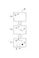
図3はオートシャッター機能の説明図であり、図3で符号35は被写体、符号36はブレているスルー画像、符号37は手ブレの方向を示す矢印、符号38は静止したスルー画像、符号39はブレなしとして撮影された静止画像を示す。
デジタルカメラ1で図3(a)に示すような被写体35を撮影しようとする場合、図3(b)や図3(c)に示すように手ブレや動体ブレによりスルー画像36がブレるが、手ブレがある場合は矢印37により警告表示がなされるので、撮影者はカメラを持ち直して手ブレを抑制する。撮影者が手ブレを抑制している間に図3(d)に示すように被写体35の動きが略停止すれば静止したスルー画像38が表示されブレがなくなるので、ブレが所定の閾値以下の場合にオートシャッターにより自動的に撮影を行ってブレのない静止画像39を撮影する(図3(e))。FIG. 3 is an explanatory diagram of the auto shutter function. In FIG. 3,
When the
図4はオートシャッターモードにおけるデジタルカメラ1の動作概要を示すフローチャートであり、このフローチャートはデジタルカメラ1に本願発明のオートシャッターの各機能を実現させるためのプログラムを説明するためのものである。
以下に示す処理は基本的に制御部22が予めフラッシュメモリ等のプログラムメモリに記憶されたプログラムに従って実行する例で説明するが、全ての機能をプログラムメモリに格納する必要はなく、必要に応じて、その一部若しくは全部をネットワークを介して受信して実現するようにしてもよい。以下、図1〜図4に基いて説明する。FIG. 4 is a flowchart showing an outline of the operation of the
The processing shown below is basically explained by an example in which the
オートシャッターモードにおいて、制御部22はその時点のズーム値に対応した焦点距離でAE処理を実行し、CCD13から画像データを得ると共に自動ホワイトバランス(AWB)処理により光源の色に対応したホワイトバランスになるようにカラープロセス回路18で調整を施した上でDMAコントローラ19及びDRAMインターフェイス(I/F)20を介してDRAM21にDMA転送すると共に、VRAM24をCCD13からの画像データを間引いたビデオスルー画像データで書き換えて表示部26の液晶モニタ画面4にスルー画像を表示する(ステップS1)。 In the auto shutter mode, the
手ブレ検出部32は、デジタルカメラ1のブレを検出して検出信号(デジタル信号)を所定時間間隔で制御部22に送出するので、制御部22は手ブレ検出部32から手ブレ検出信号を受け取ると、受け取った検出信号を基に手ブレ量を取得して(ステップS2)、手ブレ量と所定の閾値とを比較して手ブレ量が閾値以上の場合にはステップS4に進み、手ブレ量が閾値未満の場合にはステップS5に進む(ステップS3)。 The camera
手ブレ量が閾値以上の場合には手ブレ量に比例した大きさのマークを生成してVRAMコントローラ23を介してデジタルビデオエンコーダ25に与えビデオ信号を生成させて表示部26に出力させ、液晶モニタ画面4に表示させて手ブレが生じていることを撮影者に知らせてステップS1に戻る。これにより、撮影者にカメラを手ブレが生じないように保持し直すようにさせる。なお、手ブレ検出部32が手ブレ量の他に手ブレ方向を検出する装置からなるようにした場合は、図3に示したようなブレ量と方向を示す矢印37を表示することができる(ステップS4)。 When the amount of camera shake is equal to or greater than the threshold value, a mark having a size proportional to the amount of camera shake is generated, applied to the
手ブレ量が閾値未満のとき、制御部22は所定のフォーカスエリアにピントが合うように合焦(AF)処理を行い(ステップS5)、合焦処理が終わるまでステップS1に戻って上記ステップS1〜S5の動作を繰り返し、合焦処理が終わると合焦位置をロックしてステップS7に進む(ステップS6)。 When the amount of camera shake is less than the threshold value, the
ブレ検出部31は、DRAM21に直前に取込まれた画像Gzと今回取込まれた画像Gkの比較対象領域における動きベクトルを取得し、差分ΔG(又は差分に応じた数値を表すデジタル信号)を制御部22に出力するので、制御部22は受け取った動きベクトルの差分を取得し(ステップS7)、ブレ検出部31から受け取った動きベクトルの差分Δが所定の閾値δ以上か否かを調べ、動きベクトルの差分Δが所定の閾値δ未満の場合はブレ(手ブレ、動体ブレ)なしとしてステップS9に進み、差分Δが所定の閾値δ以上の場合はブレありとしてステップS7に戻る。なお、図示していないがステップS7とこの判断ステップを繰り返している間にもスルー画像は表示される(ステップS8)。 The
ブレなしとされた場合は、その時点で撮影処理(つまり、CCD13から取込んでいる1画面分の画像データのDRAM21へのDMA転送の終了後、直ちにCCD13からのDRAM21への経路を停止するか、あるいはスルー画像取得時とは異なる本撮影時のCCD駆動方式への切替)を実行してシャッター擬似音を出力すると共に(ステップS9)、取込んだ画像データをVRAMコントローラ23を介してVRAM24の内容を書き換えて表示部26の液晶モニタ画面4に静止画像を表示する(ステップS10)。 If there is no blurring, at that point in time, the path from the CCD 13 to the
また、上記静止画像表示と並行して上記ステップS9でDRAM21に記憶した画像データに画像圧縮処理を施した後、この圧縮画像データ(画像ファイル)を保存メモリ28に記録する(ステップS11)。 In parallel with the still image display, the image data stored in the
上記図4のフローチャートに示す動作により、デジタルカメラ1は手ブレや被写体の動きによるブレのない画像をシャッター操作なしで(つまり、オートシャッターで)撮影することができるので、シャッター操作時に生じやすいシャッターキー8の押し下げ等によるブレや撮影者が被写体の静止を認識してからシャッターキー8を押すまでのわずかな時間の間に起きる被写体の動きによるブレも生じない。
また、撮影者にとっては手ブレを生じないようにカメラを構えているだけで被写体ブレのない画像を撮影できる。更に、手ブレの有無や大きさ等をマークで示すので手ブレの有無を認識しやすい。The operation shown in the flowchart of FIG. 4 allows the
In addition, the photographer can shoot an image free from subject blur simply by holding the camera so as not to cause camera shake. Furthermore, since the presence or absence, size, etc. of camera shake are indicated by marks, it is easy to recognize the presence or absence of camera shake.
なお、上記図4のフローチャートでは「手ブレ量の取得〜手ブレ量のマーク表示」動作をステップS3〜S5で行うようにしたが、「手ブレ量の取得〜手ブレ量のマーク表示」動作をステップS5とステップS6の自動合焦処理中に行うようにしてもよく、ステップS6とステップS7の間で行うようにしてもよい。また、「手ブレ量の取得〜手ブレ量のマーク表示」動作は必須ではない。また、「マーク表示」に変えて警告音等を出力するようにしてもよい。 In the flowchart of FIG. 4, the “camera shake amount acquisition—camera shake amount mark display” operation is performed in steps S3 to S5, but the “camera shake amount acquisition—camera shake amount mark display” operation is performed. May be performed during the automatic focusing process of steps S5 and S6, or may be performed between steps S6 and S7. Further, the operation of “obtaining the amount of camera shake to displaying the mark of the amount of camera shake” is not essential. Further, a warning sound or the like may be output instead of “mark display”.
<変形例1>
上記図4のフローチャートでは、ステップS8でブレ量が所定の閾値未満の場合に直ちにオートシャッターによる撮影処理を行うようにしたが、撮影者に構図等の確認の余裕を与えるためしばらく(例えば、2秒ほど)してからオートシャッターによる撮影処理を行うようにしてもよい。<
In the flowchart of FIG. 4 above, when the amount of blur is less than the predetermined threshold value in step S8, the shooting process using the auto shutter is immediately performed. However, in order to give the photographer a margin for checking the composition or the like (for example, 2 It is also possible to perform shooting processing using an auto shutter after about a second).
図5は図4のフローチャートの変形例を示す図であり、図4のフローチャートのステップS9とS10を図示のように置き換えてブレなしとなった場合の構図確認を容易とした例である。 FIG. 5 is a diagram showing a modified example of the flowchart of FIG. 4. In this example, steps S9 and S10 in the flowchart of FIG.
図4のフローチャートのステップS8で、動きベクトルの差分Δが所定の閾値δ未満の場合に、制御部22は、RAMの所定アリアに確保した撮影待ち時間カウンタTの値を0に設定してから、撮影時間待ちカウンタのカウントを開始すると共に(ステップS9−1)、液晶モニタ画面4にスルー画像を表示する(ステップS9−2)。 When the motion vector difference Δ is less than the predetermined threshold δ in step S8 of the flowchart of FIG. 4, the
制御部22はブレ検出部31から動きベクトルの差分Δを取得し(ステップS9−3)、ベクトルの差分Δが所定の閾値δ以上か否かを調べ、動きベクトルの差分Δが所定の閾値δ未満の場合はブレ(手ブレ、動体ブレ)なしとしてステップS10−1に進み、差分Δが所定の閾値δ以上の場合はブレありとして合焦位置のロックを解除してステップS1に戻る(ステップS9−4)。 The
制御部22は撮影待ち時間カウンタTの値を調べ、撮影待ち時間カウンタTの値が所定時間(この例では2秒)になるとステップS10−2に進み、所定値未満の場合はステップS9−2に戻る(ステップS10−1)。 The
制御部22は、その時点で撮影処理(つまり、CCD13から取込んでいる1画面分の画像データのDRAM21へのDMA転送の終了後、直ちにCCD13からのDRAM21への経路を停止するか、あるいはスルー画像取得時とは異なる本撮影時のCCD駆動方式への切替)を実行してシャッター擬似音を出力して図4のフローチャートのステップS11に進む(S10−2)。 At that time, the
上記図5に示した変形例の動作により、電子カメラがブレなしと判定してからオートシャッター撮影までに少し間があるので、撮影者は表示されているスルー画像によりオートシャッターによる撮影処理の間に画像の構図を確認できる。また、撮影待ち時間中に再びブレの有無を判定しているので、撮影待ち時間の間にカメラや被写体が動いた場合には時間のカウントはキャンセルされオートシャッターによる撮影を行うことなくスルー画像表示に戻るので、ブレた画像が撮影されることはない。また、静止画表示された画像の構図等が不満足の場合にカメラを動かせばその画像はオートシャッターによる撮影を行うことなくキャンセルされスルー画像表示に戻るので、撮影者の所望の構図のブレのない画像を撮影できる。 With the operation of the modified example shown in FIG. 5 above, there is a short period between the time when the electronic camera determines that there is no blurring and the time when the auto shutter is shot. You can check the composition of the image. In addition, since the presence or absence of blurring is determined again during the shooting waiting time, if the camera or subject moves during the shooting waiting time, the time count is canceled and the through image is displayed without shooting with the auto shutter. Since the process returns to, a blurred image is never taken. Also, if the composition of the image displayed on the still image is unsatisfactory, if the camera is moved, the image is canceled without shooting with the auto shutter and the display returns to the through image display, so that there is no blur in the photographer's desired composition. You can take an image.
<変形例2>
動いている被写体の撮影を行う場合に被写体がカメラ視野内の特定のエリア(例えば、中央付近)で静止したときに撮影したい場合がある。
本実施例では撮影者が設定したエリア内に被写体が静止したときにデジタルカメラ1が自動的に撮影処理(オートシャッター)を行う例について図1〜図4、図6、図7に基づいて説明する。<
When shooting a moving subject, there are cases where it is desired to take a shot when the subject is stationary in a specific area (for example, near the center) within the camera field of view.
In this embodiment, an example in which the
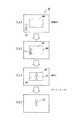
図6はオートシャッターエリア設定の説明図であり、符号61はカーソルの始点であり、SETキー6の操作により確定され色(例えば青色)表示される(図6(a))。符号62はカーソルキー5の操作により移動中のカーソルであり(図6(b))、符号63はSETキー6の操作により確定された終点であり、始点とは異なる色(例えば緑)で表示される。また、符号64はカーソルの始点61と終点63を結ぶ線分を対角線とする矩形枠(以下、オートシャッタエリア枠)であり、矩形枠内を示す符号65は被写体が静止したときにオートシャッター撮影がされるエリア(以下、オートシャッターエリア)である(図6(c))。 FIG. 6 is an explanatory diagram of the auto shutter area setting.
後述する図8のステップS0で上述したようにカーソルキー5及びSETキー6の操作により始点61と終点63を指定するとオートシャッターエリア枠64に囲まれたオートシャッターエリア65が設定され、画面上にオートシャッターエリア枠64が表示される。 When the
図7はオートシャッターエリア65におけるオートシャッター撮影の説明図であり、符号71は移動中の被写体であり符号72はオートシャッターエリア65で静止したブレのない被写体を示し、符号73はオートシャッターにより撮影された被写体画像を示す。 FIG. 7 is an explanatory diagram of auto-shutter shooting in the auto-
図7(a)は移動中の被写体画像71がスルー表示されているがオートシャッターエリア枠64とは離れている状態を示し、図7(b)は被写体71がオートシャッターエリア枠64に差し掛かった状態、若しくは撮影者が被写体71をオートシャッターエリア枠64内に収めようとカメラを動かした状態を示し、図7(c)はオートシャッターエリア65内で静止した被写体72を示し、図7(d)は被写体75がブレていないことが確認され、オートシャッター撮影された被写体の静止画像73を示す。 FIG. 7A shows a state in which the moving
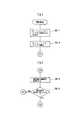
図8は図4のフローチャートの変形例を示す図であり、図4のフローチャートのステップS1の前段に図示のようにステップS0−1、S0−2を加え、ステップS8とS9の間にステップS8−2とS8−3を加えた例である。
つまり、図4のステップS1の前段に図8(a)に示すように、「図6の例に示したように、オートシャッターモードで撮影者がカーソルキー5及びSETキー6を操作して液晶モニタ画面4上の任意の位置で始点及び終点を指定すると、制御部22はオートシャッターエリア枠を液晶モニタ画面4上に表示する」ステップS0−1と、「オートシャッターエリアの4隅の座標をRAMの所定エリアに保持(記憶)する」ステップS0−2とを加え、更に、図8(b)に示すように、「被写体の輪郭を取得する」ステップS8−2と、「上記ステップS8−2で取得した被写体の輪郭の座標と上記ステップS0−2で設定したオートシャッターエリア枠の座標から被写体がオートシャッターエリア枠内に完全に収まったか否かを判定し、被写体がオートシャッターエリア枠内に完全に収まっている場合はステップS9に進み、そうでない場合はステップS7に戻る」ステップS8−3を加えるようにする。
なお、上記ステップS8−2における被写体の輪郭取得は公知の方法によればよく、例えば、輪郭抽出によって被写体の輪郭を抽出する場合はデジタルカメラ1に公知の輪郭抽出方法で輪郭抽出を行う方法輪郭抽出部を設けてもよい。FIG. 8 is a diagram showing a modification of the flowchart of FIG. 4. Steps S 0-1 and S 0-2 are added to the preceding stage of
That is, as shown in FIG. 8A in the previous stage of step S1 in FIG. 4, “as shown in the example of FIG. 6, the photographer operates the
Note that the subject contour acquisition in step S8-2 may be performed by a known method. For example, when the contour of the subject is extracted by contour extraction, the contour of the
このように構成することにより、図4のステップS1において撮影者が指定されたオートシャッターエリア枠がスルー画像と共に液晶モニタ画面4に表示されるので、撮影者がカメラを動かして撮影したい被写体がオートシャッターエリア枠内に収まるようにするか被写体がオートシャッターエリア枠内に収まるのを待つようにすれば、図4のステップS2、S3で手ブレ状態が判定され、ステップS4でカメラを構え直して手ブレを抑制するとステップS5で自動合焦が行われ、ステップS7、S8により被写体のブレの有無が判定され、被写体のブレがないと判定されると更に被写体がオートシャッターエリア枠内に収まっているか否かをステップS8−2、S8−3で調べ、被写体がオートシャッターエリア枠内に完全に収まっている場合にステップS9でオートシャッター撮影が行われる。 With this configuration, the auto shutter area frame designated by the photographer in step S1 in FIG. 4 is displayed on the liquid
つまり、従来、シャッター操作で被写体を撮影する場合はシャッターキーを押す指の反応次第でせっかく被写体が静止してもシャッターチャンスを逃す場合があったが、上記本発明の構成により、撮影者はオートシャッターエリア枠内に被写体を収めるようにしていれば移動する被写体がオートシャッターエリア枠で静止したときに自動撮影がなされるので、シャッターチャンスを逃すようなことがない。 In other words, conventionally, when shooting a subject by shutter operation, there was a case where the photographer missed a photo opportunity even if the subject was stationary depending on the reaction of the finger pressing the shutter key. If the subject is placed in the shutter area frame, automatic shooting is performed when the moving subject stops in the auto shutter area frame, so that a photo opportunity is not missed.
<変形例3>
静止した状態を判定する場合、ジャイロ方式にしろ動きベクトル方式にしろある閾値を設けて判断しているが(図4のステップS3、S8、図5のステップS9−4参照)、その閾値をカメラのシャッター速度に合わせて変化させるようにしてもよい。例えば、明るい状況ではAE制御によりシャッター速度が速くなるため手ブレを気にしなくてもよいので閾値を甘く設定し、暗い状況ではAE制御によりシャッター速度が遅くなり、手ブレの可能性が高くなるので閾値を厳しく設定するようにしてもよい。<
When determining a stationary state, a threshold value is determined by setting a gyro method or a motion vector method (see steps S3 and S8 in FIG. 4 and step S9-4 in FIG. 5). It may be changed in accordance with the shutter speed. For example, in bright situations, the shutter speed becomes faster due to AE control, so there is no need to worry about camera shake, so the threshold is set softer. In dark situations, the shutter speed becomes slower due to AE control, and the possibility of camera shake increases. Therefore, the threshold value may be set strictly.
図9はブレ判定用閾値設定テーブルの構成例を示す図であり、ブレ判定用閾値設定テーブル90はシャッタースピードtが速くなるほどブレ判定用閾値γを大きくするようにシャッタースピードt1、t2、・・・、tnとブレ判定用閾値γ1、γ2、・・・、γnを対応付けてプログラム格納メモリに格納されているものとする。 FIG. 9 is a diagram showing a configuration example of the blur determination threshold value setting table. The blur determination threshold value setting table 90 has shutter speeds t1, t2,... To increase the blur determination threshold value γ as the shutter speed t increases. It is assumed that tn and blur determination threshold values γ1, γ2,..., Γn are stored in the program storage memory in association with each other.
図10は、図4のフローチャートの変形例を示す図であり、図4のフローチャートのステップS8を図示のように、「制御部22は上記ステップS1で取込まれる被写体像の光量からシャッタースピードを決定し、図9に示したようなブレ判定用閾値設定テーブル90から決定されたシャッタースピードに対応付けられたブレ閾値を取り出して画像のブレ判定用の閾値とする」ステップS8−1と、「上記ステップS7で取得した画像のブレ量と上記ステップS8−1で取得した閾値とを比較して画像のブレ量が閾値以上の場合にはステップS7に戻り、手ブレ量が閾値未満の場合にはステップS9に進む」ステップS8−2に置き換える。 FIG. 10 is a diagram showing a modification of the flowchart of FIG. 4. As shown in step S8 of the flowchart of FIG. 4, “the
ブレを最小限に押さえても必ずしも思い通りのシャッターチャンスで撮影できるとういわけではないが、上記図10のフローチャートに示したように画像のブレ判定用閾値を自動変更可能にすることによって、可能な範囲でシャッターチャンスを生かした撮影ができるようにしながらも、画像のブレの危険度が増すような状況では画像のブレ防止を優先させるような自動制御ができる。 Although it is not always possible to shoot with the desired shutter chance even if blurring is minimized, it is possible by automatically changing the blurring determination threshold value of the image as shown in the flowchart of FIG. While it is possible to take a picture by taking advantage of the shutter chance in the range, automatic control can be performed to give priority to prevention of image blur in a situation where the risk of image blur increases.
上記実施形態及び各変形例の説明では電子カメラとしてデジタルカメラを例としたが、電子カメラという語は、デジタルカメラ等のほか、カメラ付き携帯電話機や撮像部を有する情報機器などにも適用し得るものである。 In the description of the embodiment and each modification, a digital camera is used as an example of an electronic camera. However, the term electronic camera can be applied to a digital camera and the like, an information device having a camera-equipped mobile phone, and an imaging unit. Is.
以上、本発明のいくつかの実施例について説明したが本発明は上記各実施例に限定されるものではなく、種々の変形実施が可能であることはいうまでもない。 As mentioned above, although several Example of this invention was described, it cannot be overemphasized that this invention is not limited to said each Example, A various deformation | transformation implementation is possible.
1 デジタルカメラ(電子カメラ)
5 カーソルキー(エリア指定手段)
6 SETキー(エリア指定手段)
22 制御部(第1の判断手段、撮影制御手段、比較手段、第2の判断手段、枠線表示手段、シャッタースピード取得手段)
26 表示部(枠線表示手段)
31 ブレ検出部(ブレ検出手段、第2のブレ検出手段)
32 手ブレ検出部(ブレ検出手段、第1のブレ検出手段)
35 被写体
90 ブレ用閾値設定テーブル(閾値取得手段)1 Digital camera (electronic camera)
5 Cursor keys (Area designation means)
6 SET key (area designation means)
22 Control unit (first determination means, photographing control means, comparison means, second determination means, frame line display means, shutter speed acquisition means)
26 Display section (frame line display means)
31 Shake detection unit (blur detection means, second shake detection means)
32 Camera shake detection unit (blur detection means, first shake detection means)
35 subject 90 blur threshold setting table (threshold acquisition means)
Claims (9)
Translated fromJapanese前記撮像手段によって取り込まれる画像に基づき、画像のブレを検出するブレ検出手段と、
前記ブレ検出手段によって検出される画像のブレが所定の閾値未満であるか否かを判断する第1の判断手段と、
前記第1の判断手段により所定の閾値未満であると判断された場合に、撮影処理を実行する撮影制御手段と、
を備えたことを特徴とする電子カメラ。Imaging means for photographing a subject to obtain a photographed image;
Based on the image captured by the imaging means, a blur detection means for detecting blur of the image;
First determination means for determining whether or not the blur of the image detected by the blur detection means is less than a predetermined threshold;
An imaging control unit that executes an imaging process when the first determination unit determines that it is less than a predetermined threshold;
An electronic camera characterized by comprising:
前記ブレ検出手段によって検出される画像のブレを所定の閾値と比較する比較手段を含み、この比較手段による比較結果に基づき、画像のブレが所定の閾値未満であるか否かを判断する、
ことを特徴とする請求項1記載の電子カメラ。The first determination means includes
A comparison unit that compares image blur detected by the blur detection unit with a predetermined threshold, and based on a comparison result by the comparison unit, determines whether the image blur is less than a predetermined threshold;
The electronic camera according to claim 1.
前記比較手段は、前記第1のブレ検出手段によって検出される電子カメラ本体のブレを第1の閾値と比較する第1の比較手段と、前記第2のブレ検出手段によって検出される画像のブレを第2の閾値と比較する第2の比較手段とからなり、
前記第2のブレ検出手段は、前記第1の比較手段による比較結果が第1の閾値未満のときに前記撮像手段によって取り込まれる画像の対象領域におけるブレを検出し、
前記撮影制御手段は、前記第2の比較手段による比較結果が第2の閾値未満のときに撮影処理を実行する、
ことを特徴とする請求項1又は2記載の電子カメラ。The blur detection unit includes a first blur detection unit that detects a blur of the electronic camera body, and a second blur detection unit that detects a blur of an image.
The comparison unit includes a first comparison unit that compares a blur of the electronic camera body detected by the first blur detection unit with a first threshold value, and a blur of an image detected by the second blur detection unit. And a second comparison means for comparing the value with a second threshold value,
The second blur detection unit detects a blur in a target region of an image captured by the imaging unit when a comparison result by the first comparison unit is less than a first threshold;
The imaging control means executes imaging processing when the comparison result by the second comparison means is less than a second threshold;
The electronic camera according to claim 1 or 2, characterized in that
前記撮影制御手段は、前記経過時間計測手段により所定の経過時間が計測されたとき撮影処理を実行する、ことを特徴とする請求項1乃至3の何れかに記載の電子カメラ。Furthermore, it comprises an elapsed time measuring means for measuring an elapsed time from when it is determined by the first determination means to be less than a predetermined threshold,
The electronic camera according to claim 1, wherein the photographing control unit executes a photographing process when a predetermined elapsed time is measured by the elapsed time measuring unit.
前記撮影制御手段は、
前記第1の判断手段により所定の閾値未満であると判断され、且つ前記第2の判断手段により所定のエリア内に被写体像が収まっていると判断された場合に、撮影処理を実行することを特徴とする請求項1乃至4の何れかに記載の電子カメラ。Further, the image processing apparatus further comprises second determination means for determining whether or not the subject image is within a predetermined area in the image captured by the imaging means.
The photographing control means includes
When the first determination unit determines that the image is less than a predetermined threshold value and the second determination unit determines that the subject image is within a predetermined area, the photographing process is executed. The electronic camera according to claim 1, wherein the electronic camera is characterized in that:
前記第2の判断手段は、前記撮像手段によって取り込まれる画像中の、前記エリア指定手段により指定された任意のエリア内に被写体像が収まっているか否かを判断する、
ことを特徴とする請求項5記載の電子カメラ。Furthermore, an area designating unit for designating an arbitrary area in the image captured by the imaging unit is provided.
The second determination means determines whether or not the subject image is within an arbitrary area designated by the area designation means in the image captured by the imaging means;
The electronic camera according to claim 5.
前記シャッタースピード取得手段によって取得されたシャッタースピードに応じた閾値を取得する閾値取得手段とを備え、
前記第1の判断手段は、前記ブレ検出手段によって検出される画像のブレが、前記閾値取得手段により取得された閾値未満であるか否かを判断すること、
を特徴とする請求項1乃至7のいずれかに記載の電子カメラ。Furthermore, shutter speed acquisition means for acquiring the shutter speed based on the brightness,
Threshold acquisition means for acquiring a threshold according to the shutter speed acquired by the shutter speed acquisition means,
The first determination means determines whether or not the blur of the image detected by the blur detection means is less than the threshold acquired by the threshold acquisition means;
The electronic camera according to claim 1, wherein:
被写体を撮影して撮影画像を得る機能と、
得られた撮影画像に基づき、画像のブレを検出する機能と、
検出された画像のブレが所定の閾値未満であるか否かを判断する機能と、
所定の閾値未満であると判断された場合に撮影処理を行う機能と、
を実行させるプログラム。To the computer of the electronic camera,
A function to capture a photographed image of a subject,
A function for detecting image blur based on the obtained captured image;
A function of determining whether or not the detected image blur is less than a predetermined threshold;
A function of performing a photographing process when it is determined that it is less than a predetermined threshold;
A program that executes
Priority Applications (1)
| Application Number | Priority Date | Filing Date | Title |
|---|---|---|---|
| JP2004364022AJP4999268B2 (en) | 2004-12-16 | 2004-12-16 | Electronic camera and program |
Applications Claiming Priority (1)
| Application Number | Priority Date | Filing Date | Title |
|---|---|---|---|
| JP2004364022AJP4999268B2 (en) | 2004-12-16 | 2004-12-16 | Electronic camera and program |
Related Child Applications (1)
| Application Number | Title | Priority Date | Filing Date |
|---|---|---|---|
| JP2010115960ADivisionJP4962597B2 (en) | 2010-05-20 | 2010-05-20 | Electronic camera and program |
Publications (2)
| Publication Number | Publication Date |
|---|---|
| JP2006174105Atrue JP2006174105A (en) | 2006-06-29 |
| JP4999268B2 JP4999268B2 (en) | 2012-08-15 |
Family
ID=36674377
Family Applications (1)
| Application Number | Title | Priority Date | Filing Date |
|---|---|---|---|
| JP2004364022AExpired - Fee RelatedJP4999268B2 (en) | 2004-12-16 | 2004-12-16 | Electronic camera and program |
Country Status (1)
| Country | Link |
|---|---|
| JP (1) | JP4999268B2 (en) |
Cited By (41)
| Publication number | Priority date | Publication date | Assignee | Title |
|---|---|---|---|---|
| JP2008103998A (en)* | 2006-10-19 | 2008-05-01 | Matsushita Electric Ind Co Ltd | Digital camera, electronic device equipped with digital camera, imaging method of digital camera, and storage medium storing digital camera program |
| JP2008288975A (en)* | 2007-05-18 | 2008-11-27 | Casio Comput Co Ltd | Imaging apparatus, imaging method, and imaging program |
| EP2076023A2 (en) | 2007-12-28 | 2009-07-01 | Casio Computer Co., Ltd. | Image capturing device and program |
| JP2009207119A (en)* | 2007-12-28 | 2009-09-10 | Casio Comput Co Ltd | Imaging apparatus and program |
| JP2009246962A (en)* | 2008-03-28 | 2009-10-22 | Fuji Xerox Co Ltd | Camera system, method performed using the camera system, and program |
| JP2010045587A (en)* | 2008-08-12 | 2010-02-25 | Sony Ericsson Mobile Communications Ab | Camera apparatus, image photography support device, image photography support method, and image photography support program |
| JP2010130327A (en)* | 2008-11-27 | 2010-06-10 | Casio Computer Co Ltd | Imaging device and program |
| CN101562697B (en)* | 2008-04-17 | 2011-11-09 | 鸿富锦精密工业(深圳)有限公司 | Camera head and camera shooting method |
| JP2012165407A (en)* | 2007-12-28 | 2012-08-30 | Casio Comput Co Ltd | Imaging apparatus and program |
| CN102883102A (en)* | 2011-07-15 | 2013-01-16 | 卡西欧计算机株式会社 | Image processing apparatus, image processing method, and storage medium |
| US8465415B2 (en) | 2009-07-23 | 2013-06-18 | Olympus Corporation | Endoscope apparatus and measurement method |
| WO2013084450A3 (en)* | 2011-12-06 | 2013-08-08 | Sony Corporation | Information processing terminal, information processing method, and program |
| JP2014011628A (en)* | 2012-06-29 | 2014-01-20 | Xacti Corp | Image pickup device |
| JPWO2013069048A1 (en)* | 2011-11-07 | 2015-04-02 | 株式会社ソニー・コンピュータエンタテインメント | Image generating apparatus and image generating method |
| JP2015179967A (en)* | 2014-03-19 | 2015-10-08 | カシオ計算機株式会社 | Imaging apparatus, imaging method, and program |
| US9560274B2 (en) | 2011-11-07 | 2017-01-31 | Sony Corporation | Image generation apparatus and image generation method |
| US9729788B2 (en) | 2011-11-07 | 2017-08-08 | Sony Corporation | Image generation apparatus and image generation method |
| US10284776B2 (en) | 2011-11-07 | 2019-05-07 | Sony Interactive Entertainment Inc. | Image generation apparatus and image generation method |
| US10713629B1 (en) | 2007-09-28 | 2020-07-14 | United Services Automobile Association (Usaa) | Systems and methods for digital signature detection |
| US10810561B1 (en) | 2007-10-23 | 2020-10-20 | United Services Automobile Association (Usaa) | Image processing |
| US10839358B1 (en) | 2008-02-07 | 2020-11-17 | United Services Automobile Association (Usaa) | Systems and methods for mobile deposit of negotiable instruments |
| US10848665B1 (en) | 2009-08-28 | 2020-11-24 | United Services Automobile Association (Usaa) | Computer systems for updating a record to reflect data contained in image of document automatically captured on a user's remote mobile phone displaying an alignment guide and using a downloaded app |
| US10896408B1 (en) | 2009-08-19 | 2021-01-19 | United Services Automobile Association (Usaa) | Apparatuses, methods and systems for a publishing and subscribing platform of depositing negotiable instruments |
| US10956728B1 (en) | 2009-03-04 | 2021-03-23 | United Services Automobile Association (Usaa) | Systems and methods of check processing with background removal |
| US11023719B1 (en) | 2006-10-31 | 2021-06-01 | United Services Automobile Association (Usaa) | Digital camera processing system |
| US11030752B1 (en) | 2018-04-27 | 2021-06-08 | United Services Automobile Association (Usaa) | System, computing device, and method for document detection |
| US11062130B1 (en) | 2009-02-18 | 2021-07-13 | United Services Automobile Association (Usaa) | Systems and methods of check detection |
| US11062283B1 (en) | 2012-01-05 | 2021-07-13 | United Services Automobile Association (Usaa) | System and method for storefront bank deposits |
| US11068976B1 (en) | 2010-06-08 | 2021-07-20 | United Services Automobile Association (Usaa) | Financial document image capture deposit method, system, and computer-readable |
| US11138578B1 (en) | 2013-09-09 | 2021-10-05 | United Services Automobile Association (Usaa) | Systems and methods for remote deposit of currency |
| US11144753B1 (en) | 2013-10-17 | 2021-10-12 | United Services Automobile Association (Usaa) | Character count determination for a digital image |
| US11182753B1 (en) | 2006-10-31 | 2021-11-23 | United Services Automobile Association (Usaa) | Systems and methods for remote deposit of checks |
| US11200550B1 (en) | 2003-10-30 | 2021-12-14 | United Services Automobile Association (Usaa) | Wireless electronic check deposit scanning and cashing machine with web-based online account cash management computer application system |
| US11216884B1 (en) | 2008-09-08 | 2022-01-04 | United Services Automobile Association (Usaa) | Systems and methods for live video financial deposit |
| US11321678B1 (en) | 2009-08-21 | 2022-05-03 | United Services Automobile Association (Usaa) | Systems and methods for processing an image of a check during mobile deposit |
| JP2022139871A (en)* | 2021-03-12 | 2022-09-26 | 大日本印刷株式会社 | shooting system |
| US20230036808A1 (en)* | 2021-08-02 | 2023-02-02 | Intuit Inc. | Vertex change detection for enhanced document capture |
| US11900755B1 (en) | 2020-11-30 | 2024-02-13 | United Services Automobile Association (Usaa) | System, computing device, and method for document detection and deposit processing |
| US12100257B2 (en) | 2018-11-26 | 2024-09-24 | Capital One Services, Llc | Systems and methods for visual verification |
| US12211095B1 (en) | 2024-03-01 | 2025-01-28 | United Services Automobile Association (Usaa) | System and method for mobile check deposit enabling auto-capture functionality via video frame processing |
| US12293600B2 (en) | 2019-06-07 | 2025-05-06 | Capital One Services, Llc | Automatic image capture system based on a determination and verification of a physical object size in a captured image |
Citations (5)
| Publication number | Priority date | Publication date | Assignee | Title |
|---|---|---|---|---|
| JPH05100288A (en)* | 1991-10-11 | 1993-04-23 | Minolta Camera Co Ltd | Camera with electric view finder |
| JPH10161168A (en)* | 1996-11-29 | 1998-06-19 | Minolta Co Ltd | Shake correcting device |
| JPH11317904A (en)* | 1998-05-01 | 1999-11-16 | Canon Inc | Imaging device and control method thereof |
| JP2002094839A (en)* | 2000-09-20 | 2002-03-29 | Matsushita Electric Ind Co Ltd | Electronic still camera |
| JP2006005662A (en)* | 2004-06-17 | 2006-01-05 | Nikon Corp | Electronic camera and electronic camera system |
- 2004
- 2004-12-16JPJP2004364022Apatent/JP4999268B2/ennot_activeExpired - Fee Related
Patent Citations (5)
| Publication number | Priority date | Publication date | Assignee | Title |
|---|---|---|---|---|
| JPH05100288A (en)* | 1991-10-11 | 1993-04-23 | Minolta Camera Co Ltd | Camera with electric view finder |
| JPH10161168A (en)* | 1996-11-29 | 1998-06-19 | Minolta Co Ltd | Shake correcting device |
| JPH11317904A (en)* | 1998-05-01 | 1999-11-16 | Canon Inc | Imaging device and control method thereof |
| JP2002094839A (en)* | 2000-09-20 | 2002-03-29 | Matsushita Electric Ind Co Ltd | Electronic still camera |
| JP2006005662A (en)* | 2004-06-17 | 2006-01-05 | Nikon Corp | Electronic camera and electronic camera system |
Cited By (97)
| Publication number | Priority date | Publication date | Assignee | Title |
|---|---|---|---|---|
| US11200550B1 (en) | 2003-10-30 | 2021-12-14 | United Services Automobile Association (Usaa) | Wireless electronic check deposit scanning and cashing machine with web-based online account cash management computer application system |
| JP2008103998A (en)* | 2006-10-19 | 2008-05-01 | Matsushita Electric Ind Co Ltd | Digital camera, electronic device equipped with digital camera, imaging method of digital camera, and storage medium storing digital camera program |
| US11461743B1 (en) | 2006-10-31 | 2022-10-04 | United Services Automobile Association (Usaa) | Systems and methods for remote deposit of checks |
| US11544944B1 (en) | 2006-10-31 | 2023-01-03 | United Services Automobile Association (Usaa) | Digital camera processing system |
| US11023719B1 (en) | 2006-10-31 | 2021-06-01 | United Services Automobile Association (Usaa) | Digital camera processing system |
| US11182753B1 (en) | 2006-10-31 | 2021-11-23 | United Services Automobile Association (Usaa) | Systems and methods for remote deposit of checks |
| US11562332B1 (en) | 2006-10-31 | 2023-01-24 | United Services Automobile Association (Usaa) | Systems and methods for remote deposit of checks |
| US11625770B1 (en) | 2006-10-31 | 2023-04-11 | United Services Automobile Association (Usaa) | Digital camera processing system |
| US11488405B1 (en) | 2006-10-31 | 2022-11-01 | United Services Automobile Association (Usaa) | Systems and methods for remote deposit of checks |
| US11875314B1 (en) | 2006-10-31 | 2024-01-16 | United Services Automobile Association (Usaa) | Systems and methods for remote deposit of checks |
| JP2008288975A (en)* | 2007-05-18 | 2008-11-27 | Casio Comput Co Ltd | Imaging apparatus, imaging method, and imaging program |
| US8564674B2 (en) | 2007-05-18 | 2013-10-22 | Casio Computer Co., Ltd. | Image pickup apparatus equipped with function of detecting image shaking |
| US11328267B1 (en) | 2007-09-28 | 2022-05-10 | United Services Automobile Association (Usaa) | Systems and methods for digital signature detection |
| US10713629B1 (en) | 2007-09-28 | 2020-07-14 | United Services Automobile Association (Usaa) | Systems and methods for digital signature detection |
| US11392912B1 (en) | 2007-10-23 | 2022-07-19 | United Services Automobile Association (Usaa) | Image processing |
| US12175439B1 (en) | 2007-10-23 | 2024-12-24 | United Services Automobile Association (Usaa) | Image processing |
| US10810561B1 (en) | 2007-10-23 | 2020-10-20 | United Services Automobile Association (Usaa) | Image processing |
| US10915879B1 (en) | 2007-10-23 | 2021-02-09 | United Services Automobile Association (Usaa) | Image processing |
| EP2076023A3 (en)* | 2007-12-28 | 2012-08-22 | Casio Computer Co., Ltd. | Image capturing device and program |
| CN103873774B (en)* | 2007-12-28 | 2017-12-26 | 卡西欧计算机株式会社 | Camera, method for imaging and recording medium |
| US8786721B2 (en) | 2007-12-28 | 2014-07-22 | Casio Computer Co., Ltd. | Image capturing device |
| US8872934B2 (en) | 2007-12-28 | 2014-10-28 | Casio Computer Co., Ltd. | Image capturing device which inhibits incorrect detection of subject movement during automatic image capturing |
| EP2076023A2 (en) | 2007-12-28 | 2009-07-01 | Casio Computer Co., Ltd. | Image capturing device and program |
| TWI492618B (en)* | 2007-12-28 | 2015-07-11 | Casio Computer Co Ltd | Image pickup device and computer readable recording medium |
| EP2602990A2 (en) | 2007-12-28 | 2013-06-12 | Casio Computer Co., Ltd. | Image capturing device and program |
| JP2009159559A (en)* | 2007-12-28 | 2009-07-16 | Casio Comput Co Ltd | Imaging apparatus and program thereof |
| JP2012165407A (en)* | 2007-12-28 | 2012-08-30 | Casio Comput Co Ltd | Imaging apparatus and program |
| EP2602990A3 (en)* | 2007-12-28 | 2017-05-10 | Casio Computer Co., Ltd. | Image capturing device and program |
| JP2009207119A (en)* | 2007-12-28 | 2009-09-10 | Casio Comput Co Ltd | Imaging apparatus and program |
| US8723976B2 (en) | 2007-12-28 | 2014-05-13 | Casio Computer Co., Ltd. | Imaging device and storage medium |
| KR101013830B1 (en) | 2007-12-28 | 2011-02-14 | 가시오게산키 가부시키가이샤 | Recording medium recording the shooting device and program |
| US10839358B1 (en) | 2008-02-07 | 2020-11-17 | United Services Automobile Association (Usaa) | Systems and methods for mobile deposit of negotiable instruments |
| US11531973B1 (en) | 2008-02-07 | 2022-12-20 | United Services Automobile Association (Usaa) | Systems and methods for mobile deposit of negotiable instruments |
| US12229737B2 (en) | 2008-02-07 | 2025-02-18 | United Services Automobile Association (Usaa) | Systems and methods for mobile deposit of negotiable instruments |
| JP2009246962A (en)* | 2008-03-28 | 2009-10-22 | Fuji Xerox Co Ltd | Camera system, method performed using the camera system, and program |
| CN101562697B (en)* | 2008-04-17 | 2011-11-09 | 鸿富锦精密工业(深圳)有限公司 | Camera head and camera shooting method |
| JP2010045587A (en)* | 2008-08-12 | 2010-02-25 | Sony Ericsson Mobile Communications Ab | Camera apparatus, image photography support device, image photography support method, and image photography support program |
| US11216884B1 (en) | 2008-09-08 | 2022-01-04 | United Services Automobile Association (Usaa) | Systems and methods for live video financial deposit |
| JP2010130327A (en)* | 2008-11-27 | 2010-06-10 | Casio Computer Co Ltd | Imaging device and program |
| US11062130B1 (en) | 2009-02-18 | 2021-07-13 | United Services Automobile Association (Usaa) | Systems and methods of check detection |
| US11749007B1 (en) | 2009-02-18 | 2023-09-05 | United Services Automobile Association (Usaa) | Systems and methods of check detection |
| US11062131B1 (en) | 2009-02-18 | 2021-07-13 | United Services Automobile Association (Usaa) | Systems and methods of check detection |
| US10956728B1 (en) | 2009-03-04 | 2021-03-23 | United Services Automobile Association (Usaa) | Systems and methods of check processing with background removal |
| US11721117B1 (en) | 2009-03-04 | 2023-08-08 | United Services Automobile Association (Usaa) | Systems and methods of check processing with background removal |
| US8465415B2 (en) | 2009-07-23 | 2013-06-18 | Olympus Corporation | Endoscope apparatus and measurement method |
| US10896408B1 (en) | 2009-08-19 | 2021-01-19 | United Services Automobile Association (Usaa) | Apparatuses, methods and systems for a publishing and subscribing platform of depositing negotiable instruments |
| US12211015B1 (en) | 2009-08-19 | 2025-01-28 | United Services Automobile Association (Usaa) | Apparatuses, methods and systems for a publishing and subscribing platform of depositing negotiable instruments |
| US11222315B1 (en) | 2009-08-19 | 2022-01-11 | United Services Automobile Association (Usaa) | Apparatuses, methods and systems for a publishing and subscribing platform of depositing negotiable instruments |
| US11321678B1 (en) | 2009-08-21 | 2022-05-03 | United Services Automobile Association (Usaa) | Systems and methods for processing an image of a check during mobile deposit |
| US12159310B1 (en) | 2009-08-21 | 2024-12-03 | United Services Automobile Association (Usaa) | System and method for mobile check deposit enabling auto-capture functionality via video frame processing |
| US11373150B1 (en) | 2009-08-21 | 2022-06-28 | United Services Automobile Association (Usaa) | Systems and methods for monitoring and processing an image of a check during mobile deposit |
| US11373149B1 (en) | 2009-08-21 | 2022-06-28 | United Services Automobile Association (Usaa) | Systems and methods for monitoring and processing an image of a check during mobile deposit |
| US11341465B1 (en) | 2009-08-21 | 2022-05-24 | United Services Automobile Association (Usaa) | Systems and methods for image monitoring of check during mobile deposit |
| US11321679B1 (en) | 2009-08-21 | 2022-05-03 | United Services Automobile Association (Usaa) | Systems and methods for processing an image of a check during mobile deposit |
| US10855914B1 (en) | 2009-08-28 | 2020-12-01 | United Services Automobile Association (Usaa) | Computer systems for updating a record to reflect data contained in image of document automatically captured on a user's remote mobile phone displaying an alignment guide and using a downloaded app |
| US11064111B1 (en) | 2009-08-28 | 2021-07-13 | United Services Automobile Association (Usaa) | Systems and methods for alignment of check during mobile deposit |
| US10848665B1 (en) | 2009-08-28 | 2020-11-24 | United Services Automobile Association (Usaa) | Computer systems for updating a record to reflect data contained in image of document automatically captured on a user's remote mobile phone displaying an alignment guide and using a downloaded app |
| US12131300B1 (en) | 2009-08-28 | 2024-10-29 | United Services Automobile Association (Usaa) | Computer systems for updating a record to reflect data contained in image of document automatically captured on a user's remote mobile phone using a downloaded app with alignment guide |
| US11295377B1 (en) | 2010-06-08 | 2022-04-05 | United Services Automobile Association (Usaa) | Automatic remote deposit image preparation apparatuses, methods and systems |
| US11295378B1 (en) | 2010-06-08 | 2022-04-05 | United Services Automobile Association (Usaa) | Apparatuses, methods and systems for a video remote deposit capture platform |
| US11893628B1 (en) | 2010-06-08 | 2024-02-06 | United Services Automobile Association (Usaa) | Apparatuses, methods and systems for a video remote deposit capture platform |
| US11232517B1 (en) | 2010-06-08 | 2022-01-25 | United Services Automobile Association (Usaa) | Apparatuses, methods, and systems for remote deposit capture with enhanced image detection |
| US11068976B1 (en) | 2010-06-08 | 2021-07-20 | United Services Automobile Association (Usaa) | Financial document image capture deposit method, system, and computer-readable |
| US11915310B1 (en) | 2010-06-08 | 2024-02-27 | United Services Automobile Association (Usaa) | Apparatuses, methods and systems for a video remote deposit capture platform |
| US12400257B1 (en) | 2010-06-08 | 2025-08-26 | United Services Automobile Association (Usaa) | Automatic remote deposit image preparation apparatuses, methods and systems |
| JP2013026694A (en)* | 2011-07-15 | 2013-02-04 | Casio Comput Co Ltd | Image processing device, method and program |
| CN102883102A (en)* | 2011-07-15 | 2013-01-16 | 卡西欧计算机株式会社 | Image processing apparatus, image processing method, and storage medium |
| US9729788B2 (en) | 2011-11-07 | 2017-08-08 | Sony Corporation | Image generation apparatus and image generation method |
| JPWO2013069048A1 (en)* | 2011-11-07 | 2015-04-02 | 株式会社ソニー・コンピュータエンタテインメント | Image generating apparatus and image generating method |
| US9560274B2 (en) | 2011-11-07 | 2017-01-31 | Sony Corporation | Image generation apparatus and image generation method |
| US9894272B2 (en) | 2011-11-07 | 2018-02-13 | Sony Interactive Entertainment Inc. | Image generation apparatus and image generation method |
| US10284776B2 (en) | 2011-11-07 | 2019-05-07 | Sony Interactive Entertainment Inc. | Image generation apparatus and image generation method |
| WO2013084450A3 (en)* | 2011-12-06 | 2013-08-08 | Sony Corporation | Information processing terminal, information processing method, and program |
| US9357128B2 (en) | 2011-12-06 | 2016-05-31 | Sony Corporation | Information processing terminal, information processing method, and program |
| US11544682B1 (en) | 2012-01-05 | 2023-01-03 | United Services Automobile Association (Usaa) | System and method for storefront bank deposits |
| US11797960B1 (en) | 2012-01-05 | 2023-10-24 | United Services Automobile Association (Usaa) | System and method for storefront bank deposits |
| US11062283B1 (en) | 2012-01-05 | 2021-07-13 | United Services Automobile Association (Usaa) | System and method for storefront bank deposits |
| JP2014011628A (en)* | 2012-06-29 | 2014-01-20 | Xacti Corp | Image pickup device |
| US11138578B1 (en) | 2013-09-09 | 2021-10-05 | United Services Automobile Association (Usaa) | Systems and methods for remote deposit of currency |
| US12182781B1 (en) | 2013-09-09 | 2024-12-31 | United Services Automobile Association (Usaa) | Systems and methods for remote deposit of currency |
| US11144753B1 (en) | 2013-10-17 | 2021-10-12 | United Services Automobile Association (Usaa) | Character count determination for a digital image |
| US11694462B1 (en) | 2013-10-17 | 2023-07-04 | United Services Automobile Association (Usaa) | Character count determination for a digital image |
| US11281903B1 (en) | 2013-10-17 | 2022-03-22 | United Services Automobile Association (Usaa) | Character count determination for a digital image |
| JP2015179967A (en)* | 2014-03-19 | 2015-10-08 | カシオ計算機株式会社 | Imaging apparatus, imaging method, and program |
| US11676285B1 (en) | 2018-04-27 | 2023-06-13 | United Services Automobile Association (Usaa) | System, computing device, and method for document detection |
| US11030752B1 (en) | 2018-04-27 | 2021-06-08 | United Services Automobile Association (Usaa) | System, computing device, and method for document detection |
| US12100257B2 (en) | 2018-11-26 | 2024-09-24 | Capital One Services, Llc | Systems and methods for visual verification |
| US12293600B2 (en) | 2019-06-07 | 2025-05-06 | Capital One Services, Llc | Automatic image capture system based on a determination and verification of a physical object size in a captured image |
| US11900755B1 (en) | 2020-11-30 | 2024-02-13 | United Services Automobile Association (Usaa) | System, computing device, and method for document detection and deposit processing |
| US12260700B1 (en) | 2020-11-30 | 2025-03-25 | United Services Automobile Association (Usaa) | System, computing device, and method for document detection and deposit processing |
| JP2022139871A (en)* | 2021-03-12 | 2022-09-26 | 大日本印刷株式会社 | shooting system |
| EP4131929A1 (en)* | 2021-08-02 | 2023-02-08 | Intuit Inc. | Vertex change detection for enhanced document capture |
| US20230036808A1 (en)* | 2021-08-02 | 2023-02-02 | Intuit Inc. | Vertex change detection for enhanced document capture |
| US20240147047A1 (en)* | 2021-08-02 | 2024-05-02 | Intuit Inc. | Vertex change detection for enhanced document capture |
| AU2022204454B2 (en)* | 2021-08-02 | 2024-03-07 | Intuit Inc. | Vertex change detection for enhanced document capture |
| US11910079B2 (en)* | 2021-08-02 | 2024-02-20 | Intuit, Inc. | Vertex change detection for enhanced document capture |
| US12211095B1 (en) | 2024-03-01 | 2025-01-28 | United Services Automobile Association (Usaa) | System and method for mobile check deposit enabling auto-capture functionality via video frame processing |
Also Published As
| Publication number | Publication date |
|---|---|
| JP4999268B2 (en) | 2012-08-15 |
Similar Documents
| Publication | Publication Date | Title |
|---|---|---|
| JP4999268B2 (en) | Electronic camera and program | |
| TWI326553B (en) | Imaging apparatus, data extraction method, and data extraction program | |
| JP4645685B2 (en) | Camera, camera control program, and photographing method | |
| JP4872797B2 (en) | Imaging apparatus, imaging method, and imaging program | |
| TW200808044A (en) | Imaging apparatus and computer readable recording medium | |
| JP2005252657A (en) | Electronic still camera | |
| JP4605217B2 (en) | Imaging apparatus and program thereof | |
| JP2008079193A (en) | Digital camera | |
| JPH10224684A (en) | Information processing device | |
| JP4655708B2 (en) | Camera, camera shake state display method, and program | |
| JP4962597B2 (en) | Electronic camera and program | |
| JP4888829B2 (en) | Movie processing device, movie shooting device, and movie shooting program | |
| JP2008263478A (en) | Imaging device | |
| JP4828486B2 (en) | Digital camera, photographing method and photographing program | |
| JP4788172B2 (en) | Imaging apparatus and program | |
| JP2005278003A (en) | Image processing apparatus | |
| JP4045377B2 (en) | Information processing apparatus and recording medium | |
| JP2007228233A (en) | Imaging device | |
| JPH10224690A (en) | Information processing device and recording medium | |
| JP4054918B2 (en) | Imaging apparatus, photographing control method, and photographing control program | |
| JP2006145567A (en) | Camera, camera shake amount notification method, and program | |
| JP2008028956A (en) | Imaging device and method of generating image signal for object detection in imaging device | |
| JP4558108B2 (en) | Information processing apparatus, information processing method, and recording medium | |
| US20250054102A1 (en) | Image processing apparatus, image processing method, and image capture apparatus | |
| JP2011050107A (en) | Camera, camera control program, and imaging method |
Legal Events
| Date | Code | Title | Description |
|---|---|---|---|
| A621 | Written request for application examination | Free format text:JAPANESE INTERMEDIATE CODE: A621 Effective date:20071109 | |
| RD04 | Notification of resignation of power of attorney | Free format text:JAPANESE INTERMEDIATE CODE: A7424 Effective date:20080519 | |
| A131 | Notification of reasons for refusal | Free format text:JAPANESE INTERMEDIATE CODE: A131 Effective date:20091117 | |
| A521 | Request for written amendment filed | Free format text:JAPANESE INTERMEDIATE CODE: A523 Effective date:20100112 | |
| A02 | Decision of refusal | Free format text:JAPANESE INTERMEDIATE CODE: A02 Effective date:20100316 | |
| A521 | Request for written amendment filed | Free format text:JAPANESE INTERMEDIATE CODE: A523 Effective date:20100520 | |
| A911 | Transfer to examiner for re-examination before appeal (zenchi) | Free format text:JAPANESE INTERMEDIATE CODE: A911 Effective date:20100624 | |
| A912 | Re-examination (zenchi) completed and case transferred to appeal board | Free format text:JAPANESE INTERMEDIATE CODE: A912 Effective date:20100716 | |
| A521 | Request for written amendment filed | Free format text:JAPANESE INTERMEDIATE CODE: A523 Effective date:20120316 | |
| A01 | Written decision to grant a patent or to grant a registration (utility model) | Free format text:JAPANESE INTERMEDIATE CODE: A01 | |
| A61 | First payment of annual fees (during grant procedure) | Free format text:JAPANESE INTERMEDIATE CODE: A61 Effective date:20120515 | |
| R150 | Certificate of patent or registration of utility model | Free format text:JAPANESE INTERMEDIATE CODE: R150 Ref document number:4999268 Country of ref document:JP Free format text:JAPANESE INTERMEDIATE CODE: R150 | |
| FPAY | Renewal fee payment (event date is renewal date of database) | Free format text:PAYMENT UNTIL: 20150525 Year of fee payment:3 | |
| LAPS | Cancellation because of no payment of annual fees |