JP2006167403A - Bipolar electrosurgical instrument for sealing blood vessel - Google Patents
Bipolar electrosurgical instrument for sealing blood vesselDownload PDFInfo
- Publication number
- JP2006167403A JP2006167403AJP2004382576AJP2004382576AJP2006167403AJP 2006167403 AJP2006167403 AJP 2006167403AJP 2004382576 AJP2004382576 AJP 2004382576AJP 2004382576 AJP2004382576 AJP 2004382576AJP 2006167403 AJP2006167403 AJP 2006167403A
- Authority
- JP
- Japan
- Prior art keywords
- opposing
- bipolar electrosurgical
- tissue
- seal
- disposed
- Prior art date
- Legal status (The legal status is an assumption and is not a legal conclusion. Google has not performed a legal analysis and makes no representation as to the accuracy of the status listed.)
- Pending
Links
- 238000007789sealingMethods0.000titleclaimsdescription88
- 210000004204blood vesselAnatomy0.000titledescription20
- 238000001356surgical procedureMethods0.000claimsabstractdescription7
- 239000000463materialSubstances0.000claimsdescription24
- PXHVJJICTQNCMI-UHFFFAOYSA-NNickelChemical compound[Ni]PXHVJJICTQNCMI-UHFFFAOYSA-N0.000claimsdescription12
- 238000000576coating methodMethods0.000claimsdescription9
- 239000011248coating agentSubstances0.000claimsdescription8
- 238000000926separation methodMethods0.000claimsdescription8
- 239000000853adhesiveSubstances0.000claimsdescription5
- 230000001070adhesive effectEffects0.000claimsdescription5
- 239000000788chromium alloySubstances0.000claimsdescription4
- 229910000599Cr alloyInorganic materials0.000claimsdescription3
- 229910000990Ni alloyInorganic materials0.000claimsdescription3
- 239000011810insulating materialSubstances0.000claimsdescription3
- 150000004767nitridesChemical class0.000claimsdescription3
- 229910010037TiAlNInorganic materials0.000claimsdescription2
- ATJFFYVFTNAWJD-UHFFFAOYSA-NTinChemical compound[Sn]ATJFFYVFTNAWJD-UHFFFAOYSA-N0.000claimsdescription2
- 239000011651chromiumSubstances0.000claimsdescription2
- 229910001055inconels 600Inorganic materials0.000claimsdescription2
- 230000000295complement effectEffects0.000claims8
- 208000031737Tissue AdhesionsDiseases0.000claims1
- 230000002792vascularEffects0.000abstractdescription16
- 238000000034methodMethods0.000abstractdescription8
- 230000002439hemostatic effectEffects0.000description14
- 238000005345coagulationMethods0.000description6
- 230000015271coagulationEffects0.000description6
- 238000013461designMethods0.000description6
- 230000004927fusionEffects0.000description6
- 229910052751metalInorganic materials0.000description5
- 239000002184metalSubstances0.000description5
- 239000010935stainless steelSubstances0.000description5
- 229910001220stainless steelInorganic materials0.000description5
- 102000008186CollagenHuman genes0.000description4
- 108010035532CollagenProteins0.000description4
- 230000009471actionEffects0.000description4
- 230000008901benefitEffects0.000description4
- 229920001436collagenPolymers0.000description4
- 238000002474experimental methodMethods0.000description4
- 230000000694effectsEffects0.000description3
- 230000007246mechanismEffects0.000description3
- 229910052759nickelInorganic materials0.000description3
- 210000001367arteryAnatomy0.000description2
- 239000004020conductorSubstances0.000description2
- 238000005520cutting processMethods0.000description2
- 230000005611electricityEffects0.000description2
- 229910001026inconelInorganic materials0.000description2
- 238000009413insulationMethods0.000description2
- 238000004519manufacturing processMethods0.000description2
- 238000012986modificationMethods0.000description2
- 230000004048modificationEffects0.000description2
- 206010069808Electrical burnDiseases0.000description1
- 229910018487Ni—CrInorganic materials0.000description1
- 229910000831SteelInorganic materials0.000description1
- 230000003044adaptive effectEffects0.000description1
- SJKRCWUQJZIWQB-UHFFFAOYSA-Nazane;chromiumChemical compoundN.[Cr]SJKRCWUQJZIWQB-UHFFFAOYSA-N0.000description1
- 238000005452bendingMethods0.000description1
- 239000008280bloodSubstances0.000description1
- 210000004369bloodAnatomy0.000description1
- 230000017531blood circulationEffects0.000description1
- 230000015556catabolic processEffects0.000description1
- VNNRSPGTAMTISX-UHFFFAOYSA-Nchromium nickelChemical compound[Cr].[Ni]VNNRSPGTAMTISX-UHFFFAOYSA-N0.000description1
- 230000001112coagulating effectEffects0.000description1
- 230000007797corrosionEffects0.000description1
- 238000005260corrosionMethods0.000description1
- 230000007423decreaseEffects0.000description1
- 238000011161developmentMethods0.000description1
- 238000001035dryingMethods0.000description1
- 238000005485electric heatingMethods0.000description1
- 238000010292electrical insulationMethods0.000description1
- 239000012777electrically insulating materialSubstances0.000description1
- 238000009297electrocoagulationMethods0.000description1
- 230000001747exhibiting effectEffects0.000description1
- 239000012530fluidSubstances0.000description1
- 238000002347injectionMethods0.000description1
- 239000007924injectionSubstances0.000description1
- 238000001746injection mouldingMethods0.000description1
- 238000003754machiningMethods0.000description1
- 239000000155meltSubstances0.000description1
- 239000002923metal particleSubstances0.000description1
- CLDVQCMGOSGNIW-UHFFFAOYSA-Nnickel tinChemical compound[Ni].[Sn]CLDVQCMGOSGNIW-UHFFFAOYSA-N0.000description1
- 229910000623nickel–chromium alloyInorganic materials0.000description1
- 229910052755nonmetalInorganic materials0.000description1
- 230000009467reductionEffects0.000description1
- 238000011160researchMethods0.000description1
- 238000007493shaping processMethods0.000description1
- 239000007921spraySubstances0.000description1
- 230000002459sustained effectEffects0.000description1
- 238000007740vapor depositionMethods0.000description1
Images


Landscapes
- Surgical Instruments (AREA)
Abstract
Description
Translated fromJapanese関連出願の相互参照
本願は、「血管シーリング用双極電気外科器具(BIPOLAR ELECTROSURGICAL INSTRUMENT FOR SEALING VESSELS)」の名称に係るBuysse等の2002年4月1日付米国特許出願第10/113,745号の継続出願であり、該継続出願は「血管シーリング用双極電気外科器具(BIPOLAR ELECTROSURGICAL INSTRUMENT FOR SEALING VESSELS)」の名称に係るBuysse等の2002年3月1日付米国特許出願第10/090,081号の一部継続出願、該一部継続出願は「血管シーリング用双極電気外科器具(BIPOLAR ELECTROSURGICAL INSTRUMENT FOR SEALING VESSELS)」の名称に係るBuysse等の2000年2月11日付米国特許出願第09/502,933号の継続出願、該継続出願は「血管シーリング用双極電気外科器具(BIPOLAR ELECTROSURGICAL INSTRUMENT FOR SEALING VESSELS)」の名称に係るBuysse等の1997年1112日付米国特許出願第08/968,779号の継続出願である。これらの全出願の全内容は本願に援用する。
本発明は、人または動物の血管を永久的に封鎖するための電気外科器具に関し、より詳しくは圧力および電気外科電流を組合せて適用することにより血管および血管組織をシールする双極電気外科器具に関する。Cross-reference to related applications This application is a continuation of US Patent Application No. 10 / 113,745 dated April 1, 2002 to Buysse et al. Under the name “BIPOLAR ELECTROSURGICAL INSTRUMENT FOR SEALING VESSELS”. No. 10 / 090,081, filed March 1, 2002 by Buysse et al. Under the name “BIPOLAR ELECTROSURGICAL INSTRUMENT FOR SEALING VESSELS”. No. 09 / 502,933, Feb. 11, 2000, by Buysse et al. Under the name “BIPOLAR ELECTROSURGICAL INSTRUMENT FOR SEALING VESSELS”. The continuation application of the company, such as Buysse et al. Under the name “BIPOLAR ELECTROSURGICAL INSTRUMENT FOR SEALING VESSELS” Date 997 years 1112 is a continuation of US patent application Ser. No. 08 / 968,779. The entire contents of all these applications are incorporated herein by reference.
The present invention relates to electrosurgical instruments for permanently sealing human or animal blood vessels, and more particularly to bipolar electrosurgical instruments that seal blood vessels and vascular tissue by applying a combination of pressure and electrosurgical current.
組織を掴み、切開しかつクランプする外科手術に、止血鉗子が広く使用されている。一般に、止血鉗子は、血管を切断することなく絞窄するジョー間の機械的作用を使用する簡単なプライヤ状の器具である。また、一般に止血鉗子には、これがクランプされかつ所定位置にロックされるように、ハンドル(把手)間に相互ロックラチェットが設けられている。
一般的な切開外科手術には多くの止血鉗子が使用されている。止血鉗子によりひとたび血管組織がクランプされると、一般に外科医は、止血鉗子を除去する前に組織の周囲に縫合糸を緊縛して、組織を永久的に閉塞する。外科医が、クランプされた組織の各セクションの周囲に縫合糸を緊縛する機会を得るまで、幾つかの止血鉗子が手術領域に残されることがある。Hemostatic forceps are widely used in surgery to grasp, incise and clamp tissue. In general, a hemostatic forceps is a simple plier-like instrument that uses the mechanical action between jaws to squeeze without cutting the blood vessel. In general, the hemostatic forceps are provided with a mutual lock ratchet between the handles (handles) so that the hemostatic forceps are clamped and locked in place.
Many hemostatic forceps are used in general open surgery. Once the vascular tissue is clamped by the hemostatic forceps, the surgeon typically ties the suture around the tissue and permanently occludes the tissue before removing the hemostatic forceps. Some hemostatic forceps may be left in the surgical area until the surgeon has the opportunity to tie a suture around each section of clamped tissue.
小径血管は、縫合の必要なく、電気外科器具を用いて閉塞されている。例えば神経外科医は、直径2mm以下の脳内血管を凝固するのに、双極電気外科器具を使用している。一般にこれらの双極器具は、組織を掴むべく互いに近付く方向に撓むことができる2つのアームを備えたピンセット状器具である。しかしながら、これらの器具は、約2mm以上の直径をもつ血管のシーリングは不可能であることが判明している。縫合を要せずして大径血管および血管組織束をシールする容易な方法には、長いフェルトが必要である。
小径血管の凝固手法は、血管シーリングとは基本的に異なるものであると考えられている。凝固とは組織を乾燥させる方法であると定義されており、この場合には組織細胞は破裂されかつ乾燥されてしまう。血管シーリングとは、組織中のコラーゲンが架橋して溶融体として再生するように、コラーゲンを液化する手法であると定義されている。従って、小径血管の凝固は、これらの小径血管を永久的に閉塞させれば充分であり、大径血管は、永久的閉塞が確保されるようにシールされる必要がある。
当該技術分野では、多くの双極電気外科鉗子およびクランプが知られている。しかしながら、これらの器具は、持続シーリングを達成するための正しい圧力を血管に加えるようには設計されていない。またこれらの全ての器具は、止血鉗子の簡単さおよび親しみと双極電気外科回路とを組合せることができないという欠点を有している。Small diameter vessels are occluded with electrosurgical instruments without the need for suturing. For example, neurosurgeons use bipolar electrosurgical instruments to coagulate intracerebral blood vessels that are 2 mm or less in diameter. Generally, these bipolar instruments are tweezer-like instruments with two arms that can be deflected toward each other to grasp tissue. However, these instruments have been found to be unable to seal blood vessels having a diameter of about 2 mm or greater. An easy way to seal large diameter vessels and vascular tissue bundles without the need for sutures requires long felts.
The coagulation technique for small-diameter blood vessels is considered to be fundamentally different from vascular sealing. Coagulation is defined as a method of drying tissue, in which case tissue cells are ruptured and dried. Vascular sealing is defined as a technique for liquefying collagen so that the collagen in the tissue is crosslinked and regenerated as a melt. Therefore, coagulation of small-diameter blood vessels is sufficient if these small-diameter blood vessels are permanently occluded, and large-diameter blood vessels need to be sealed so as to ensure permanent occlusion.
Many bipolar electrosurgical forceps and clamps are known in the art. However, these instruments are not designed to apply the correct pressure to the blood vessel to achieve sustained sealing. All these instruments also have the disadvantage that the simplicity and familiarity of the hemostatic forceps cannot be combined with a bipolar electrosurgical circuit.
特許文献1には、血管シーリングのための双極電気外科用エネルギ曲線の一例が開示されており、該特許文献1は本願に援用しかつ本願の開示の一部とする。
特許文献2には、血管シーリングのための他の手術器具が開示されており、該特許文献2は本願に援用しかつ本願の開示の一部とする。
特許文献3には、ジョーに正電極および負電極が設けられた1対の電気鉗子が開示されている。
特許文献4には、電気を用いて器具の一方のジョーを加熱する電熱器具が開示されている。
特許文献5には、組織凝固用双極器具が開示されている。
特許文献6には、同一器具で組織の凝固および切断が行なえる双極腹腔鏡器具が開示されている。
特許文献7には、金属粒子を見出して除去する器具が開示されている。器具のジョーは、これらの間に導電性材料が配置されるときに電気回路が完成されるように設計されている。短絡を防止するのに絶縁ピボットおよび絶縁ラチェットが使用されている。
特許文献8には、組織の切断および凝固を行なう双極電気外科器具が開示されている。
下記特許文献9には、操作スリーブにより開/閉されるジョーを備えた双極凝固鉗子が開示されている。
特許文献10および11には、単一器具により止血鉗子クランプ機能および電気メス機能を発揮できる電気メス止血鉗子が開示されている。また、単極電気外科設計が開示されかつ説明されている。
特許文献12には、電気メス止血鉗子を備えた着脱可能な一群のスイッチ電気メス器具が開示されている。
特許文献13には、封入型電気スイッチ機構を備えた電気メス鉗子器具が開示されている。また、単極電気外科設計も開示されかつ説明されている。
特許文献14には、複数の電極を備えた凝固鉗子が開示されている。
特許文献15には、組織の切断および凝固を同時に行なう双極電気外科器具が開示されている。Patent Document 1 discloses an example of a bipolar electrosurgical energy curve for blood vessel sealing, which is incorporated herein by reference and made a part of the present disclosure.
Patent Literature 2 discloses another surgical instrument for blood vessel sealing, which is incorporated herein by reference and made a part of the disclosure of this application.
Patent Document 3 discloses a pair of electric forceps in which a jaw is provided with a positive electrode and a negative electrode.
Patent Document 4 discloses an electric heating instrument that heats one jaw of the instrument using electricity.
Patent Document 5 discloses a bipolar instrument for tissue coagulation.
Patent Document 6 discloses a bipolar laparoscopic instrument that can coagulate and cut tissue with the same instrument.
Patent Document 7 discloses an instrument for finding and removing metal particles. The instrument jaws are designed so that the electrical circuit is completed when a conductive material is placed between them. Insulating pivots and insulating ratchets are used to prevent short circuits.
Patent Document 8 discloses a bipolar electrosurgical instrument for cutting and coagulating tissue.
Patent Document 9 below discloses a bipolar coagulation forceps having a jaw that is opened / closed by an operating sleeve.
非特許文献1には、犬の血管における実験が開示されている。この非特許文献1の第823頁の最終行から始まる文章には、「各ブレードが他方のブレードから絶縁されておりかつ各ブレードが高周波発生器のターミナルに接続されている構成の電極鉗子」が説明されている。
非特許文献2の第150頁には、「2〜2.5mm以上の直径をもつ動脈を安全に凝固させることは不可能であった。第150頁、第5行には、「静脈は3〜4mmの直径までは安全に凝固できる」旨が記載されている。
特許文献16には、作動ジョーを平行態様で一体化させるリンク機構を備えた双極器具が開示されている。
従来のどの文献にも、ラチェットにより保持された較正型ばね付勢供給源から、血管および血管組織を充分にシールできる一定圧力を便利に供給できる双極電気外科器具の設計を提供することは開示されていない。Non-Patent Document 1 discloses an experiment in a blood vessel of a dog. The sentence starting from the last line on page 823 of Non-Patent Document 1 includes “electrode forceps having a configuration in which each blade is insulated from the other blade and each blade is connected to a terminal of a high-frequency generator”. Explained.
On page 150 of Non-Patent Document 2, “It was impossible to safely coagulate an artery having a diameter of 2 to 2.5 mm or more. It is described that it can be solidified safely up to a diameter of ˜4 mm.
In any prior literature, it is disclosed to provide a bipolar electrosurgical instrument design that can conveniently supply a constant pressure that can sufficiently seal blood vessels and vascular tissue from a calibrated spring biased source held by a ratchet. Not.
本発明の広い目的は、縫合糸および外科用クリップを必要とすることなく組織を融着できる双極電気外科器具を提供することにある。本発明の器具は、対向する両ジョーに設けられた2つのシール面間に電気外科電流を導く。電気外科電流は、両ジョー間にクランプされる組織を通ってコラーゲンを再成形し、組織を融着しかつ永久シールを形成する。 It is a broad object of the present invention to provide a bipolar electrosurgical instrument that can fuse tissue without the need for sutures and surgical clips. The instrument of the present invention directs an electrosurgical current between two sealing surfaces provided on opposing jaws. The electrosurgical current reshapes the collagen through the tissue clamped between the jaws, fuses the tissue and forms a permanent seal.
本発明の一長所は、血管が迅速に融着されかつ血液または他の流体が通ることに対して永久的にシールされることである。このため、器具は、手術室時間を短縮し、目標組織への優れたアクセスを可能にし、かつ外科手術の効率を高めることができる。
他の長所は、血管を永久シールするのに縫合糸またはステープルが全く不要であること、および患者の体内にいかなる異物も残らないことである。
更に別の長所は、器具が適用されると血管がシールされ、次に手術領域から器具を除去できることである。これにより、手術部位への外科医のアクセスを妨げることがある無用の器具が手術領域に存在しない状態が維持される。
更に別の長所は、器具により、血管(単一または複数)に適正な大きさの圧力を加えることができ、これにより、手術の成功可能性を高めることができる。One advantage of the present invention is that blood vessels are quickly fused and permanently sealed against the passage of blood or other fluids. Thus, the instrument can reduce operating room time, allow excellent access to the target tissue, and increase the efficiency of the surgical procedure.
Other advantages are that no sutures or staples are required to permanently seal the vessel and that no foreign bodies remain in the patient's body.
Yet another advantage is that when the instrument is applied, the vessel is sealed and then the instrument can be removed from the surgical area. This maintains a situation where there is no useless instrument in the surgical area that may interfere with the surgeon's access to the surgical site.
Yet another advantage is that the instrument can apply the right amount of pressure to the blood vessel (s), thereby increasing the likelihood of successful surgery.
本発明の双極電気外科器具は、開型ロックボックス(open lockbox)により連結された内側および外側部材と、相互ロックラチェット歯と、シール面に通じる導電性経路を備えた電気ターミナルとを有している。内側部材および外側部材の各々が、近位端近くのリングハンドルと、遠位端近くの対向シール面とを有している。近位端は外科医により保持されかつ制御され、一方遠位端は組織を操作するのに使用される。開型ロックボックスは、各対向シール面が弧状運動できるように内側部材と外側部材とを結合している。開型ロックボックスは横方向支持体を形成するように設計されており、これにより両シール面はほぼ同一平面内で移動する。好ましくは、シール面は、器具のジョーが一緒に閉じられるときに互いに対向して整合される。横方向支持を可能にするため、開型ロックボックスは、ピボットと、内側部材上に延びかつ外側部材に取付けられた少なくとも1つのフランジとを有している。 The bipolar electrosurgical instrument of the present invention comprises inner and outer members connected by an open lockbox, interlocking ratchet teeth, and an electrical terminal with a conductive path leading to a sealing surface. Yes. Each of the inner and outer members has a ring handle near the proximal end and an opposing sealing surface near the distal end. The proximal end is held and controlled by the surgeon, while the distal end is used to manipulate tissue. In the open lock box, the inner member and the outer member are coupled so that each opposing sealing surface can move in an arc shape. The open lock box is designed to form a lateral support so that both sealing surfaces move in substantially the same plane. Preferably, the sealing surfaces are aligned opposite each other when the instrument jaws are closed together. To allow for lateral support, the open lockbox has a pivot and at least one flange that extends over the inner member and is attached to the outer member.
器具は、内側部材および外側部材の各々のシャンク部分の寸法を調節することにより適正な閉じ力が得られるように調整される。シャンク部分は、それぞれのラチェットスタブおよび開型ロックボックスにより結合される各部材の一部として形成される。使用中、外科医はリングハンドルを握って、シール面間で組織を圧縮する。各部材のシャンク部分は片持ちばねの形態で撓み、かつラチェットにより撓み位置にロックされて一定の力を保持する。本発明の一目的は、器具のシール面に作用する一定範囲の適当な閉じ力に対応する一定範囲のラチェットストップを設けることにある。
ラチェット歯は、リングハンドル近くで各部材に配置される。ラチェット歯は、一般に、シャンクからのばね力に抗して相互ロックするように設計される。かくしてばね力はピボットを介して伝達され、シール面を互いに保持する。シールすべき組織の種類および厚さに基いて、器具には一定範囲の閉じ力が必要とされる。かくして、幾つかのラチェットストップを設け、各ラチェットストップが、徐々に増大する力をシール面に加えるようにすることが望まれる。
各リングハンドルには電気コネクタが設けられている。電気コネクタは、器具の部材およびリングハンドルと一体成形された金属支柱で構成できる。電気外科エネルギ発生器からの双極電気ケーブルが、これらの電気コネクタを介して器具に接続される。内側および外側部材の各々の導電性経路が、電気外科電流をシール面に導く。導電性経路は、ステンレス鋼部材に沿って形成できる。不注意による電気的熱傷から外科医および患者を保護するため、器具の部材の外面には電気絶縁コーティングを施すのが好ましい。The instrument is adjusted to obtain the proper closing force by adjusting the size of each shank portion of the inner and outer members. The shank portion is formed as part of each member joined by a respective ratchet stub and open lock box. In use, the surgeon grasps the ring handle and compresses the tissue between the sealing surfaces. The shank portion of each member bends in the form of a cantilever spring and is locked in a bend position by a ratchet to maintain a constant force. One object of the present invention is to provide a range of ratchet stops corresponding to a range of suitable closing forces acting on the sealing surface of the instrument.
A ratchet tooth is placed on each member near the ring handle. Ratchet teeth are generally designed to interlock with each other against the spring force from the shank. Thus, the spring force is transmitted via the pivot, holding the sealing surfaces together. Based on the type and thickness of the tissue to be sealed, the instrument requires a range of closing forces. Thus, it is desirable to provide several ratchet stops, with each ratchet stop applying a gradually increasing force to the sealing surface.
Each ring handle is provided with an electrical connector. The electrical connector can consist of metal posts that are integrally formed with the instrument members and the ring handle. Bipolar electrical cables from the electrosurgical energy generator are connected to the instrument via these electrical connectors. A conductive path in each of the inner and outer members guides the electrosurgical current to the sealing surface. The conductive path can be formed along the stainless steel member. In order to protect the surgeon and patient from inadvertent electrical burns, it is preferred that the outer surface of the instrument member be provided with an electrically insulating coating.
次の用語は、本願では次のように定義される。器具により加えられる力とは、両ジョー間の組織に加えられる全部の力をいう。ジョーとは、器具のロックボックスから先端部に至る、器具の遠位端近くの部材をいう。電極とは、電気を組織に導く金属面をいう。シール面とは、組織に直接接触する電極の形質(feature)をいう。シャンクとは、ロックボックスとラチェットとの間の各部材の部分をいう。リングハンドルとは、外科医により掴まれる、器具の近位端近くの部材の要素をいう。ロックボックスとは、部材の枢動を可能にする、ピボットピンおよび他の協働面を含む構造をいう。内側部材とは、全体としてロックボックスの内側に捕捉される部材をいう。外側部材とは、ロックボックスの外側に位置する部材をいう。電極圧力は、加えられる力を、シール面の全面積で除すことにより計算される。組織圧力は、加えられる力を、両ジョー間に置かれた組織の面積で除すことにより計算される。 The following terms are defined in this application as follows: The force applied by the instrument refers to the total force applied to the tissue between both jaws. A jaw refers to a member near the distal end of the instrument from the instrument lockbox to the tip. An electrode refers to a metal surface that conducts electricity to tissue. The sealing surface refers to the electrode feature that is in direct contact with the tissue. A shank means the part of each member between a lock box and a ratchet. The ring handle refers to the element of the member near the proximal end of the instrument that is grasped by the surgeon. A lockbox refers to a structure that includes a pivot pin and other cooperating surfaces that allow the member to pivot. The inner member refers to a member that is captured inside the lock box as a whole. An outer member means a member located outside the lock box. The electrode pressure is calculated by dividing the applied force by the total area of the sealing surface. Tissue pressure is calculated by dividing the applied force by the area of tissue placed between the jaws.
実験から、血管融着(本願では、血管シーリングともいう)器具は、器具の両ジョー間の適正な大きさの圧力で組織を圧縮すべきであることが判明している。圧力は、任意の血液流通管腔を充分に閉塞できる大きさが好ましい。圧力は、組織が器具の両ジョー内で分離しないように充分小さいことが好ましい。
器具の両ジョーは、手術中に短絡してはならない。電気外科電流が加えられると、一般に組織の厚さは減少する。この厚さ減少によって電極が互いに直接接触するようなことがあってはならない。さもなくば、短絡により、組織の周囲の優先経路を電気外科電流が流れ、劣悪なシールが形成される虞れがある。Experiments have shown that a vascular fusion (also referred to herein as vascular sealing) instrument should compress tissue with the proper amount of pressure between the jaws of the instrument. The pressure is preferably large enough to sufficiently block any blood flow lumen. The pressure is preferably small enough so that tissue does not separate within both jaws of the instrument.
Both jaws of the instrument must not be shorted during surgery. When an electrosurgical current is applied, the tissue thickness generally decreases. This thickness reduction should not cause the electrodes to be in direct contact with each other. Otherwise, a short circuit can cause electrosurgical current to flow through the preferential path around the tissue and create a poor seal.
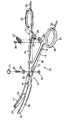
図1を参照すると、器具10は、内側部材11および外側部材12を有している。両部材11、12は、両フランジ33間にギャップを有する開型ロックボックス13を介して連結されている。用語「内側」および「外側」は、開型ロックボックス13での両部材11、12のそれぞれの位置によって、両部材11、12およびこれらの関連部品を区別するのに使用される。内側部材11は、全体として開型ロックボックス13の内側面内に嵌合されかつ両フランジ33により捕捉される。外側部材12は、全体として開型ロックボックス13の外側面を形成する。
内側部材11は、内側シャンク14と、内側ジョー16と、内側リングハンドル20とを有している。同様に、外側部材12は、外側シャンク15と、外側ジョー17と、外側リングハンドル21とを有している。両リングハンドル20、21は、外科医が器具10を保持しかつ操作できるように設計されている。両ジョー16、17は、対向シール18、19間に組織を掴むように設計されている。Referring to FIG. 1, the
The inner member 11 includes an
各シャンク14、15はそれぞれのラチェットスタブ24、25を有している。ラチェット歯26、27は、両部材11、12を所定位置に保持する態様で相互ロックするように設計されている。両シャンク14、15は、外科医が両ジョーを近付けるように力を加えたとき、片持ちばねの態様で撓まされる。両シャンク14、15が撓むことによって、ラチェット歯26、27の相互ロックによる対向ばね復元力が発生される。
器具10は、ラチェット歯26、27が相互ロックされたときに短絡を引起こさない。これは、電気絶縁材の適当な選択および配置により達成される。好ましい実施形態では、ラチェット歯26、27はポリマー材料からなり、ラチェットスタブ24、25内に圧嵌めされる。好ましい実施形態では、ラチェット歯26、27をラチェットスタブ24、25内に固定するのにラチェットねじ28を使用する。製造時に、ラチェット歯26、27は、素材(ブランク)がラチェットスタブ24、25内に圧嵌めされた後に、該素材から形成することができる。Each
The
第二実施形態では、一方の部材11または12は、該部材の一体部分としてのラチェットスタブおよびラチェット歯を有し、他方の部材12または11は、両ラチェットが係合したときの両部材11、12間の短絡を防止する絶縁層を有している。
開型ロックボックス13は、両部材11、12のピボット継手を形成する機能を有している。また、フランジ33は、両ジョー16、17の整合の維持を補助する横方向支持体を形成する。止血鉗子の標準的な設計では、一般に、閉型ロックボックスが使用されており、この閉型ロックボックスでは、内側部材は外側部材のスロットを介して完全に捕捉される。本発明の開型ロックボックス13は両フランジ33間にギャップを有し、これは閉型ロックボックス設計とは異なっている。開型ロックボックス13のギャップは、電気絶縁ピボットを取付けるのに便利なアクセスを形成する。In the second embodiment, one
The
本発明の電気絶縁ピボットは、ロックボックスねじ30を支持するショルダワッシャ29を有している。ショルダワッシャ29は、両部材11、12間の短絡を防止する電気絶縁材料からなる。ロックボックスねじ30の頭部には、大きいねじキャップ31が嵌合される。ロックボックスねじ30のねじ端部には、小さいねじキャップ32が嵌合される。
各部材11、12は、双極電気外科エネルギ発生器の一方の極に接続される。リングハンドル20、21には電気コネクタ22、23が設けられており、便利な接続点を形成している。両部材11、12は、ステンレス鋼のような導電性材料で形成されている。コネクタ22、23およびシール面18、19を除く両部材11、12の露出面には、絶縁材料をスプレーコーティングするのが好ましい。The electrically insulating pivot of the present invention has a
Each
双極電気外科電流の特性は、電気外科エネルギ発生器の設計により決定される。本発明の実施形態では、発生器は、ピーク−ピーク電圧が130V(ボルト)を超えない出力を有する。これは、電圧が高いとスパークが発生し易くなり、スパークは組織の局部的熱傷を引起こし、このため組織の融着が不能になるからである。本発明の好ましい実施形態は、少なくとも2A(アンペア)のRMSの高周波出力電流を発生できる発生器を有している。高電流は、組織を充分に加熱してコラーゲンを溶融させることから重要である。電流が小さいと、組織の融着が弱くなり、破裂強度が小さくなる。 The characteristics of the bipolar electrosurgical current are determined by the design of the electrosurgical energy generator. In an embodiment of the invention, the generator has an output whose peak-to-peak voltage does not exceed 130 V (volts). This is because sparks are more likely to occur at higher voltages, which can cause localized burns of the tissue, which makes it impossible to fuse the tissue. A preferred embodiment of the present invention comprises a generator capable of generating an RMS high frequency output current of at least 2A (amperes). High current is important because the tissue is heated sufficiently to melt the collagen. When the electric current is small, the fusion of the tissue becomes weak and the burst strength becomes small.
作動時に、器具10は、両シール面18、19間で組織を掴むのに使用される。外科医は両リングハンドル20、21を一緒に握って押圧し、組織に圧力を加える。ラチェット歯26、27は、組織の種類および厚さに基いて、適当なラチェットセッティングに相互ロックされる。双極電気外科電流は器具および組織を通って流れ、組織を溶融させる。
両ジョー16、17は、荷重を受けて曲らないように抵抗する構造および横断面を有している。かくして、工学的解析の目的から、両シャンク部分14、15は、シール面18、19がひとたび相対(mate)したときに片持ち支持梁として機能する。この理想的な片持ち梁の長さは、ロックボックスねじ30からそれぞれのラチェットスタブ24または25の位置まで延びている。各シャンクを、一定ばね定数をもつ片持ちばねとしてモデル化することができる。各ラチェットの位置は、片持ちばねの復元力の作用に抗して両ジョー16、17に特定閉じ力を伝達するように設計される。
ばね定数は、一般に、シャンク材料のヤング係数、シャンクの慣性モーメント、およびシャンク部分14、15の長さの関数である。器具10の両ジョー16、17が一緒に閉じられるとき、各シャンクは片持ち梁に近似する。各シャンク14、15の撓みは応力−歪み曲線のリニア範囲内に留まるものと適正に考えられる。このような梁の挙動は、材料技術者には良く知られている。ばね定数が大きいと、両シール面18、19間に大きい閉じ力が生じる。同様に、ばね定数が小さいと、両シール面18、19間に小さい閉じ力が生じる。適正なばね定数の選択は、シャンク14または15の長さおよび両ラチェットストップ26、27の間の距離に基いて定められる。In operation, the
Both
The spring constant is generally a function of the Young's modulus of the shank material, the moment of inertia of the shank, and the length of the
動物研究での実験結果は、シール面18、19により組織に加えられる圧力の大きさは、適正手術成果を確保する上で重要であることを示唆している。動脈および血管束をシールするには、約3〜16kg/cm2の作動範囲内、好ましくは約7〜13kg/cm2の作動範囲内の組織圧力が有効であることが実証されている。動脈および組織束のシーリングには、約4〜6.5kg/cm2の作動範囲内の組織圧力が特に有効であることが証明されている。
連続的ラチェット位置によって作動範囲内の圧力が発生するように、ラチェット歯26、27の配置に関連してシャンク部分14、15のばね定数を調整することが望まれる。一実施形態では、連続的ラチェット位置は2mm間隔である。Experimental results in animal studies suggest that the amount of pressure applied to the tissue by the sealing surfaces 18, 19 is important in ensuring proper surgical outcome. To seal the arterial and vascular bundles, the operating range of about 3~16kg / cm2, have been demonstrated to be preferably effective tissue pressure in the working range of about 7~13kg / cm2. Tissue pressures in the working range of about 4 to 6.5 kg / cm2 have proven particularly effective for sealing arteries and tissue bundles.
It is desirable to adjust the spring constant of the
組織に加えられる圧力は幾つかの方法で説明できる。技術者は、組織に加えられる圧力の大きさはシール面に接触する組織の表面積に基いて定められると考えるであろう。一実施形態では、各シール面18、19の幅は2〜5mmの範囲内、好ましくは4mmであり、一方、各シール面の長さは10〜30mmの範囲内にあるのが好ましい。実験から、少なくとも1つの相互ロックラチェット位置は、シール面幅1mm当り約400〜650グラムの閉じ力を保持するのが好ましいことが判明している。例えば、シール面18、19の幅が4mmであるならば、閉じ力は1600〜2600グラムの範囲内にあるのが好ましい。一実施形態では、閉じ力が1mm当り525グラムであり、4mm幅のシール面18、19では2100グラムの閉じ力を発生する。 The pressure applied to the tissue can be explained in several ways. The technician will think that the amount of pressure applied to the tissue is determined based on the surface area of the tissue in contact with the sealing surface. In one embodiment, the width of each sealing
実験によれば、局部電流密度により不均一な組織効果が生じることが判明しており、このような効果が生じる可能性を低減させるため、各シール面18、19は、好ましい実施形態では丸みをもった縁部を有している。また、或る実施形態ではテーパ状シール面18、19が有利であることが証明されている。なぜならば、テーパは、シール面18、19の長さに沿って組織に比較的一定の圧力を加えることができるからである。或る実施形態では、閉じ力を幅で除した値が長さに沿ってほぼ一定になるように、シール面18、19の幅が調節される。 Experiments have shown that local current density produces non-uniform tissue effects, and in order to reduce the likelihood of such effects, each sealing
一実施形態では、図1に示すように、両シール面18、19間に少なくとも約0.03mmの最小分離を維持するため、器具には絶縁材料で作られたストップ37が設けられる。ストップ37は、両シール面18、19間に短絡が生じる可能性を低下させる。他の実施形態では、鉗子器具10は第二ストップまたは別のストップ47(図1参照)を有し、該ストップ47は、両シール面18、19間に少なくとも約0.03mmの最小分離を維持するように設計される。ストップは、ロックボックス13の近く、ロックボックスねじ30の近く、または対向シール面18、19に隣接して配置することを考えることができる。ストップ37および/またはストップ47は、約0.03〜0.16mmの範囲内の分離距離を維持するのが好ましい。 In one embodiment, as shown in FIG. 1, the instrument is provided with a
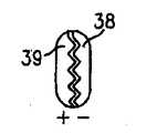
或る実施形態では、図11に示すように、シール面18、19が導電性領域38および絶縁領域39を有し、これらの領域は、対向可能なシール面18、19が対向して相対するときに各導電性領域38が絶縁領域39に対向するように配置される。或る実施形態では、例えばピン/ソケット構造のような標準の機械的インターフェースにより、シール面18、19をそれぞれの部材11、12から着脱可能に構成できる。 In some embodiments, as shown in FIG. 11, the seal surfaces 18, 19 have
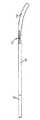
図2は、32mm湾曲シール面の一実施形態を示すものである。図3は、図2の側面図である。図2の部材11、12は、米国鉄鋼研究所(AISI)の410ステンレス鋼から形成される。図2および図3に示されたシャンク部分14、15の長さおよび横断面積は、25ポンド/1インチ撓みのばね定数を与えることが証明されている。 FIG. 2 illustrates one embodiment of a 32 mm curved sealing surface. FIG. 3 is a side view of FIG. 2 are made of 410 stainless steel from the American Institute of Steel Research (AISI). The length and cross-sectional area of the
図4および図5に示す実施形態は、20mm湾曲シール面を有している。図6および図7に示す実施形態は32mm真直シール面を有している。図2〜図7の各実施形態は、標準止血鉗子の外観および感触を有するように設計されている。 The embodiment shown in FIGS. 4 and 5 has a 20 mm curved sealing surface. The embodiment shown in FIGS. 6 and 7 has a 32 mm straight seal surface. Each of the embodiments of FIGS. 2-7 is designed to have the appearance and feel of a standard hemostatic forceps.
図8、図9および図10には、或る実施形態において、部材11、12を連結するロックボックスねじ30の代わりに使用できるショルダピン34が示されている。ショルダピン34は少なくとも1つのランプ(ramp)面35を有し、該ランプ面35は一方の部材11または12と係合して、両ジョー16、17が近付く方向に移動するときに増大する機械的干渉を引起こす。一実施形態では、ショルダピン34は開型ロックボックス13の一部を形成し、シール面18、19の整合を補助する。他の実施形態では、ショルダピン34は開型ロックボックス13を用いることなく使用され、かつフランジ33を用いることなく両部材11、12を移動可能に一緒にピン止めする。加えられた力が、両シール面18、19間に適応作動圧力を付与するのに充分なものとなることを確保するため、締り嵌めは、器具10のキャリブレーションを必要とする。ショルダピンにより引起こされる干渉のレベルに基いて、シャンク部分14、15には僅かに大きいばね定数を使用するのが好ましい。 FIGS. 8, 9 and 10 show a
本発明の双極電気外科器具の使用方法は、次の段階からなる。外科医は、器具10のリングハンドル20、21を掴んで両ジョー16、17を操作する。血管または血管組織が、対向するシール面18、19間で圧縮される。対向シール面18、19は、開型ロックボックス13により、または或る実施形態ではショルダピン34の整合作用により、整合した対向位置に一体化されるのが好ましい。外科医は両部材11、12のシャンク部分14、15を更に撓ませて、ラチェット歯26、27を係合させる。ラチェット歯26、27の係合により、両シャンク部分14、15をこれらの撓み位置に保持して、閉じ力として両ジョー16、17に伝達される一定ばね力を付与する。電気外科エネルギ発生器が、リングハンドル20、21のコネクタ22、23を介して器具10に接続される。電気スイッチを使用して、発生器と器具10との間の回路を閉じる。スイッチは、Valleylab Inc.社(Boulder Colo)から入手できるValleylab カタログ番号E6009のフットスイッチを使用できる。電気外科電流は、それぞれの電気コネクタ22または23とそれぞれのシール面18または19との間の内側および外側部材11、12の各々の導電性経路を通って流れる。外科医を電弧から保護するため、各部材11、12は電気絶縁コーティング36により実質的に覆われている。部材11、12および該部材の関連部品、すなわちハンドル20、21、シャンク14、15およびジョー部材16、17の外面(非対向面)を覆うのに絶縁シースを使用することもできる。 The method of using the bipolar electrosurgical instrument of the present invention comprises the following steps. The surgeon grasps the ring handles 20, 21 of the
ジョー部材16、17の外面には、作動およびシーリング中にジョー部材(またはジョー部材の関連部品)と周囲の組織との付着を低減させるように設計されたニッケルベース材料、コーティング、スタンピング、金属射出成形を設けることを考えることができる。また、シャンク14、15およびリングハンドル20、21等の他の部品を同じ材料または別の「非付着性」材料でコーティングすることも考えられる。非付着性材料は、機械的な歯の作用による付着を防止する円滑面を形成するクラスの材料である。
ジョー部材16、17のそれぞれの組織シール面18、19は、次の「非付着性」材料すなわち、ニッケル−クロム、窒化クロム、オハイオ州のElectrolizing Corporation社の製造に係るメドコート(MedCoat)2000、インコネル(Inconel)600および錫−ニッケルのうちの1つから製造できる。例えば高ニッケル−クロム合金およびNi200、Ni201(〜100%Ni)は、金属射出成形、スタンピング、マシニングまたは任意の同様な方法により電極またはシール面に成形できる。
また、これらの材料は、表面組織、および生物学的組織の存在における電気的効果および腐蝕による表面破壊を受け易いことによる付着をなくすための最適表面エネルギを有することが好ましい。これらの材料は、ステンレス鋼よりも優れた非付着性を呈すると考えられ、圧力およびRFエネルギへの露出により組織付着を一層受け易い領域内で器具に使用すべきである。理解されようが、シーリング中に組織が「付着」する量を低減させることにより、器具の全体的効果が高められる。The outer surfaces of the
Each
Also, these materials preferably have an optimum surface energy to eliminate adhesion due to electrical effects in the presence of surface tissues and biological tissues and surface breakdown due to corrosion. These materials are believed to exhibit better non-adhesiveness than stainless steel and should be used in instruments in areas that are more susceptible to tissue attachment due to exposure to pressure and RF energy. As will be appreciated, reducing the amount of tissue “attachment” during sealing increases the overall effectiveness of the instrument.
組織シール面18、19はまた、1つ以上の上記材料で「被覆」して同じ結果すなわち「非付着面」を達成することができる。例えば、蒸着製造技術を用いて、他のベース材料(金属または非金属)上へのコーティングとして窒化物コーティング(または1つ以上の他の上記材料)を堆積させることができる。
本願に開示する1つの特定クラスの材料は、優れた非付着性を有し、或る場合には優れたシール性を有する。例えば、TiN、ZrN、TiAlNおよびCrNを含む窒化物(但し、これらに限定されない)は、非付着の目的で使用される好ましい材料である。CrNは、その全表面特性および性能の点で非付着目的に特に有効であることが判明している。他のクラスの材料も全体的な付着性を低下させることが判明している。例えば、約5:1のNi/Cr比をもつ高ニッケル/クロム合金は、双極電気外科器具での付着を大幅に低下させることが判明している。このクラスの特に有効な1つの非付着性材料としてインコネル(Inconel)600がある。Ni200、Ni201(〜100%Ni)で形成されているかこれらがコーティングされている電極を備えた双極電気外科器具も、一般的な双極ステンレス鋼電極に比べて優れた非付着性を有することが証明されている。
上記実施形態は本発明の原理の単なる例示用途であると理解すべきである。当業者ならば、本発明の精神および範囲から逸脱することなく多くの変更および他の構成を考えることができるであろう。特許請求の範囲の記載は、これらの変更および構成をカバーするものである。Tissue sealing surfaces 18, 19 can also be “coated” with one or more of the above materials to achieve the same result, ie, a “non-stick surface”. For example, vapor deposition manufacturing techniques can be used to deposit a nitride coating (or one or more other such materials) as a coating on other base materials (metal or non-metal).
One particular class of materials disclosed herein has excellent non-stick properties and in some cases has excellent sealing properties. For example, nitrides including but not limited to TiN, ZrN, TiAlN and CrN are preferred materials used for non-stick purposes. CrN has been found to be particularly effective for non-stick purposes in terms of its overall surface properties and performance. Other classes of materials have also been found to reduce overall adhesion. For example, a high nickel / chromium alloy with a Ni / Cr ratio of about 5: 1 has been found to significantly reduce adhesion in bipolar electrosurgical instruments. One particularly effective non-stick material of this class is Inconel 600. Bipolar electrosurgical instruments with electrodes made of or coated with Ni200, Ni201 (~ 100% Ni) also proved to have superior non-adhesive properties compared to common bipolar stainless steel electrodes Has been.
It should be understood that the above embodiments are merely exemplary applications of the principles of the present invention. Many modifications and other arrangements will occur to those skilled in the art without departing from the spirit and scope of the invention. The scope of the claims covers these modifications and configurations.
10 双極電気外科器具
11 内側部材
12 外側部材
13 開型ロックボックス
16 内側ジョー
17 外側ジョー
18、19シール面
26、27 ラチェット歯
34 ショルダピン
35 ランプ面
37、47 ストップ
38 導電性領域
39 絶縁領域DESCRIPTION OF
Claims (14)
Translated fromJapanese内側および外側部材の対向シール面を電気外科エネルギ源に電気的に接続する少なくとも1つのコネクタと、
対向シール面間の最小分離距離を維持するためのストップと、
内側部材および外側部材のうちの一方の部材に設けられたラチェットと、他方の部材に設けられた少なくとも1つの補完相互ロックする機械的インターフェースとを更に有し、ラチェットおよび相互ロックする機械的インターフェースは、約7〜13kg/cm2の範囲内の閉じ圧力を維持することができることを特徴とする双極電気外科器具。Having inner and outer members, each member is provided with an opposing sealing surface;
At least one connector for electrically connecting opposing sealing surfaces of the inner and outer members to an electrosurgical energy source;
A stop to maintain a minimum separation distance between opposing sealing surfaces;
And further comprising a ratchet provided on one of the inner member and the outer member and at least one complementary interlocking mechanical interface provided on the other member, the ratchet and interlocking mechanical interface comprising: , bipolar electrosurgical instrument, wherein a can be maintained closed pressure within the range of about 7~13kg / cm2.
第一および第二ジョー部材を有し、各ジョー部材には対向シール面が設けられ、第一および第二ジョー部材は、対向シール面が互いに間隔を隔てた関係に配置される第一位置から、対向シール面がこれらの間に組織を掴むことができるように互いに接近して配置される第二位置へと移動でき、
対向シール面と電気的に導通している少なくとも1つのコネクタを有し、該コネクタは、対向シール面を電気外科エネルギ源に電気的に接続して、器具の使用中に対向シール面間に配置された組織に電気外科エネルギを通し、
第一および第二ジョー部材が第二位置に移動されたときに、対向シール面間に最小分離距離を維持するための、少なくとも一方の対向シール面に配置されたストップと、
ラチェットおよび補完相互ロックする機械的インターフェースとを更に有し、ラチェットおよび機械的インターフェースの各々は、第一および第二ジョー部材に配置されて、対向シール面間に約3〜16kg/cm2の範囲内の閉じ圧力を維持する少なくとも1つの相互ロック位置を定めることを特徴とする双極電気外科器具。In bipolar electrosurgical instruments,
A first and a second jaw member, each jaw member being provided with an opposing seal surface, the first and second jaw members from a first position where the opposing seal surfaces are spaced apart from each other; , Can move to a second position that is placed close together so that the opposing sealing surfaces can grip tissue between them,
At least one connector in electrical communication with the opposing sealing surface, the connector electrically connecting the opposing sealing surface to an electrosurgical energy source and disposed between the opposing sealing surfaces during use of the instrument Pass electrosurgical energy through the treated tissue,
A stop disposed on at least one opposing seal surface to maintain a minimum separation distance between the opposing seal surfaces when the first and second jaw members are moved to the second position;
A ratchet and a complementary interlocking mechanical interface, each of the ratchet and mechanical interface being disposed on the first and second jaw members and in the range of about 3-16 kg / cm2 between the opposing sealing surfaces. A bipolar electrosurgical instrument characterized in that it defines at least one interlocking position that maintains a closing pressure therein.
内側および外側部材を有し、各部材は対向シール面が設けられたジョー部材を備え、内側および外側部材は、対向シール面が互いに間隔を隔てた関係に配置される第一位置から、対向シール面間に組織を掴むことができる第二位置へと移動でき、対向シール面はシーリング手術中に組織の付着を低減させる非付着性材料を備え、
対向シール面と電気的に導通している少なくとも1つのコネクタを有し、該コネクタは、対向シール面を電気外科エネルギ源に電気的に接続して、器具の使用中に対向シール面間に配置された組織に電気外科エネルギを通し、
内側および外側部材が第二位置に移動されたときに、対向シール面間に最小分離距離を維持するための、少なくとも一方の対向シール面に隣接して配置された少なくとも1つのストップと、
内側部材および外側部材のうちの一方の部材に配置されたラチェットおよび他方の部材に配置された補完相互ロックする機械的インターフェースとを更に有し、ラチェットおよび補完相互ロックする機械的インターフェースは、対向シール面間に約3〜16kg/cm2の範囲内の閉じ圧力を維持する少なくとも1つの相互ロック位置を定めることを特徴とする双極電気外科器具。In bipolar electrosurgical instruments,
The inner and outer members each have a jaw member provided with an opposing seal surface, the inner and outer members having an opposing seal from a first position where the opposing seal surfaces are disposed in spaced relation to each other. Can be moved to a second position where tissue can be gripped between the faces, and the opposing sealing surface comprises a non-adhesive material that reduces tissue adhesion during sealing surgery;
At least one connector in electrical communication with the opposing sealing surface, the connector electrically connecting the opposing sealing surface to an electrosurgical energy source and disposed between the opposing sealing surfaces during use of the instrument Pass electrosurgical energy through the treated tissue,
At least one stop disposed adjacent to at least one opposing seal surface to maintain a minimum separation distance between the opposing seal surfaces when the inner and outer members are moved to the second position;
A ratchet disposed on one of the inner member and the outer member and a complementary interlocking mechanical interface disposed on the other member, the ratchet and the complementary interlocking mechanical interface comprising a counter seal A bipolar electrosurgical instrument characterized in that it defines at least one interlocking position that maintains a closing pressure in the range of about 3-16 kg / cm2 between the faces.
内側および外側部材を有し、各部材は対向シール面が設けられたジョー部材を備え、内側および外側部材は、対向シール面が互いに間隔を隔てた関係に配置される第一位置から、対向シール面間に組織を掴むことができる第二位置へと移動でき、少なくとも一方のジョー部材の外面には非付着性コーティングが設けられ、
対向シール面と電気的に導通している少なくとも1つのコネクタを有し、該コネクタは、対向シール面を電気外科エネルギ源に電気的に接続して、器具の使用中に対向シール面間に配置された組織に電気外科エネルギを通し、
内側および外側部材が第二位置に移動されたときに、対向シール面間に最小分離距離を維持するための、少なくとも一方の対向シール面に隣接して配置された少なくとも1つのストップと、
内側部材および外側部材のうちの一方の部材に配置されたラチェットおよび他方の部材に配置された補完相互ロックする機械的インターフェースとを更に有し、ラチェットおよび補完相互ロックする機械的インターフェースは、対向シール面間に約3〜16kg/cm2の範囲内の閉じ圧力を維持する少なくとも1つの相互ロック位置を定めることを特徴とする双極電気外科器具。In bipolar electrosurgical instruments,
The inner and outer members each have a jaw member provided with an opposing sealing surface, the inner and outer members having an opposing seal from a first position where the opposing sealing surfaces are spaced apart from each other. Can be moved to a second position where tissue can be grasped between the surfaces, and the outer surface of at least one jaw member is provided with a non-adhesive coating;
Having at least one connector in electrical communication with the opposing sealing surface, the connector electrically connecting the opposing sealing surface to an electrosurgical energy source and disposed between the opposing sealing surfaces during use of the instrument Pass electrosurgical energy through the treated tissue,
At least one stop disposed adjacent to at least one opposing seal surface to maintain a minimum separation distance between the opposing seal surfaces when the inner and outer members are moved to the second position;
A ratchet disposed on one of the inner member and the outer member and a complementary interlocking mechanical interface disposed on the other member, the ratchet and the complementary interlocking mechanical interface comprising a counter seal A bipolar electrosurgical instrument characterized in that it defines at least one interlocking position that maintains a closing pressure in the range of about 3-16 kg / cm2 between the faces.
内側および外側部材を有し、各部材は対向シール面が設けられたジョー部材を備え、内側および外側部材は、対向シール面が互いに間隔を隔てた関係に配置される第一位置から、対向シール面間に組織を掴むことができる第二位置へとピボットの回りで回転でき、対向シール面はその長さ方向に沿ってテーパ状になっており、
対向シール面と電気的に導通している少なくとも1つのコネクタを有し、該コネクタは、対向シール面を電気外科エネルギ源に電気的に接続して、器具の使用中に対向シール面間に配置された組織に電気外科エネルギを通し、
内側および外側部材が第二位置に移動されたときに、対向シール面間に最小分離距離を維持するための、少なくとも一方の対向シール面に配置された少なくとも1つのストップと、
内側部材および外側部材のうちの一方の部材に配置されたラチェットおよび他方の部材に配置された補完相互ロックする機械的インターフェースとを更に有し、ラチェットおよび補完相互ロックする機械的インターフェースは、対向シール面間に約3〜16kg/cm2の範囲内の閉じ圧力を維持する少なくとも1つの相互ロック位置を定めることを特徴とする双極電気外科器具。In bipolar electrosurgical instruments,
The inner and outer members each have a jaw member provided with an opposing seal surface, the inner and outer members having an opposing seal from a first position where the opposing seal surfaces are disposed in spaced relation to each other. Can rotate around the pivot to a second position where the tissue can be gripped between the faces, the opposing sealing face is tapered along its length,
At least one connector in electrical communication with the opposing sealing surface, the connector electrically connecting the opposing sealing surface to an electrosurgical energy source and disposed between the opposing sealing surfaces during use of the instrument Pass electrosurgical energy through the treated tissue,
At least one stop disposed on at least one opposing seal surface to maintain a minimum separation distance between the opposing seal surfaces when the inner and outer members are moved to the second position;
A ratchet disposed on one of the inner member and the outer member and a complementary interlocking mechanical interface disposed on the other member, the ratchet and the complementary interlocking mechanical interface comprising a counter seal A bipolar electrosurgical instrument characterized in that it defines at least one interlocking position that maintains a closing pressure in the range of about 3-16 kg / cm2 between the faces.
Priority Applications (1)
| Application Number | Priority Date | Filing Date | Title |
|---|---|---|---|
| JP2004382576AJP2006167403A (en) | 2004-12-15 | 2004-12-15 | Bipolar electrosurgical instrument for sealing blood vessel |
Applications Claiming Priority (1)
| Application Number | Priority Date | Filing Date | Title |
|---|---|---|---|
| JP2004382576AJP2006167403A (en) | 2004-12-15 | 2004-12-15 | Bipolar electrosurgical instrument for sealing blood vessel |
Publications (1)
| Publication Number | Publication Date |
|---|---|
| JP2006167403Atrue JP2006167403A (en) | 2006-06-29 |
Family
ID=36668735
Family Applications (1)
| Application Number | Title | Priority Date | Filing Date |
|---|---|---|---|
| JP2004382576APendingJP2006167403A (en) | 2004-12-15 | 2004-12-15 | Bipolar electrosurgical instrument for sealing blood vessel |
Country Status (1)
| Country | Link |
|---|---|
| JP (1) | JP2006167403A (en) |
Cited By (11)
| Publication number | Priority date | Publication date | Assignee | Title |
|---|---|---|---|---|
| JP2013528449A (en)* | 2010-06-07 | 2013-07-11 | ジャスト ライト サージカル,リミティド ライアビリティ カンパニー | Apparatus and method for sealing tissue with low power |
| US8551088B2 (en) | 2008-03-31 | 2013-10-08 | Applied Medical Resources Corporation | Electrosurgical system |
| KR101435700B1 (en) | 2007-02-19 | 2014-09-01 | 시너지틱스, 아이엔씨. | Non-Attached Bipolar Forceps |
| KR101567542B1 (en) | 2014-03-18 | 2015-11-20 | 순천향대학교 산학협력단 | Cervix clamp |
| US9320563B2 (en) | 2010-10-01 | 2016-04-26 | Applied Medical Resources Corporation | Electrosurgical instruments and connections thereto |
| US10149713B2 (en) | 2014-05-16 | 2018-12-11 | Applied Medical Resources Corporation | Electrosurgical system |
| US10420603B2 (en) | 2014-12-23 | 2019-09-24 | Applied Medical Resources Corporation | Bipolar electrosurgical sealer and divider |
| US10792092B2 (en) | 2014-05-30 | 2020-10-06 | Applied Medical Resources Corporation | Electrosurgical seal and dissection systems |
| USD904611S1 (en) | 2018-10-10 | 2020-12-08 | Bolder Surgical, Llc | Jaw design for a surgical instrument |
| US11696796B2 (en) | 2018-11-16 | 2023-07-11 | Applied Medical Resources Corporation | Electrosurgical system |
| US11864812B2 (en) | 2018-09-05 | 2024-01-09 | Applied Medical Resources Corporation | Electrosurgical generator control system |
- 2004
- 2004-12-15JPJP2004382576Apatent/JP2006167403A/enactivePending
Cited By (33)
| Publication number | Priority date | Publication date | Assignee | Title |
|---|---|---|---|---|
| KR101435700B1 (en) | 2007-02-19 | 2014-09-01 | 시너지틱스, 아이엔씨. | Non-Attached Bipolar Forceps |
| US11660136B2 (en) | 2008-03-31 | 2023-05-30 | Applied Medical Resources Corporation | Electrosurgical system |
| US12295642B2 (en) | 2008-03-31 | 2025-05-13 | Applied Medical Resources Corporation | Electrosurgical system |
| US8568411B2 (en) | 2008-03-31 | 2013-10-29 | Applied Medical Resources Corporation | Electrosurgical system |
| US8579894B2 (en) | 2008-03-31 | 2013-11-12 | Applied Medical Resources Corporation | Electrosurgical system |
| US8551088B2 (en) | 2008-03-31 | 2013-10-08 | Applied Medical Resources Corporation | Electrosurgical system |
| US8915910B2 (en) | 2008-03-31 | 2014-12-23 | Applied Medical Resources Corporation | Electrosurgical system |
| US8562598B2 (en) | 2008-03-31 | 2013-10-22 | Applied Medical Resources Corporation | Electrosurgical system |
| US10888371B2 (en) | 2008-03-31 | 2021-01-12 | Applied Medical Resources Corporation | Electrosurgical system |
| US9566108B2 (en) | 2008-03-31 | 2017-02-14 | Applied Medical Resources Corporation | Electrosurgical system |
| US10342604B2 (en) | 2008-03-31 | 2019-07-09 | Applied Medical Resources Corporation | Electrosurgical system |
| JP2019084380A (en)* | 2010-06-07 | 2019-06-06 | ジャストライト サージカル,リミティド ライアビリティ カンパニー | Device and method for sealing tissue with low power |
| US11399884B2 (en) | 2010-06-07 | 2022-08-02 | Bolder Surgical, Llc | Low power tissue sealing device and method |
| JP2013528449A (en)* | 2010-06-07 | 2013-07-11 | ジャスト ライト サージカル,リミティド ライアビリティ カンパニー | Apparatus and method for sealing tissue with low power |
| US10166064B2 (en) | 2010-06-07 | 2019-01-01 | Just Right Surgical, Llc | Low-power tissue sealing device and method |
| US9144455B2 (en) | 2010-06-07 | 2015-09-29 | Just Right Surgical, Llc | Low power tissue sealing device and method |
| US11998260B2 (en) | 2010-06-07 | 2024-06-04 | Bolder Surgical, Llc | Low-power tissue sealing device and method |
| US9265561B2 (en) | 2010-06-07 | 2016-02-23 | Just Right Surgical, Llc | Low power tissue sealing device and method |
| US10874452B2 (en) | 2010-10-01 | 2020-12-29 | Applied Medical Resources Corporation | Electrosurgical instruments and connections thereto |
| US12357374B2 (en) | 2010-10-01 | 2025-07-15 | Applied Medical Resources Corporation | Electrosurgical instruments and connections thereto |
| US9962222B2 (en) | 2010-10-01 | 2018-05-08 | Applied Medical Resources Corporation | Electrosurgical instruments and connections thereto |
| US9320563B2 (en) | 2010-10-01 | 2016-04-26 | Applied Medical Resources Corporation | Electrosurgical instruments and connections thereto |
| KR101567542B1 (en) | 2014-03-18 | 2015-11-20 | 순천향대학교 산학협력단 | Cervix clamp |
| US10149713B2 (en) | 2014-05-16 | 2018-12-11 | Applied Medical Resources Corporation | Electrosurgical system |
| US11672589B2 (en) | 2014-05-16 | 2023-06-13 | Applied Medical Resources Corporation | Electrosurgical system |
| US10792092B2 (en) | 2014-05-30 | 2020-10-06 | Applied Medical Resources Corporation | Electrosurgical seal and dissection systems |
| US12239359B2 (en) | 2014-05-30 | 2025-03-04 | Applied Medical Resources Corporation | Electrosurgical seal and dissection systems |
| US10420603B2 (en) | 2014-12-23 | 2019-09-24 | Applied Medical Resources Corporation | Bipolar electrosurgical sealer and divider |
| US12029472B2 (en) | 2014-12-23 | 2024-07-09 | Applied Medical Resources Corporation | Bipolar electrosurgical sealer and divider |
| US11540871B2 (en) | 2014-12-23 | 2023-01-03 | Applied Medical Resources Corporation | Bipolar electrosurgical sealer and divider |
| US11864812B2 (en) | 2018-09-05 | 2024-01-09 | Applied Medical Resources Corporation | Electrosurgical generator control system |
| USD904611S1 (en) | 2018-10-10 | 2020-12-08 | Bolder Surgical, Llc | Jaw design for a surgical instrument |
| US11696796B2 (en) | 2018-11-16 | 2023-07-11 | Applied Medical Resources Corporation | Electrosurgical system |
Similar Documents
| Publication | Publication Date | Title |
|---|---|---|
| US7241296B2 (en) | Bipolar electrosurgical instrument for sealing vessels | |
| US6352536B1 (en) | Bipolar electrosurgical instrument for sealing vessels | |
| CA2309724C (en) | Bipolar electrosurgical instrument for sealing vessels | |
| JP4461022B2 (en) | Laparoscopic surgical bipolar electrosurgical instrument | |
| AU2003266139B2 (en) | Electrosurgical instrument for sealing vessels | |
| US7828798B2 (en) | Laparoscopic bipolar electrosurgical instrument | |
| US7377920B2 (en) | Laparoscopic bipolar electrosurgical instrument | |
| EP1787596B1 (en) | A bipolar electrosurgical sealing instrument having an improved tissue gripping device | |
| JP2006167403A (en) | Bipolar electrosurgical instrument for sealing blood vessel | |
| AU2004237903A1 (en) | Bipolar electrosurgical instrument for sealing vessels |