JP2006161731A - Fuel injection device - Google Patents
Fuel injection deviceDownload PDFInfo
- Publication number
- JP2006161731A JP2006161731AJP2004356024AJP2004356024AJP2006161731AJP 2006161731 AJP2006161731 AJP 2006161731AJP 2004356024 AJP2004356024 AJP 2004356024AJP 2004356024 AJP2004356024 AJP 2004356024AJP 2006161731 AJP2006161731 AJP 2006161731A
- Authority
- JP
- Japan
- Prior art keywords
- fuel
- valve
- fuel injection
- discharge electrode
- nozzle hole
- Prior art date
- Legal status (The legal status is an assumption and is not a legal conclusion. Google has not performed a legal analysis and makes no representation as to the accuracy of the status listed.)
- Pending
Links
- 239000000446fuelSubstances0.000titleclaimsabstractdescription176
- 238000002347injectionMethods0.000titleclaimsabstractdescription158
- 239000007924injectionSubstances0.000titleclaimsabstractdescription158
- 238000002485combustion reactionMethods0.000claimsabstractdescription42
- 230000007246mechanismEffects0.000claimsabstractdescription12
- 230000002093peripheral effectEffects0.000claimsdescription18
- 239000012212insulatorSubstances0.000claimsdescription11
- 239000000567combustion gasSubstances0.000abstractdescription8
- 239000000243solutionSubstances0.000abstract1
- 210000002381plasmaAnatomy0.000description40
- 238000000034methodMethods0.000description16
- QVGXLLKOCUKJST-UHFFFAOYSA-Natomic oxygenChemical compound[O]QVGXLLKOCUKJST-UHFFFAOYSA-N0.000description9
- 229910052760oxygenInorganic materials0.000description9
- 239000001301oxygenSubstances0.000description9
- 230000006870functionEffects0.000description8
- 239000007921spraySubstances0.000description8
- 230000009471actionEffects0.000description7
- 238000010586diagramMethods0.000description7
- 150000002500ionsChemical class0.000description7
- 230000001105regulatory effectEffects0.000description6
- 239000007788liquidSubstances0.000description5
- 230000001276controlling effectEffects0.000description4
- 239000003502gasolineSubstances0.000description4
- 230000002940repellentEffects0.000description4
- 239000005871repellentSubstances0.000description4
- XLYOFNOQVPJJNP-UHFFFAOYSA-NwaterSubstancesOXLYOFNOQVPJJNP-UHFFFAOYSA-N0.000description4
- 238000003466weldingMethods0.000description4
- OKTJSMMVPCPJKN-UHFFFAOYSA-NCarbonChemical compound[C]OKTJSMMVPCPJKN-UHFFFAOYSA-N0.000description3
- 238000000889atomisationMethods0.000description3
- 229910052799carbonInorganic materials0.000description3
- 230000000694effectsEffects0.000description3
- 239000002828fuel tankSubstances0.000description3
- 239000000463materialSubstances0.000description3
- 239000000203mixtureSubstances0.000description3
- 238000009718spray depositionMethods0.000description3
- 230000008859changeEffects0.000description2
- 238000006243chemical reactionMethods0.000description2
- 150000001875compoundsChemical class0.000description2
- 239000000498cooling waterSubstances0.000description2
- 230000006378damageEffects0.000description2
- 238000001514detection methodMethods0.000description2
- 239000000696magnetic materialSubstances0.000description2
- 230000003685thermal hair damageEffects0.000description2
- 239000004215Carbon black (E152)Substances0.000description1
- 238000009825accumulationMethods0.000description1
- 230000002457bidirectional effectEffects0.000description1
- 230000000903blocking effectEffects0.000description1
- 238000007664blowingMethods0.000description1
- 239000011203carbon fibre reinforced carbonSubstances0.000description1
- 230000006835compressionEffects0.000description1
- 238000007906compressionMethods0.000description1
- 230000007423decreaseEffects0.000description1
- 238000000151depositionMethods0.000description1
- 238000005265energy consumptionMethods0.000description1
- 125000003709fluoroalkyl groupChemical group0.000description1
- 230000004907fluxEffects0.000description1
- 239000007789gasSubstances0.000description1
- 229930195733hydrocarbonNatural products0.000description1
- 150000002430hydrocarbonsChemical class0.000description1
- 239000002184metalSubstances0.000description1
- 238000002156mixingMethods0.000description1
- 239000003921oilSubstances0.000description1
- 238000007254oxidation reactionMethods0.000description1
- 229920000642polymerPolymers0.000description1
- 230000008569processEffects0.000description1
- 229910052710siliconInorganic materials0.000description1
- 239000010703siliconSubstances0.000description1
- 238000003980solgel methodMethods0.000description1
- 230000003313weakening effectEffects0.000description1
Images


Landscapes
- Fuel-Injection Apparatus (AREA)
Abstract
Description
Translated fromJapanese本発明は、燃料噴射装置に関し、例えば内燃機関の燃料噴射装置において、燃焼室に燃料を噴射供給する燃料噴射弁のデポジットの付着等を抑制する装置に適用して好適なものである。 The present invention relates to a fuel injection device, and is suitably applied to a device that suppresses deposits and the like of a fuel injection valve that injects fuel into a combustion chamber, for example, in a fuel injection device of an internal combustion engine.
燃料噴射装置としては、例えば内燃機関の燃焼室に直接あるいは間接的に燃料噴射するインジェクタが知られている。インジェクタから供給された燃料は、吸気管あるいは燃焼室において空気と混合され、燃焼室内に可燃混合気を形成する。燃焼室内の可燃混合気はピストン運動により圧縮された後、点火装置により着火燃焼し、内燃機関の動力として利用されている。この種の燃料噴射装置は、内燃機関の気筒に搭載され、燃料を噴射する噴孔などの噴孔部と、燃料噴射を停止および供給する弁部とを有する燃料噴射弁がある(特許文献1、2参照)。 As a fuel injection device, for example, an injector that directly or indirectly injects fuel into a combustion chamber of an internal combustion engine is known. The fuel supplied from the injector is mixed with air in the intake pipe or the combustion chamber to form a combustible mixture in the combustion chamber. The combustible air-fuel mixture in the combustion chamber is compressed by piston motion, and then ignited and combusted by an ignition device, and is used as power for the internal combustion engine. This type of fuel injection device is mounted on a cylinder of an internal combustion engine and includes a fuel injection valve having an injection hole portion such as an injection hole for injecting fuel and a valve portion for stopping and supplying fuel injection (Patent Document 1). 2).
噴孔部などに残留する未燃燃料が燃焼以外の化学反応等によりデポジット(炭素系の化合物)を生じることがあった。デポジットが噴孔部の内部あるいは周辺に付着すると、燃料噴射量が変動する場合がある。その結果、初期の噴射特性を維持することが難しくなり、内燃機関の性能を左右する噴射燃料と空気との混合比が変化するため、デポジット生成および付着を防止することが重要となっている。 In some cases, unburned fuel remaining in the nozzle hole portion causes deposits (carbon-based compounds) due to chemical reactions other than combustion. If the deposit adheres to the inside or the periphery of the nozzle hole, the fuel injection amount may fluctuate. As a result, it becomes difficult to maintain the initial injection characteristics, and the mixing ratio between the injected fuel and air that affects the performance of the internal combustion engine changes. Therefore, it is important to prevent deposit generation and adhesion.
特許文献1では、エアアシスト式の燃料噴射弁を使用して、燃料を噴射する機能と、その燃料に空気を吹きかける機能を有する噴孔部にデポジットを溜める技術が開示されている。噴孔部出口側の、噴射燃料に吹き付ける空気を供給するエアアシスト通路に、デポジットの溜り代としての溝を設けている。 Patent Document 1 discloses a technique for depositing deposits in an injection hole portion having a function of injecting fuel and a function of blowing air to the fuel using an air assist type fuel injection valve. A groove as a deposit accumulation is provided in an air assist passage for supplying air to be sprayed to the injected fuel on the outlet side of the nozzle hole.
特許文献2では、噴孔部周りにフルオロアルキル基などを含む撥液膜を形成し、デポジットの付着を抑制する技術が開示されている。なお、撥液膜を噴孔の表面に形成する方法としては、例えばゾル−ゲル方法により撥液膜を焼成してその表面に撥液性を持たせている。 Patent Document 2 discloses a technique for forming a liquid repellent film including a fluoroalkyl group around the nozzle hole portion to suppress deposit adhesion. As a method of forming the liquid repellent film on the surface of the nozzle hole, for example, the liquid repellent film is baked by a sol-gel method so that the surface has liquid repellency.
特許文献3では、噴孔部の内部あるいは周辺に付着したデポジットを検出すると、燃料噴射弁から燃料を噴射する燃料圧力を上昇させて、この噴射圧力によりデポジットを除去する技術が開示されている。なお、デポジットの検出方法としては、デポジットが付着し堆積すると、弁部を駆動する電磁駆動部での燃料噴射パルス幅が長くなる現象を利用し、検出する燃料噴射パルス幅が所定の設定値より大きくなった場合には、燃料噴射圧力を上昇させてデポジットを除去するものである。
しかしながら、特許文献1による従来技術では、デポジットをある程度溜めるのみであるため、比較的大量のデポジットが生成されると取り除かれることなく噴孔部に蓄積され、噴射特性に影響を及ぼすおそれがある。また、特許文献2による従来技術では、噴孔部の表面とデポジットの付着を弱める方法であるため、撥液膜が形成された噴孔部であったとしても、長期間の運転あるいは比較的高温な燃焼ガス等に繰り返し被曝されることで、付着抑制の効果が薄れるおそれがある。また、特許文献3による従来技術では、デポジット除去時に、内燃機関に要求される内燃機関の運転状態に適した燃料噴射圧力とは異なる圧力で燃料噴射させることになるため、燃焼安定性を損なうおそれがある。 However, in the prior art according to Patent Document 1, since deposits are only accumulated to some extent, if a relatively large amount of deposits are generated, the deposits are not removed and accumulated in the nozzle hole portion, which may affect the injection characteristics. Further, in the prior art according to Patent Document 2, since it is a method of weakening the adhesion between the surface of the nozzle hole and the deposit, even if the nozzle hole is formed with a liquid repellent film, it can be operated for a long time or at a relatively high temperature. Repeated exposure to various combustion gases or the like may reduce the effect of suppressing adhesion. Further, in the prior art disclosed in Patent Document 3, when the deposit is removed, the fuel is injected at a pressure different from the fuel injection pressure suitable for the operating state of the internal combustion engine required for the internal combustion engine, which may impair combustion stability. There is.
本発明は、このような事情を考慮してなされたものであり、その目的は、内燃機関へ燃料を噴射供給する噴孔などの噴射部を有するものにおいて、燃焼中の火炎もしくは燃焼ガスの影響による噴射部へのデポジット付着を抑制することができる燃料噴射装置を提供することにある。 The present invention has been made in consideration of such circumstances, and its purpose is to have an injection portion such as an injection hole for supplying fuel to an internal combustion engine, and to influence the flame or combustion gas during combustion. An object of the present invention is to provide a fuel injection device capable of suppressing deposit adhesion to an injection part.
また、別の目的は、内燃機関へ燃料を噴射供給する噴孔などの噴射部を有するものにおいて、燃焼中の火炎もしくは燃焼ガスの影響による噴射部へのデポジット付着の抑制を図るとともに、燃焼安定性の確保が可能な燃料噴射装置を提供することにある。 Another object of the present invention is to suppress the deposit adhesion to the injection part due to the influence of the flame or the combustion gas during combustion, and to stabilize the combustion in an injection part such as an injection hole for supplying fuel to the internal combustion engine. An object of the present invention is to provide a fuel injection device capable of ensuring the performance.
本発明は、上記目的を達成するために以下の技術的手段を備える。 In order to achieve the above object, the present invention comprises the following technical means.
即ち、請求項1乃至6記載の発明では、燃料の流れを許容および遮断する弁部と、弁部の先端側に設けられ、弁部の遮断および許容動作により開閉される噴孔とを有する燃料噴射弁とを備え、噴孔から内燃機関へ燃料を噴射する燃料噴射装置において、
弁部の先端側に放電電極を設け、放電電極と噴孔周縁との間に非熱平衡の放電プラズマを生じさせるデポジット除去機構を備えていることを特徴としている。That is, in the inventions according to claims 1 to 6, the fuel includes a valve portion that allows and shuts off the flow of fuel, and an injection hole that is provided on the distal end side of the valve portion and is opened and closed by shutting off and allowing the valve portion. In a fuel injection device comprising an injection valve and injecting fuel from an injection hole to an internal combustion engine,
A discharge electrode is provided on the distal end side of the valve portion, and a deposit removing mechanism for generating non-thermal equilibrium discharge plasma is provided between the discharge electrode and the peripheral edge of the nozzle hole.
これによると、燃料を噴射および停止する弁部と、弁部の先端側に設けられ、弁部動作により開閉される噴孔とを有する燃料噴射弁とを備え、噴孔から内燃機関へ燃料を噴射する燃料噴射装置において、弁部の先端側に放電電極を設け、放電電極と噴孔周縁との間に非熱平衡の放電プラズマを生じさせるデポジット除去機構を備えるので、噴孔および噴孔周縁等の噴孔部にデポジットが付着し堆積する場合があっても、放電電極と噴孔周縁との間に生じさせる非熱平衡の放電プラズマにより、噴射部に付着したデポジットを除去することが可能である。したがって、燃焼中の火炎もしくは燃焼ガスの影響による噴射部へのデポジット付着を抑制することができる。 According to this, there is provided a fuel injection valve having a valve portion for injecting and stopping fuel, and an injection hole that is provided at the distal end side of the valve portion and is opened and closed by the operation of the valve portion, and fuel is supplied from the injection hole to the internal combustion engine. In the fuel injection device for injection, a discharge electrode is provided on the tip side of the valve portion, and a deposit removing mechanism for generating non-thermal equilibrium discharge plasma between the discharge electrode and the peripheral edge of the injection hole is provided. It is possible to remove deposits adhering to the injection part by non-thermal equilibrium discharge plasma generated between the discharge electrode and the peripheral edge of the injection hole even if deposits may adhere to and accumulate on the injection hole part. . Therefore, it is possible to suppress deposit adhesion to the injection portion due to the influence of the flame or combustion gas during combustion.
また、一般に、電極に高電圧電源を印加する場合、高電圧の印加により電極を加熱する。加熱した電極からの熱伝達等により、デポジットが焼却等する消失温度以上に加熱されると、デポジットが焼却もしくは噴孔および噴孔周縁等の噴孔部から剥離する。しかしながら、消失温度は比較的温度が高く、燃焼室内の燃焼ガス温度に近いかそれ以上の温度に達する場合があるため、燃料噴射弁の弁部が受熱することで、例えば弁部材などの内部作動部材とこれを収容する弁ボディとの熱膨張差によるリフト量変化を生じるなどダメージを受ける場合がある。 In general, when a high voltage power supply is applied to the electrode, the electrode is heated by applying a high voltage. When the deposit is heated to a temperature higher than the disappearing temperature at which the deposit is incinerated or the like due to heat transfer from the heated electrode, the deposit is incinerated or peeled off from the nozzle hole portion such as the nozzle hole and the nozzle hole periphery. However, the vanishing temperature is relatively high and may reach a temperature close to or higher than the temperature of the combustion gas in the combustion chamber. There is a case where damage such as a change in lift amount due to a difference in thermal expansion between the member and the valve body accommodating the member occurs.
これに対し、請求項1乃至6記載の発明では、デポジット除去機構の放電電極により比較的高温ないわゆる熱プラズマではなく、非熱平衡の放電プラズマを生じさせるように構成する。したがって、非熱平衡の放電プラズマの作用により、電子の温度は熱プラズマと同じく比較的高温になるが、イオンや中性子の温度は常温程度で温度上昇しないので、放電対象物である、デポジットが付着する噴射部は非熱平衡の放電プラズマの作用により温度上昇することはない。その結果、弁部等に熱的ダメージを与えることなく、噴射部に付着したデポジットを除去できる。 On the other hand, the invention described in claims 1 to 6 is configured to generate non-thermal equilibrium discharge plasma instead of so-called thermal plasma having a relatively high temperature by the discharge electrode of the deposit removing mechanism. Therefore, due to the action of non-thermal equilibrium discharge plasma, the temperature of electrons becomes relatively high as in the case of thermal plasma, but the temperature of ions and neutrons does not increase at room temperature, so deposits that are discharge objects adhere. The temperature of the injection unit does not increase due to the action of non-thermal equilibrium discharge plasma. As a result, it is possible to remove deposits adhering to the injection portion without causing thermal damage to the valve portion or the like.
また、請求項2に記載の発明では、放電電極は、弁部側でアース接地していることを特徴としている。 Further, the invention according to claim 2 is characterized in that the discharge electrode is grounded on the valve portion side.
一般に、燃料噴射弁を含む燃料噴射装置を、内燃機関で駆動される車両に搭載している場合、主に車両の電源は、例えばバッテリ等の車載用電源である。 Generally, when a fuel injection device including a fuel injection valve is mounted on a vehicle driven by an internal combustion engine, the power source of the vehicle is mainly an on-vehicle power source such as a battery.
これに対し、請求項2に記載の発明では、放電電極は、弁部側でアース接地しているので、放電電極のアース側を車両に搭載する製品である燃料噴射弁側で行なうことができ、バッテリ等の車載用電源から電圧を昇圧する電圧昇圧装置を追加する程度でよい。したがって、噴孔周縁との間に非熱平衡の放電プラズマを生じさせる放電電極を有するデポジット除去機構の構成が簡素に提供することができる。 On the other hand, in the invention according to claim 2, since the discharge electrode is grounded on the valve portion side, the discharge electrode can be performed on the fuel injection valve side which is a product mounted on the vehicle. It is sufficient to add a voltage boosting device that boosts the voltage from an in-vehicle power source such as a battery. Therefore, the structure of the deposit removing mechanism having a discharge electrode that generates non-thermal equilibrium discharge plasma between the nozzle hole periphery can be simply provided.
特に、請求項3に記載の発明では、弁部は、燃料通路を形成する内周面に弁座を有する弁ボディと、弁座に着座および離座する弁部材とを有し、
噴孔は、弁ボディの弁座の下流側の部位、および弁ボディの先端側に設けられる略薄板状部材のうちのいずれか一方に設けられており、
放電電極のアースを、弁ボディで行なうことが好ましい。In particular, in the invention according to claim 3, the valve portion includes a valve body having a valve seat on an inner peripheral surface forming the fuel passage, and a valve member that is seated and separated from the valve seat,
The nozzle hole is provided in any one of a part on the downstream side of the valve seat of the valve body and a substantially thin plate-like member provided on the distal end side of the valve body,
The discharge electrode is preferably grounded by the valve body.
これにより、噴孔が弁ボディおよび略薄板状部材のいずれかに形成されている場合であっても、弁ボディで放電電極のアースを行なうことで、噴孔自体もアース接地されるので、噴孔周縁と放電電極間で非熱平衡の放電プラズマを効率的に発生させることができる。 As a result, even if the nozzle hole is formed in either the valve body or the substantially thin plate member, the nozzle hole itself is grounded by grounding the discharge electrode in the valve body. Non-thermal equilibrium discharge plasma can be efficiently generated between the hole periphery and the discharge electrode.
また、請求項4に記載の発明では、放電電極は噴孔および噴孔の周縁に対峙するように配置され、
放電電極を、噴孔および噴孔の周縁に対峙している部位以外の範囲で絶縁体が覆っていることを特徴としている。Further, in the invention according to claim 4, the discharge electrode is disposed so as to face the peripheral edge of the injection hole and the injection hole,
The discharge electrode is characterized in that the insulator covers the nozzle hole in a range other than the nozzle hole and the part facing the peripheral edge of the nozzle hole.
これによると、除去対象のデポジットが付着する噴孔および噴孔の周縁には、非熱平衡の放電プラズマが発生するように放電電極を対峙させ、その対峙している部位以外の範囲では放電電極を絶縁体で被覆している。したがって、非熱平衡のプラズマを発生する方法として、イオンや中性子の温度は常温程度で温度上昇せず、電子の温度は比較的高温にする程度の電力エネルギを放電電極に注入する際に、絶縁体で無駄な電力エネルギの消費を抑えることができる。 According to this, the discharge electrode is opposed to the nozzle hole to which the deposit to be removed is attached and the peripheral edge of the nozzle hole so that a non-thermal equilibrium discharge plasma is generated. It is covered with an insulator. Therefore, as a method for generating a non-thermal equilibrium plasma, the temperature of ions and neutrons does not increase at room temperature, and when the power energy that makes the temperature of electrons relatively high is injected into the discharge electrode, the insulator Therefore, it is possible to suppress wasteful power energy consumption.
また、請求項5に記載の発明では、噴孔から噴射される燃料の圧力は、2Mpa以上であることを特徴としている。 The invention according to claim 5 is characterized in that the pressure of the fuel injected from the nozzle hole is 2 Mpa or more.
これによると、内燃機関がいわゆる直噴エンジンの場合には、噴孔から噴射される燃料の圧力は2Mpa以上であることが好ましい。これにより、燃焼室内の筒内圧の上昇に対向して燃料噴射弁から燃料を噴射し、噴射した噴霧の微粒化が図れる。 According to this, when the internal combustion engine is a so-called direct injection engine, the pressure of the fuel injected from the injection hole is preferably 2 Mpa or more. Thereby, the fuel is injected from the fuel injection valve in opposition to the increase in the cylinder pressure in the combustion chamber, and atomization of the injected spray can be achieved.
なお、噴孔から噴射される燃料の圧力の上限は、噴霧の微粒化が図れ、燃焼安定性の確保ができる程度の圧力とする。 Note that the upper limit of the pressure of the fuel injected from the nozzle hole is set to a pressure at which atomization of the spray can be achieved and combustion stability can be ensured.
また、請求項6に記載の発明では、放電電極に高電圧を供給する高電圧供給装置と、高電圧供給装置を駆動制御することで、放電電極に電圧を印加する印加パターンを制御する制御手段を備え、
制御手段は、比較的短い周期のパルス電圧を印加するように高電圧供給装置を駆動制御することを特徴としている。In the invention according to claim 6, a high voltage supply device for supplying a high voltage to the discharge electrode, and a control means for controlling an application pattern for applying a voltage to the discharge electrode by controlling the drive of the high voltage supply device. With
The control means is characterized in that the high voltage supply device is driven and controlled so as to apply a pulse voltage having a relatively short period.
これによると、非熱平衡のプラズマを発生する方法として、制御手段は、比較的短い周期のパルス電圧を印加するように高電圧供給装置を駆動制御することが好ましい。これにより、放電電極に比較的短い周期のパルス電圧を印加することによってイオンや中性子が加熱されることがないので、エネルギ効率を高めることができる。 According to this, as a method for generating non-thermal equilibrium plasma, the control means preferably drives and controls the high voltage supply device so as to apply a pulse voltage having a relatively short period. Thereby, since an ion and a neutron are not heated by applying the pulse voltage of a comparatively short period to a discharge electrode, energy efficiency can be improved.
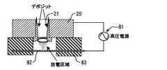
以下、本発明の内燃機関の燃料噴射装置を、ガソリンエンジンに燃料を噴射供給するものに適用して、具体化した実施形態を図面に従って説明する。図1は、本実施形態の燃料噴射装置の構成を表す部分的断面図である。図2は、図1中の弁部における噴孔周縁の周りを示す模式的電気回路図である。図3は、本実施形態に係わる放電電極によるプラズマ放電域とデポジットとの関係を説明する模式図である。図4は、非熱平衡のプラズマのデポジット除去作用を説明する図であって、正高圧電極と接地電極間の放電プラズマ状態を表す模式図である。 DESCRIPTION OF EMBODIMENTS Hereinafter, a specific embodiment of a fuel injection device for an internal combustion engine according to the present invention will be described with reference to the drawings by applying the fuel injection device to a gasoline engine. FIG. 1 is a partial cross-sectional view showing the configuration of the fuel injection device of the present embodiment. FIG. 2 is a schematic electric circuit diagram showing the periphery of the nozzle hole in the valve portion in FIG. FIG. 3 is a schematic diagram for explaining the relationship between the plasma discharge area by the discharge electrode and the deposit according to the present embodiment. FIG. 4 is a diagram for explaining the deposit removal action of non-thermal equilibrium plasma, and is a schematic diagram showing a discharge plasma state between the positive and high voltage electrodes and the ground electrode.
図1に示すように、燃料噴射弁10は、内燃機関、特にガソリンエンジンに用いられる。燃料噴射弁10は、例えば多気筒(例えば4気筒)ガソリンエンジン(以下、エンジンと呼ぶ)の吸気管または各気筒に取付けられて、気筒内の燃焼室に燃料を噴射供給する。なお、本実施形態では、燃料噴射弁10は各気筒に設けられているものとする。燃料噴射弁10には、図示しない燃料ポンプにより加圧された燃料が、燃料分配管(図示せず)を介して供給される。燃料分配管には、一般に、図示しない燃料タンク内の燃料を燃料ポンプ(図示せず)により吸い上げ吐出し、その吐出された燃料が導かれている。なお、吐出される燃料は、図示しないプレーシャレギュレータ等の調圧装置によって所定の圧力に調圧されて、燃料分配管へ送られる。なお、エンジンが直噴エンジンの場合には、エンジンの燃焼室へ供給する燃料の圧力が約2Mpa以上とするため、燃料ポンプによって燃料タンクから吸上げられた所定の低圧(例えば0.2Mpa)の燃料を、図示しない高圧ポンプで加圧し、この加圧された所定の高圧の燃料(例えば、2〜13Mpaの範囲の所定の燃料)が、燃料分配管を介して燃料噴射弁10に供給されている。燃料ポンプから吐出される燃料、高圧ポンプから燃料分配管へ供給された燃料は、図示しないプレーシャレギュレータ等の調圧装置によって所定の圧力に調圧されている。なお、以下、本実施例で説明するエンジンは、ガソリン直噴エンジンとする。 As shown in FIG. 1, the
燃料噴射弁10は、図1に示すように、略円筒形状であり、一端から燃料を受け、内部の燃料通路を経由して他端から燃料を噴射する。燃料噴射弁10は、燃料の噴射を遮断および許容する弁部Bと、弁部Bを駆動する電磁駆動部Sと、デポジット除去機構80とを備えており、一端から燃料通路内に流入した燃料を弁部Bからエンジンの気筒に噴射供給する。 As shown in FIG. 1, the
弁部は、図1に示すように、弁ボディ12と、弁部材としてのニードル30とを含んで構成されている。弁ボディ12の内周には、上記内部燃料通路内を流れる燃料が導かれている。弁ボディ12は燃料流れ方向の噴孔21側に向けて縮径する内周面としての円錐面13を有している。円錐面13には、ニードル30が離座および着座可能である。ニードル30は略軸状に形成され、弁ボディ12内を軸方向に往復移動可能である。なお、ここで、円錐面13は、ニードル30が離座および着座可能な弁座14を構成する。具体的には、弁座14には、ニードル30の当接部31が離座および着座する。なお、ここで、弁座14と当接部31は、弁部が燃料の噴射を停止するための油密機能の働きをするシート部を構成している。 As shown in FIG. 1, the valve portion includes a
弁座14の中央側には、弁座14の燃料流れの下流側に向かって、内部燃料通路と連通可能な噴孔21が配置されている。詳しくは、弁ボディ12の先端側に略薄板状部材としての噴孔プレート20が配置されている。噴孔プレート20は、図1に示すように、有底筒状に形成されており、弁ハウジング16の底部の内壁と弁ボディ12の底部の内壁との間に挟持されている。 An
噴孔プレート20は、例えば薄い金属板状の薄板状体で形成され、複数(本実施例では、図1に作図の便宜上2個)の噴孔21が配置されている。この噴孔21は、要求される燃料の噴霧の形状、方向、数などに応じて、その大きさ、噴孔軸線の方向、噴孔配列等が決定される。また、噴孔の開口面積は、開弁時の流量を規定する。したがって、燃料噴射弁10の燃料噴射量は、噴孔21の開口面積、ニードル30のリフト量と、開弁期間とによって調量されている。ニードル30が弁座14に着座すると噴孔21からの燃料噴射が停止され、ニードル30が弁座14から離座すると噴孔21から燃料が噴射される。 The
なお、弁ボディ12は、弁ハウジング16の燃料噴射側端部の内壁に溶接等により固定されている。弁ボディ12は段付きの略有底円筒状に形成され、弁ハウジング16の下端部の内周側に挿入されている。 The
また、一般に、弁ボディの弁座14には、燃料噴射毎に繰り返しニードル30が着座および離座する等のため、比較的強い耐摩耗性が要求される。これに対し、本実施形態では、弁ボディのうち、弁座14側の部分つまり弁ボディ12を耐摩耗性の比較的強い特定の材料で、電磁駆動部(詳しくは筒部材40)に接続する側の弁ハウジング16を、その特定材料以外の、例えば安価な材料を用いることができる。なお、特許請求の範囲に記載の弁ボディは、図1に示す弁ボディ12および弁ハウジング16とから構成されるものに限らず、弁ボディ12から構成されるものであってもよい。 In general, the
電磁駆動部Sは、図1に示すように、筒部材40、可動コア50、固定コア54、およびコイル60とを有する。 As shown in FIG. 1, the electromagnetic drive unit S includes a
筒部材40は、弁ボディ12(詳しくは弁ハウジング16)の反噴孔側の内周壁に挿入され、溶接により弁ハウジング16を介して弁ボディ12に固定されている。筒部材40は、噴孔21側から第1磁性筒部42、非磁性筒部44、および第2磁性筒部46により構成されている。非磁性筒部44は第1磁性筒部42と第2磁性筒部46との磁気的短絡を防止する。この磁気的短絡防止により、コイル60の通電により発生する電磁力による磁束を、可動コア50、固定コア54、および緩衝コア52に効率的に流れるようにしている。 The
可動コア50は磁性材料で段付きの略円筒状体に形成されており、ニードル30の反噴孔側の端部と溶接等により固定されている。可動コア50はニードル30とともに往復移動する。可動コア50の筒壁を貫通する流出孔52は、可動コア50の筒内外を連通する燃料通路を形成している。 The
固定コア54は磁性材料で略円筒状に形成されている。固定コア54は筒部材40内に挿入されており、筒部材40と溶接により固定されている。固定コア54は可動コア50に対し反噴孔側に設置され、可動コア50に向きあっている。アジャスティングパイプ56は固定コア54の内周に圧入され、内部に燃料通路を形成している。付勢部材としてのスプリング58は一端部でアジャスティングパイプ56に係止され、他端部で可動コア50に係止されている。アジャスティングパイプ56の圧入量を調整することにより、可動コア50に付勢するスプリング58の荷重が変更される。スプリング58の付勢力により可動コア50およびニードル30は弁座14に向けて付勢されている。言い換えると、スプリング58は可動コア50をニードル30の着座方向に付勢する付勢手段を構成する。 The fixed
コイル60はスプール62に巻回されている。ターミナル65はコネクタ64にインサート成形されており、コイル60と電気的に接続している。コイル60に通電すると、可動コア50と固定コア54との間に磁気吸引力が働き、圧縮スプリング58の付勢力に抗して可動コア50は固定コア54側に吸引される。 The
なお、ここで、弁ボディ12とニードル30とは燃料の噴射を遮断および許容する弁部Bを構成する。弁部Bのうち、弁座14と当接部31はシート部を構成する。噴孔プレート20(詳しくは、噴孔21)は燃料を微粒化し、噴霧を形成する燃料噴霧形成手段を構成する。コイル60と可動コア50と固定コア54と筒部材40とスプリング58とは弁部Bを駆動する電磁駆動部Sを構成する。上述の構成を有する燃料噴射弁10は、コネクタ64からコイルに供給する電流を制御することでニードル30のリフトを制御し、内部燃料通路に流入した燃料を弁部Bからエンジンの燃焼室に噴射する。燃料噴射弁10はニードル30を着座方向に付勢するスプリング58を有しており、コイル60への電流供給が停止されると、コイルへ60の電流供給の停止時には、弁部Bが閉弁して噴射を終了する。 Here, the
デポジット除去機構80は、図1および図2に示すように、高電圧供給装置81と、放電電極82とを有している。高電圧供給装置81は、放電電極82に高電圧を印加し、非熱平衡の放電プラズマが放電電極82に発生するのに必要な電力エネルギを供給する。高電圧供給装置81は、ECU90に接続されており、ECU90により駆動制御される。 As shown in FIGS. 1 and 2, the
放電電極82は、図2に示すように、噴孔プレート20上の噴孔20および噴孔20周縁等の噴射部に対峙するように配置されている。放電電極82は、噴孔20および噴孔20周縁に対峙する部位では、放電電極82と噴孔20周縁間に非熱平衡の放電プラズマが発生するようにその対峙する間隔が調節されている。放電電極82のうち、噴孔20および噴孔20周縁に対峙している部位以外の範囲では、シリコン等の絶縁体83によって被覆されている。 As shown in FIG. 2, the
この被覆された放電電極82は、絶縁体83を介して噴孔プレート20および弁ボディ12(詳しくは弁ハウジング)に固定されている。図2に示すように、放電電極82の一端(図2中右側端部)は高電圧供給装置81に電気的に接続され、他端(図2中左側端部)は、絶縁体83に覆われたまま弁ボディ12側に固定されている。弁ボディ12はアース接地され、噴孔プレート20および弁ボディ12は接地電極として機能する。 The covered
制御手段としてのECU90は、図示しないリードオンリメモリ(ROM)、ランダムアクセスメモリ(RAM)、マイクロプロセッサ(CPU)、入力ポート、出力ポートを相互に双方向性バスで接続した公知構成のマイクロコンピュータとして構成されている。このECU90は、バッテリ等の電源を用いて、燃料噴射弁10のターミナル65への通電開始および通電停止を実行することで、燃料噴射弁10への通電期間を制御する。エンジンの回転速度、吸気管圧力(または吸入空気量)、冷却水温等のエンジンの運転状態を検出する図示しない各種センサ91、92、93、94、95、96の信号を読み込み、エンジン用の各種プログラム(図示せず)に従って、燃料噴射弁10の電磁駆動部Sの動作を制御する。なお、詳しくは、クランクシャフトの回転状態に応じて720°CA毎にパルス信号を出力する基準位置センサ91と、より細かなクランク角毎(例えば、30°CA毎)にパルス信号を出力する回転角センサ92とが設けられている。エンジンの図示しないシリンダ(ウォータジャケット)などには、冷却水温を検出するための水温センサ93が配設されている。吸気管には、吸入空気流量を検出するエアフローメータ94などが配設されている。排気管には、排ガス中の酸素濃等に比例し、空燃比信号を出力する空燃比センサ98などが設けられている。また、運転者の要求等を検出するためのアクセルペダルセンサ95、スロットル開度センサ96等が設けられている。 The
ECU90は、高電圧供給装置81を駆動制御することで、放電電極82に電圧を印加する印加パターンを制御する。ECU90は、放電電極82に比較的短い周期(例えばパルス幅が1μS)のパルス電圧を印加するように高電圧供給装置を駆動制御することが好ましい。これにより、放電電極に比較的短い周期のパルス電圧を印加することによってイオンや中性子が加熱されることがないので、非熱平衡のプラズマを発生する方法としてエネルギ効率を高めることができる。なお、エンジンの燃焼室温度を検出する温度センサ97、O2センサなどの空燃比センサ98が設けられていることが好ましい。例えばO2センサ98の検出信号から、ECU90が周知のストイキ制御等空燃比制御し、エンジンの運転状態から最適な燃料噴射パルスの指令パルスを演算し、実際の燃料噴射弁10(詳しくは電磁駆動部S)の燃料噴射パルスを比較し、そのパルス幅の差からデポジットの噴孔21 周縁への付着状態が検出される。The
なお、ECU90は、噴孔2周縁に付着するデポジットが所定量以上であるか否かを判断する機能を有する。デポジットの検出方法としては、上記燃料噴射パルス幅を検出し、その幅が所定値以上に達しているかを判断する方法、温度センサ97により燃焼温度が所定値以上に達しているかを判断する方法、あるいはデポジット除去機能を前回作動させたときからの経過時間が所定時間経過したかを判断する方法などいずれの方法であってもよい。なお、上記経過時間は車両の走行距離で代用してもよい。これにより、噴孔2周縁に付着するデポジット量を所定量以下に抑制することができる。 The
次に、上述した構成を有する本実施形態の燃料噴射装置の作動を説明する。車両のエンジンキーをIG位置にして、図示しないイグニッションスイッチがオン(ON)する等することで、燃料ポンプが駆動され、燃料タンク内に燃料が燃料ポンプにより吸い上げられる。吸い上げられた燃料は、プレッシャレギュレータにより調圧され、所定の低圧燃料が高圧ポンプへ供給される。高圧ポンプによって所定の低圧燃料は加圧され、加圧された燃料が燃料分配管へ供給される。燃料分配管へ供給された燃料は、プレッシャレギュレータにより所定の高圧燃料に調圧されて、燃料分配管内の各分配口から燃料噴射弁10へ供給される。 Next, the operation of the fuel injection device of the present embodiment having the above-described configuration will be described. When the vehicle engine key is set to the IG position and an ignition switch (not shown) is turned on, the fuel pump is driven, and the fuel is sucked into the fuel tank by the fuel pump. The sucked fuel is regulated by a pressure regulator, and a predetermined low pressure fuel is supplied to the high pressure pump. The predetermined low pressure fuel is pressurized by the high pressure pump, and the pressurized fuel is supplied to the fuel distribution pipe. The fuel supplied to the fuel distribution pipe is regulated to a predetermined high-pressure fuel by a pressure regulator and supplied to the
燃料噴射弁10の燃料噴射時には、燃料噴射弁10のコイル60に電流が供給され、ニードル30が弁座14から離座しリフトを開始すると、弁部は開弁され燃料の噴射を開始する。燃料は、噴孔21から噴射され噴霧化されてエンジンの燃焼室等へ供給される。一方、燃料噴射停止時には、コイル60への電流供給が停止され、スプリング58によりニードル30のリフトが減少する。そして、ニードル30が弁座14に着座すると、噴射が終了する。コイル60への通電期間を調節することにより、燃料噴射弁10から噴射される燃料(燃料噴霧)の噴射期間つまり燃料噴射量が調節される。 At the time of fuel injection of the
なお、ここで、放電電極82による非熱平衡の放電プラズマの作用によりデポジットが除去される過程を説明する。まず、非熱平衡の放電プラズマを、図4に従って説明する。非熱平衡の放電プラズマが発生する条件は2つの場合がある。第1の場合は、正高圧電極82と接地電極12、20との間に、局部的に限定されて持続する放電が発生するものである(以下、コロナ放電と呼ぶ)。第2の場合は、いわゆるストリーマ状の細かい放電チャンネルを形成するものである(以下、ストリーマ放電と呼ぶ)。コロナ放電やストリーマ放電などの部分放電が正高圧電極82と接地電極12、20間に発生することで、図4に示すように、電子の温度は比較的高温な10000K以上になるが、イオンや中性子の温度は約300Kとほとんど常温のままで上記放電プラズマによる温度の上昇はみられない。そのため、対象物の噴孔21周縁も約300Kで温度は上がらない。なお、図4に示すように、大気中の酸素(O2)は、室温でも、比較的高温な電子によりOやOHのラジカル基に化学反応する。なお、燃料噴射弁10の周りの雰囲気温度においても同様に酸素(O2)は比較的高温な電子によりOやOHのラジカル基に変換される。このとき、OやOHのラジカル基への変換が行なわれても、正高圧電極82および接地電極12、20へのダメージは生じない。Here, the process of removing deposits by the action of non-thermal equilibrium discharge plasma by the
なお詳しくは、大気中で非熱平衡の放電プラズマが発生すると、1molの酸素分子(O2)は2molのOラジカル基が発生する(O2+e(電子)→2O+e)。1molの酸素分子(O2)と1molのOラジカル基からO3ラジカル基に生成される(O2+O→O3)。1molのOラジカル基と1molの水(H2O)から2molのOHラジカル基が生成される(O+H2O→2OH)。1molの水(H2O)から1molのOラジカル基と1molのOラジカル基が発生する(H2O+e→OH+O+e)。More specifically, when non-thermal equilibrium discharge plasma is generated in the atmosphere, 1 mol of oxygen molecules (O2 ) generates 2 mol of O radical groups (O2 + e (electrons) → 2O + e). It is generated from 1 mol of oxygen molecules (O2 ) and 1 mol of O radical groups to O3 radical groups (O2 + O → O3 ). From 1 mol of O radical group and 1 mol of water (H2 O), 2 mol of OH radical group is generated (O + H2 O → 2OH). 1 mol of O radical group and 1 mol of O radical group are generated from 1 mol of water (H2 O) (H2 O + e → OH + O + e).
なお、ここで、O、OH、およびO3のラジカル基は活性酸素種であり、酸化反応に強く寄与する。なお、化学反応後の電子(e)は室温になり、O3ラジカル基も室温となる。Here, the radical groups of O, OH, and O3 are active oxygen species and strongly contribute to the oxidation reaction. The electron (e) after the chemical reaction is at room temperature, and the O3 radical group is also at room temperature.
これらの非熱平衡の放電プラズマは、図3に示すように噴孔21の周縁および噴孔21の内周においても発生する。デポジットはカーボンおよび炭化水素の重合物いわゆる炭素系の化合物であるため、O、OH、およびO3の活性酸素種によって酸化除去できる。なお、図3において、O、OH、およびO3の活性酸素種は、放電区域近傍で発生する。放電区域近傍で発生する活性酸素種のうち、O、OHは比較的短寿命であり、O3は比較的長寿命であるため、主として比較的長寿命なO3ラジカル基が噴孔21内へ拡散する。These non-thermal equilibrium discharge plasmas are also generated at the periphery of the
次に、本実施形態の作用効果を説明すると、(1)本実施形態では、燃料を噴射および停止する弁部Bと、弁部Bの先端側に設けられ、弁部動作により開閉される噴孔21とを有する燃料噴射弁10とを備え、噴孔21からエンジンへ燃料を噴射する燃料噴射装置において、弁部Bの先端側に放電電極82を設け、放電電極82と噴孔21周縁との間に非熱平衡の放電プラズマを生じさせるデポジット除去機構80を備えている。これにより、噴孔21および噴孔21周縁等の噴孔部にデポジットが付着し堆積する場合があっても、放電電極82と噴孔21周縁との間に生じさせる非熱平衡の放電プラズマにより、噴射部に付着したデポジットを除去することが可能である。したがって、燃焼中の火炎もしくは燃焼ガスの影響による噴射部へのデポジット付着を抑制することができる。 Next, functions and effects of the present embodiment will be described. (1) In the present embodiment, a valve part B that injects and stops fuel, and an injection that is provided on the distal end side of the valve part B and is opened and closed by the valve part operation. In a fuel injection device that includes a
(2)なお、一般に、電極に高電圧電源を印加する場合、高電圧の印加により電極を加熱する。加熱した電極からの熱伝達等により、デポジットが焼却等する消失温度以上に加熱されると、デポジットが焼却もしくは噴孔および噴孔周縁等の噴孔部から剥離する。しかしながら、消失温度は比較的温度が高く、燃焼室内の燃焼ガス温度に近いかそれ以上の温度に達する場合があるため、燃料噴射弁10の弁部Bが受熱することで、例えば弁部材などの内部作動部材とこれを収容する弁ボディとの熱膨張差によるリフト量変化を生じるなどダメージを受ける場合がある。 (2) In general, when a high voltage power source is applied to an electrode, the electrode is heated by applying a high voltage. When the deposit is heated to a temperature higher than the disappearing temperature at which the deposit is incinerated or the like due to heat transfer from the heated electrode, the deposit is incinerated or peeled off from the nozzle hole portion such as the nozzle hole and the nozzle hole periphery. However, since the vanishing temperature is relatively high and may reach a temperature close to or higher than the combustion gas temperature in the combustion chamber, the valve portion B of the
これに対し、本実施形態では、デポジット除去機構80の放電電極82により、比較的高温ないわゆる熱プラズマではなく、非熱平衡の放電プラズマを生じさせるように構成している。したがって、非熱平衡の放電プラズマの作用により、電子の温度は熱プラズマと同じく比較的高温になるが、イオンや中性子の温度は常温程度のままで温度上昇しないので、放電対象物である、デポジットが付着する噴射部つまり弁部Bは非熱平衡の放電プラズマの作用により温度上昇することはない。その結果、弁部B等に熱的ダメージを与えることなく、噴射部に付着したデポジットを除去できる。 On the other hand, in this embodiment, the
(3)さらになお、一般に、燃料噴射弁10を含む燃料噴射装置を、エンジンで駆動される車両に搭載している場合、主に車両の電源は、例えばバッテリ等の車載用電源である。 (3) Furthermore, generally, when the fuel injection device including the
これに対し、本実施形態では、放電電極82は、弁部B側でアース接地しているので、放電電極のアース側を車両に搭載する製品である燃料噴射弁10側で行なうことができ、バッテリ等の車載用電源から電圧を昇圧する電圧昇圧装置を追加する程度でよい。したがって、噴孔21周縁との間に非熱平衡の放電プラズマを生じさせる放電電極82を有するデポジット除去機構80の構成が簡素に提供することができる。 On the other hand, in this embodiment, since the
(4)さらになお、本実施形態では、放電電極のアースを、弁ボディで行なうことが好ましい。なお、噴孔21は、弁ボディ12の弁座14の下流側の部位、および弁ボディ12の先端側に設けられる噴孔プレート20のうちのいずれか一方に設けられる。 (4) Furthermore, in this embodiment, it is preferable that the discharge electrode is grounded by the valve body. The
これにより、噴孔21が弁ボディ12および噴孔プレート20のいずれかに形成されている場合であっても、弁ボディ12で放電電極82のアースを行なうことで、噴孔21自体もアース接地されるため、噴孔21周縁と放電電極82間で非熱平衡の放電プラズマを効率的に発生させることができる。 Thereby, even if the
(5)さらになお、本実施形態では、除去対象のデポジットが付着する噴孔21および噴孔21の周縁には、非熱平衡の放電プラズマが発生するように放電電極82を対峙させ、その対峙している部位以外の範囲では放電電極82を絶縁体83で被覆している。したがって、イオンや中性子の温度は常温程度で温度上昇せず、電子の温度は比較的高温にする程度の電力エネルギを放電電極82に注入する際に、非熱平衡のプラズマを発生する方法として絶縁体83で無駄な電力エネルギの消費を抑えることができる。 (5) Furthermore, in the present embodiment, the
(6)さらになお、本実施形態では、非熱平衡のプラズマを発生する方法として、ECU90は、放電電極82に比較的短い周期のパルス電圧を印加するように高電圧供給装置81を駆動制御することが好ましい。これにより、放電電極82に比較的短い周期のパルス電圧を印加することによってイオンや中性子が加熱されることがないので、エネルギ効率を高めることができる。 (6) Furthermore, in the present embodiment, as a method of generating non-thermal equilibrium plasma, the
(7)なお、エンジンが直噴エンジンの場合には、噴孔21から噴射される燃料の圧力は2Mpa以上であることが好ましい。これにより、燃焼室内の筒内圧の上昇に対向して燃料噴射弁10から燃料を噴射し、噴射した噴霧の微粒化が図れる。 (7) When the engine is a direct injection engine, the pressure of the fuel injected from the
なお、噴孔21から噴射される燃料の圧力の上限は、噴霧の微粒化が図れ、燃焼安定性の確保ができる程度の圧力とする。 The upper limit of the pressure of the fuel injected from the
(他の実施形態)
なお、以上説明した本実施形態では、燃料の噴射を遮断および許容する弁部Bと、噴霧形成手段を有する噴孔プレート20とを有する燃料噴射弁10として説明したが、噴孔プレート20はなく、弁ボディ12の弁座14の下流側に噴孔21が配置され、噴霧形成手段を有する弁部であってもよい。(Other embodiments)
In the above-described embodiment, the
10 燃料噴射弁
12 弁ボディ(接地電極)
13 円錐面(内周面)
14 弁座
20 噴孔プレート(略薄板状部材、接地電極)
21 噴孔
30 ニードル(弁部材)
31 当接部
80 デポジット除去機構
81 高電圧供給装置
82 放電電極
83 絶縁体
90 ECU(制御手段)
B 弁部
S 電磁駆動部10
13 Conical surface (inner peripheral surface)
14
21
31
B Valve part S Electromagnetic drive part
Claims (6)
Translated fromJapanese前記噴孔から内燃機関へ燃料を噴射する燃料噴射装置において、
前記弁部の先端側に放電電極を設け、
前記放電電極と前記噴孔周縁との間に非熱平衡の放電プラズマを生じさせるデポジット除去機構を備えていることを特徴とする燃料噴射装置。A fuel injection valve having a valve portion that allows and shuts off the flow of fuel, and an injection hole that is provided on a distal end side of the valve portion and is opened and closed by a shut-off and allowing operation of the valve portion;
In the fuel injection device for injecting fuel from the nozzle hole to the internal combustion engine,
A discharge electrode is provided on the tip side of the valve part,
A fuel injection device comprising a deposit removing mechanism for generating non-thermal equilibrium discharge plasma between the discharge electrode and the peripheral edge of the nozzle hole.
前記噴孔は、前記弁ボディの前記弁座の下流側の部位、および前記弁ボディの先端側に設けられる略薄板状部材のうちのいずれか一方に設けられており、
前記放電電極のアースを、前記弁ボディで行なうことを特徴とする請求項1または請求項2に記載の燃料噴射装置。The valve portion includes a valve body having a valve seat on an inner peripheral surface forming a fuel passage, and a valve member that is seated on and separated from the valve seat,
The nozzle hole is provided in any one of a portion of the valve body on the downstream side of the valve seat and a substantially thin plate member provided on a distal end side of the valve body,
The fuel injection device according to claim 1, wherein the discharge electrode is grounded by the valve body.
前記放電電極を、前記噴孔および前記噴孔の周縁に対峙している部位以外の範囲で絶縁体が覆っていることを特徴とする請求項1から請求項3のいずれか一項に記載の燃料噴射装置。The discharge electrode is disposed so as to face the nozzle hole and the periphery of the nozzle hole,
4. The insulator according to claim 1, wherein the discharge electrode is covered with an insulator in a range other than the region facing the peripheral edge of the nozzle hole and the nozzle hole. 5. Fuel injection device.
前記高電圧供給装置を駆動制御することで、前記放電電極に電圧を印加する印加パターンを制御する制御手段を備え、
前記制御手段は、比較的短い周期のパルス電圧を印加するように前記高電圧供給装置を駆動制御することを特徴とする請求項1から請求項5のいずれか一項に記載の燃料噴射装置。A high voltage supply device for supplying a high voltage to the discharge electrode;
By controlling the driving of the high voltage supply device, a control means for controlling an application pattern for applying a voltage to the discharge electrode is provided,
The fuel injection device according to any one of claims 1 to 5, wherein the control unit drives and controls the high voltage supply device so as to apply a pulse voltage having a relatively short cycle.
Priority Applications (1)
| Application Number | Priority Date | Filing Date | Title |
|---|---|---|---|
| JP2004356024AJP2006161731A (en) | 2004-12-08 | 2004-12-08 | Fuel injection device |
Applications Claiming Priority (1)
| Application Number | Priority Date | Filing Date | Title |
|---|---|---|---|
| JP2004356024AJP2006161731A (en) | 2004-12-08 | 2004-12-08 | Fuel injection device |
Publications (1)
| Publication Number | Publication Date |
|---|---|
| JP2006161731Atrue JP2006161731A (en) | 2006-06-22 |
Family
ID=36664015
Family Applications (1)
| Application Number | Title | Priority Date | Filing Date |
|---|---|---|---|
| JP2004356024APendingJP2006161731A (en) | 2004-12-08 | 2004-12-08 | Fuel injection device |
Country Status (1)
| Country | Link |
|---|---|
| JP (1) | JP2006161731A (en) |
Cited By (3)
| Publication number | Priority date | Publication date | Assignee | Title |
|---|---|---|---|---|
| JP2008157037A (en)* | 2006-12-20 | 2008-07-10 | Toyota Motor Corp | Internal combustion engine |
| WO2008126942A1 (en)* | 2007-04-11 | 2008-10-23 | Toyota Jidosha Kabushiki Kaisha | Fuel injection device |
| US8794548B2 (en) | 2009-03-05 | 2014-08-05 | Denso Corporation | Formation method of water repellent layer and injector having water repellent layer |
- 2004
- 2004-12-08JPJP2004356024Apatent/JP2006161731A/enactivePending
Cited By (4)
| Publication number | Priority date | Publication date | Assignee | Title |
|---|---|---|---|---|
| JP2008157037A (en)* | 2006-12-20 | 2008-07-10 | Toyota Motor Corp | Internal combustion engine |
| WO2008126942A1 (en)* | 2007-04-11 | 2008-10-23 | Toyota Jidosha Kabushiki Kaisha | Fuel injection device |
| JP2008261264A (en)* | 2007-04-11 | 2008-10-30 | Toyota Motor Corp | Fuel injection device |
| US8794548B2 (en) | 2009-03-05 | 2014-08-05 | Denso Corporation | Formation method of water repellent layer and injector having water repellent layer |
Similar Documents
| Publication | Publication Date | Title |
|---|---|---|
| US7472691B2 (en) | Fuel injection valve | |
| US7043350B2 (en) | Fuel injection control apparatus for internal combustion engine and method thereof, and fuel injection valve | |
| US6857417B2 (en) | Fuel injection nozzle having coating layer and manufacturing method thereof | |
| JP2006336509A (en) | Control device for fuel injection type internal combustion engine | |
| KR101025063B1 (en) | Capillary Fuel Injector with Metering Valve for Internal Combustion Engine | |
| JP2001280189A (en) | Control method of electromagnetic fuel injection valve | |
| US6920861B2 (en) | Fuel injection control devices for internal combustion engines | |
| JP2006161731A (en) | Fuel injection device | |
| CN109328263B (en) | Control device | |
| JP5274701B1 (en) | In-cylinder injection internal combustion engine control device | |
| CN100447395C (en) | Starting device and control method for liquefied petroleum gas injection vehicle | |
| JP2006183469A (en) | Fuel injector | |
| KR100692132B1 (en) | Cutoff Solenoid Injector Structure | |
| JP2006220082A (en) | Fuel injection device | |
| JP3044876B2 (en) | Electronically controlled fuel injection device for internal combustion engines | |
| US11143131B2 (en) | Vehicle control device | |
| JP2008115794A (en) | Ignition device for internal combustion engine | |
| JP2005325704A (en) | Fluid injection valve | |
| JP3968846B2 (en) | Fuel injection device | |
| JPH0949432A (en) | Direct injection type internal combustion engine | |
| JP2006152964A (en) | Fuel injection device | |
| JP2007016662A (en) | Device for adding cleaning agent | |
| JP2006188995A (en) | Intake device | |
| JP2007132191A (en) | Fuel supply device for internal combustion engine | |
| CN204610080U (en) | A kind of oil supply system |