JP2006155640A - How to set up access - Google Patents
How to set up accessDownload PDFInfo
- Publication number
- JP2006155640A JP2006155640AJP2006006067AJP2006006067AJP2006155640AJP 2006155640 AJP2006155640 AJP 2006155640AJP 2006006067 AJP2006006067 AJP 2006006067AJP 2006006067 AJP2006006067 AJP 2006006067AJP 2006155640 AJP2006155640 AJP 2006155640A
- Authority
- JP
- Japan
- Prior art keywords
- storage
- storage device
- logical
- host computer
- devices
- Prior art date
- Legal status (The legal status is an assumption and is not a legal conclusion. Google has not performed a legal analysis and makes no representation as to the accuracy of the status listed.)
- Granted
Links
Images


Abstract
Translated fromJapaneseDescription
Translated fromJapanese本発明は、第1ストレージ装置と、該第1ストレージ装置にアクセスするホスト計算機とを備えている計算機システムに、新たに導入するストレージ装置、その導入方法、及びその導入プログラムに関する。 The present invention relates to a storage apparatus to be newly introduced into a computer system including a first storage apparatus and a host computer that accesses the first storage apparatus, an introduction method thereof, and an introduction program thereof.
近年、計算機で取り扱われるデータ量は飛躍的に増大し、これに応じてデータを格納するストレージ装置の記憶容量が増大している。その結果、システム管理に占めるストレージ管理コストが増加し、管理コストの低減がシステム運用上、重要課題となっている。 In recent years, the amount of data handled by computers has increased dramatically, and the storage capacity of storage devices that store data has increased accordingly. As a result, the storage management cost occupying the system management has increased, and the reduction of the management cost has become an important issue in system operation.
ホスト計算機とストレージ装置とを備えた既存の計算機システムに、新しいストレージ装置を導入する場合、導入形態としては、古いストレージ装置を利用しながら新しいストレージ装置を併用するものと、古いストレージ装置内の全データを新しいストレージ装置に移行するものの2形態が考えられる。 When introducing a new storage device into an existing computer system that includes a host computer and a storage device, there are two types of introduction: using the old storage device together with the new storage device, There are two possible forms of migrating data to a new storage device.
後者の導入形態に関しては、例えば、以下の特許文献1に、古いストレージ装置のデータを新しいストレージ装置へ移行する技術が開示されている。同公報に開示している技術では、新しいストレージ装置に割り当てた第2デバイスに古いストレージ装置の第1デバイスのデータを移行する。そして、ホスト計算機からのアクセス先を既存の第1デバイスから新たな第2デバイスに変更し、ホスト計算機からの既存の第1デバイスへの入出力要求を新しいストレージ装置で受け、リード要求に対しては移行が完了した部分は新たな第2デバイスから読み上げ、未移行な部分は既存の第1デバイスから読み上げる。また、ライト要求に対しては、第1デバイスと第2デバイスに二重書きする。 Regarding the latter introduction mode, for example, the following Patent Document 1 discloses a technique for migrating data of an old storage device to a new storage device. In the technology disclosed in the publication, the data of the first device of the old storage apparatus is migrated to the second device assigned to the new storage apparatus. Then, the access destination from the host computer is changed from the existing first device to the new second device, and the input / output request from the host computer to the existing first device is received by the new storage device, The part that has been migrated is read from the new second device, and the part that has not been migrated is read from the existing first device. In response to a write request, the first device and the second device are written twice.
以上のように、新しいストレージ装置を導入すると、ホスト計算機からの入出力を止めずに、古いストレージ装置内の第1デバイスのデータを新しいストレージ装置内の第2デバイスへ移行することが可能となる。 As described above, when a new storage device is introduced, the data of the first device in the old storage device can be migrated to the second device in the new storage device without stopping input / output from the host computer. .
しかしながら、前者の導入形態である、新しいストレージ装置と古いストレージ装置とを併置する場合、一般的に新しいストレージ装置は古いストレージ装置と比較して高機能、高性能、高信頼であるにも関わらず、古いストレージ装置に格納されたデータに対しては、新しいストレージ装置のメリットを適用できないという問題点がある。 However, when the new storage device and the old storage device are juxtaposed, which is the former introduction form, the new storage device is generally higher in function, higher performance and higher reliability than the old storage device. Therefore, there is a problem that the merit of the new storage device cannot be applied to data stored in the old storage device.
また、後者の導入形態である、古いストレージ装置の全データを新しいストレージ装置へ移行する場合、古いストレージ装置に格納されていたデータを移行することで新しいストレージ装置のメリットを利用できるが、新しいストレージ装置に古いストレージ装置の全データを移行するため、新しいストレージ装置には、古いストレージ装置の記憶容量以上の記憶容量が必要になり、システム導入コストを押し上げるという問題点がある。 In addition, when all the data of the old storage device is migrated to the new storage device, which is the latter form of introduction, the merits of the new storage device can be used by migrating the data stored in the old storage device. Since all data of the old storage device is migrated to the device, the new storage device requires a storage capacity that is greater than the storage capacity of the old storage device, which raises the problem of raising the system installation cost.
そこで、両者の折衷案として、初期投資を下げるため新しいストレージ装置の搭載ディスク装置台数を抑制し、古いストレージ装置から最小限のデータを移行してシステム運用を開始し、新しいストレージ装置にディスク装置を増設した段階で、改めて、古いストレージ装置から移行可能な容量分のデータを移行するといった運用が考えられる。しかしながら、この折衷案でも、容量の制約で移行できないデータについては、2台のストレージ装置を併置する場合と同様、新しいストレージ装置のメリットを適用できないのに変わりはない。 Therefore, as a compromise between the two, to reduce the initial investment, the number of installed disk units in the new storage device is suppressed, the minimum data is migrated from the old storage device, system operation is started, and the disk device is installed in the new storage device. At the stage of expansion, it may be possible to transfer data for a capacity that can be transferred from an old storage device. However, even in this compromise plan, the merits of the new storage device cannot be applied to data that cannot be migrated due to capacity restrictions, as in the case where two storage devices are juxtaposed.
そこで、本発明の目的は、新しいストレージ装置を導入する際、新しいストレージ装置の高性能、高機能、高信頼といったメリットを利用できる上に、コスト上昇を抑えることができるストレージ装置、その導入方法、その導入プログラムを提供することである。 Accordingly, an object of the present invention is to provide a storage device that can use the merits of high performance, high functionality, and high reliability of a new storage device when introducing a new storage device, and that can suppress an increase in cost, its introduction method, The introduction program is to be provided.
本発明では、上述の目的を達成するために、ホスト計算機と既存の第1ストレージ装置とを、SANやLANなどの第1ネットワークを介して接続してなる計算機システムへ、以下の手順で新たに第2ストレージ装置を導入する。 In the present invention, in order to achieve the above-described object, a computer system in which a host computer and an existing first storage device are connected via a first network such as a SAN or a LAN is newly added in the following procedure. Install the second storage device.
まず、新たな第2ストレージ装置を前記第1ネットワークへ接続する。続いて、第1ネットワーク内に存在するスイッチのゾーニング設定や第1ストレージ装置のアクセス権設定を変更し、第2ストレージ装置から第1ストレージ装置内の記憶デバイスにアクセス可能にする。次に、第1ストレージ装置の記憶デバイスに関する論理デバイス(以下、第1論理デバイスとする)を第2ストレージ装置の論理デバイス(以下、第2論理デバイスとする)に割り付ける。つまり、第1ストレージ装置の第1論理デバイスと第2ストレージ装置の第2論理デバイスとを対応づける。次に、ホスト計算機から第2のストレージ装置の第2論理デバイスに対してアクセス可能に、第2論理デバイスに関するパス定義とホスト計算機でのデバイス認識とを行い、ホスト計算機から第2ストレージ装置の第2論理デバイスを認識させる。 First, a new second storage device is connected to the first network. Subsequently, the zoning setting of the switch existing in the first network and the access right setting of the first storage device are changed so that the storage device in the first storage device can be accessed from the second storage device. Next, a logical device related to the storage device of the first storage device (hereinafter referred to as the first logical device) is allocated to a logical device of the second storage device (hereinafter referred to as the second logical device). That is, the first logical device of the first storage device is associated with the second logical device of the second storage device. Next, path definition relating to the second logical device and device recognition at the host computer are performed so that the host computer can access the second logical device of the second storage device. 2 Recognize logical devices.
次に、ホスト計算機から第1ストレージ装置の記憶デバイスへの入出力処理を、第2ストレージ装置へ要求するよう、ホスト計算機の入出力設定を変更する。ここで、第2論理デバイスの実体は、第1ストレージ装置内の記憶デバイスであり、当該データを格納する記憶デバイスを第2ストレージ装置内には保持しない。 Next, the input / output setting of the host computer is changed so that an input / output process from the host computer to the storage device of the first storage device is requested to the second storage device. Here, the entity of the second logical device is a storage device in the first storage device, and the storage device for storing the data is not held in the second storage device.
さらに、好ましくは、第1ネットワーク内スイッチのゾーニング設定や第1ストレージ装置のアクセス権設定を変更し、ホスト計算機から第1デバイス装置への直接アクセスを抑止する。 Further, preferably, the zoning setting of the switch in the first network and the access right setting of the first storage device are changed to prevent direct access from the host computer to the first device device.
以上の状態で、ホスト計算機から第2論理デバイスへのリード要求を受けた第2ストレージ装置は、当該リード要求を第1論理デバイスへの要求に変換し、これを第1ストレージ装置へ送信する。第1ストレージ装置からの入出力処理完了報告を受けた第2ストレージ装置は、第2論理デバイスへの入出力要求に対する完了報告をホスト計算機へ送信する。 In the above state, the second storage device that has received a read request from the host computer to the second logical device converts the read request into a request to the first logical device, and transmits this request to the first storage device. The second storage device that has received the input / output processing completion report from the first storage device transmits a completion report for the input / output request to the second logical device to the host computer.
すなわち、以上の状態で、第2ストレージ装置は、第1ストレージ装置内の記憶デバイスへの入出力要求を処理できる。よって、新たな第2ストレージ装置が持つ高性能、高信頼、高機能といったメリットを既存の第1ストレージ装置内のデバイスへ適用することができる。例えば、第2ストレージ装置は、第1ストレージ装置の第1論理デバイスに対して、データ複製や遠隔地へのコピーなどの複製機能、もしくはデバイス毎のアクセス権制御を適用することができる。 That is, in the above state, the second storage device can process an input / output request to the storage device in the first storage device. Therefore, the advantages of the new second storage device such as high performance, high reliability, and high functionality can be applied to the devices in the existing first storage device. For example, the second storage device can apply a replication function such as data replication or copying to a remote location, or access right control for each device, to the first logical device of the first storage device.
このとき、第1ストレージ装置の第1論理デバイスに対して、見掛け上、第2ストレージ装置の第2論理デバイスが割り当てられ、ホスト計算機からは、第1ストレージ装置の第1論理デバイスが第2ストレージ装置の第2論理デバイスとして認識されている。この状態で、第2ストレージ装置内の未使用の記憶デバイス空間から第2論理デバイスの実体となる物理デバイスを確保し、第1デバイス装置の全データ又は一部のデータを移行する。データ移行中には、ホスト計算機からの第2論理デバイスへのリード要求に対しては、このリード要求が第1論理デバイスから未移行なデータを対象としているときには、このリード要求を第1論理デバイスへのリード要求として第1ストレージ装置へ送信し、このリード要求が移行済みデータを対象としているときには、このリード要求を第2論理デバイスの実態である前述の物理デバイスへ要求として、第2ストレージ装置内で処理する。また、ライト要求に対しては、データ移行中の際には、第1ストレージ装置の第1論理デバイスと、第2ストレージ装置の物理デバイスとに二重書きする。第1ストレージ装置のデータ移行が完了したら、第2ストレージ装置の物理デバイスを第2論理デバイスとして見せかけるよう設定を変更する。 At this time, the second logical device of the second storage device is apparently assigned to the first logical device of the first storage device, and the first logical device of the first storage device is assigned to the second storage device from the host computer. Recognized as the second logical device of the apparatus. In this state, a physical device serving as the entity of the second logical device is secured from the unused storage device space in the second storage device, and all or a part of the data of the first device device is migrated. During data migration, in response to a read request from the host computer to the second logical device, if the read request is for data that has not been migrated from the first logical device, the read request is sent to the first logical device. When the read request is directed to the migrated data, the read request is sent to the second storage device as a request to the physical device that is the actual state of the second logical device. Process within. In response to a write request, when data migration is in progress, double writing is performed on the first logical device of the first storage device and the physical device of the second storage device. When the data migration of the first storage device is completed, the setting is changed to make the physical device of the second storage device appear as the second logical device.
以降、第2ストレージ装置へ新たに記憶デバイスを増設する度に、第1ストレージ装置のデータを段階的に移行する。 Thereafter, each time a storage device is newly added to the second storage device, the data of the first storage device is migrated in stages.
以上のような方法により、新たに導入したストレージ装置が持つ高性能、高機能、高信頼などのメリットを、既存ストレージ装置内のデータを含む全データに適用することができる。しかも、新たなストレージ装置と既存のストレージ装置とを併用するので、新たなストレージ装置の記憶容量を抑えることでき、導入コストを最小限にとどめることができる。 By the method as described above, the merits of the newly introduced storage device such as high performance, high functionality and high reliability can be applied to all data including data in the existing storage device. In addition, since the new storage device and the existing storage device are used in combination, the storage capacity of the new storage device can be suppressed, and the introduction cost can be minimized.
以上のように、第2ストレージ装置を導入すると、既存の第1ストレージ装置に実際に格納されているデータに対しても、ホスト計算機からは、新たな第2ストレージ装置に対してアクセスすることになるので、既存の第1ストレージ装置に実際に格納されているデータにアクセスする際にも、新たな第2ストレージ装置のメリットを利用することができる。しかも、既存のストレージ装置と新しいストレージ装置とを併用するので、ストレージ装置の導入に伴うコストを最小限に抑えることができる。 As described above, when the second storage device is introduced, the host computer accesses the new second storage device even for the data actually stored in the existing first storage device. Therefore, when accessing the data actually stored in the existing first storage device, the merit of the new second storage device can be utilized. In addition, since the existing storage device and the new storage device are used in combination, the cost associated with the introduction of the storage device can be minimized.
以下、本発明に係る計算機システムの一実施形態について説明する。 Hereinafter, an embodiment of a computer system according to the present invention will be described.
本実施形態の計算機システムは、図1に示すように、ホスト計算機11とファイバチャネルスイッチ18と2台のストレージ装置12a,13b(総称してストレージ装置12と呼ぶ)と管理サーバ13とを備えている。ホスト計算機11は、ファイバチャネルスイッチ18及びケーブルを介して2台のストレージ装置12a,12bと接続されている。また、ホスト11と2台のストレージ装置12a,12bとファイバチャネルスイッチ18とは、IPネットワーク142により、管理サーバ13に接続されている。 As shown in FIG. 1, the computer system of this embodiment includes a
ホスト計算機11は、CPUやメモリなどを有し、メモリに格納されたオペレーティングシステム(以下、OS)やアプリケーションプログラムをCPUが読み出して実行することで、所定の機能を達成する。 The
2台のストレージ装置12a,12bのうち、第1ストレージ装置12bは、既存のストレージ装置で、第2ストレージ装置12aは、新たに導入したストレージ装置である。第1ストレージ装置12bは、ディスクユニット121と、ディスクコントローラ122と、ホスト計算機11に接続するためポート123と、IPネットワーク141に接続するためのネットワークインタフェース125と、を有している。なお、この第1ストレージ装置12bは、複数のディスクユニット、複数のポートを備えていてもよい。また、第2ストレージ装置12aは、複数のディスクユニット121と、ディスクコントローラ122と、ホスト計算機11に接続するためポート123aと、他のストレージ装置と接続するための複数のポート123b(総称してポート123と呼ぶ)と、IPネットワーク141に接続するためのネットワークインタフェース125と、を有している。 Of the two
本実施形態におけるストレージ装置12では、ハードウェアとしてのディスクユニット121がまとめて1又は複数の物理デバイスと定義され、1つの物理デバイスに1つの論理上のデバイス、つまり論理デバイスが割り当てられる。もちろん、個々のディスクユニット121を1つの物理デバイスおよび1つの論理デバイスとしてホスト計算機11に見せるようにしてもよい。 In the storage apparatus 12 in this embodiment, the
本実施形態では、ストレージ装置12のポート123として、SCSI(Small Computer System Interface)を上位プロトコルとしたファイバチャネルインタフェースを想定しているが、SCSIを上位プロトコルとしたIPネットワークインタフェースなど、他のストレージ接続用ネットワークインタフェースであっても構わない。 In this embodiment, a fiber channel interface using SCSI (Small Computer System Interface) as an upper protocol is assumed as the port 123 of the storage apparatus 12, but other storage connections such as an IP network interface using SCSI as an upper protocol are assumed. Network interface may be used.
ストレージ装置12のディスクコントローラ122は、プロセッサ、キャッシュメモリ124、制御メモリを有しており、ネットワークインタフェース125を介して管理サーバ13との通信や、ディスクユニット121の制御を行う。プロセッサは、制御メモリに記憶されている各種情報に基づいて、ホスト計算機11からのアクセスやディスクユニット121の制御を行う。プロセッサは、特に、ホスト計算機11に対してディスクユニット121単体ではなく、ディスクアレイのように複数のディスクユニット121を1つ又は複数の論理デバイスに見せかけている場合には、その処理や管理などを行う。 The
制御メモリには、プロセッサが実行するプログラムや各種管理情報が格納される。プロセッサが実行するプログラムとしては、ディスクコントローラ・プログラムがある。このディスクコントーラ・プログラムの中には、この第2ストレージ装置12aを計算機システムに導入する際の導入プログラムがある。この導入プログラム、及びこれを含むディスクコントローラ・プログラムは、プロセッサにより実行されることで、それぞれ、ストレージ導入コントローラ129、ディスクコントローラ122として機能する。また、制御メモリに格納されている、又は格納される各種管理情報としては、第2ストレージ装置12aの論理デバイスを管理するための論理デバイス管理情報126と、第2ストレージ装置12aの複数のディスクユニット121で構成される物理デバイスを管理するためのRAID(Redundant Array of Independent Disk)管理情報127と、第2ストレージ装置12aの論理デバイスと第1ストレージ装置12bの論理デバイスとの対応付けを管理する外部デバイス管理情報128とがある。 The control memory stores programs executed by the processor and various management information. As a program executed by the processor, there is a disk controller program. Among the disk controller programs, there is an installation program for installing the
キャッシュメモリ124は、ホスト計算機11からのアクセス処理速度を高めるため、頻繁に読み出されるデータを格納したり、あるいはホスト計算機11からのライトデータを一時的に格納したりする。 The
ホスト計算機11は、インタフェース(I/F)112によりファイバチャネルスイッチ18に接続され、ネットワークインタフェース113により管理サーバ13にも接続されている。このホスト計算機11では、デバイスリンクマネージャ(以下、DLM)111と呼ばれるソフトウェア(プログラム)が動作する。このDLM111は、インタフェース112から認識したストレージ装置12の論理デバイスとOSのデバイス管理単位であるデバイスファイルとの対応関係を管理する。通常、ある一つの論理デバイスが複数のインタフェース112、複数のポート123によって接続されている場合、ホスト計算機11からは、それぞれ別のアドレスのデバイスとして認識され、別のデバイスファイルが定義される。DLM111は、一つの論理デバイスに対応する複数のデバイスファイルをグループとして管理し、グループを代表する仮想的なデバイスファイルを上位に提供することで交替パスやパス間の負荷分散を行うことができる。さらに、本実施形態では、DLM111は、管理サーバ13に配置されるストレージマネージャ131からの指示により、特定デバイスファイルグループに対する新規デバイスファイルの追加/削除、デバイスファイルグループ内のメインパスの変更なども行う。 The
管理サーバ13は、計算機システム全体の運用・保守管理を行う。この管理サーバ13は、ネットワークインタフェース133を具備し、ホスト計算機11や2台のストレージ装置12a,12bやファイバチャネルスイッチ18と、IPネットワーク141を介して接続されている。管理サーバ13は、各機器11,12,18から、構成情報やリソース利用率や性能監視情報などを収集し、ストレージ管理者に提示し、運用・保守指示を各機器に送信する。同処理は、管理サーバ13で動作するストレージマネージャ131により行われる。 The
このストレージマネージャ131も、ディスクコントーラ122と同様、プロセッサとメモリとを有している。メモリには、プロセッサが実行するストレージマネージャ・プログラムが記憶されている。このストレージマネージャ・プログラムの中には、新たにストレージ装置を導入する際の導入プログラムがある。この導入プログラム、及びこれを含むストレージマネージャ・プログラムは、プロセッサにより実行されることにより、それぞれ、導入コントーラ134、ストレージマネージャ131として機能する。なお、新たにストレージ装置を導入する際、導入プログラムが組み込まれている新たな管理サーバを採用する以外の場合には、既存の管理サーバ13にこの導入プログラムをインストールすることになる。 Similar to the
ファイバチャネルスイッチ18は、複数のポート181を有する。各ポート181には、ホスト計算機111のインタフェース112、ストレージ装置12a,12bのポート123が接続され、各装置相互間での通信が可能になっている。ファイバチャネルスイッチ18は、ネットワークインタフェース182を有しており、IPネットワーク142にも接続されている。この構成では、物理的には、全てのホスト計算機11がファイバチャネルスイッチ18に接続された全てのストレージ装置12a,12bにアクセスすることが可能である。また、ファイバチャネルスイッチ18は、ゾーニングと呼ばれる特定ポートから特定ポートへの通信を制限する機能を有し、例えば、特定ストレージ12の特定ポート123へのアクセスを特定ホスト11に制限する場合などに用いられる。接続元ポートと接続先ポートの組み合わせを制御する方法については、ファイバチャネルスイッチ18のポート181に割り当てられた識別子を用いる方法、各ホスト計算機11のインタフェース112やストレージ装置12のポート123が保持するWWN(World Wide Name)を用いる方法などがある。 The
次に、第2ストレージ12aのディスクコントローラ122の制御メモリに格納されている又は格納される論理デバイス管理情報126、RAID管理情報127、外部デバイス管理情報128について説明する。 Next, the logical device management information 126,
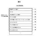
図2は、第2ストレージ12a内の論理デバイスを管理する論理デバイス管理情報126の構成例示図である。 FIG. 2 is a configuration example diagram of the logical device management information 126 for managing the logical devices in the
論理デバイス管理情報126としては、論理デバイス番号21、サイズ22、対応物理/外部デバイス番号23、デバイス状態24、ポートID/ターゲットID/LUN(Logical Unit number)25、接続ホスト名26、移行中物理/外部デバイス番号27、データ移行進捗ポインタ28、データ移行中フラグ29がある。 The logical device management information 126 includes
サイズ22には、当該論理デバイス、つまり論理デバイス番号21により特定される論理デバイスの容量が格納される。対応物理/外部デバイス番号23には、当該論理デバイスに対応する第2ストレージ装置12aの物理デバイスの番号、もしくは外部デバイス、すなわち第1ストレージ装置12bの論理デバイスの番号が格納される。物理/外部デバイス番号23が未割り当ての場合、当該エントリには無効値が設定される。このデバイス番号は、RAID管理情報127、もしくは外部デバイス管理情報のエントリ番号となる。デバイス状態24には、当該論理デバイスの状態を示す情報が設定される。状態としては、「オンライン」、「オフライン」、「未実装」、「障害オフライン」、「データ移行中」が存在する。「オンライン」は、当該論理デバイスが正常に稼動し、上位ホストからのアクセスが可能な状態であることを示す。「オフライン」は、当該論理デバイスは定義され、正常に稼動しているが、上位ホストからのアクセスはできない状態にあることを示す。この状態は、以前上位ホストで使用されていたが、上位ホストでそのデバイスが不要となって使われなくなった場合に相当する。なお、当該論理デバイスが定義されるとは、物理デバイスや外部デバイスとの対応関係が設定されることで、具体的には、物理/外部デバイス番号23が設定されることである。「未実装」は、当該論理デバイスが定義されておらず上位ホストからのアクセスはできない状態にあることを示す。「障害オフライン」は、当該論理デバイスに障害が発生して上位ホストからのアクセスができないことを示す。また、「データ移行中」は、外部デバイスからのデータ移行処理中、又は外部デバイスへのデータ移行処理中であることを示す。 The
なお、本実施形態では、簡単のため、利用可能な論理デバイスは製品の工場出荷時にあらかじめディスクユニット121上に作成された物理デバイスへ割り当てられているものとする。このため、利用可能な論理デバイスについては、工場出荷段階で、デバイス状態24の初期値は「オフライン」状態、その他は「未実装」状態となる。 In this embodiment, for the sake of simplicity, it is assumed that usable logical devices are assigned to physical devices created on the
エントリ25のポート番号には、当該論理デバイスが複数のポート123のうちのどのポートに接続されているかを表す情報が設定される。ポート番号としては、各ポート123にストレージ装置12内で一意に割り振った番号が用いられる。また、ターゲットIDとLUNは、論理デバイスを識別するための識別子である。ここでは、SCSI上でホスト計算機11からデバイスをアクセスする場合に、それぞれは、SCSI−ID、LUNとして用いられる。接続ホスト名26は、ファイバチャネルスイッチ18に接続されたストレージ装置12a,12bでのみ利用される情報で、当該論理デバイスにアクセスが許可されているホスト計算機11を識別するホスト名である。ホスト名としては、ホスト計算機11のインタフェース112に付与されたWWN(World Wide Name)など、ホスト計算機11もしくはインタフェース112を一意に識別可能なものであればよい。同ストレージ12a,12bの制御メモリには、このほかに、各ポート123のWWNなどの属性に関する管理情報が保持される。 In the port number of the
移行中物理/外部デバイス番号27には、デバイス状態24が「データ移行中」であるとき、当該論理デバイスが割り当てられた物理/外部デバイスの移行先物理/外部デバイス番号が保持される。データ移行進捗ポインタ28は、データ移行処理が未完了な移行元の領域の先頭アドレスを示す情報であり、データ移行の進行に伴い、更新される。データ移行中フラグ29は、初期値がOffで、On設定されると当該論理デバイスが割り当てられた物理/外部デバイスを別の物理/外部デバイスへデータ移行中であることを示し、この場合のみ本管理情報の移行中物理/外部デバイス番号27とデータ移行中進捗ポインタ28が有効となる。 The physical / external device number 27 during migration holds the physical / external device number of the physical / external device to which the logical device is assigned when the
図3は、ストレージ装置12a内の物理デバイスを管理するRAID管理情報127の構成例示図である。 FIG. 3 is a configuration example diagram of
RAID管理情報127としては、物理デバイス番号31、サイズ32、対応論理デバイス番号33、デバイス状態34、RAID構成35、ストライプサイズ36、ディスク番号リスト37、ディスク内開始オフセット38、ディスク内サイズ39がある。 The
サイズ32には、当該物理デバイス、つまり物理デバイス番号31により特定される物理デバイスの容量が格納される。対応論理デバイス番号33には、当該物理デバイスが対応する第2ストレージ装置12a内の論理デバイス番号が格納される。論理デバイスへ未割り当ての場合、当該エントリには無効値が設定される。デバイス状態34には、当該物理デバイスの状態を示す情報が設定される。状態としては、「オンライン」、「オフライン」、「未実装」、「障害オフライン」が存在する。「オンライン」は、当該物理デバイスが正常に稼動し、論理デバイスに割り当てられている状態であることを示す。「オフライン」は、当該物理デバイスは定義され、正常に稼動しているが、論理デバイスに未割り当てであることを示す。なお、物理デバイスが定義されるとは、ディスクユニット121との対応関係が設定されることで、具体的には、後述のディスク番号リスト37やディスク内開始オフセットが設定されることである。「未実装」は、当該物理デバイスがディスクユニット121上に定義されていない状態にあることを示す。「障害オフライン」は、当該物理デバイスに障害が発生して論理デバイスに割り当てられないことを示す。 The
なお、本実施形態では、簡単のため、物理デバイスは製品の工場出荷時にあらかじめディスクユニット121上に作成されているものとする。このため、利用可能な物理デバイスについては、工場出荷段階で、デバイス状態34の初期値は「オフライン」状態、その他は「未実装」状態となる。 In this embodiment, for simplicity, it is assumed that the physical device is created on the
RAID構成35には、当該物理デバイスが割り当てられたディスクユニット121のRAIDレベル、データディスクとパリティディスク数などRAID構成に関連する情報が保持される。同じように、ストライプサイズ36には、RAIDにおけるデータ分割単位(ストライプ)長が保持される。ディスク番号リスト37には、当該物理デバイスが割り当てられたRAIDを構成する1又は複数のディスクユニット121の番号が保持される。この番号はストレージ装置12内でディスクユニット121を識別するために付与した一意な値である。ディスク内開始オフセット37とディスク内サイズ38には、当該物理デバイスデータが各ディスクユニット121内のどの領域に割り当てられているかを示す情報である。本実施例では、簡単のため、RAIDを構成する各ディスクユニット121内のオフセットとサイズを統一している。 The
なお、以上で説明したRAID管理情報127の各項目は、いずれも、第2ストレージ装置12aの工場出荷段階で設定されている。 Each item of the
図4は、外部デバイスである第1ストレージ装置12bの論理デバイスを管理する第2ストレージ装置12aの外部デバイス管理情報128の構成例示図である。 FIG. 4 is a configuration example diagram of the external
外部デバイス管理情報128としては、外部デバイス番号41、サイズ42、対応論理デバイス番号43、デバイス状態44、ストレージ識別情報45、ストレージ内デバイス番号46、イニシエータポート番号リスト47、ターゲットポートID/ターゲットID/LUNリスト48がある。 External
外部デバイス番号41には、第1ストレージ装置12bの論理デバイスに割り当てた、第2ストレージ装置12a内で一意な値が保持される。サイズ42には、当該外部デバイス、つまり外部デバイス番号41により特定される外部デバイスの容量が格納されている。対応論理デバイス番号43には、当該外部デバイスが対応する第2ストレージ装置12a内の論理デバイス番号が格納される。論理デバイスへ未割り当ての場合、当該エントリには無効値が設定される。デバイス状態44には、当該外部デバイスの状態を示す情報が設定される。状態としては、「オンライン」、「オフライン」、「未実装」、「障害オフライン」が存在し、各状態の意味は、RAID管理情報127内のデバイス状態34と同じである。第2ストレージ装置12aの初期状態は他ストレージを接続していないため、デバイス状態44の初期値は「未実装」となる。 The external device number 41 holds a unique value in the
ストレージ識別情報45には、当該外部デバイスを搭載する第1ストレージ装置12bの識別情報が保持される。ストレージ識別情報としては、同ストレージ装置12bのベンダ識別情報と各ベンダが一意に割り振る製造シリアル番号の組み合わせ、などが考えられる。ストレージ内デバイス番号46には、当該外部デバイスに対応する第1ストレージ装置12b内の論理デバイス番号が保持される。イニシエータポート番号リスト47には、当該外部デバイスへアクセス可能な第2ストレージ装置12aのポート123bの番号のリストが保持される。ターゲットポートID/ターゲットID/LUNリスト48には、当該外部デバイスが第1ストレージ装置12bの1つ以上のポート123にLUN定義されている場合、それらのポート123のポートID、及び当該外部デバイスが割り当てられたターゲットID/LUNが1つ又は複数個保持される。 The
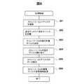
次に、本発明の実施形態で、第2ストレージ装置12aの導入に伴うストレージ管理者および計算機システムの動作について、図5に示すフローチャートに従って説明する。 Next, in the embodiment of the present invention, the operations of the storage administrator and the computer system accompanying the introduction of the
まず、ストレージ管理者は、第2ストレージ装置12aをファイバチャネルスイッチ18に接続する(ステップ501)。本実施形態では、ホスト計算機11からのアクセス用としてポート123aをファイバチャネルスイッチ18のポート181に接続し、第1ストレージ装置12bを含む他ストレージへのアクセス用としてポート123bをファイバチャネルスイッチ18のポート181に接続する。第2ストレージ装置12aが起動すると、ファイバチャネルスイッチ18は、第2ストレージ装置のポート123a,123bとのリンク確立を検出し、以降、ファイバチャネル規格に従い、各ポート123a,123bからスイッチ18へのログインが実行されると共に、ホスト計算機11や第2ストレージ装置12bの各インタフェースおよびポートへのログインが実行される。このとき、第2ストレージ装置12aでは、ポート123a,123bのそれぞれがログインしたホスト計算機11等のポートのWWNやIDなどの情報を保持することになる。ストレージマネージャ131の導入コントローラ134は、スイッチ18からの状態変更通知を受け、スイッチ18からネットワークトポロジ情報を再取得し、新規に第2ストレージ装置12aが登録されたことを検知する。 First, the storage administrator connects the
ステップ502以降の処理は、ストレージ管理者から、第2ストレージ装置12aの導入処理の開始指示を受けたストレージマネージャ131の導入コントーラ134及び第2ストレージ装置12aの導入コントローラ129が主として実行する処理である。ステップ502で、ストレージマネージャ131の導入コントローラ134は、スイッチ18のゾーニング設定を変更すると共に、第1ストレージ装置12bのデバイスアクセス権設定を変更し、第2ストレージ装置12aから第1ストレージ装置12bのデバイスにアクセス可能とする。 The processing after
ステップ503で、ストレージマネージャ131は、第1ストレージ装置12bの論理デバイスを第2ストレージ装置12aの論理デバイスへ割り当てる。具体的には、ストレージマネージャ131は、まず、第2ストレージ装置12aへの移行対象である第1ストレージ装置12bのポートIDリストを第2ストレージ装置12aに送信する。第2ストレージ装置12aの導入コントーラ129は、受信したリストにある第1ストレージ装置12bのポート123について特定のLUNを指定したSCSIのInquiryコマンドを全LUN分、ポート123bから送信する。これに対して、第1ストレージ装置12bのプロセッサは、第1ストレージ装置12bの各ポートIDに対して実際に設定されているLUNに対するInquiryコマンドに正常応答する。第2ストレージ装置12aの導入コントーラ129は、この応答により、アクセス可能でかつ第2ストレージ装置12aへ移行可能である第1ストレージ装置12bの論理デバイスを特定し、これらの論理デバイスに関する外部デバイスリスト(第2ストレージ装置12aにとっての外部デバイスリスト)を作成する。導入コントローラ129は、移行可否の判断には、第2ストレージ装置12aに接続されている装置の名、装置の種類、装置の容量等の情報を利用する。なお、装置名や装置の種類や装置の容量等の情報は、上記Inquiryコマンドに対する応答の返却情報、及びInquiryコマンドに続いて送信されるRead Capacityコマンドに対する応答の返却情報から取得される。導入コントローラ129は、移行可能と判断した第1ストレージ装置12bの論理デバイスを、第2ストレージ装置12aの外部デバイスとして、外部デバイス管理情報128へ登録する。具体的には、デバイス状態44が「未実装」である外部デバイスを見つけ出し、当該外部デバイスエントリに、情報42〜48を設定する。ここでデバイス状態44は「オフライン」に変更される。 In
第2ストレージ装置12aの導入コントローラ129は、指定されたポートについての前述の外部デバイスリストをストレージマネージャ131に通知し、ストレージマネージャ131の導入コントローラ134は、第2ストレージ装置12aに対して、第1ストレージ装置12bの論理デバイスの割付を指示する。第2ストレージ装置12aの導入コントローラ129は、この指示を受け付けると、第2ストレージ装置12aの未実装状態の論理デバイスaへ、外部デバイスa、すなわち第1ストレージ装置12bの論理デバイスを割り付ける。具体的には、第2ストレージ装置12aの導入コントローラ129は、論理デバイスaに関する論理デバイス管理情報126の対応物理/外部デバイス番号23に、第1ストレージ装置12bの論理デバイスが対応する外部デバイスaのデバイス番号41を設定し、論理デバイス管理情報126のデバイス状態24を「未実装」から「オフライン」に変更する。併せて、外部デバイス管理情報128のうち、対応論理デバイス番号43に論理デバイスaのデバイス番号21を設定し、デバイス状態44を「オンライン」に変更する。 The
続いて、ステップ504で、ストレージマネージャ131の導入コントローラ131は、第2ストレージ装置12aに割り当てた論理デバイスaに対してホスト計算機11からアクセス可能になるよう、ポート123aに対するLUNを定義するよう第2ストレージ装置12aに指示する。第2ストレージ装置12aの導入コントローラ129は、この指示を受けて、第2ストレージ装置12aのポート123aに対して、先に割り当てた論理デバイスaに関するLUNを定義する、すなわち、デバイスパスを定義する。そして、論理デバイス管理情報126のポート番号/ターゲットID/LUN25及び接続ホスト名26を設定する。 Subsequently, in
第1ストレージ装置12bの論理デバイスが第2ストレージ装置12aの論理デバイスとして割り当てられ、LUNも定義されたら、ストレージマネージャ131の導入コントーラ134は、ホスト計算機11のDLM111へ指示し、デバイスの再認識を行わせる。ホスト計算機11のDLM111は、この指示を受けて、新しく割り当てられた論理デバイスに関するデバイスファイルを作成する。例えば、ヒューレットパッカード社のUNIX(登録商標)オペレーティングシステムでは、"IOSCAN"コマンドにより、新規論理デバイスの認識、デバイスファイルの作成が行われる。DLM111では、新規に作成されたデバイスファイルに対応するストレージ装置12の論理デバイスが既に作成されているデバイスファイルと同一のものであれば、それを検知し、これらのデバイスファイルを同じグループとして管理する。この同一性の判定には、先述のInquiryコマンドなどにより、ストレージ12内のデバイス番号を取得する方法などが考えられる。しかし、第1ストレージ装置12b内の論理デバイスbに対応するものが第2ストレージ装置12a内の論理デバイスaである場合、これらの論理デバイスa,bがDLM111からは異なるストレージ装置12a,12bの論理デバイスとして見えるため、同一のグループには管理されない。 When the logical device of the
次に、ストレージマネージャ131の導入コントローラ134は、ホスト計算機11のDLM111に対して、アクセス先の変更を指示する。この指示を受けたDLM111は、第1ストレージ装置12b内のデバイスに対するアクセスを第2ストレージ装置12a内デバイスに対するアクセスに変更する(ステップ506)。具体的には、ストレージマネージャ131の導入コントーラ134は、まず、第1ストレージ装置12bと第2ストレージ装置12aのデバイス対応情報をDLM111に送信する。このデバイス対応情報は、第2ストレージ装置12bの論理デバイスの割り当てに関する情報である。ホスト計算機11のDLM111は、第1ストレージ装置12b内の論理デバイスbに関連するデバイスファイルグループに割り付けられた仮想デバイスファイルを、第2ストレージ装置12a内の論理デバイスaに関連するデバイスファイルグループに割り付ける。この結果、ホスト計算機11上で動作するソフトウェアにとっては、第1ストレージ装置12b内の論理デバイスbにアクセスする手順通りのままで、第2ストレージ装置12a内の論理デバイスaへアクセスすることが可能となる。 Next, the
次に、ステップ507で、ストレージマネージャ131の導入コントローラ134は、スイッチ18に対してゾーニング設定を変更させ、第1ストレージ装置12bに対してデバイスアクセス権設定を変更させ、ホスト計算機11からの第1ストレージ装置12bのデバイスへの直接アクセスを抑止する。 Next, in
次に、第2ストレージ装置12aが計算機システムに導入された後、第2ストレージ装置12a内の空きデバイスに、第1ストレージ装置12b内のデバイスに記憶されているデータを移行する処理について、図6に示すフローチャートに従って説明する。 Next, after the
まず、ストレージマネージャ131の導入コントローラ134から第2ストレージ装置12aへデータ移行指示を与える。第2ストレージ装置12aの導入コントローラ129は、ステップ601で、RAID管理情報127のデバイス状態34をチェックして、「オフライン」の状態、つまり空き状態の物理デバイスaを探索する。「オフライン」の物理デバイスを探索したら、サイズ32を参照して空きデバイスの容量を求める。次に、導入コントローラ129は、ステップ602で、外部デバイス管理情報128のデバイス状態44が「オフライン」で、外部デバイス管理情報128のサイズ42が当該物理デバイスaの容量に収まる外部デバイス(以下、移行対象デバイス)を探索する。 First, a data migration instruction is given from the
移行先の空き物理デバイスaと移行対象デバイスが決定したら、導入コントローラ129は、ステップ603で、第2ストレージ装置12aの論理デバイスaに空き状態の物理デバイスを割り当てる(ステップ603)。具体的には、物理デバイスaに対応するRAID管理情報127の対応論理デバイス番号33に論理デバイスaの番号を登録し、デバイス状態34を「オフライン」から「オンライン」に変更する。さらに、論理デバイスaに対応する論理デバイス管理情報126のデータ移行進捗ポインタ28を初期化した後、デバイス状態24を「データ移行中」に設定し、データ移行中フラグ29をOnに設定し、移行中物理/外部デバイス番号27に物理デバイスaの番号を設定する。 When the migration destination free physical device a and the migration target device are determined, the
デバイス割り当てが完了したら、第2ストレージ装置12aの導入コントローラ129は、ステップ604で、移行対象デバイスから物理デバイスaへのデータ移行処理を行う。具体的には、移行対象デバイスの先頭からデータをキャッシュメモリ124に読み上げ、物理デバイスaへ当該データを書き込み、これを移動対象デバイスの終端まで繰り返していく。この際、物理デバイスaへの書き込みが完了する毎に、論理デバイス管理情報126の論理デバイスaに関するデータ移行進捗ポインタ28に、次の移行対象領域の先頭アドレスを設定する。 When the device allocation is completed, the
全てのデータ転送が完了したら、導入コントーラ129は、ステップ605で、論理デバイス管理情報126の対応物理/外部デバイス番号23に物理デバイスaの物理デバイス番号を設定し、デバイス状態24を「データ移行中」から「オンライン」に変更し、データ移行中フラグ29をOffに設定し、移行中物理/外部デバイス番号27に無効値を設定する。さらに、移行対象デバイスに対応する外部デバイス管理情報128の対応論理デバイス番号43に無効値を、デバイス状態44に「オフライン」をそれぞれ設定する。 When all the data transfer is completed, the
次に、ホスト計算機11からの入出力要求に対する第2ストレージ装置12aの動作について、図7に示すフローチャートに従って説明する。 Next, the operation of the
第2ストレージ装置12aの導入コントローラ129は、ホスト計算機11からの入出力要求を受信すると(ステップ701)、当該要求がリードであるかライトであるかを判断する(ステップ702)。当該要求がリードの場合、キャッシュメモリ124に処理対象データが保持されている(ヒット)かをチェックし(ステップ703)、処理対象データが保持されていない場合にはキャッシュメモリ124へのデータステージングを行う。この際、論理デバイス管理情報126の該当論理デバイスに関するデバイス状態24でデータ移行中か否かを判定し、データ移行中であれば、論理デバイス管理情報126の該当論理デバイスに関するデータ移行進捗ポインタ28で、処理対象論理デバイスの処理対象アドレスがデータ移行済み領域であるかを判定する(ステップ704)。データ移行中ではあるが処理対象領域がデータ移行済みである場合は、移行中物理/外部デバイス番号27で示される移行先デバイスからのリード処理を行い(ステップ706)、それ以外の場合は、対応物理/外部デバイス番号23で示される移行対象デバイスからのリード処理を行う(ステップ705)。 When receiving the input / output request from the host computer 11 (step 701), the
なお、ステップ705でのリード処理の際、導入コントローラ129は、ホスト計算機11からのリード要求を、対応物理/外部デバイス番号23で示される移行対象デバイスへのリード要求に変換して、これを第1ストレージ装置12bに送信する。第1ストレージ装置12bは、このリード要求を受信すると、前述の移行対象デバイスに対応するディスクユニット121に対してリード処理して、このリード内容を第2ストレージ装置12aへ送信する。また、ステップ706でのリード処理の際には、第2ストレージ装置12aの移行中物理/外部デバイス番号27で示される移行先デバイスに対してリード処理する。 At the time of the read process in
リード処理実行(ステップ705,706)後、キャッシュメモリ124へのデータステージングが完了すると、キャッシュメモリ124に保持した対象データをホスト計算機11へデータ転送する(ステップ707)。そして、第2ストレージ装置12aのディスクコントローラ122は、ホスト計算機11へ完了報告を送信する(ステップ708)。 When the data staging to the
また、ステップ703で、キャッシュヒットしたと判断した場合には、即、キャッシュメモリ124に保持した対象データをホスト計算機11へデータ転送する(ステップ707)。 If it is determined in
第2ストレージ装置12aのディスクコントローラ122は、ホスト計算機11へのデータ転送が終了すると、ホスト計算機11に処理完了報告を送信する(ステップ708)。 When the data transfer to the
ステップ702で、ホスト計算機11からの入出力要求がライトであると判断した場合、第2ストレージ装置12aのディスクコントローラ122は、キャッシュメモリ124にライトデータ格納領域を割り当て、ホスト計算機11からキャッシュメモリ124へライトデータを転送し、ホスト計算機11へ完了報告を送信する(ステップ709〜711)。その後、当該ライトデータのデステージングを行う。 If it is determined in
このデステージングの際、論理デバイス管理情報126のデバイス状態24で、当該論理デバイスがデータ移行中か否かを判定し(ステップ712)、データ移行中であれば、移行元(移行対象)/移行先の両方のデバイスへ当該データのライト処理を行い(ステップ713)、データ移行中でなければ、対応物理/外部デバイス番号23で示される移行対象デバイスへ当該データのライト処理を行う(ステップ714)。 At the time of destaging, it is determined whether or not the logical device is undergoing data migration in the
次に、第2ストレージ装置12aにディスクユニット121を増設した際のデータ移行処理について、図8に示すフローチャートに従って説明する。 Next, data migration processing when the
まず、ストレージ管理者が第2ストレージ装置12aへディスクユニット121を増設し、第2ストレージ装置12aの導入コントローラ129がこの増設を検知すると(ステップ801)、新たな空きデバイス、すなわちオフライン状態の物理デバイスを定義する(ステップ802)。この際、RAID管理情報127の32〜39が更新される。 First, the storage administrator adds the
以降、新規に割り当てられた空きデバイスに対して、未移行な外部デバイスをデータ移行する(ステップ803〜806)。これらの処理(ステップ803〜806)は、図6のステップ602〜605の処理と同様の処理を同一であるため、繰り返し説明しない。 Thereafter, the unmigrated external device is migrated to the newly assigned free device (
以上、本発明に係る実施形態について説明したが、本発明は上記の実施形態に限定されず、その要旨の範囲内で数々の変形が可能である。 As mentioned above, although embodiment which concerns on this invention was described, this invention is not limited to said embodiment, Many deformation | transformation are possible within the range of the summary.
例えば、図5のフローチャートで説明した計算機システムへの第2ストレージ装置12aの導入処理では、ステップ503で、ストレージマネージャ131から第2ストレージ装置12aに対して、移行対象となる第1ストレージ装置12bのポートIDリストを送信しているが、このポートIDリストの替わりに、第1ストレージ装置12bを特定可能な情報、例えばInquiryコマンドで取得可能な装置名などの識別情報リストを送信してもよい。同リストの識別情報は、ストレージマネージャ131が第1ストレージ装置12bを管理する上で必要な情報であり、基本的には内部に保持しているが、リスト送信時に新たな第1ストレージ装置12bに対してInquiryコマンドを送信して取得してもよい。その場合、第2ストレージ装置12aは、ポート123bから到達可能な全ストレージノードポートに対してInquiryコマンドを送信して、第1ストレージ装置12bから得られた情報のうちの装置識別情報と前述の識別情報リストとを比較して、一致するポートのみを移行対象とする。また、第2ストレージ装置12aは、ストレージマネージャ131から指示をもらわずに、ポート123bから到達可能なポート、すなわちノードポートログインが可能な全ストレージノードポートを移行対象としてもよい。 For example, in the process of introducing the
また、第2ストレージ装置12aの導入処理中のステップ503で、第2ストレージ装置12aが検出した外部デバイスリストをストレージマネージャ131に通知し、ストレージマネージャ131から指示された外部デバイスのみを移行対象としているが、第2ストレージ装置12aは、検出した外部デバイスリストをストレージマネージャ131に通知せず、この外部デバイスリストが示す全ての外部デバイスを移行対象としてもよい。 In
また、ステップ503で、第2ストレージ装置12aは、ストレージマネージャ131から指示された外部デバイスに対して未実装な論理デバイスを選択して割り当てているが、ストレージマネージャ131で割当対象の未実装な論理デバイスを決定して、これを第2ストレージ装置12aに指示してもよい。その場合、ストレージマネージャ131は、図2の論理デバイス管理情報126のうち、論理デバイス番号21、デバイス状態24等の情報を第2ストレージ装置12aから取得して、この情報を元に移動対象を決定する必要がある。 In
また、図6のフローチャートで説明した、第2ストレージ装置12bの論理デバイスに割り当てた第1ストレージ装置12bの論理デバイス、すなわち外部デバイスの第2ストレージ装置12の空き物理デバイスへの移行処理では、ステップ601で、第2ストレージ装置12aが全ての空き物理デバイスを移行先として、外部デバイスからのデータ移行を行っているが、移行対象可否の判定可能な制御情報を元に移動先物理デバイスを限定してもよい。具体的には、図3に示すRAID管理情報にデータ移行対象可否フラグを設け、このフラグに、物理デバイス初期設定時や増設時に各物理デバイスをデータ移行先としてよいか否かを示すフラグ値を設定し、この情報を元に第2ストレージ装置12aは移行先としてよい物理デバイスを特定する。なお、同フラグ値は、図1で示していない第2ストレージ装置12aの構成管理端末、若しくはストレージマネージャ131に設けられたキーボードやマウス等の入出力装置により、ストレージ管理者が設定する。フラグ値の設定例としては、物理デバイス導入時の基本設定値を「移行対象不可」と自動設定し、必要に応じてストレージ管理者が特定物理デバイスに関する同フラグ値を「移行対象可能」に変更する形態でもよいし、基本設定値を「移行対象可能」と自動設定し、ストレージ管理者が特定物理デバイスに関する同フラグ値を「移行対象不可」に変更する形態でもよい。 Further, in the migration processing described in the flowchart of FIG. 6 to the logical device of the
また、ストレージマネージャ131からのデータ移行指示に関して、ストレージマネージャ131が、図3に示すRAID管理情報127のうち、物理デバイス番号31、サイズ32、デバイス状態34等の物理デバイス情報を保持し、データ移行先となる空き物理デバイスを第2ストレージ装置12aに指定するようにしてもよい。その場合、第2ストレージ装置12aの当該データ移行処理(図6に示す)では、指定された物理デバイスが空きであるかをチェックし、空きでない場合にはデータ移行要求を拒否するステップを追加する必要がある。 Further, regarding the data migration instruction from the
また、図6に示すステップ602の処理で、第2ストレージ装置12aが移行対象外部デバイスを決定する際、ステップ601で選択した空き物理デバイスのサイズに収まるかどうかだけをチェックして外部デバイスを決定しているが、当該外部デバイスの他の情報を元に移動対象を決定してもよい。例えば、図4で示す外部デバイス管理情報128にデータ移行対象可否フラグを設け、当該フラグ値で移行対象可否を判定してもよい。この場合、ステップ503で、外部デバイスに関する外部デバイス管理情報128を登録する際に、当該フラグに移行可もしくは移行不可を示す値を初期設定し、以降、ストレージ管理者が当該フラグ値を変更する。このストレージ管理者によるフラグ値変更には、図1に示していない第2ストレージ装置12aの構成管理端末、若しくはストレージマネージャ131に設けられたキーボードやマウス等の入出力装置等を用いる。また、このデータ移行対象可否フラグの替わりに、データ移行対象優先度情報を設けてもよい。この場合、第2ストレージ装置12aは、ストレージ管理者により設定された移行対象優先度を考慮して、移行対象外部デバイスを決定する。 Further, in the process of
また、移行対象外部デバイス決定基準として、例えば、当該外部デバイスへのホストアクセス統計情報を利用してもよい。具体的には、第2ストレージ装置12aにおいて、各論理デバイス毎のアクセス統計情報を取得する。図9にアクセス統計情報の例を示す。アクセス統計情報のうち、アクセス回数91は、当該論理デバイスへの単位時間当たりのアクセス回数を示し、リード回数92は、当該論理デバイスへの単位時間当たりのリード回数を示している。当該論理デバイスへのライト回数は、以上のアクセス回数91とリード回数92とから算出できる。リードキャッシュヒット率93、ライトキャッシュヒット率94は、それぞれ、リードアクセス時の第2ストレージ装置12aのキャッシュメモリ124でのヒット率、ライトアクセス時の第2ストレージ装置12aのキャッシュメモリ124でのヒット率を示す。これらの情報を組み合わせることで、各論理デバイス毎の対応する外部デバイス(第1ストレージ装置12bのデバイス)へのアクセス頻度を算出することができる。そこで、ここでは、以上のように得られた各外部デバイスへのアクセス頻度から、よりアクセス頻度の高い外部デバイスで、且つ空きデバイスサイズで収容可能なものをデータ移行対象とする。 Further, as access target external device determination criteria, for example, host access statistical information for the external device may be used. Specifically, access statistical information for each logical device is acquired in the
また、図6で示す当該データ移行処理では、ストレージマネージャ131から第2ストレージ装置12aに対してデータ移行を指示しているが、第1ストレージ装置12aの論理デバイス、すなわち外部デバイスを第2ストレージ装置12bの論理デバイスに対応づけた処理での延長で、第1ストレージ装置12aが当該データ移行処理を自動実行しても構わない。つまり、ストレージマネージャ131の導入コントローラ134の各種機能のうち、図6で示すデータ移行処理関連部分を第2ストレージ装置12aに搭載してもよい。 In the data migration process shown in FIG. 6, the
11…ホスト計算機、12…ストレージ装置、12a…第2ストレージ装置、12b…第1ストレージ装置、13…管理サーバ、18…ファイバチャネルスイッチ、112…インタフェース、113…ネットワークインターフェース、121…ディスクユニット、129…第2ストレージ装置の導入コントローラ、122…ディスクコントローラ、123…ポート、125…ネットワークインタフェース、131…ストレージマネージャ、133…ネットワークインタフェース、134…管理サーバの導入コントローラ、181…ポート、182…ネットワークインタフェース、142…IPネットワーク。
DESCRIPTION OF
Claims (14)
Translated fromJapanese前記ホスト計算機及び前記第1ストレージ装置に対して、情報の入出力が可能に、前記第2のストレージ装置を接続し、
前記第2ストレージ装置から前記第1ストレージ装置に対してアクセス可能に、該第1ストレージ装置のアクセス権を設定変更し、
前記第1ストレージ装置の一以上の前記記憶デバイスに関する論理デバイス(以下、第1論理デバイスとする)を前記第2ストレージ装置の論理デバイス(以下、第2論理デバイスとする)に割り付け、
前記ホスト計算機から前記第2のストレージ装置の前記第2論理デバイスに対してアクセス可能に、該第2論理デバイスに関するパス定義と該ホスト計算機でのデバイス認識とを行い、
前記ホスト計算機から前記第1ストレージ装置の一以上の記憶デバイスへの入出力処理を、前記第2ストレージ装置へ要求するよう、該ホスト計算機の入出力設定を変更する、
ことを特徴とするストレージ装置の導入方法。A storage apparatus for newly introducing a second storage apparatus having one or more storage devices into a computer system comprising a first storage apparatus having one or more storage devices and a host computer that accesses the first storage apparatus In the introduction method of
The second storage device is connected to the host computer and the first storage device so that information can be input and output.
Changing the access right of the first storage device so that the second storage device can access the first storage device;
Allocating logical devices (hereinafter referred to as first logical devices) related to one or more storage devices of the first storage device to logical devices (hereinafter referred to as second logical devices) of the second storage device;
A path definition related to the second logical device and device recognition in the host computer are performed so that the host computer can access the second logical device of the second storage device;
Changing input / output settings of the host computer so as to request the second storage device to perform input / output processing from the host computer to one or more storage devices of the first storage device;
A method for introducing a storage device.
前記ホスト計算機から前記第1ストレージ装置の一以上の記憶デバイスへの入出力処理を抑止するよう、該第1ストレージ装置のアクセス権を変更する、
ことを特徴とするストレージ装置の導入方法。The storage apparatus introduction method according to claim 1,
Changing the access right of the first storage device so as to suppress input / output processing from the host computer to one or more storage devices of the first storage device;
A method for introducing a storage device.
前記第1ストレージ装置の前記第1論理デバイスを前記第2ストレージ装置の前記第2論理デバイスとして、前記ホスト計算機に見せかけている状態で、
前記第1ストレージ装置の1以上の前記記憶デバイスに記憶されているデータのうち、全データ又は一部のデータを前記第2ストレージ装置の1以上の前記記憶デバイスに移行し、
データの移行後、当該データに関して、前記ホスト計算機から前記第2ストレージ装置の前記第2論理デバイスへの入出力要求を、該第2ストレージ装置のデータ移行済みの前記記憶デバイスへの入出力要求として処理する、
ことを特徴とするストレージ装置の導入方法。In the introduction method of the storage apparatus according to any one of claims 1 and 2,
With the first logical device of the first storage device pretending to the host computer as the second logical device of the second storage device,
Of the data stored in the one or more storage devices of the first storage device, all or part of the data is transferred to the one or more storage devices of the second storage device,
After data migration, with respect to the data, an input / output request from the host computer to the second logical device of the second storage device is used as an input / output request to the storage device to which data has been migrated of the second storage device. Process,
A method for introducing a storage device.
前記第2ストレージ装置は、前記ホスト計算機から前記第2論理デバイスへのリード要求を受信すると、該リード要求が該第2ストレージ装置への未移行分のデータを対象にしているときには、該リード要求を前記第1論理デバイスへのリード要求に変換して、前記第1ストレージ装置へ送信して、該第1ストレージ装置に、前記第1論理デバイスに対応する前記記憶デバイスに対してリード処理させ、
前記第2ストレージ装置は、前記ホスト計算機から前記第2論理デバイスへの前記リード要求が前記第2ストレージ装置への移行済み分のデータを対象にしているときには、該第2ストレージ装置の前記記憶デバイスに対してリード処理する、
ことを特徴とするストレージ装置の導入方法。The storage apparatus introducing method according to claim 3,
When the second storage device receives a read request from the host computer to the second logical device, the read request is directed to data that has not been transferred to the second storage device. Is converted into a read request to the first logical device and is sent to the first storage device to cause the first storage device to read the storage device corresponding to the first logical device,
When the read request from the host computer to the second logical device targets data that has been transferred to the second storage device, the second storage device stores the storage device of the second storage device Lead processing,
A method for introducing a storage device.
前記第1ストレージ装置の一以上の前記記憶デバイス(以下、第1論理デバイスとする)に関する論理デバイスを前記第2のストレージ装置の論理デバイス(以下、第2論理デバイスとする)に割り付ける論理デバイス割付ステップと、
前記ホスト計算機から前記第2のストレージ装置の前記第2論理デバイスに対してアクセス可能に、該第2論理デバイスに関するパス定義を行うパス定義ステップと、
を実行させることを特徴とするストレージ装置の導入プログラム。When a second storage apparatus having one or more storage devices is newly introduced into a computer system having a first storage apparatus having one or more storage devices and a host computer that accesses the first storage apparatus In the storage apparatus introduction program for operating the second storage apparatus,
Logical device allocation for allocating logical devices related to one or more storage devices (hereinafter referred to as first logical devices) to the logical devices (hereinafter referred to as second logical devices) of the second storage device. Steps,
A path definition step for defining a path for the second logical device so that the host computer can access the second logical device of the second storage device;
An installation program for a storage apparatus, characterized in that
前記第2ストレージ装置から前記第1ストレージ装置に対してアクセス可能に、該第1ストレージ装置に、該第1ストレージ装置のアクセス権を設定変更させるステップと、
前記ホスト計算機から前記第1ストレージ装置の一以上の記憶デバイスへの入出力処理を抑止するよう、該第1ストレージ装置に、該第1ストレージ装置のアクセス権を変更させるステップと、
を実行させることを特徴とするストレージ装置の導入プログラム。In the storage apparatus installation program according to claim 5,
Causing the first storage device to change the access right of the first storage device so that the second storage device can access the first storage device;
Causing the first storage device to change the access right of the first storage device so as to inhibit input / output processing from the host computer to one or more storage devices of the first storage device;
An installation program for a storage apparatus, characterized in that
前記ホスト計算機から前記第1ストレージ装置の一以上の記憶デバイスへの入出力処理を、前記第2ストレージ装置へ要求するよう、該ホスト計算機に、該ホスト計算機の入出力設定を変更させる、
ことを特徴とするストレージ装置の導入プログラム。In the storage apparatus installation program according to any one of claims 5 and 6,
Causing the host computer to change input / output settings of the host computer so as to request the second storage device to perform input / output processing from the host computer to one or more storage devices of the first storage device;
A storage apparatus installation program characterized by the above.
前記第1ストレージ装置の1以上の前記記憶デバイスに記憶されているデータのうち、全データ又は一部のデータを前記第2ストレージ装置の1以上の前記記憶デバイスに移行するデータ移行ステップと、
データの移行後、当該データに関して、前記ホスト計算機から前記第2ストレージ装置の前記第2論理デバイスへの入出力要求を、該第2ストレージ装置のデータ移行済みの前記記憶デバイスへの入出力要求として処理する入出力要求先変更ステップと、
を実行させることを特徴とするストレージ装置の導入プログラム。In the storage apparatus installation program according to any one of claims 5 to 7,
A data migration step of migrating all or part of data stored in one or more storage devices of the first storage device to one or more storage devices of the second storage device;
After data migration, with respect to the data, an input / output request from the host computer to the second logical device of the second storage device is used as an input / output request to the storage device to which data has been migrated of the second storage device. I / O request destination change step to be processed;
An installation program for a storage apparatus, characterized in that
前記ホスト計算機から前記第2論理デバイスへのリード要求を受信するリード要求受信ステップと、
前記リード要求受信ステップで受信した前記リード要求が前記第2ストレージ装置への未移行分のデータを対象にしているときには、該リード要求を前記第1論理デバイスへのリード要求に変換して、前記第1ストレージ装置へ送信して、該第1ストレージ装置に、前記第1論理デバイスに対応する前記記憶デバイスに対してリード処理させるリード処理指示ステップと、
前記リード要求受信ステップで受信した前記リード要求が前記第2ストレージ装置への移行済み分のデータを対象にしているときには、該第2ストレージ装置の前記記憶デバイスに対してリード処理するリード処理ステップと、
を実行させることを特徴とするストレージ装置の導入プログラム。In the storage apparatus installation program according to claim 8,
A read request receiving step of receiving a read request from the host computer to the second logical device;
When the read request received in the read request receiving step is for data that has not been migrated to the second storage device, the read request is converted into a read request to the first logical device, and A read processing instruction step for transmitting to the first storage device and causing the first storage device to perform read processing on the storage device corresponding to the first logical device;
When the read request received in the read request receiving step is for data transferred to the second storage device, a read processing step for performing read processing on the storage device of the second storage device; ,
An installation program for a storage apparatus, characterized in that
前記ホスト計算機から前記第2論理デバイスへのライト要求を受信するライト要求受信ステップと、
前記ライト要求受信ステップで受信した前記ライト要求が前記第2ストレージ装置への移行中のデータを対象にしているときには、該ライト要求を前記第1論理デバイスへのライト要求に変換して、前記第1ストレージ装置へ送信して、該第1ストレージ装置に、前記第1論理デバイスに対応する前記記憶デバイスに対してライト処理させると共に、前記データの移行先である前記第2ストレージ装置の前記記憶デバイスに対してライト処理するライト処理ステップと、
を実行させることを特徴とするストレージ装置の導入プログラム。In the storage apparatus installation program according to any one of claims 8 and 9,
A write request receiving step of receiving a write request from the host computer to the second logical device;
When the write request received in the write request reception step targets data that is being transferred to the second storage device, the write request is converted into a write request to the first logical device, and the first The storage device of the second storage device that is the data migration destination while sending to the first storage device and causing the first storage device to write to the storage device corresponding to the first logical device A light processing step for performing light processing on
An installation program for a storage apparatus, characterized in that
前記第2ストレージ装置に1以上の記憶デバイスが増設されたことを検知する増設検知ステップと、
前記増設検知ステップで、1以上の前記記憶デバイスが増設されたことを検知すると、該記憶デバイスに対して論理デバイスを設定するデバイス定義ステップと、
前記第1ストレージ装置の1以上の前記記憶デバイスに記憶されているデータのうちの一部のデータを、前記デバイス定義ステップで論理デバイスが設定された前記第2ストレージ装置の1以上の前記記憶デバイスに移行するデータ移行ステップと、
データの移行後、当該データに関して、前記ホスト計算機から前記第2ストレージ装置の前記第2論理デバイスへの入出力要求を、該第2ストレージ装置のデータ移行済みの前記記憶デバイスへの入出力要求として処理する入出力要求先変更ステップと、
を実行させることを特徴とするストレージ装置の導入プログラム。In the storage apparatus installation program according to any one of claims 5 to 10,
An addition detection step of detecting that one or more storage devices are added to the second storage device;
A device definition step of setting a logical device for the storage device when detecting that one or more storage devices are added in the addition detection step;
One or more of the storage devices of the second storage device in which a part of the data stored in the one or more storage devices of the first storage device is set as a logical device in the device definition step Data migration steps to migrate to
After data migration, with respect to the data, an input / output request from the host computer to the second logical device of the second storage device is used as an input / output request to the storage device to which data has been migrated of the second storage device. I / O request destination change step to be processed;
An installation program for a storage apparatus, characterized in that
前記第1ストレージ装置に対して、前記第2ストレージ装置から前記第1ストレージ装置に対してアクセス可能に、該第1ストレージ装置のアクセス権を設定変更させるステップと、
前記第2ストレージ装置に対して、前記第1ストレージ装置の一以上の前記記憶デバイス(以下、第1論理デバイスとする)に関する論理デバイスを前記第2ストレージ装置の論理デバイス(以下、第2論理デバイスとする)に割り付けさせる割付指示ステップと、
前記ホスト計算機から前記第2のストレージ装置の前記第2論理デバイスに対してアクセス可能に、該第2ストレージ装置に対して該第2論理デバイスに関するパス定義を行わせると共に、該ホスト計算機に対してデバイス認識を行わせる定義指示ステップと、
前記ホスト計算機に対して、前記ホスト計算機から前記第1ストレージ装置の一以上の記憶デバイスへの入出力処理を、前記第2ストレージ装置へ要求するよう、該ホスト計算機の入出力設定を変更させる入出力変更指示ステップと、
前記第1ストレージ装置に対して、前記ホスト計算機から前記第1ストレージ装置の一以上の記憶デバイスへの入出力処理を抑止するよう、該第1ストレージ装置のアクセス権を変更させるステップと、
を実行させることを特徴とするストレージ装置の導入プログラム。When a second storage apparatus having one or more storage devices is newly introduced into a computer system having a first storage apparatus having one or more storage devices and a host computer that accesses the first storage apparatus In the installation program of the storage device that operates the management device that manages each device,
Changing the access rights of the first storage device so that the first storage device is accessible from the second storage device to the first storage device;
For the second storage device, a logical device related to one or more storage devices (hereinafter referred to as first logical devices) of the first storage device is referred to as a logical device (hereinafter referred to as second logical device) of the second storage device. Allocation instruction step to be allocated, and
The host computer is allowed to define a path for the second logical device so that the second logical device of the second storage device can be accessed from the host computer, and the host computer Definition instruction step for device recognition,
An input for changing the input / output setting of the host computer so that the host computer requests the second storage device to perform input / output processing from the host computer to one or more storage devices of the first storage device. An output change instruction step;
Changing the access right of the first storage device so as to inhibit the input / output processing of the first storage device from the host computer to one or more storage devices of the first storage device;
An installation program for a storage apparatus, characterized in that
前記計算機システムを構成する複数の機器のうち、前記ホスト計算機を除くいずれかの機器から、該ホスト計算機の入出力設定を変更させる旨の指示を受け付ける変更指示受付ステップと、
前記変更指示受付ステップで、前記指示を受け付けると、前記ホスト計算機から前記第1ストレージ装置の一以上の記憶デバイスへの入出力処理を、前記第2ストレージ装置へ要求するよう、該ホスト計算機の入出力設定を変更する入出力変更ステップと、
を実行させることを特徴とするストレージ装置の導入プログラム。When a second storage apparatus having one or more storage devices is newly introduced into a computer system having a first storage apparatus having one or more storage devices and a host computer that accesses the first storage apparatus In the introduction program of the storage device for operating the host computer,
A change instruction receiving step for receiving an instruction to change the input / output setting of the host computer from any one of the plurality of devices constituting the computer system, excluding the host computer;
When the instruction is accepted in the change instruction accepting step, the host computer is input so as to request the second storage device to perform input / output processing from the host computer to one or more storage devices of the first storage device. An input / output change step to change the output setting;
An installation program for a storage apparatus, characterized in that
1以上の記憶デバイスと、
前記第1ストレージ装置の一以上の前記記憶デバイス(以下、第1論理デバイスとする)に関する論理デバイスを当該ストレージ装置の論理デバイス(以下、第2論理デバイスとする)に割り付ける論理デバイス割付手段と、
前記ホスト計算機から当該ストレージ装置の前記第2論理デバイスに対してアクセス可能に、該第2論理デバイスに関するパス定義を行うパス定義手段と、
を備えていることを特徴とするストレージ装置。
In a storage apparatus newly introduced into a computer system comprising a first storage apparatus having one or more storage devices and a host computer that accesses the first storage apparatus,
One or more storage devices;
Logical device allocation means for allocating logical devices related to one or more of the storage devices (hereinafter referred to as first logical devices) to logical devices (hereinafter referred to as second logical devices) of the storage device;
Path definition means for defining a path for the second logical device so that the host computer can access the second logical device of the storage apparatus;
A storage apparatus comprising:
Priority Applications (1)
| Application Number | Priority Date | Filing Date | Title |
|---|---|---|---|
| JP2006006067AJP4643456B2 (en) | 2006-01-13 | 2006-01-13 | How to set up access |
Applications Claiming Priority (1)
| Application Number | Priority Date | Filing Date | Title |
|---|---|---|---|
| JP2006006067AJP4643456B2 (en) | 2006-01-13 | 2006-01-13 | How to set up access |
Related Parent Applications (1)
| Application Number | Title | Priority Date | Filing Date |
|---|---|---|---|
| JP2003008821ADivisionJP2004220450A (en) | 2003-01-16 | 2003-01-16 | Storage device, its introduction method, and its introduction program |
Publications (3)
| Publication Number | Publication Date |
|---|---|
| JP2006155640Atrue JP2006155640A (en) | 2006-06-15 |
| JP2006155640A5 JP2006155640A5 (en) | 2007-02-22 |
| JP4643456B2 JP4643456B2 (en) | 2011-03-02 |
Family
ID=36633778
Family Applications (1)
| Application Number | Title | Priority Date | Filing Date |
|---|---|---|---|
| JP2006006067AExpired - Fee RelatedJP4643456B2 (en) | 2006-01-13 | 2006-01-13 | How to set up access |
Country Status (1)
| Country | Link |
|---|---|
| JP (1) | JP4643456B2 (en) |
Cited By (4)
| Publication number | Priority date | Publication date | Assignee | Title |
|---|---|---|---|---|
| JP2010198420A (en)* | 2009-02-26 | 2010-09-09 | Fujitsu Ltd | Storage control device, storage control method, and storage control program |
| JP2012088817A (en)* | 2010-10-15 | 2012-05-10 | Toshiba Corp | Data processing system, data movement method, and data movement program |
| US8443160B2 (en) | 2010-08-06 | 2013-05-14 | Hitachi, Ltd. | Computer system and data migration method |
| US9292211B2 (en) | 2011-03-02 | 2016-03-22 | Hitachi, Ltd. | Computer system and data migration method |
Families Citing this family (1)
| Publication number | Priority date | Publication date | Assignee | Title |
|---|---|---|---|---|
| JP6005566B2 (en) | 2013-03-18 | 2016-10-12 | 株式会社東芝 | Information processing system, control program, and information processing apparatus |
- 2006
- 2006-01-13JPJP2006006067Apatent/JP4643456B2/ennot_activeExpired - Fee Related
Cited By (5)
| Publication number | Priority date | Publication date | Assignee | Title |
|---|---|---|---|---|
| JP2010198420A (en)* | 2009-02-26 | 2010-09-09 | Fujitsu Ltd | Storage control device, storage control method, and storage control program |
| US8443160B2 (en) | 2010-08-06 | 2013-05-14 | Hitachi, Ltd. | Computer system and data migration method |
| US8892840B2 (en) | 2010-08-06 | 2014-11-18 | Hitachi, Ltd. | Computer system and data migration method |
| JP2012088817A (en)* | 2010-10-15 | 2012-05-10 | Toshiba Corp | Data processing system, data movement method, and data movement program |
| US9292211B2 (en) | 2011-03-02 | 2016-03-22 | Hitachi, Ltd. | Computer system and data migration method |
Also Published As
| Publication number | Publication date |
|---|---|
| JP4643456B2 (en) | 2011-03-02 |
Similar Documents
| Publication | Publication Date | Title |
|---|---|---|
| US7177991B2 (en) | Installation method of new storage system into a computer system | |
| JP4568574B2 (en) | Storage device introduction method, program, and management computer | |
| JP4813385B2 (en) | Control device that controls multiple logical resources of a storage system | |
| US7480780B2 (en) | Highly available external storage system | |
| US7269646B2 (en) | Method for coupling storage devices of cluster storage | |
| US7228380B2 (en) | Storage system that is connected to external storage | |
| US7613896B2 (en) | Storage area dynamic assignment method | |
| US8103826B2 (en) | Volume management for network-type storage devices | |
| US8402220B2 (en) | Storage controller coupled to storage apparatus | |
| JP4993928B2 (en) | Storage system, storage area release method, and storage system | |
| US7171522B2 (en) | Storage system including storage adaptors having cache memories and grasping usage situation of each cache memory and equalizing usage of cache memories | |
| US7908433B2 (en) | Virtual volume control method involving device stop | |
| US20080184000A1 (en) | Storage module and capacity pool free capacity adjustment method | |
| JP2010003061A (en) | Computer system and method for changing i/o configuration thereof | |
| JP2007072538A (en) | Device control takeover method for storage virtualization apparatus | |
| JP2003345631A (en) | Computer system and storage area allocation method | |
| JP4643456B2 (en) | How to set up access |
Legal Events
| Date | Code | Title | Description |
|---|---|---|---|
| RD02 | Notification of acceptance of power of attorney | Free format text:JAPANESE INTERMEDIATE CODE: A7422 Effective date:20061114 | |
| A521 | Written amendment | Free format text:JAPANESE INTERMEDIATE CODE: A523 Effective date:20070110 | |
| A871 | Explanation of circumstances concerning accelerated examination | Free format text:JAPANESE INTERMEDIATE CODE: A871 Effective date:20070110 | |
| A975 | Report on accelerated examination | Free format text:JAPANESE INTERMEDIATE CODE: A971005 Effective date:20070117 | |
| RD04 | Notification of resignation of power of attorney | Free format text:JAPANESE INTERMEDIATE CODE: A7424 Effective date:20070208 | |
| A131 | Notification of reasons for refusal | Free format text:JAPANESE INTERMEDIATE CODE: A131 Effective date:20070320 | |
| A521 | Written amendment | Free format text:JAPANESE INTERMEDIATE CODE: A523 Effective date:20070521 | |
| A131 | Notification of reasons for refusal | Free format text:JAPANESE INTERMEDIATE CODE: A131 Effective date:20070918 | |
| A521 | Written amendment | Free format text:JAPANESE INTERMEDIATE CODE: A523 Effective date:20071119 | |
| A131 | Notification of reasons for refusal | Free format text:JAPANESE INTERMEDIATE CODE: A131 Effective date:20080108 | |
| A521 | Written amendment | Free format text:JAPANESE INTERMEDIATE CODE: A523 Effective date:20080306 | |
| A02 | Decision of refusal | Free format text:JAPANESE INTERMEDIATE CODE: A02 Effective date:20080527 | |
| A521 | Written amendment | Free format text:JAPANESE INTERMEDIATE CODE: A523 Effective date:20080724 | |
| A911 | Transfer of reconsideration by examiner before appeal (zenchi) | Free format text:JAPANESE INTERMEDIATE CODE: A911 Effective date:20080731 | |
| A912 | Removal of reconsideration by examiner before appeal (zenchi) | Free format text:JAPANESE INTERMEDIATE CODE: A912 Effective date:20090522 | |
| A01 | Written decision to grant a patent or to grant a registration (utility model) | Free format text:JAPANESE INTERMEDIATE CODE: A01 | |
| A61 | First payment of annual fees (during grant procedure) | Free format text:JAPANESE INTERMEDIATE CODE: A61 Effective date:20101202 | |
| R150 | Certificate of patent or registration of utility model | Free format text:JAPANESE INTERMEDIATE CODE: R150 | |
| FPAY | Renewal fee payment (event date is renewal date of database) | Free format text:PAYMENT UNTIL: 20131210 Year of fee payment:3 | |
| LAPS | Cancellation because of no payment of annual fees |