JP2006151125A - On-vehicle image processing device - Google Patents
On-vehicle image processing deviceDownload PDFInfo
- Publication number
- JP2006151125A JP2006151125AJP2004342950AJP2004342950AJP2006151125AJP 2006151125 AJP2006151125 AJP 2006151125AJP 2004342950 AJP2004342950 AJP 2004342950AJP 2004342950 AJP2004342950 AJP 2004342950AJP 2006151125 AJP2006151125 AJP 2006151125A
- Authority
- JP
- Japan
- Prior art keywords
- image processing
- radar
- processing area
- vehicle
- area
- Prior art date
- Legal status (The legal status is an assumption and is not a legal conclusion. Google has not performed a legal analysis and makes no representation as to the accuracy of the status listed.)
- Pending
Links
Images


Classifications
- G—PHYSICS
- G01—MEASURING; TESTING
- G01S—RADIO DIRECTION-FINDING; RADIO NAVIGATION; DETERMINING DISTANCE OR VELOCITY BY USE OF RADIO WAVES; LOCATING OR PRESENCE-DETECTING BY USE OF THE REFLECTION OR RERADIATION OF RADIO WAVES; ANALOGOUS ARRANGEMENTS USING OTHER WAVES
- G01S13/00—Systems using the reflection or reradiation of radio waves, e.g. radar systems; Analogous systems using reflection or reradiation of waves whose nature or wavelength is irrelevant or unspecified
- G01S13/86—Combinations of radar systems with non-radar systems, e.g. sonar, direction finder
- G01S13/867—Combination of radar systems with cameras
- G—PHYSICS
- G01—MEASURING; TESTING
- G01S—RADIO DIRECTION-FINDING; RADIO NAVIGATION; DETERMINING DISTANCE OR VELOCITY BY USE OF RADIO WAVES; LOCATING OR PRESENCE-DETECTING BY USE OF THE REFLECTION OR RERADIATION OF RADIO WAVES; ANALOGOUS ARRANGEMENTS USING OTHER WAVES
- G01S17/00—Systems using the reflection or reradiation of electromagnetic waves other than radio waves, e.g. lidar systems
- G01S17/86—Combinations of lidar systems with systems other than lidar, radar or sonar, e.g. with direction finders
- G—PHYSICS
- G06—COMPUTING OR CALCULATING; COUNTING
- G06T—IMAGE DATA PROCESSING OR GENERATION, IN GENERAL
- G06T7/00—Image analysis
- G06T7/70—Determining position or orientation of objects or cameras
- G—PHYSICS
- G06—COMPUTING OR CALCULATING; COUNTING
- G06T—IMAGE DATA PROCESSING OR GENERATION, IN GENERAL
- G06T7/00—Image analysis
- G06T7/70—Determining position or orientation of objects or cameras
- G06T7/73—Determining position or orientation of objects or cameras using feature-based methods
Landscapes
- Engineering & Computer Science (AREA)
- Radar, Positioning & Navigation (AREA)
- Remote Sensing (AREA)
- Physics & Mathematics (AREA)
- General Physics & Mathematics (AREA)
- Theoretical Computer Science (AREA)
- Computer Vision & Pattern Recognition (AREA)
- Computer Networks & Wireless Communication (AREA)
- Electromagnetism (AREA)
- Radar Systems Or Details Thereof (AREA)
- Traffic Control Systems (AREA)
- Optical Radar Systems And Details Thereof (AREA)
- Image Analysis (AREA)
- Image Processing (AREA)
- Closed-Circuit Television Systems (AREA)
Abstract
Description
Translated fromJapanese本発明は、車外監視手段としてのレーダと撮像手段を有する車載システムに関する。 The present invention relates to an in-vehicle system having a radar as an outside vehicle monitoring unit and an imaging unit.
車両の先行車追従自動走行機能等を実現するためには、先行車や障害物などの物体を識別してその位置情報などを取得することが必要であり、そのための車外監視手段としては、レーダ(レーザレーダやミリ波レーダなど)や撮像手段(CCDカメラやCMOSカメラなど)が用いられる。このうちレーダは、物体までの距離や方位を測定することは比較的高速かつ精度良く可能であるが、物体が何であるか(先行車なのか障害物なのかなど)を正確に判定できないという欠点を持つ。一方、撮像手段は、周知の画像処理によって撮影された画像内に存在するものが何であるかを推定することが可能であるが、画像処理に時間がかかり、十分な応答性(リアルタイム性)を得ることが困難であるという欠点を持つ。
そこで、特許文献1や特許文献2に見られるように、レーダと撮像手段を併用し、レーダの測定結果に基づいて、撮像手段により得られた画像における特定の領域(物体が存在すると推定される領域、以下、画像処理エリアという)を決定し、この領域のみについて画像処理を行う画像処理装置が提案されている。In order to realize a vehicle's preceding vehicle following automatic traveling function, it is necessary to identify an object such as a preceding vehicle or an obstacle and acquire its position information, etc. (Laser radar, millimeter wave radar, etc.) and imaging means (CCD camera, CMOS camera, etc.) are used. Of these, radar can measure the distance and direction to an object relatively quickly and with high accuracy, but it cannot accurately determine what the object is (such as a preceding vehicle or an obstacle). have. On the other hand, the imaging means can estimate what is present in an image captured by well-known image processing. However, it takes time for image processing, and sufficient responsiveness (real time) is obtained. It has the disadvantage of being difficult to obtain.
Therefore, as seen in
ところが、上述した従来の画像処理装置は、以下のような解決すべき問題点を有する。
まず、特許文献1の装置では、当該特許文献1の段落[0030]の式によって、画像処理を行なう基準点及びエリアを算出しているが、検出された物体の大きさや形状に応じて画像処理エリアが算出されているとはいえず、予め想定された縦横比率に応じて画像設定エリアを算出していることになる。したがって、想定外の形状又は大きさの物体が存在した場合、適切な画像処理エリアを設定できないという問題がある。例えば、自動車を想定していると、人や自転車或いはバイク等に対しては、画像処理エリアが大きくなりすぎてしまい、不適切になる。However, the above-described conventional image processing apparatus has the following problems to be solved.
First, in the apparatus of
また特許文献1には、物体との距離に応じて画像処理エリアのサイズを設定することが記載されているが、自車の直前に自転車などが存在した場合においては、ほぼ全画面が画像処理エリアとなり、合理的とはいえない。また、同じ距離に異なる物体(例えば、大型トラックと自転車)が存在する場合においては、同じ大きさの画像処理エリアを設定してしまうことになり、適切な画像処理エリアを設定できない(何れか一方については、大きすぎるエリアを設定したり、小さすぎるエリアを設定してしまったりする)問題がある。
なお、特許文献1の装置は、水平方向にのみスキャンするレーザレーダを用いている。従って、路面の勾配による前方物体の検出漏れを防止するため、上下方向に長いレーザビームを用いる必要がある。この構成であれば、水平方向の分解能を高く設定することはできるが、上下方向の分解能は低くならざるを得ず、物体からの反射があった場合、実質的にレーザレーダの検知範囲内のどこに物体が存在するかを上下方向については判別することはできない。このため、検出漏れを防止するためには、上下方向については画像処理エリアを特に大きく設定せざるを得ず、画像処理エリアが不適切になる程度が著しい。 Note that the apparatus of
次に、特許文献2の装置は、上下左右にスキャンする2次元スキャン方式のレーザレーダを用いており、レーダの測定結果において、距離のデータが同一である測定点が存在する上下左右方向の領域を、物体が存在する領域と判定し、この領域の大きさにある適当な値を掛けることによって物体よりも大きな領域(物体及び物体の周辺を含む領域)を設定し、この領域を画像処理エリアとしている。
このため、この特許文献2の装置では、レーザレーダによって物体が存在する領域を上下及び左右方向について判定すべく、レーダを2次元スキャンするとともに、レーザレーダの発光頻度(レーダの分解能)を上下左右の両方向について相当に高める必要があり、レーダの動作或いは測定データの処理に時間がかかり、リアルタイム処理が困難になる、さらには、消費電力も増えてしまうという問題がある。Next, the apparatus of
For this reason, the apparatus of
そこで本発明は、車外監視手段としてのレーダと撮像手段を有する車載システムにおいて、撮像手段により得られた画像における画像処理すべき領域(画像処理エリア)を、レーダの測定結果に基づいて適切に設定できる車載用画像処理装置であって、分解能の高いレーダを必要としない車載用画像処理装置を提供することを目的としている。 Accordingly, the present invention appropriately sets an area (image processing area) to be subjected to image processing in an image obtained by the imaging means in an in-vehicle system having radar and imaging means as an outside monitoring means based on the measurement result of the radar. It is an object of the present invention to provide an in-vehicle image processing apparatus that does not require a high-resolution radar.
本願の車載用画像処理装置は、車外に走査しつつ出力した電磁波の反射波に基づいて車外に存在する物体までの距離と方位を測定するレーダと、車外の画像を取得するための撮像手段と、この撮像手段により得られる画像中の所定の画像処理エリアについて画像処理を行う画像処理手段と、を備えた車載用画像処理装置において、
前記レーダによって検出された物体の測定位置に応じて、前記画像処理エリアの中心位置を決定し、前記レーダから出力される電磁波のビームプロファイルに応じて、前記画像処理エリアの大きさを決定する画像処理エリア決定手段を設けたものである。An in-vehicle image processing apparatus according to the present application includes a radar that measures a distance and an azimuth to an object existing outside a vehicle based on a reflected wave of an electromagnetic wave output while scanning outside the vehicle, and an imaging unit that acquires an image outside the vehicle. In an in-vehicle image processing apparatus comprising: an image processing unit that performs image processing on a predetermined image processing area in an image obtained by the imaging unit;
An image for determining the center position of the image processing area according to the measurement position of the object detected by the radar, and for determining the size of the image processing area according to the beam profile of the electromagnetic wave output from the radar Processing area determination means is provided.
ここで、「ビームプロファイル」とは、ビームの伝搬方向に直交する断面における二次元方向の拡がりを意味し、具体的には、ビームの径、断面積、或いは拡がり角などである。また、「レーダによって検出された物体の測定位置」とは、物体が存在するとして検出された測定点の座標(上下左右前後の3次元の位置情報)を意味し、具体的には、しきい値を越える反射波が受信された時の例えば送信ビームの中心軸位置であり、距離方向については、その時の送信から反射波受信までの遅延時間により計算される距離の位置である。なお、この測定位置は、レーダの分解能に対する物体の大きさによっては、一つの物体に対して走査方向に複数存在する。一般の自動車に対しては、この測定位置が複数検出されるように、一般的な車幅に対して十分小さい走査分解能が設定されるのが通常である。
また「レーダ」は、二方向に走査(スキャン)を行う二次元スキャン方式が望ましいが、一方向にのみ走査を行う一次元スキャン方式でもよい。Here, the “beam profile” means a two-dimensional divergence in a cross section orthogonal to the beam propagation direction, and specifically, a beam diameter, a cross-sectional area, or an divergence angle. The “measurement position of the object detected by the radar” means the coordinates of the measurement point detected as the presence of the object (three-dimensional position information in the vertical and horizontal directions), specifically, the threshold. For example, the position of the center axis of the transmission beam when a reflected wave exceeding the value is received, and the distance direction is the position of the distance calculated by the delay time from the transmission at that time to reception of the reflected wave. Note that a plurality of measurement positions exist in the scanning direction with respect to one object depending on the size of the object with respect to the resolution of the radar. For a general automobile, a sufficiently small scanning resolution is generally set for a general vehicle width so that a plurality of measurement positions are detected.
The “radar” is preferably a two-dimensional scanning method that performs scanning in two directions, but may be a one-dimensional scanning method that performs scanning only in one direction.
本願の車載用画像処理装置によれば、物体が存在するとして検出された測定位置を中心として、レーダのビーム断面に応じた拡がりをもつ領域が、画像処理エリアとして決定される。また、物体がレーダの走査方向にある程度の大きさを持つ場合には、上記測定位置は走査方向に複数存在し、それに対応して画像処理エリアも複数決定される。
このため、ビーム断面の拡がりを適度に設定すれば、決定された画像処理エリア全体(複数ある場合には、これらの集合)は、少なくとも走査方向においては、物体の大きさにかかわらず物体とその周辺を適度に含む適切な領域となる。例えば、人や自転車のように比較的小さな物体の場合には、上記測定位置の数が少なくなり、その分だけ画像処理エリアが走査方向に狭くなる。一方、例えば通常の自動車や大型トラックのように比較的大きな物体の場合には、上記測定位置の数がその大きさに応じて多くなり、その分だけ画像処理エリアが走査方向に広くなる。なお、このように画像処理エリアが適切な大きさになる効果は、二次元スキャン方式のレーダを使用した場合には、両方向について得られる。According to the in-vehicle image processing apparatus of the present application, an area having an extent corresponding to the beam cross section of the radar with the measurement position detected as the presence of an object as a center is determined as the image processing area. When the object has a certain size in the scanning direction of the radar, there are a plurality of measurement positions in the scanning direction, and a plurality of image processing areas are determined correspondingly.
For this reason, if the spread of the beam cross section is set appropriately, the entire determined image processing area (a set of these if there are a plurality of images) is the object and its object regardless of the size of the object, at least in the scanning direction. It becomes an appropriate area including the periphery moderately. For example, in the case of a relatively small object such as a person or a bicycle, the number of measurement positions is reduced, and the image processing area is narrowed in the scanning direction accordingly. On the other hand, in the case of a relatively large object such as a normal automobile or a large truck, the number of measurement positions increases according to the size, and the image processing area becomes wider in the scanning direction. The effect that the image processing area is appropriately sized in this way can be obtained in both directions when a two-dimensional scan type radar is used.
また、本願の車載用画像処理装置によれば、上述したようにビーム断面の拡がりに応じて画像処理エリアを決定するため、物体の大きさ自体をレーダによって正確に判定しなくてもよい。このため、二次元スキャン方式のレーダを使用する場合でも、特許文献2の装置のようにレーダの分解能を各方向について高める必要がなく、高い応答性や省エネ性が実現できる。 Further, according to the in-vehicle image processing apparatus of the present application, since the image processing area is determined according to the spread of the beam cross section as described above, it is not necessary to accurately determine the size of the object itself by the radar. For this reason, even when a two-dimensional scanning radar is used, it is not necessary to increase the resolution of the radar in each direction unlike the apparatus of
次に、本願発明の好ましい態様は、レーダによって検出された物体の測定位置が複数あり、これら測定位置がレーダの分解能以下又は分解能近くに接近している場合には、画像処理エリア決定手段が、これらの測定位置を同一物体のものとしてグループ化し、これら測定位置に基づく画像処理エリアを一つの画像処理エリアとして統合する態様である。この場合、同一物体の画像処理エリアが統合され、物体を個々に識別するための画像処理が容易になる利点がある。 Next, according to a preferred aspect of the present invention, when there are a plurality of measurement positions of the object detected by the radar, and these measurement positions are close to or below the resolution of the radar, the image processing area determination means includes: In this aspect, these measurement positions are grouped as those of the same object, and image processing areas based on these measurement positions are integrated as one image processing area. In this case, there is an advantage that the image processing areas of the same object are integrated, and the image processing for individually identifying the object becomes easy.
また、本願発明の好ましい別の態様は、前記電磁波のビームの断面形状が、円形又は楕円形であることを特徴とするものである。
また、本願発明の好ましい別の態様は、前記電磁波のビームの拡がり角が、何れの方向についても、撮像手段の画角に比べて小さいことを特徴とするものである。この場合、画像処理エリアを、何れの方向についても、撮像手段により得られる画像よりも小さく制限することが可能となり、画像処理の負担を減らす効果が顕著になる。In another preferred aspect of the present invention, the cross-sectional shape of the electromagnetic wave beam is a circle or an ellipse.
In another preferred embodiment of the present invention, the divergence angle of the electromagnetic wave beam is smaller than the angle of view of the imaging means in any direction. In this case, the image processing area can be limited to be smaller than the image obtained by the imaging unit in any direction, and the effect of reducing the burden of image processing becomes significant.
また、本願発明の好ましい別の態様は、前記画像処理エリア決定手段が、自車が走行する路面に平行な平面を仮定し、前記レーダによって検出された物体の測定位置を前記平面に投影し、この投影された位置を2点以上結んでなる線を画像座標に変換し、この変換後の線によって前記画像処理エリアの下限を限定することを特徴とするものである。この場合、上下方向に走査を行わない一次元スキャン方式のレーダを使用して、上下方向のビームの拡がりを検出漏れがないように十分広く設定した場合でも、画像処理エリアの下限を必要最小限に制限することができ、画像処理エリアの上下方向の無用な拡がりを制限して、それによる画像処理の負担増を回避できる。
なお、自車から見た物体(先行車等)の高さ方向の位置は、路面の形状に依存する。自車と物体間で標高差が存在したとしても、二車が平面の傾いた路面上に存在するのであれば、上記平面の位置を補正することなく上記態様によって画像処理エリアの下限を適度な設定することができる。しかし、自車が水平な路面上に存在し、物体が斜面上に存在する場合は、車両から物体を見ると高い位置(もしくは、低い位置)に見えるため、上記平面の高さ方向の位置を補正する必要がある。そしてこの補正は、次のような方法により可能である。自車の位置はGPS(全地球測位システム)によって求めることが出来る。また、物体の位置は自車との相対位置から求めることが出来る。これらの現在位置に基づいて、道路地図情報を検索することにより斜度情報を知ることができる。これにより、相対的に、自車から物体が上下のどの位置に見えるかを求めることができ、この結果に応じて上記平面の高さ方向の位置を補正することによって、正しく画像処理エリアの下限を求めることが出来る。また、GPSを用いるのではなく、画像処理により路上の白線などの形状変化から路面の上下変化を求めることが出来るので、同様に自車と物体との相対的な上下位置関係を求めることが出来る。
また上記態様の場合、前記画像処理手段が、前記変換後の線に接する位置から画像処理のラスタスキャンを開始する態様とすることが望ましい。このようにすると、物体の下部位置から画像処理を開始することになり、物体をより早く画像処理によって識別できる。In another preferred aspect of the present invention, the image processing area determining means assumes a plane parallel to the road surface on which the vehicle travels, and projects the measurement position of the object detected by the radar onto the plane. A line formed by connecting two or more projected positions is converted into image coordinates, and the lower limit of the image processing area is limited by the converted line. In this case, even if a one-dimensional scanning radar that does not scan in the vertical direction is used and the beam spread in the vertical direction is set wide enough so that no detection is missed, the lower limit of the image processing area is minimized. It is possible to restrict the image processing area from being unnecessarily expanded in the vertical direction, thereby avoiding an increase in the burden of image processing.
The position in the height direction of an object (such as a preceding vehicle) viewed from the own vehicle depends on the shape of the road surface. Even if there is an altitude difference between the host vehicle and the object, if the two cars are on a sloping road surface, the lower limit of the image processing area is appropriately set by the above mode without correcting the position of the plane. Can be set. However, if the vehicle is on a horizontal road surface and the object is on a slope, it will look high when the object is viewed from the vehicle. It is necessary to correct. This correction is possible by the following method. The position of the vehicle can be obtained by GPS (Global Positioning System). Further, the position of the object can be obtained from the relative position to the own vehicle. Based on these current positions, the slope information can be obtained by searching the road map information. Accordingly, it can be relatively determined where the object is seen from the top and bottom from the own vehicle, and by correcting the position in the height direction of the plane according to this result, the lower limit of the image processing area is correctly set. Can be requested. In addition, since the vertical change of the road surface can be obtained from the shape change such as the white line on the road by image processing instead of using the GPS, the relative vertical position relationship between the own vehicle and the object can be obtained similarly. .
In the case of the above aspect, it is desirable that the image processing means start the raster scan of the image processing from a position in contact with the converted line. In this way, image processing starts from the lower position of the object, and the object can be identified earlier by image processing.
また、本願発明の好ましい別の態様は、前記画像処理エリア決定手段が、前記レーダから出力される電磁波のビーム強度が最大値の半分となる位置に応じて、前記画像処理エリアの大きさを決定するものである。これは、ビーム断面の拡がり(外縁)をどこに設定するかの態様であり、ビーム強度が最大値の半分となる位置(或いはその近傍)を、ビーム断面の外縁とするものである。ビーム強度は、中心から外側に向かって当然低下する傾向にあるが、例えばビーム強度がゼロとなる位置を外縁としたのでは、画像処理エリアがあまりに広くなり、画像処理エリアをあまり最適なものとすることができないが、半分程度のところであれば、より最適な大きさとすることができる。 In another preferred aspect of the present invention, the image processing area determining means determines the size of the image processing area according to a position where the beam intensity of the electromagnetic wave output from the radar is half of the maximum value. To do. This is an aspect of setting the spread (outer edge) of the beam cross section, and the position (or the vicinity thereof) at which the beam intensity becomes half of the maximum value is set as the outer edge of the beam cross section. The beam intensity tends to decrease naturally from the center toward the outside. For example, if the position where the beam intensity is zero is set as the outer edge, the image processing area becomes too wide, and the image processing area is not optimal. However, if it is about half, the size can be more optimal.
また、本願発明の好ましい別の態様は、前記画像処理エリア決定手段が、レーダによって検出された物体までの距離が増加するのに応じて、画像処理エリアの大きさを小さくするものである。具体的には、例えば画像処理エリアの大きさを決めるビームプロファイル(ビームの径、断面積、或いは拡がり角)を距離の増加に応じて小さく設定するものである。この態様であると、物体までの距離が離れても、画像処理エリアを必要最小限の最適な大きさとすることができる。遠方からの反射光はビーム中心の強度が高いところからしか返ってこなくなり、物体はビームのより中心側に存在するようになるからである。 In another preferred aspect of the present invention, the image processing area determination means reduces the size of the image processing area as the distance to the object detected by the radar increases. Specifically, for example, the beam profile (beam diameter, cross-sectional area, or divergence angle) that determines the size of the image processing area is set to be smaller as the distance increases. According to this aspect, even if the distance to the object is increased, the image processing area can be set to the minimum necessary optimum size. This is because the reflected light from far away returns only from the place where the intensity at the center of the beam is high, and the object comes to be closer to the center of the beam.
また、本願発明の好ましい別の態様は、レーダと撮像手段の中心軸のなす角度に応じて、画像処理エリアの位置を補正する画像処理エリア位置補正手段を備えるものである。この態様であると、レーダと撮像手段の中心軸が平行でないときでも、適正な位置に画像処理エリアを設定できる。 Further, another preferred aspect of the present invention includes image processing area position correcting means for correcting the position of the image processing area in accordance with the angle formed by the radar and the central axis of the imaging means. With this aspect, the image processing area can be set at an appropriate position even when the center axis of the radar and the imaging means is not parallel.
また、本願発明の好ましい別の態様は、前記画像処理エリア決定手段が、レーダから出力される電磁波の円形又は楕円系のビーム断面形状に、内接又は外接する矩形領域として、前記画像処理エリアを決定することを特徴とするものである。この態様であると、画像処理エリアが矩形であるため、画像処理エリアの設定が容易になる。
なおこの場合、前記画像処理エリア決定手段が、前記矩形領域の対角に位置する二つの角位置によって、前記画像処理エリアを特定する態様が望ましい。このようにすれば、前記画像処理エリアを特定するための処理データ量が少なくてすむという利点がある。According to another preferable aspect of the present invention, the image processing area determining means sets the image processing area as a rectangular area that is inscribed or circumscribed to a circular or elliptical beam cross-sectional shape of an electromagnetic wave output from a radar. It is characterized by determining. In this aspect, since the image processing area is rectangular, the image processing area can be easily set.
In this case, it is desirable that the image processing area determination unit specifies the image processing area by using two corner positions that are located diagonally to the rectangular area. This has the advantage that the amount of processing data for specifying the image processing area can be reduced.
本発明の車載用画像処理装置によれば、画像処理エリアを物体の大きさにかかわらず適切に設定できるとともに、分解能の高いレーダを必要とせず、高い応答性や省エネ性が実現できる。 According to the in-vehicle image processing apparatus of the present invention, an image processing area can be set appropriately regardless of the size of an object, and a high response and energy saving can be realized without requiring a high resolution radar.
以下、本発明の実施の形態を図面に基づいて説明する。
(第1形態例)
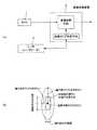
図1(a)は、本例の車載用画像処理装置を含む車外監視システムの構成を説明するブロック図、図1(b)はレーザレーダの投光ビーム断面等を説明する図である。また図2(a)は、レーザレーダの投光ビームとスキャンの方向を示す平面図であり、図2(b)は、レーザレーダの投光ビームを示す側面図である。Hereinafter, embodiments of the present invention will be described with reference to the drawings.
(First embodiment)
FIG. 1A is a block diagram for explaining a configuration of a vehicle exterior monitoring system including an in-vehicle image processing apparatus of this example, and FIG. 1B is a diagram for explaining a cross section of a projection beam of a laser radar. FIG. 2 (a) is a plan view showing the light projection beam of the laser radar and the scanning direction, and FIG. 2 (b) is a side view showing the light projection beam of the laser radar.
まず、全体構成について説明する。
本システムは、図1(a)に示すように、カメラ1(撮像手段)と、レーザレーダ(L/R)2と、画像処理装置3(画像処理エリア決定手段、画像処理手段)とを備える。
レーザレーダ2は、水平方向に走査を行う一次元スキャン方式のレーザレーダであり、自車の前方に向けて水平に搭載されている(図4参照)。このレーダ2の投光ビームは、図1(b)に示す如く断面が縦長の楕円形状であり、図2に示すように、その横拡がり角αは縦拡がり角βよりも格段に小さい。また、レーダ2の投光ビームの横拡がり角αも縦拡がり角βも、撮像手段であるカメラ1の画角(視野)に比べて格段に小さい(図13(a)参照)。なお、ビーム拡がり角αとβ(即ち、ビーム断面の拡がり)は、ビーム強度の断面方向の分布をガウス分布(正規分布)と仮定し、その分布における例えば3σ(σは標準偏差)までの範囲として定義される。
次にカメラ1は、例えばCCD又はCMOSなどの周知のデバイスよりなる撮像手段であり、この場合、1個だけ設置されている。またカメラ1は、例えば自車前方の画像が得られるように、自車の前方に向けて略水平に搭載される(図4参照)。なお、カメラ1とレーザレーダ2の中心軸(光軸)は、相互に平行であることが望ましいが、平行でなくてもよい。First, the overall configuration will be described.
As shown in FIG. 1A, this system includes a camera 1 (imaging means), a laser radar (L / R) 2, and an image processing device 3 (image processing area determining means, image processing means). .
The
Next, the
画像処理装置3は、マイクロコンピュータ(以下、マイコンという)を含む回路よりなり、レーザレーダ2を制御し、レーザレーダ2の測定結果から、カメラ1により得られる画像中の特定の領域(画像処理エリア)を決定し、この画像処理エリアについて画像処理を行うことによって、車両前方の物体判別等を行って、その情報を車両の他のコントローラに出力するものである。
以下、この画像処理装置3が実行する処理を、図7のフローチャート等を参照しつつ説明する。The image processing apparatus 3 includes a circuit including a microcomputer (hereinafter referred to as a microcomputer), controls the
Hereinafter, processing executed by the image processing apparatus 3 will be described with reference to the flowchart of FIG.
図7に示すように、画像処理装置3は、まず、ステップS1において、レーザビームスキャン、即ちレーザレーダ2による1回の走査分の測定動作を行う。
次いでステップS2では、ステップS1のレーダ2の測定動作によって検出された物体の測定位置(N個の測距ポイント)のデータを一つ取得する。具体的には、測距ポイントの座標Ci(H、YLi、ZLi)のデータを一つ取得する(N個のうちの一つを取得する)。ここで、Hは、図4に示すX方向(上下方向)の座標値であり、レーダ2の投光ビームの中心軸の高さに相当する値である。また、YLiは、図4に示すY方向(左右方向)の座標値であり、しきい値を超える反射光が受信された際の走査角度に基づいて求められる。また、ZLiは、図4に示すZ方向(前後方向、距離方向)の座標値であり、しきい値を超える反射光が受信された際の発光からの遅延時間に基づいて求められる。なお、この座標Ciに相当する画像上の位置は、画像処理エリアの中心位置とされる。As shown in FIG. 7, the image processing apparatus 3 first performs a laser beam scan, that is, a measurement operation for one scan by the
Next, in step S2, one piece of data of the measurement position (N distance measuring points) of the object detected by the measurement operation of the
次にステップS3で、予め設定されたビーム拡がり角αとβ(例えば、強度分布が3σの位置)から、ステップS2で求めた測定位置の距離ZLiにおけるビーム断面の径a,bを、数1に示す式によって計算する。なお、ビーム断面の径a,bは、図5(a)に示すように、ビーム断面の外縁に相当する楕円の短軸の半分の長さaと、長軸の半分の長さbである。なお、図1(b)に示すように、ビーム断面の拡がりを、ガウス分布の3σの半分の幅(半値幅)をもつ楕円とし、この楕円から上記径a,bを求めてもよい。 Next, in step S3, from the beam divergence angles α and β set in advance (for example, the position where the intensity distribution is 3σ), the diameters a and b of the beam cross section at the distance ZLi of the measurement position obtained in step S2 are expressed as Calculate with the formula shown in. As shown in FIG. 5 (a), the diameters a and b of the beam cross section are a length a half of the minor axis of the ellipse corresponding to the outer edge of the beam section and a length b of the half of the major axis. . As shown in FIG. 1 (b), the beam cross section may be an ellipse having a half width (half width) of 3σ of the Gaussian distribution, and the diameters a and b may be obtained from this ellipse.

次いでステップS4では、ステップS2で求めた測距ポイントの座標Ciを中心とする楕円(ステップS3で求めた径a,bの楕円)に外接する矩形領域を画像処理エリアとして、この矩形領域を特定する位置を取得する。この場合、前記矩形領域の対角に位置する二つの角位置、即ち、左上座標Ai(H+b、YLi−a、ZLi)と、右下座標Bi(H−b、YLi+a、ZLi)とを求める。なお、左下座標と右上座標を求めてもよいことはいうまでもない。また、外接でなく、内接する矩形領域を画像処理エリアとして求めてもよい。 Next, in step S4, the rectangular area circumscribing the ellipse centered on the coordinate Ci of the distance measurement point obtained in step S2 (the ellipses having the diameters a and b obtained in step S3) is specified as an image processing area, and this rectangular area is specified. Get the position to do. In this case, two corner positions located diagonally to the rectangular area, that is, an upper left coordinate Ai (H + b, YLi−a, ZLi) and a lower right coordinate Bi (H−b, YLi + a, ZLi) are obtained. Needless to say, the lower left coordinates and the upper right coordinates may be obtained. In addition, a rectangular area that is inscribed instead of the circumscribed area may be obtained as the image processing area.
次にステップS5では、ステップS2及びS4で得られた座標Ci,Ai,Bi(L/R座標系)をカメラ座標系(Xc、Yc、Zc)に変換し、その後ステップS6で、さらに画像座標系(U、V)に変換する。
なお、図4や図5(b)に示すように、各座標系の符号と方向の関係を定めた場合、L/R(XL、YL、ZL)とカメラ座標系(Xc、Yc、Zc)と画像座標系(U、V)の間には、次の数2及び数3に示す関係式が成り立つ。上記座標変換は、この関係式を用いて行う。数2において、Rは3×3の行列、Tは3×1の行列を表す。また、RとTは、周知のカメラキャリブレーションで予め設定しておく。また数3において、Fはカメラ1の焦点距離、U0,V0は画像中心、dU,dVは1画素の各方向の長さである。Next, in step S5, the coordinates Ci, Ai, Bi (L / R coordinate system) obtained in steps S2 and S4 are converted into the camera coordinate system (Xc, Yc, Zc), and then in step S6, further image coordinates are converted. Convert to system (U, V).
As shown in FIGS. 4 and 5B, when the relationship between the sign and direction of each coordinate system is determined, L / R (XL, YL, ZL) and camera coordinate system (Xc, Yc, Zc) And the image coordinate system (U, V), the following relational expressions are established: The coordinate transformation is performed using this relational expression. In
次にステップS7では、全ての測距ポイントの座標Ci(i=0、…、N−1)のデータについてステップS2〜S6の処理が完了であればステップS8に進み、そうでなければステップS2に戻り、次の測距ポイントについてステップS2〜S6の処理を繰り返す。
次にステップS8では、同一距離にある測距ポイント(距離ZLiのデータが所定の許容誤差範囲内で略同じである測距ポイント)を、同一物体のものとしてグループ化する(一つのグループとして関連付ける)。但しここでは、同一距離であっても、測定位置が前記レーダの分解能以下又は分解能近くに接近している場合にのみ、それら測定位置をグループ化する。例えば、投光ビームの横方向(Y方向)の分解能(単位はラジアン)に距離データを乗算して得られた間隔に対して、測定位置の横方向の間隔が等しいか小さいときに、それら特定位置の上記グループ化を行う。なお、測定位置の横方向の間隔が分解能に等しいか、小さい場合であっても、距離ZLiが所定の許容誤差範囲を越えている場合は、別のグループとして扱う。Next, in step S7, if the processing of steps S2 to S6 is completed for the data of the coordinates Ci (i = 0,..., N−1) of all the distance measurement points, the process proceeds to step S8. Returning to step S2, the processes in steps S2 to S6 are repeated for the next distance measuring point.
Next, in step S8, distance measurement points that are at the same distance (range distance points at which the data of the distance ZLi are substantially the same within a predetermined allowable error range) are grouped as those of the same object (associated as one group). ). However, here, even when the distance is the same, the measurement positions are grouped only when the measurement positions are close to or below the resolution of the radar. For example, when the horizontal distance of the measurement position is equal to or smaller than the distance obtained by multiplying the resolution (unit: radians) in the horizontal direction (Y direction) of the projected beam by the distance data, these are specified. Perform the above grouping of positions. Even if the horizontal interval between the measurement positions is equal to or smaller than the resolution, if the distance ZLi exceeds the predetermined allowable error range, it is handled as another group.
次にステップS9では、ステップS1でグループ化した各測定位置に基づく前記画像処理エリアを一つの画像処理エリアとして統合する。具体的には、統合された画像処理エリアを特定するデータとして、統合されたエリアの左上座標と右下座標を求める。ここで、左上座標は、複数あるグループ化された左上座標Aiのうちで最も左上の座標であり、右下座標は、複数あるグループ化された左上座標Biのうちで最も右下の座標である。 In step S9, the image processing areas based on the measurement positions grouped in step S1 are integrated as one image processing area. Specifically, upper left coordinates and lower right coordinates of the integrated area are obtained as data for specifying the integrated image processing area. Here, the upper left coordinate is the uppermost left coordinate among the plurality of grouped upper left coordinates Ai, and the lower right coordinate is the lowest right coordinate among the plurality of grouped upper left coordinates Bi. .
次にステップS10では、ステップS9で統合されたエリア及び統合されなかったエリアの画像データ上のアドレスを計算する。
次いでステップS11では、ステップS10で特定された画像処理エリアについて、所定の画像処理を行い、車両判別等を実現し、その結果を車両のコントローラ等に出力する。ステップS11を経ると、一例の処理を終了する。
なお、次の走査タイミングで、またステップS1から処理が繰り返される。Next, in step S10, the addresses on the image data of the area integrated in step S9 and the area not integrated in step S9 are calculated.
Next, in step S11, predetermined image processing is performed on the image processing area specified in step S10, vehicle discrimination or the like is realized, and the result is output to a vehicle controller or the like. After step S11, the exemplary process is terminated.
Note that the process is repeated from the step S1 at the next scanning timing.
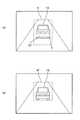
以上説明した制御処理によれば、自車の前方に先行車10が1台いる場合(図3(a)のような画像がカメラ1により撮影されている場合)、ステップS1の測定動作によって、例えば図3(a),(b)に示すような複数の測距ポイントCi(i=0、…、N−1)が得られる。
そして、ステップS2〜S6の処理によって、図6(a)に示すように、一つの測距ポイントCiに対して一つの矩形領域Kiが求められ、ステップS2〜S6が繰り返されることによって、図6(b)に示すように(煩雑を避けるため、図6(b)では測距ポイントC1〜C3と矩形領域K1〜K3のみに符号を付している)、全ての測距ポイントCiに対してそれぞれ矩形領域Kiが求められる。その後ステップS8〜S10の処理によって、図6(c)に示すように、各矩形領域Kiが統合された矩形領域Kが最終的に画像処理エリアとして決定される。
なお、例えば通常の自動車よりも横幅の狭い自転車などに対しては、自動車に比較して統合される矩形エリアの数(即ち、測距ポイントの数)が少なくなり、その分だけ最終的な画像処理エリアが狭くなり、一方トラックなどの大型な物体に対しては、その分だけ最終的な画像処理エリアが広くなり、結局、物体の横幅に応じた適度な横幅をもつ画像処理エリアが決定される。According to the control process described above, when there is one preceding
Then, by the processing of steps S2 to S6, as shown in FIG. 6A, one rectangular area Ki is obtained for one distance measuring point Ci, and steps S2 to S6 are repeated, whereby FIG. As shown in (b) (in order to avoid complication, only the ranging points C1 to C3 and the rectangular areas K1 to K3 are labeled in FIG. 6B), all the ranging points Ci are used. A rectangular area Ki is obtained for each. Thereafter, as shown in FIG. 6C, a rectangular area K obtained by integrating the rectangular areas Ki is finally determined as an image processing area by the processes in steps S8 to S10.
For example, for a bicycle having a narrower width than that of a normal automobile, the number of rectangular areas to be integrated (that is, the number of distance measuring points) is smaller than that of an automobile, and the final image is accordingly increased. On the other hand, for large objects such as trucks, the final image processing area will be widened accordingly, and eventually an image processing area with an appropriate width corresponding to the width of the object will be determined. The
本例の車載用画像処理装置によれば、物体が存在するとして検出された測定位置を中心として、レーダのビーム断面に応じた拡がりをもつ領域が、画像処理エリアとして決定される。また、物体がレーダの走査方向にある程度の大きさを持つ場合には、上記測定位置は走査方向に複数存在し、それに対応して画像処理エリアも複数決定される。
このため、ビーム断面の拡がりを適度に設定すれば、決定された画像処理エリア全体(複数ある場合には、これらの集合)は、少なくとも走査方向においては、物体の大きさにかかわらず物体とその周辺を適度に含む適切な領域となる。例えば、人や自転車のように比較的小さな物体の場合には、上記測定位置の数が少なくなり、その分だけ画像処理エリアが走査方向に狭くなる。一方、例えば通常の自動車や大型トラックのように比較的大きな物体の場合には、上記測定位置の数がその大きさに応じて多くなり、その分だけ画像処理エリアが走査方向に広くなる。According to the vehicle-mounted image processing apparatus of this example, an area having an extent corresponding to the beam cross section of the radar with the measurement position detected as the presence of an object as the center is determined as the image processing area. When the object has a certain size in the scanning direction of the radar, there are a plurality of measurement positions in the scanning direction, and a plurality of image processing areas are determined correspondingly.
For this reason, if the spread of the beam cross section is set appropriately, the entire determined image processing area (a set of these if there are a plurality of images) is the object and its object regardless of the size of the object, at least in the scanning direction. It becomes an appropriate area including the periphery moderately. For example, in the case of a relatively small object such as a person or a bicycle, the number of measurement positions is reduced, and the image processing area is narrowed in the scanning direction accordingly. On the other hand, in the case of a relatively large object such as a normal automobile or a large truck, the number of measurement positions increases according to the size, and the image processing area becomes wider in the scanning direction.
また本例によれば、前述したようにビーム断面の拡がりに応じて画像処理エリアを決定するため、物体の大きさ自体をレーダによって正確に判定しなくてもよい。このため、特許文献2の装置のようにレーダの走査方向の分解能を高める必要がなく、高い応答性や省エネ性が実現できる。
また本例では、レーダによって検出された物体の測定位置が複数あり、これら測定位置がレーダの分解能以下又は分解能近くに接近している場合には、これらの測定位置を同一物体のものとしてグループ化し、これら測定位置に基づく画像処理エリアを一つの画像処理エリアとして統合する。このため、同一物体の画像処理エリアが統合され、物体を個々に識別するための画像処理が容易になる利点がある。In addition, according to this example, since the image processing area is determined according to the spread of the beam cross section as described above, it is not necessary to accurately determine the size of the object itself by the radar. For this reason, it is not necessary to increase the resolution in the scanning direction of the radar unlike the apparatus of
Also, in this example, when there are multiple measurement positions of objects detected by the radar and these measurement positions are close to or below the resolution of the radar, these measurement positions are grouped as those of the same object. The image processing areas based on these measurement positions are integrated as one image processing area. For this reason, there is an advantage that the image processing areas of the same object are integrated, and the image processing for individually identifying the object becomes easy.
また本例では、レーダ2のビームの拡がり角が、何れの方向についても、撮像手段(カメラ1)の画角に比べて小さい。このため、画像処理エリアを、何れの方向についても、撮像手段により得られる画像よりも小さく制限することが可能となり、画像処理の負担を減らす効果が顕著になる。なお上記形態例において、走査を行わない上下方向については、ビームの拡がり角をカメラの画角と同じか広く設定してもよい。この場合でも走査方向(横方向)については、画像処理エリアを制限することができる。
また本例では、レーダから出力される電磁波の円形又は楕円系のビーム断面形状に、内接又は外接する矩形領域として、画像処理エリアを決定する。このため、画像処理エリアが矩形となり、画像処理エリアの設定が容易になる。特に本例では、矩形領域の対角に位置する二つの角位置によって、画像処理エリアを特定するため、画像処理エリアを特定するための処理データ量が少なくてすむという利点がある。In this example, the beam divergence angle of the
In this example, the image processing area is determined as a rectangular area that is inscribed or circumscribed to the circular or elliptical beam cross-sectional shape of the electromagnetic wave output from the radar. For this reason, the image processing area becomes rectangular, and the setting of the image processing area becomes easy. In particular, in this example, since the image processing area is specified by two corner positions located at the opposite corners of the rectangular area, there is an advantage that the amount of processing data for specifying the image processing area can be reduced.
(第2形態例)
次に、レーダの走査を行わない上下方向における下限側で、画像処理エリアをさらに制限する態様(第2形態例)を説明する。なお、以下では、第1形態例と同様の構成については説明を省略する。
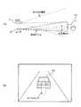
この例では、前述した図7の一連の処理におけるステップS10とステップS11の間において、画像処理装置3が次のような処理を実行する。
まず、自車が走行する路面に平行な平面11(例えば、自車が走行するタイヤ接地平面そのもの、或いはこの平面を上下に所定量平行移動させた平面)を仮定する。この平面11は、例えばカメラ1と車体(タイヤ接地平面)とが平行な場合には、カメラ座標系(Xc、Yc、Zc)においては、高さ方向の座標Xcのデータ(例えば、タイヤ接地平面からカメラ1の光軸までの高さのデータ)によって特定できる。またこの平面11は、路面が平坦である場合には、図8(a)に示す如く、先行車10等が走行する路面にも当然に平行である。次に、レーダによって検出された物体の測定位置(例えば、前述のステップS5で得られた測距ポイントCiの座標データ)を、図8(b)に示すように平面11に投影し、この投影された投影ポイントCi´の座標を求める。次いで、図9(a)に示すように、これら投影ポイントCi´を2点以上結んでなる線Lを求める。そして、図9(b)や図10(a)に示すように、この線Lを画像座標に変換し、図10(b)に示すようにこの変換後の線Lによって前記画像処理エリアKの下限を限定して、最終的な画像処理エリアK´を決定する。(Second embodiment)
Next, a mode (second mode example) in which the image processing area is further limited on the lower limit side in the vertical direction in which radar scanning is not performed will be described. In the following, description of the same configuration as that of the first embodiment will be omitted.
In this example, the image processing apparatus 3 executes the following process between step S10 and step S11 in the series of processes shown in FIG.
First, a
本例の場合、上下方向に走査を行わない一次元スキャン方式のレーダを使用して、上下方向のビームの拡がりを検出漏れがないように十分広く設定した場合でも、画像処理エリアの下限を必要最小限に制限することができ、画像処理エリアの上下方向の無用な拡がりを制限して、それによる画像処理の負担増を回避できる。
なおこの場合、図11(a)に示すように、画像座標への変換後の線L(下限の線)に接する位置から画像処理のラスタスキャンを開始する態様とすることが望ましい。このようにすると、物体の下部位置から画像処理を開始することになり、物体をより早く画像処理によって識別できる。なお、図11(a)において、符号12はラスタスキャンの特徴抽出ウインドウ(複数の画素よりなる領域、例えば図11(b)に示すような3×3ピクセルの領域)を示し、図11(b)は、このウインドウの画像データ例(例えば画像の明暗の値)を示す図である。ラスタスキャンは、このようなウインドウを例えば図11(a)に矢印で示すように、ジグザグに走査しつつ、画像データの積和演算による物体画像のエッジ抽出などを行うためのものである。In the case of this example, the lower limit of the image processing area is required even if the beam spread in the vertical direction is set wide enough so that there is no omission of detection using a one-dimensional scanning radar that does not scan in the vertical direction. It is possible to limit the image processing area to the minimum, and to limit unnecessary expansion of the image processing area in the vertical direction, thereby avoiding an increase in the burden of image processing.
In this case, as shown in FIG. 11A, it is desirable that the raster scan of the image processing is started from a position in contact with the line L (lower limit line) after conversion into image coordinates. In this way, image processing starts from the lower position of the object, and the object can be identified earlier by image processing. In FIG. 11A,
(第3形態例)
次に、レーダ2が測定した物体までの距離が増加するのに応じて、図12に示すように、画像処理エリア(ビーム断面の拡がり)の大きさを小さくする態様(第3形態例)を説明する。
この例では、前述した図7の一連の処理におけるステップS3において、画像処理装置3が、例えば次の処理(イ)〜(ハ)のうちの何れかを実行する。
(イ)数4に示す関係式に基づき、レーダの測定結果としてステップS2で得られた距離ZLのデータに応じてビーム径を変更する。数4において、aは変更前のビーム径、a´は変更後のビーム径、dは基準となる距離データ、d´は測定結果としての距離データである(図12(a),(b)参照)。また、Kは調整のための定数である。(Third embodiment)
Next, as shown in FIG. 12, as the distance to the object measured by the
In this example, the image processing apparatus 3 executes, for example, any one of the following processes (A) to (C) in step S3 in the series of processes shown in FIG.
(A) Based on the relational expression shown in Equation 4, the beam diameter is changed according to the data of the distance ZL obtained in step S2 as a radar measurement result. In Equation 4, a is the beam diameter before the change, a ′ is the beam diameter after the change, d is the reference distance data, and d ′ is the distance data as a measurement result (FIGS. 12A and 12B). reference). K is a constant for adjustment.
(ロ)数5に示す関係式に基づき、前記距離ZLのデータに応じてビーム断面積が変化するように、ビーム径を変更する。数5において、Sは変更前のビーム断面積、S´は変更後のビーム断面積、dは基準となる距離データ、d´は測定結果としての距離データである(図12(a),(b)参照)。また、Kは調整のための定数である。(B) Based on the relational expression shown in Equation 5, the beam diameter is changed so that the beam cross-sectional area changes according to the data of the distance ZL. In Equation 5, S is the beam cross-sectional area before the change, S ′ is the beam cross-sectional area after the change, d is the reference distance data, and d ′ is the distance data as the measurement result (FIGS. 12A and 12B). b)). K is a constant for adjustment.
(ハ)数6に示す関係式に基づき、前記距離ZLのデータに応じてビーム拡がり角を変化させ、その結果に応じてビーム径を変更する。数6において、θは変更前のビーム拡がり角、θ´は変更後のビーム拡がり角、dは基準となる距離データ、d´は測定結果としての距離データである(図12(c),(d)参照)。また、Kは調整のための定数である。(C) Based on the relational expression shown in Equation 6, the beam divergence angle is changed according to the data of the distance ZL, and the beam diameter is changed according to the result. In Equation 6, θ is the beam divergence angle before the change, θ ′ is the beam divergence angle after the change, d is the reference distance data, and d ′ is the distance data as the measurement result (FIGS. 12C and 12C). d)). K is a constant for adjustment.
なお本例では、便宜上ビーム断面が円形である場合について説明したが、第1形態例のように楕円形である場合にも、本例と同様の態様とすることができる。長軸側と短軸側の2種類のビーム径を、同様に変更すればよい。
以上説明した第3形態例の態様であると、物体までの距離が離れても、画像処理エリアを必要最小限の最適な大きさとすることができる。遠方からの反射光はビーム中心の強度が高いところからしか返ってこなくなり、物体はビームのより中心側に存在するようになるからである。In this example, the case where the beam cross section is circular has been described for the sake of convenience. However, in the case where the beam cross section is elliptical as in the first embodiment, the same mode as in this example can be adopted. The two types of beam diameters on the long axis side and the short axis side may be similarly changed.
With the aspect of the third embodiment described above, the image processing area can be set to the optimum minimum size even if the distance to the object is long. This is because the reflected light from far away returns only from the place where the intensity at the center of the beam is high, and the object comes to be closer to the center of the beam.
(第4形態例)
次に、レーダ2とカメラ1の中心軸のなす角度に応じて、画像処理エリアの位置を補正する態様(第4形態例)を説明する。
この例では、前述した図7の一連の処理における例えばステップS2とステップS3の間において、画像処理装置3が次のような補正処理を実行する。
すなわち、レーダ2とカメラ1の中心軸の上下方向のなす角度を、ずれ角dθ(図14(a)参照)とした場合、各測距ポイントCiのXL方向(上下方向)の座標データを、「H」から「H+ZL×tan(dθ)」に変更する。(Fourth embodiment)
Next, a mode (fourth mode) for correcting the position of the image processing area according to the angle formed by the center axis of the
In this example, the image processing apparatus 3 executes the following correction process, for example, between step S2 and step S3 in the series of processes shown in FIG.
That is, when the angle between the vertical axis of the
図13(a)に示すように、レーダ2とカメラ1の中心軸が平行な状態で座標変換式を設定した場合、レーダ2とカメラ1の中心軸が平行状態に維持されている限り、ビームエリアの位置(即ち、画像処理エリアの位置)は、図13(b)に示す如く適正状態に維持される。ところが、なんらかの原因で図14(a)に示す如く上記各軸が平行でなくなると、そのままでは図14(b)に示す如く画像処理エリアが適正位置からずれてしまう。しかし本形態例であると、そのずれ角dθが分かっている場合(例えば、先行車が接近するとそれに応じて光軸を上向きに変更する機能と、そのための角度センサとを持つレーダの場合)には、画像処理エリアを、上記補正処理によって適正状態(図13(b)に示す位置)に修正することができるという効果がある。 As shown in FIG. 13A, when the coordinate conversion equation is set in a state where the center axis of the
なお、本発明は上述した形態例に限られず、各種の変形や応用があり得る。
例えば、二次元スキャン方式のレーダをもつシステムに本発明を適用してもよい。この場合、前述したように画像処理エリアが適切な大きさになる効果は、各走査方向について得られる。
また、電磁波のビームの断面形状は、円形であってもよい。例えば二次元スキャン方式のレーダの場合には、上下方向での検出漏れを防止するために上下方向にビームを長くする必要性が低下するので、円形にし易い。The present invention is not limited to the above-described embodiments, and various modifications and applications are possible.
For example, the present invention may be applied to a system having a two-dimensional scanning radar. In this case, as described above, the effect that the image processing area becomes an appropriate size can be obtained in each scanning direction.
The cross-sectional shape of the electromagnetic wave beam may be circular. For example, in the case of a two-dimensional scan type radar, the necessity of elongating the beam in the vertical direction in order to prevent detection omission in the vertical direction is reduced, so that it is easy to make it circular.
1 カメラ(撮像手段)
2 レーザレーダ
3 画像処理装置(画像処理手段、画像処理エリア決定手段)1 Camera (imaging means)
2 Laser radar 3 Image processing device (image processing means, image processing area determination means)
Claims (11)
Translated fromJapanese前記レーダによって検出された物体の測定位置に応じて、前記画像処理エリアの中心位置を決定し、前記レーダから出力される電磁波のビームプロファイルに応じて、前記画像処理エリアの大きさを決定する画像処理エリア決定手段を設けたことを特徴とする車載用画像処理装置。A radar that measures the distance and direction to an object existing outside the vehicle based on the reflected wave of the electromagnetic wave output while scanning outside the vehicle, an imaging unit for acquiring an image outside the vehicle, and an image obtained by the imaging unit In-vehicle image processing apparatus comprising: image processing means for performing image processing on a predetermined image processing area of
An image for determining the center position of the image processing area according to the measurement position of the object detected by the radar, and for determining the size of the image processing area according to the beam profile of the electromagnetic wave output from the radar An in-vehicle image processing apparatus comprising a processing area determining unit.
前記レーダによって検出された物体の測定位置が複数あり、これら測定位置が前記レーダの分解能以下又は分解能近くに接近している場合には、これらの測定位置を同一物体のものとしてグループ化し、これら測定位置に基づく前記画像処理エリアを一つの画像処理エリアとして統合することを特徴とする請求項1に記載の車載用画像処理装置。The image processing area determining means includes
When there are a plurality of measurement positions of the objects detected by the radar and these measurement positions are close to or close to the resolution of the radar, these measurement positions are grouped as those of the same object, and these measurements are performed. The in-vehicle image processing apparatus according to claim 1, wherein the image processing areas based on the position are integrated as one image processing area.
自車が走行する路面に平行な平面を仮定し、前記レーダによって検出された物体の測定位置を前記平面に投影し、この投影された位置を2点以上結んでなる線を画像座標に変換し、この変換後の線によって前記画像処理エリアの下限を限定することを特徴とする請求項1〜4の何れかに記載の車載用画像処理装置。The image processing area determining means includes
Assuming a plane parallel to the road surface on which the vehicle is traveling, the measurement position of the object detected by the radar is projected onto the plane, and a line connecting two or more of the projected positions is converted into image coordinates. The in-vehicle image processing apparatus according to claim 1, wherein a lower limit of the image processing area is limited by the line after the conversion.
前記変換後の線に接する位置から画像処理のラスタスキャンを開始することを特徴とする請求項5に記載の車載用画像処理装置。The image processing means includes
6. The in-vehicle image processing apparatus according to claim 5, wherein a raster scan of image processing is started from a position in contact with the converted line.
前記レーダから出力される電磁波のビーム強度が最大値の半分となる位置に応じて、前記画像処理エリアの大きさを決定することを特徴とする請求項1〜6の何れかに記載の車載用画像処理装置。The image processing area determining means includes
The in-vehicle use according to claim 1, wherein the size of the image processing area is determined according to a position at which a beam intensity of an electromagnetic wave output from the radar is half of a maximum value. Image processing device.
前記レーダによって検出された物体までの距離が増加するのに応じて、前記画像処理エリアの大きさを小さくすることを特徴とする請求項1〜7の何れかに記載の車載用画像処理装置。The image processing area determining means includes
The in-vehicle image processing device according to claim 1, wherein the size of the image processing area is reduced as the distance to the object detected by the radar increases.
前記レーダから出力される電磁波の円形又は楕円系のビーム断面形状に、内接又は外接する矩形領域として、前記画像処理エリアを決定することを特徴とする請求項1〜9の何れかに記載の車載用画像処理装置。The image processing area determining means includes
10. The image processing area according to claim 1, wherein the image processing area is determined as a rectangular area that is inscribed or circumscribed in a circular or elliptical beam cross-sectional shape of the electromagnetic wave output from the radar. In-vehicle image processing device.
前記矩形領域の対角に位置する二つの角位置によって、前記画像処理エリアを特定することを特徴とする請求項10に記載の車載用画像処理装置。The image processing area determining means includes
The in-vehicle image processing apparatus according to claim 10, wherein the image processing area is specified by two corner positions located diagonally to the rectangular area.
Priority Applications (6)
| Application Number | Priority Date | Filing Date | Title |
|---|---|---|---|
| JP2004342950AJP2006151125A (en) | 2004-11-26 | 2004-11-26 | On-vehicle image processing device |
| DE602005004365TDE602005004365T2 (en) | 2004-11-26 | 2005-11-10 | Image processing system for automotive applications |
| EP05024581AEP1666919B1 (en) | 2004-11-26 | 2005-11-10 | Image processing system for automotive application |
| EP07112304AEP1847849A3 (en) | 2004-11-26 | 2005-11-10 | Image processing system for automotive application |
| US11/280,745US7176830B2 (en) | 2004-11-26 | 2005-11-15 | Image processing system for mounting to a vehicle |
| CNB2005101243482ACN100451676C (en) | 2004-11-26 | 2005-11-25 | Image processing system for mounting to a vehicle |
Applications Claiming Priority (1)
| Application Number | Priority Date | Filing Date | Title |
|---|---|---|---|
| JP2004342950AJP2006151125A (en) | 2004-11-26 | 2004-11-26 | On-vehicle image processing device |
Publications (2)
| Publication Number | Publication Date |
|---|---|
| JP2006151125Atrue JP2006151125A (en) | 2006-06-15 |
| JP2006151125A5 JP2006151125A5 (en) | 2007-02-15 |
Family
ID=36127311
Family Applications (1)
| Application Number | Title | Priority Date | Filing Date |
|---|---|---|---|
| JP2004342950APendingJP2006151125A (en) | 2004-11-26 | 2004-11-26 | On-vehicle image processing device |
Country Status (5)
| Country | Link |
|---|---|
| US (1) | US7176830B2 (en) |
| EP (2) | EP1666919B1 (en) |
| JP (1) | JP2006151125A (en) |
| CN (1) | CN100451676C (en) |
| DE (1) | DE602005004365T2 (en) |
Cited By (22)
| Publication number | Priority date | Publication date | Assignee | Title |
|---|---|---|---|---|
| EP1944721A2 (en) | 2007-01-10 | 2008-07-16 | Omron Corporation | Image processing apparatus, method and program product thereof |
| EP1950689A2 (en) | 2007-01-10 | 2008-07-30 | Omron Corporation | Detection device, method and program thereof |
| JP2008177768A (en)* | 2007-01-17 | 2008-07-31 | Mitsubishi Electric Corp | Image transmission apparatus and image transmission method |
| EP1959675A2 (en) | 2007-02-16 | 2008-08-20 | Omron Corporation | Detection device, method and program thereof |
| WO2008139529A1 (en) | 2007-04-27 | 2008-11-20 | Honda Motor Co., Ltd. | Vehicle periphery monitoring system, vehicle periphery monitoring program and vehicle periphery monitoring method |
| JP2009139228A (en)* | 2007-12-06 | 2009-06-25 | Toyota Motor Corp | Object detection device |
| JP2009217680A (en)* | 2008-03-12 | 2009-09-24 | Omron Corp | Transverse object detection device and transverse object detecting method, and program |
| WO2009157548A1 (en) | 2008-06-27 | 2009-12-30 | トヨタ自動車株式会社 | Object detector |
| WO2010026959A1 (en)* | 2008-09-05 | 2010-03-11 | トヨタ自動車株式会社 | Object detecting device |
| JP2010164443A (en)* | 2009-01-16 | 2010-07-29 | Nec Corp | Location information analyzer, location information analysis method, location information analysis system and program |
| JP5145599B2 (en)* | 2007-04-27 | 2013-02-20 | 本田技研工業株式会社 | Vehicle periphery monitoring device, vehicle periphery monitoring program, and vehicle periphery monitoring method |
| WO2013108664A1 (en)* | 2012-01-16 | 2013-07-25 | トヨタ自動車株式会社 | Object detection device |
| JP2014142202A (en)* | 2013-01-22 | 2014-08-07 | Denso Corp | Vehicle-mounted target detection device |
| WO2016027652A1 (en)* | 2014-08-18 | 2016-02-25 | 株式会社デンソー | Object recognition device |
| JP2016158079A (en)* | 2015-02-24 | 2016-09-01 | 株式会社東芝 | Mobile optical communication system, and optical transmitter thereof, and imaging control method |
| JP2017174197A (en)* | 2016-03-24 | 2017-09-28 | 日産自動車株式会社 | Three-dimensional object detection method and three-dimensional object detection device |
| JP2018037737A (en)* | 2016-08-29 | 2018-03-08 | 株式会社Soken | Periphery monitoring device and periphery monitoring method |
| JP2018159574A (en)* | 2017-03-22 | 2018-10-11 | 本田技研工業株式会社 | Method for specifying noise data of laser type distance measuring device |
| WO2020116204A1 (en)* | 2018-12-07 | 2020-06-11 | ソニーセミコンダクタソリューションズ株式会社 | Information processing device, information processing method, program, moving body control device, and moving body |
| JPWO2022019117A1 (en)* | 2020-07-21 | 2022-01-27 | ||
| WO2022210062A1 (en)* | 2021-03-29 | 2022-10-06 | 京セラ株式会社 | Information processing device, vehicle, roadside unit, and information processing method |
| WO2023190058A1 (en)* | 2022-03-30 | 2023-10-05 | パナソニックIpマネジメント株式会社 | Image processing method and image processing device |
Families Citing this family (70)
| Publication number | Priority date | Publication date | Assignee | Title |
|---|---|---|---|---|
| US7796081B2 (en)* | 1997-10-22 | 2010-09-14 | Intelligent Technologies International, Inc. | Combined imaging and distance monitoring for vehicular applications |
| US9428186B2 (en) | 2002-04-09 | 2016-08-30 | Intelligent Technologies International, Inc. | Exterior monitoring for vehicles |
| JP4595833B2 (en)* | 2006-02-24 | 2010-12-08 | トヨタ自動車株式会社 | Object detection device |
| US8050863B2 (en) | 2006-03-16 | 2011-11-01 | Gray & Company, Inc. | Navigation and control system for autonomous vehicles |
| US8330647B2 (en)* | 2006-06-08 | 2012-12-11 | Vista Research, Inc. | Sensor suite and signal processing for border surveillance |
| EP2122599B1 (en)* | 2007-01-25 | 2019-11-13 | Magna Electronics Inc. | Radar sensing system for vehicle |
| JP4861855B2 (en)* | 2007-02-15 | 2012-01-25 | 株式会社バンダイナムコゲームス | Pointed position calculation system, pointer and game system |
| JP5132164B2 (en)* | 2007-02-22 | 2013-01-30 | 富士通株式会社 | Background image creation device |
| JP5160114B2 (en)* | 2007-03-26 | 2013-03-13 | 本田技研工業株式会社 | Vehicle passage judgment device |
| US8049658B1 (en)* | 2007-05-25 | 2011-11-01 | Lockheed Martin Corporation | Determination of the three-dimensional location of a target viewed by a camera |
| DE102007046287B4 (en)* | 2007-09-27 | 2009-07-30 | Siemens Ag | Method for calibrating a sensor arrangement |
| US8106755B1 (en)* | 2008-02-14 | 2012-01-31 | Epsilon Lambda Electronics Corp. | Triple-function vehicle safety sensor system |
| DE102008039606A1 (en)* | 2008-08-25 | 2010-03-04 | GM Global Technology Operations, Inc., Detroit | Motor vehicle with a distance sensor and an image acquisition system |
| CN101769723B (en)* | 2008-12-30 | 2013-07-03 | 鸿富锦精密工业(深圳)有限公司 | Electronic device and object shape parameter measurement method thereof |
| JP5190712B2 (en)* | 2009-03-24 | 2013-04-24 | アイシン精機株式会社 | Obstacle detection device |
| KR101043450B1 (en)* | 2009-07-31 | 2011-06-21 | 삼성전기주식회사 | Position and distance measuring device and camera using position and distance measuring method |
| US8306672B2 (en)* | 2009-09-09 | 2012-11-06 | GM Global Technology Operations LLC | Vehicular terrain detection system and method |
| KR101030763B1 (en)* | 2010-10-01 | 2011-04-26 | 위재영 | Image Acquisition Units, Methods, and Associated Control Units |
| JP2013002927A (en)* | 2011-06-15 | 2013-01-07 | Honda Elesys Co Ltd | Obstacle detection apparatus and computer program |
| CN104488011B (en)* | 2012-07-27 | 2017-03-15 | 京瓷株式会社 | Image processing equipment, imaging device, movable body and area setting method |
| JP5812064B2 (en) | 2012-11-22 | 2015-11-11 | 株式会社デンソー | Target detection device |
| JP5754470B2 (en)* | 2012-12-20 | 2015-07-29 | 株式会社デンソー | Road surface shape estimation device |
| US9167214B2 (en) | 2013-01-18 | 2015-10-20 | Caterpillar Inc. | Image processing system using unified images |
| US9052393B2 (en) | 2013-01-18 | 2015-06-09 | Caterpillar Inc. | Object recognition system having radar and camera input |
| US20140205139A1 (en)* | 2013-01-18 | 2014-07-24 | Caterpillar Inc. | Object recognition system implementing image data transformation |
| US9557415B2 (en)* | 2014-01-20 | 2017-01-31 | Northrop Grumman Systems Corporation | Enhanced imaging system |
| JP6403393B2 (en)* | 2014-02-12 | 2018-10-10 | 住友重機械工業株式会社 | Image generation device |
| JP6190758B2 (en)* | 2014-05-21 | 2017-08-30 | 本田技研工業株式会社 | Object recognition device and vehicle |
| KR102273027B1 (en) | 2014-06-09 | 2021-07-05 | 삼성전자주식회사 | Method and apparatus for generating image data using a region of interest which is determined by position information |
| US10018709B2 (en)* | 2014-09-19 | 2018-07-10 | GM Global Technology Operations LLC | Radar target detection via multi-dimensional cluster of reflectors |
| US10890648B2 (en)* | 2014-10-24 | 2021-01-12 | Texas Instruments Incorporated | Method and apparatus for generating alignment matrix for camera-radar system |
| US10082563B2 (en)* | 2014-12-17 | 2018-09-25 | Northrop Grumman Systems Corporation | Synthesized profile |
| US9625582B2 (en)* | 2015-03-25 | 2017-04-18 | Google Inc. | Vehicle with multiple light detection and ranging devices (LIDARs) |
| US9891313B2 (en)* | 2015-05-08 | 2018-02-13 | Htc Corporation | Radar device and security monitoring system |
| US10102419B2 (en)* | 2015-10-30 | 2018-10-16 | Intel Corporation | Progressive radar assisted facial recognition |
| US20170242117A1 (en)* | 2016-02-19 | 2017-08-24 | Delphi Technologies, Inc. | Vision algorithm performance using low level sensor fusion |
| US10359779B2 (en) | 2016-03-22 | 2019-07-23 | Aurora Flight Sciences Corporation | Aircrew automation system and method |
| US10145951B2 (en) | 2016-03-30 | 2018-12-04 | Aptiv Technologies Limited | Object detection using radar and vision defined image detection zone |
| CN105806563A (en)* | 2016-05-17 | 2016-07-27 | 福建工程学院 | Intelligent auxiliary operation device and method for stone mine fork loading truck |
| CN106044663B (en)* | 2016-06-23 | 2018-12-18 | 福建工程学院 | A kind of view-based access control model technology can the forklift truck of check weighing stone digging and its method for measuring weight |
| CN106405555B (en)* | 2016-09-23 | 2019-01-01 | 百度在线网络技术(北京)有限公司 | Obstacle detection method and device for Vehicular radar system |
| KR101967305B1 (en)* | 2016-10-14 | 2019-05-15 | 주식회사 만도 | Pedestrian detecting method in a vehicle and system thereof |
| CN106647740A (en)* | 2016-11-15 | 2017-05-10 | 江苏智石科技有限公司 | Grating-based intelligent magazine transport vehicle |
| KR102313026B1 (en)* | 2017-04-11 | 2021-10-15 | 현대자동차주식회사 | Vehicle and method for collision avoidance assist when backing up the vehicle |
| US10816970B2 (en) | 2017-06-15 | 2020-10-27 | Aurora Flight Sciences Corporation | System and method for performing an emergency descent and landing |
| JP6988200B2 (en)* | 2017-06-29 | 2022-01-05 | 株式会社デンソー | Vehicle control device |
| CN109238293A (en)* | 2017-07-10 | 2019-01-18 | 李公健 | A kind of system and method for long-range management bicycle parking posture |
| US10453351B2 (en) | 2017-07-17 | 2019-10-22 | Aurora Flight Sciences Corporation | System and method for detecting obstacles in aerial systems |
| US10509415B2 (en) | 2017-07-27 | 2019-12-17 | Aurora Flight Sciences Corporation | Aircrew automation system and method with integrated imaging and force sensing modalities |
| US10962641B2 (en) | 2017-09-07 | 2021-03-30 | Magna Electronics Inc. | Vehicle radar sensing system with enhanced accuracy using interferometry techniques |
| US10877148B2 (en) | 2017-09-07 | 2020-12-29 | Magna Electronics Inc. | Vehicle radar sensing system with enhanced angle resolution using synthesized aperture |
| US10962638B2 (en) | 2017-09-07 | 2021-03-30 | Magna Electronics Inc. | Vehicle radar sensing system with surface modeling |
| US11150342B2 (en) | 2017-09-07 | 2021-10-19 | Magna Electronics Inc. | Vehicle radar sensing system with surface segmentation using interferometric statistical analysis |
| US20190120934A1 (en)* | 2017-10-19 | 2019-04-25 | GM Global Technology Operations LLC | Three-dimensional alignment of radar and camera sensors |
| US10841496B2 (en) | 2017-10-19 | 2020-11-17 | DeepMap Inc. | Lidar to camera calibration based on edge detection |
| US10297152B1 (en)* | 2017-10-27 | 2019-05-21 | Waymo Llc | Displaying sensor data and supplemental data as a mask for autonomous vehicles |
| CN112204343B (en)* | 2018-03-02 | 2024-05-17 | 辉达公司 | Visualization of high-definition map data |
| US10850397B2 (en) | 2018-04-19 | 2020-12-01 | Aurora Flight Sciences Corporation | System and method for providing in-cockpit actuation of aircraft controls |
| US10875662B2 (en) | 2018-04-19 | 2020-12-29 | Aurora Flight Sciences Corporation | Method of robot manipulation in a vibration environment |
| JP2021532382A (en)* | 2018-07-30 | 2021-11-25 | ポニー エーアイ インコーポレイテッド | Systems and methods for calibrating in-vehicle vehicle cameras |
| US11399137B2 (en) | 2018-08-10 | 2022-07-26 | Aurora Flight Sciences Corporation | Object-tracking system |
| FR3085656B1 (en)* | 2018-09-11 | 2023-04-28 | Renault Sas | ROAD DETECTION METHOD FOR A MOTOR VEHICLE PROVIDED WITH A LIDAR SENSOR |
| US11037453B2 (en) | 2018-10-12 | 2021-06-15 | Aurora Flight Sciences Corporation | Adaptive sense and avoid system |
| US11151810B2 (en) | 2018-10-12 | 2021-10-19 | Aurora Flight Sciences Corporation | Adaptable vehicle monitoring system |
| US11059489B2 (en)* | 2018-10-24 | 2021-07-13 | Valeo Radar Systems, Inc. | Methods and systems for detecting road surface conditions |
| JP7185547B2 (en)* | 2019-02-07 | 2022-12-07 | 株式会社デンソー | vehicle detector |
| JP7215448B2 (en)* | 2020-02-28 | 2023-01-31 | 株式会社デンソー | Detector attitude/position detector |
| EP4099298B1 (en)* | 2021-05-31 | 2024-05-15 | Deutsche Telekom AG | Method for detecting hazards and / or collision avoidance in a moving vehicle, system, computer program and computer readable medium |
| EP4099297B1 (en)* | 2021-05-31 | 2024-02-21 | Deutsche Telekom AG | Method for detecting hazards and / or collision avoidance in a moving vehicle, system, computer program and computer readable medium |
| CN113625243A (en)* | 2021-07-28 | 2021-11-09 | 山东浪潮科学研究院有限公司 | Method and device for improving image signal-to-noise ratio of laser radar in severe weather |
Citations (7)
| Publication number | Priority date | Publication date | Assignee | Title |
|---|---|---|---|---|
| JPH09264954A (en)* | 1996-03-29 | 1997-10-07 | Fujitsu Ten Ltd | Image processing system using radar |
| JP3123303B2 (en)* | 1992-07-21 | 2001-01-09 | 日産自動車株式会社 | Vehicle image processing device |
| JP2001099930A (en)* | 1999-09-29 | 2001-04-13 | Fujitsu Ten Ltd | Sensor for monitoring periphery |
| JP2001296357A (en)* | 2000-04-14 | 2001-10-26 | Fujitsu Ten Ltd | Object detecting apparatus |
| JP3264060B2 (en)* | 1993-11-04 | 2002-03-11 | 三菱自動車工業株式会社 | The preceding vehicle detection mechanism of the vehicle travel control device |
| JP2003084064A (en)* | 2001-09-12 | 2003-03-19 | Daihatsu Motor Co Ltd | Device and method for recognizing vehicle in front side |
| JP2005284410A (en)* | 2004-03-26 | 2005-10-13 | Omron Corp | Vehicle recognition device and method |
Family Cites Families (23)
| Publication number | Priority date | Publication date | Assignee | Title |
|---|---|---|---|---|
| US4063073A (en)* | 1974-11-29 | 1977-12-13 | Strayer Larry G | Computer system to prevent collision between moving objects such as aircraft moving from one sector to another |
| JPS534932A (en)* | 1976-05-29 | 1978-01-18 | Nissan Motor Co Ltd | Device for collision avoidance of moving body |
| JPH0812072B2 (en)* | 1990-06-13 | 1996-02-07 | 三菱電機株式会社 | Distance measuring device |
| US5347459A (en)* | 1993-03-17 | 1994-09-13 | National Research Council Of Canada | Real time collision detection |
| JP3212218B2 (en)* | 1994-05-26 | 2001-09-25 | 三菱電機株式会社 | Obstacle detection device for vehicles |
| JP3044524B2 (en)* | 1995-05-23 | 2000-05-22 | 本田技研工業株式会社 | Method for detecting objects in vehicles |
| US5835880A (en)* | 1995-07-19 | 1998-11-10 | Vi & T Group, Inc. | Apparatus and method for vehicle following with dynamic feature recognition |
| DE69611278T2 (en)* | 1995-11-10 | 2001-05-23 | Toyota Jidosha K.K., Toyota | Radar device for detecting the direction of the center of a target |
| JP3331882B2 (en)* | 1995-12-27 | 2002-10-07 | 株式会社デンソー | Central axis deflection amount calculating device, central axis deflection amount correcting device, and inter-vehicle control device of vehicle obstacle detection device |
| JPH09222477A (en)* | 1996-02-19 | 1997-08-26 | Toyota Motor Corp | Automotive radar equipment |
| US6025797A (en)* | 1997-07-22 | 2000-02-15 | Denso Corporation | Angular shift determining apparatus for determining angular shift of central axis of radar used in automotive obstacle detection system |
| US5959569A (en)* | 1997-10-09 | 1999-09-28 | Eaton Vorad Technologies, L.L.C. | Method and apparatus for in path target determination for an automotive vehicle using a gyroscopic device |
| JP3480486B2 (en)* | 1998-08-18 | 2003-12-22 | トヨタ自動車株式会社 | FM-CW radar device |
| JP2000298164A (en)* | 1999-04-15 | 2000-10-24 | Honda Motor Co Ltd | Multi-channel radar device |
| US6121916A (en)* | 1999-07-16 | 2000-09-19 | Eaton-Vorad Technologies, L.L.C. | Method and apparatus for recognizing stationary objects with a moving side-looking radar |
| KR100662064B1 (en)* | 2001-03-15 | 2006-12-27 | 후지쓰 텐 가부시키가이샤 | Signal Processing Method of Scanning Radar |
| JP3729127B2 (en)* | 2001-12-13 | 2005-12-21 | 株式会社村田製作所 | Radar |
| US6771208B2 (en)* | 2002-04-24 | 2004-08-03 | Medius, Inc. | Multi-sensor system |
| JP3862015B2 (en)* | 2002-10-25 | 2006-12-27 | オムロン株式会社 | Automotive radar equipment |
| JP2004233275A (en)* | 2003-01-31 | 2004-08-19 | Denso Corp | Vehicle-mounted radar apparatus |
| US6674394B1 (en)* | 2003-03-28 | 2004-01-06 | Visteon Global Technologies, Inc. | Method for determining object location from side-looking sensor data |
| US6834232B1 (en)* | 2003-07-30 | 2004-12-21 | Ford Global Technologies, Llc | Dual disimilar sensing object detection and targeting system |
| JP3941765B2 (en)* | 2003-09-11 | 2007-07-04 | トヨタ自動車株式会社 | Object detection device |
- 2004
- 2004-11-26JPJP2004342950Apatent/JP2006151125A/enactivePending
- 2005
- 2005-11-10EPEP05024581Apatent/EP1666919B1/ennot_activeNot-in-force
- 2005-11-10EPEP07112304Apatent/EP1847849A3/ennot_activeWithdrawn
- 2005-11-10DEDE602005004365Tpatent/DE602005004365T2/enactiveActive
- 2005-11-15USUS11/280,745patent/US7176830B2/ennot_activeExpired - Fee Related
- 2005-11-25CNCNB2005101243482Apatent/CN100451676C/ennot_activeExpired - Fee Related
Patent Citations (7)
| Publication number | Priority date | Publication date | Assignee | Title |
|---|---|---|---|---|
| JP3123303B2 (en)* | 1992-07-21 | 2001-01-09 | 日産自動車株式会社 | Vehicle image processing device |
| JP3264060B2 (en)* | 1993-11-04 | 2002-03-11 | 三菱自動車工業株式会社 | The preceding vehicle detection mechanism of the vehicle travel control device |
| JPH09264954A (en)* | 1996-03-29 | 1997-10-07 | Fujitsu Ten Ltd | Image processing system using radar |
| JP2001099930A (en)* | 1999-09-29 | 2001-04-13 | Fujitsu Ten Ltd | Sensor for monitoring periphery |
| JP2001296357A (en)* | 2000-04-14 | 2001-10-26 | Fujitsu Ten Ltd | Object detecting apparatus |
| JP2003084064A (en)* | 2001-09-12 | 2003-03-19 | Daihatsu Motor Co Ltd | Device and method for recognizing vehicle in front side |
| JP2005284410A (en)* | 2004-03-26 | 2005-10-13 | Omron Corp | Vehicle recognition device and method |
Cited By (41)
| Publication number | Priority date | Publication date | Assignee | Title |
|---|---|---|---|---|
| EP1944721A2 (en) | 2007-01-10 | 2008-07-16 | Omron Corporation | Image processing apparatus, method and program product thereof |
| JP2008171140A (en)* | 2007-01-10 | 2008-07-24 | Omron Corp | Image processing apparatus, method and program |
| EP1950689A2 (en) | 2007-01-10 | 2008-07-30 | Omron Corporation | Detection device, method and program thereof |
| JP2008177768A (en)* | 2007-01-17 | 2008-07-31 | Mitsubishi Electric Corp | Image transmission apparatus and image transmission method |
| EP1959675A2 (en) | 2007-02-16 | 2008-08-20 | Omron Corporation | Detection device, method and program thereof |
| US8126210B2 (en) | 2007-04-27 | 2012-02-28 | Honda Motor Co., Ltd. | Vehicle periphery monitoring device, vehicle periphery monitoring program, and vehicle periphery monitoring method |
| WO2008139529A1 (en) | 2007-04-27 | 2008-11-20 | Honda Motor Co., Ltd. | Vehicle periphery monitoring system, vehicle periphery monitoring program and vehicle periphery monitoring method |
| JP5145599B2 (en)* | 2007-04-27 | 2013-02-20 | 本田技研工業株式会社 | Vehicle periphery monitoring device, vehicle periphery monitoring program, and vehicle periphery monitoring method |
| US8411145B2 (en) | 2007-04-27 | 2013-04-02 | Honda Motor Co., Ltd. | Vehicle periphery monitoring device, vehicle periphery monitoring program and vehicle periphery monitoring method |
| JP2009139228A (en)* | 2007-12-06 | 2009-06-25 | Toyota Motor Corp | Object detection device |
| JP2009217680A (en)* | 2008-03-12 | 2009-09-24 | Omron Corp | Transverse object detection device and transverse object detecting method, and program |
| WO2009157548A1 (en) | 2008-06-27 | 2009-12-30 | トヨタ自動車株式会社 | Object detector |
| WO2010026959A1 (en)* | 2008-09-05 | 2010-03-11 | トヨタ自動車株式会社 | Object detecting device |
| JP2010061567A (en)* | 2008-09-05 | 2010-03-18 | Toyota Motor Corp | Object detecting apparatus |
| US8466827B2 (en) | 2008-09-05 | 2013-06-18 | Toyota Jidosha Kabushiki Kaisha | Object detecting device |
| JP2010164443A (en)* | 2009-01-16 | 2010-07-29 | Nec Corp | Location information analyzer, location information analysis method, location information analysis system and program |
| WO2013108664A1 (en)* | 2012-01-16 | 2013-07-25 | トヨタ自動車株式会社 | Object detection device |
| US9342897B2 (en) | 2013-01-22 | 2016-05-17 | Denso Corporation | In-vehicle target detecting device |
| JP2014142202A (en)* | 2013-01-22 | 2014-08-07 | Denso Corp | Vehicle-mounted target detection device |
| WO2016027652A1 (en)* | 2014-08-18 | 2016-02-25 | 株式会社デンソー | Object recognition device |
| JP2016042288A (en)* | 2014-08-18 | 2016-03-31 | 株式会社デンソー | Object recognition device |
| JP2016158079A (en)* | 2015-02-24 | 2016-09-01 | 株式会社東芝 | Mobile optical communication system, and optical transmitter thereof, and imaging control method |
| JP2017174197A (en)* | 2016-03-24 | 2017-09-28 | 日産自動車株式会社 | Three-dimensional object detection method and three-dimensional object detection device |
| US10885354B2 (en) | 2016-08-29 | 2021-01-05 | Denso Corporation | Perimeter monitoring device and perimeter monitoring method |
| CN109643495B (en)* | 2016-08-29 | 2022-05-17 | 株式会社电装 | Periphery monitoring device and periphery monitoring method |
| WO2018043028A1 (en)* | 2016-08-29 | 2018-03-08 | 株式会社デンソー | Surroundings monitoring device and surroundings monitoring method |
| CN109643495A (en)* | 2016-08-29 | 2019-04-16 | 株式会社电装 | Periphery monitoring apparatus and environment monitoring method |
| JP2018037737A (en)* | 2016-08-29 | 2018-03-08 | 株式会社Soken | Periphery monitoring device and periphery monitoring method |
| JP2018159574A (en)* | 2017-03-22 | 2018-10-11 | 本田技研工業株式会社 | Method for specifying noise data of laser type distance measuring device |
| JP7483627B2 (en) | 2018-12-07 | 2024-05-15 | ソニーセミコンダクタソリューションズ株式会社 | Information processing device, information processing method, program, mobile body control device, and mobile body |
| JPWO2020116204A1 (en)* | 2018-12-07 | 2021-10-21 | ソニーセミコンダクタソリューションズ株式会社 | Information processing device, information processing method, program, mobile control device, and mobile |
| US11987271B2 (en) | 2018-12-07 | 2024-05-21 | Sony Semiconductor Solutions Corporation | Information processing apparatus, information processing method, mobile-object control apparatus, and mobile object |
| WO2020116204A1 (en)* | 2018-12-07 | 2020-06-11 | ソニーセミコンダクタソリューションズ株式会社 | Information processing device, information processing method, program, moving body control device, and moving body |
| WO2022019117A1 (en)* | 2020-07-21 | 2022-01-27 | ソニーセミコンダクタソリューションズ株式会社 | Information processing device, information processing method, and program |
| JPWO2022019117A1 (en)* | 2020-07-21 | 2022-01-27 | ||
| JP7676407B2 (en) | 2020-07-21 | 2025-05-14 | ソニーセミコンダクタソリューションズ株式会社 | Information processing device, information processing method, and program |
| JP2022152835A (en)* | 2021-03-29 | 2022-10-12 | 京セラ株式会社 | Information processor, vehicle, roadside machine, and information processing method |
| WO2022210062A1 (en)* | 2021-03-29 | 2022-10-06 | 京セラ株式会社 | Information processing device, vehicle, roadside unit, and information processing method |
| JP7589086B2 (en) | 2021-03-29 | 2024-11-25 | 京セラ株式会社 | Information processing device, vehicle, roadside unit, and information processing method |
| WO2023190058A1 (en)* | 2022-03-30 | 2023-10-05 | パナソニックIpマネジメント株式会社 | Image processing method and image processing device |
| JPWO2023190058A1 (en)* | 2022-03-30 | 2023-10-05 |
Also Published As
| Publication number | Publication date |
|---|---|
| EP1666919A3 (en) | 2006-10-18 |
| CN100451676C (en) | 2009-01-14 |
| EP1847849A2 (en) | 2007-10-24 |
| DE602005004365T2 (en) | 2009-01-02 |
| EP1666919A2 (en) | 2006-06-07 |
| EP1666919B1 (en) | 2008-01-16 |
| US7176830B2 (en) | 2007-02-13 |
| DE602005004365D1 (en) | 2008-03-06 |
| EP1847849A3 (en) | 2010-08-11 |
| CN1779483A (en) | 2006-05-31 |
| US20060125679A1 (en) | 2006-06-15 |
Similar Documents
| Publication | Publication Date | Title |
|---|---|---|
| JP2006151125A (en) | On-vehicle image processing device | |
| US11719788B2 (en) | Signal processing apparatus, signal processing method, and program | |
| US10935643B2 (en) | Sensor calibration method and sensor calibration apparatus | |
| US10262242B2 (en) | Image scanning system and image scanning method | |
| JP6540009B2 (en) | Image processing apparatus, image processing method, program, image processing system | |
| US7973911B2 (en) | Object measuring device and method for use in the device | |
| CN102016921B (en) | image processing device | |
| EP1942313A2 (en) | Apparatus and method of measuring distance using structured light | |
| EP2921992A2 (en) | Image processing device, drive support system, image processing method, and program | |
| US11954871B2 (en) | Apparatus and method for acquiring coordinate conversion information | |
| JP7095640B2 (en) | Object detector | |
| JPH09142236A (en) | Vehicle periphery monitoring method, periphery monitoring device, periphery monitoring device failure determination method, and periphery monitoring device failure determination device | |
| US12222458B2 (en) | Apparatus for determining orientation and position of sensor | |
| US12422557B2 (en) | Object recognition abnormality detection apparatus, object recognition abnormality detection program product, and object recognition abnormality detection method | |
| JP2001052171A (en) | Ambient environment recognition device | |
| CN108061905A (en) | A kind of pavement behavior detection method and device | |
| CN107886036B (en) | Vehicle control method and device and vehicle | |
| CN112485807A (en) | Object recognition device | |
| JPH08329397A (en) | Vehicle recognition device and vehicle approach notification device using the same | |
| CN118274785B (en) | Pavement elevation detection method, medium and system | |
| WO2024204271A1 (en) | Control device, and control method | |
| JP7064389B2 (en) | Vehicle measuring device and vehicle measuring program |
Legal Events
| Date | Code | Title | Description |
|---|---|---|---|
| A521 | Request for written amendment filed | Free format text:JAPANESE INTERMEDIATE CODE: A523 Effective date:20061227 | |
| A621 | Written request for application examination | Free format text:JAPANESE INTERMEDIATE CODE: A621 Effective date:20061227 | |
| A131 | Notification of reasons for refusal | Free format text:JAPANESE INTERMEDIATE CODE: A131 Effective date:20090310 | |
| A02 | Decision of refusal | Free format text:JAPANESE INTERMEDIATE CODE: A02 Effective date:20090907 |