JP2006146827A - Life watching method and life watching system - Google Patents
Life watching method and life watching systemDownload PDFInfo
- Publication number
- JP2006146827A JP2006146827AJP2004339660AJP2004339660AJP2006146827AJP 2006146827 AJP2006146827 AJP 2006146827AJP 2004339660 AJP2004339660 AJP 2004339660AJP 2004339660 AJP2004339660 AJP 2004339660AJP 2006146827 AJP2006146827 AJP 2006146827A
- Authority
- JP
- Japan
- Prior art keywords
- information
- consumer
- event
- browsing
- home
- Prior art date
- Legal status (The legal status is an assumption and is not a legal conclusion. Google has not performed a legal analysis and makes no representation as to the accuracy of the status listed.)
- Granted
Links
Images


Landscapes
- Management, Administration, Business Operations System, And Electronic Commerce (AREA)
- Medical Treatment And Welfare Office Work (AREA)
- Accommodation For Nursing Or Treatment Tables (AREA)
Abstract
Translated fromJapaneseDescription
Translated fromJapanese本発明は、高齢者などが生活する居宅における生活者の生活状況の情報を収集し、その収集した情報を別居家族などに提供する生活見守り方法および生活見守りシステムに関する。 The present invention relates to a life monitoring method and a life monitoring system for collecting information on a living situation of a consumer in a home where an elderly person or the like lives and providing the collected information to a separate family member.
現在、人口の高齢化が進行しており、高齢者が一人または二人で生活する家庭が増加してきている。このような高齢者に成人した子供がいても、その子供は別居していることが多い。高齢者は、病気もし易く、ちょっとしたことでけがなどをすることも多いので、その子供の多くは、別居している親の生活状況をきめ細かく把握し、高齢な親の病気や事故などに備えたいと思っている。 Currently, the aging of the population is progressing, and the number of households where one or two elderly people live is increasing. Even if such an elderly child has an adult child, the child is often separated. Elderly people are easy to get sick and often get hurt by a small amount of things, so many of their children want to be aware of the living conditions of parents who are separated and prepare for illnesses and accidents of older parents. I think.
一方、ネットワーク技術とディジタル技術の発展によって、多くの家庭内にインターネットに接続されたパソコンが普及し、さらには家庭内ネットワークが張られ、いまや、テレビや冷蔵庫などもその家庭内ネットワークを介してパソコンに接続されるようになってきた。また、簡単に取り扱える血圧計や体重計などの健康機器が一般家庭にかなり普及しており、これらの健康機器もパソコンに接続できるようになってきている。 On the other hand, the development of network technology and digital technology has led to the spread of personal computers connected to the Internet in many homes, and the establishment of home networks. Now, televisions and refrigerators are also connected to personal computers via the home network. It has come to be connected to. In addition, health devices such as blood pressure meters and weight scales that can be easily handled are widely used in general households, and these health devices can be connected to personal computers.
以上の状況を背景に、パソコンや健康機器、家庭内ネットワーク、インターネットなどを用いて、例えば、一人暮らしの高齢者や要介護者の生活の様子を、遠隔地の家族やその家族から依頼を受けた福祉サービスセンタのオペレータが見守ることができる見守りシステムが開発され、実用に供されつつある。このような見守りシステムによって、家族や福祉サービスセンタのオペレータは、見守り対象者の生活の様子をつぶさに見ることができるようになった。 Against the backdrop of the above situation, using a personal computer, health equipment, home network, the Internet, etc., we received a request from a remote family member or their family members, for example, about the life of an elderly living alone or a care recipient A watching system that can be watched by an operator of a welfare service center has been developed and is being put into practical use. With such a monitoring system, the family and the operator of the welfare service center can now watch the life of the person being watched over.
ところが、見守り対象者側からみれば、見守りシステムがより詳細な生活の情報を取得することができるようになればなるほど、見守り対象者側が秘密にしておきたい生活情報であっても、のぞき見られることになる。そこで、特許文献1には、見守りシステムが取得した情報のうち閲覧可能な情報の項目を、閲覧者ごとに設定することによって見守り対象者のプライバシを保護しようとする見守りシステムの例が開示されている。
しかしながら、特許文献1に開示されている見守りシステムにおいては、見守り対象者が一人暮らしの高齢者や要介護者であることを暗黙裡に前提としているために、見守り対象者が、例えば、二人暮らしであるような場合には、見守り対象者をそれぞれ識別してその生活情報を取得することができない。 However, in the monitoring system disclosed in
また、閲覧者ごとの閲覧可能な情報の項目設定は、見守り対象者やその家族の依頼のもとに福祉サービスセンタのオペレータが行うとしているので、見守り対象者は、その設定を勝手に変更することはできない。見守り対象者が要介護者であるような場合には、これでもよいかもしれない。しかし、見守り対象者がまだ元気であり、見守りシステムが介護の手段というより生活の様子を知らせる通信手段のように用いられる場合には、見守り対象者は、メールの宛先を決めるように自分自身の手で閲覧者ごとに閲覧可能な情報の項目を決定したいと考えるのが自然である。 In addition, since the operator of the welfare service center sets the items of information that can be browsed by each viewer at the request of the watching target person or their family, the watching target person changes the setting without permission. It is not possible. This may be sufficient if the person being watched over is a care recipient. However, if the person being watched is still fine and the watch system is used as a means of communication that informs the state of life rather than a means of care, the person being watched over will be able to determine his / her mail address. It is natural to want to determine the items of information that can be browsed for each viewer by hand.
また、閲覧者ごとに閲覧可能な情報の項目設定をした場合、緊急時には、逆に、不都合もある。例えば、見守りシステムにより何らかの緊急事態が見出されたとき、例えば、福祉サービスセンタのオペレータが必要な情報を閲覧できなければ、オペレータはその対策を処置することができない。特許文献1に開示されている見守りシステムでは、緊急時に閲覧可能な情報の項目を変更するようなことは特に行われていない。 In addition, when an item of information that can be browsed is set for each viewer, there is an inconvenience in an emergency. For example, when an emergency situation is found by the monitoring system, for example, if the operator of the welfare service center cannot browse necessary information, the operator cannot take measures. In the monitoring system disclosed in
以上の従来技術の状況に鑑み、本発明の目的は、見守り対象者が複数の場合であっても、それぞれの見守り対象者を識別して生活情報を取得することが可能なようにし、また、見守り対象者自身が自らの生活情報の提供を許可する相手と提供情報の項目とを設定することができるようにし、さらには、緊急時には、いったん設定された情報提供の項目を広げるように変更できるようにした生活見守り方法および生活見守りシステムを提供することにある。 In view of the situation of the above prior art, the object of the present invention is to enable each person to be watched to identify and obtain life information even if there are a plurality of persons to be watched, The person being watched over can set the person who is allowed to provide his / her life information and the item of provided information, and can be changed to expand the information provision item once set in an emergency. An object of the present invention is to provide a life watching method and a life watching system.
前記目的を達成するために、本発明では、生活見守りシステムを、少なくとも一人の生活者が生活する居宅内に設置され、生活者の所在位置を検出する生活者検出センサと、生活者に装着され、少なくとも一つの生体情報を検出するとともに生活者IDを出力する生体情報検出センサと、生活者検出センサおよび生体情報検出センサに接続され、生活者の行動のイベント情報を収集するホームサーバと、ホームサーバにネットワークを介して接続され、生活者の行動のイベント情報を蓄積する生活者イベントDB(Data Base)を備えたセンタサーバと、センタサーバにネットワークを介して接続され、生活者イベントDBに蓄積された情報を閲覧するDB閲覧端末とによって構成するようにした。そして、そのホームサーバが、生活者検出センサおよび生体情報検出センサの出力情報に基づき生活者の行動の前記生活者ID付きイベント情報を生成し、その生成した生活者ID付きイベント情報をセンタサーバへ送信し、また、その生成した生活者ID付きイベント情報に基づき、生活者の異常状態を検出し、検出した前記生活者の異常状態の情報をセンタサーバへ送信するようにした。さらに、センタサーバが、ホームサーバから送信された生活者ID付きイベント情報と生活者の異常状態の情報とを受信し、その受信した生活者ID付きイベント情報と生活者の異常状態の情報とを生活者イベントDBへ蓄積し、DB閲覧端末から生活者イベントDBの閲覧要求情報と閲覧者IDとを受信したときには、閲覧要求情報が指示する生活者イベントDBの情報のうち、閲覧者IDごとにあらかじめ設定されている閲覧許可情報の範囲内の情報を、DB閲覧端末へ送信するようにした。 In order to achieve the above object, in the present invention, a lifestyle monitoring system is installed in a home where at least one consumer lives, and is installed in the consumer and a consumer detection sensor that detects the location of the consumer. A biological information detection sensor that detects at least one biological information and outputs a consumer ID; a home server that is connected to the consumer detection sensor and the biological information detection sensor and collects event information of a consumer's behavior; A center server that is connected to the server via a network and has a consumer event DB (Data Base) that accumulates event information of consumer activities, and is connected to the center server via the network and accumulates in the consumer event DB It is made up of a DB browsing terminal for browsing the information. Then, the home server generates the event information with the consumer ID of the behavior of the consumer based on the output information of the consumer detection sensor and the biological information detection sensor, and sends the generated event information with the consumer ID to the center server. In addition, based on the generated event information with the consumer ID, the abnormal state of the consumer is detected, and the detected information on the abnormal state of the consumer is transmitted to the center server. Further, the center server receives the event information with the consumer ID transmitted from the home server and the information on the abnormal state of the consumer, and receives the received event information with the consumer ID and information on the abnormal state of the consumer. When it is accumulated in the consumer event DB and the browsing request information and the viewer ID of the consumer event DB are received from the DB browsing terminal, among the information of the consumer event DB indicated by the browsing request information, for each viewer ID Information within the range of the browsing permission information set in advance is transmitted to the DB browsing terminal.
本発明によれば、見守り対象者である生活者が生活者IDを出力する生体情報検出センサを身に着けるので、居宅内に複数の生活者が暮らしていても、ホームサーバは、その複数の生活者を識別した生活者のイベント情報(生活者ID付きイベント情報)を取得することができる。そして、その生活者ID付きイベント情報は、ホームサーバからセンタサーバへ送信され、センタサーバの生活者イベントDBに蓄積される。センタサーバは、DB閲覧端末からの生活者イベントDBの閲覧要求に際し、閲覧者IDごとにあらかじめ設定されている閲覧許可情報を参照して、その閲覧許可情報の範囲内の情報しかDB閲覧端末へ送信しない。そのため、生活者イベントDBに蓄積された情報は、不用意に閲覧されることがなくなるので、見守り対象者のプライバシが保護されることになる。 According to the present invention, since a consumer who is a person to be watched wears a biological information detection sensor that outputs a consumer ID, even if a plurality of consumers live in a home, the home server Event information (event information with a consumer ID) of the consumer who has identified the consumer can be acquired. Then, the event information with the consumer ID is transmitted from the home server to the center server and accumulated in the consumer event DB of the center server. The center server refers to the browsing permission information set in advance for each browser ID when browsing the consumer event DB from the DB browsing terminal, and only the information within the range of the browsing permission information is sent to the DB browsing terminal. Do not send. Therefore, since the information accumulated in the consumer event DB is not browsed carelessly, the privacy of the person being watched over is protected.
また、本発明では、ホームサーバが、生活者によって入力される情報に基づき、閲覧者IDごとに閲覧許可情報を設定し、その設定した閲覧許可情報をセンタサーバへ送信し、センタサーバが、ホームサーバから送信された閲覧許可情報を受信し、その受信した閲覧許可情報に基づき自らが保持する閲覧許可情報を変更するようにした。すなわち、センタサーバの閲覧許可情報を、生活者、つまり、見守り対象者自身が設定することができるので、そのプライバシは、見守り対象者自らが思うように保護することができる。 In the present invention, the home server sets browsing permission information for each browser ID based on information input by a consumer, transmits the set browsing permission information to the center server, and the center server The browsing permission information transmitted from the server is received, and the browsing permission information held by itself is changed based on the received browsing permission information. That is, since the consumer, that is, the watching target person himself / herself can set the browsing permission information of the center server, the privacy can be protected as the watching target person thinks.
また、本発明では、センタサーバが、ホームサーバから送信された生活者の異常状態の情報を受信した場合には、その受信した生活者の異常状態への対応の緊急度を判定し、その緊急度が所定の緊急度よりも高かったときには、異常状態の情報を含む情報を所定のDB閲覧端末へ送信するとともに、閲覧許可情報を変更するようにした。すなわち、本発明によれば、生活者、つまり、見守り対象者に何らかの緊急事態が発生した場合には、閲覧許可情報を変更することにより、通常は、閲覧者が閲覧できない情報であっても閲覧できるようにすることができる。そのため、閲覧者は、緊急時には、より多くの情報を取得することができるので、緊急事態に対して対応しやすくなる。 Further, in the present invention, when the center server receives the information on the abnormal state of the consumer transmitted from the home server, the center server determines the urgency of the response to the received abnormal state of the consumer, and the emergency When the degree is higher than a predetermined urgency level, information including abnormal state information is transmitted to a predetermined DB browsing terminal, and the browsing permission information is changed. That is, according to the present invention, when an emergency occurs in a consumer, that is, a person to be watched, by changing the browsing permission information, even if the information is not normally browseable by the viewer, Can be able to. For this reason, the viewer can acquire more information in an emergency, and thus can easily cope with an emergency situation.
本発明によれば、見守り対象者が複数の場合であっても、それぞれの見守り対象者を識別してその生活情報を取得することが可能になる。また、見守り対象者自身が自らの生活情報の提供を許可する相手と提供情報の項目とを設定することができるようになる。さらには、緊急時には、より多くの情報を取得することができるようになり、緊急事態に対して対応しやすくなる。 According to the present invention, even if there are a plurality of watching target persons, it is possible to identify each watching target person and acquire life information thereof. In addition, the person to be watched can set a partner and a provision information item that are permitted to provide their own life information. Furthermore, in an emergency, more information can be acquired, and it becomes easier to deal with an emergency situation.
以下、本発明の実施形態について図面を用いて詳しく説明する。 Hereinafter, embodiments of the present invention will be described in detail with reference to the drawings.
<全体構成>
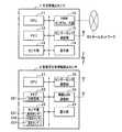
図1は、本発明の実施形態に係る生活見守りシステムの全体の構成を示した図である。図1に示すように、本実施形態に係る生活見守りシステムは、生活者103が生活する居宅100内の各居室101に設置された生活者検出センサ1と、生活者103自身に装着された装着型生体情報検出センサ2と、居宅の一部に適宜設置された設置型生体情報検出センサ3と、居宅の一部に適宜設置された環境異常検出センサ4と、居宅内に設置され、各センサ1〜4が出力する情報に基づき生活者103の生活のイベント情報を取得するホームサーバ5と、生活者103の生活のイベント情報をホームサーバ5から取得し、その生活のイベント情報を生活者イベントDB720に蓄積するセンタサーバ7と、生活者イベントDB720にアクセスして、生活者103の生活のイベント情報を取得して表示するDB閲覧端末8とを含んで構成される。<Overall configuration>
FIG. 1 is a diagram showing an overall configuration of a life watching system according to an embodiment of the present invention. As shown in FIG. 1, the life monitoring system according to the present embodiment includes a
図1において、生活者検出センサ1は、例えば、人感センサを含んで構成され、居宅100内の各居室101や廊下、玄関などに設置される。そして、その人感センサにより、生活者103の所在位置を検出する。また、装着型生体情報検出センサ2は、例えば、腕時計型の脈拍センサであり、主として生活者103の安否に係る情報を取得する。また、設置型生体情報検出センサ3は、例えば、体重計や血圧計であり、主として生活者103の健康に係る情報を取得する。また、環境異常検出センサ4は、例えば、煙センサやガス漏れセンサであり、居宅100内外における環境の異常を検出する。 In FIG. 1, a
これらの各センサ1〜4とホームサーバ5とは、ホームネットワーク50により接続されており、相互の間で情報の送受信を行うことができる。また、ホームサーバ5とセンタサーバ7とは、ネットワーク6により接続されており、相互の間で情報の送受信を行うことができる。また、センタサーバ7とDB閲覧端末8とは、ネットワーク6により接続されており、相互の間で情報の送受信を行うことができる。 Each of these
なお、本実施形態においては、DB閲覧端末8は、例えば、携帯電話機によって構成され、その場合には、DB閲覧端末8は、携帯電話の基地局65を介して、ネットワーク6に接続される。このとき、DB閲覧端末8となる携帯電話機は、メールの着信機能を備えるほか、Webのブラウザ機能とを備えているほうが好ましい。また、Webブラウザ機能を搭載したパソコン、テレビ、PDA(Personal Digital Assistant)などもDB閲覧端末8として利用することができる。なお、本実施形態では、センタサーバ7に接続されているセンタ端末70もDB閲覧端末8として取り扱う。 In the present embodiment, the
<構成の詳細>
次に、図2〜図4を用いて各センサ1〜4、ホームサーバ5およびセンタサーバ7の構成について詳しく説明する。ここで、図2は、本発明の実施形態に係る生活者検出センサおよび装着型生体情報検出センサの構成を示した図、図3は、本発明の実施形態に係るホームサーバの構成を示した図、図4は、本発明の実施形態に係るセンタサーバの構成を示した図である。<Details of configuration>
Next, the configuration of each of the
図2に示すように、生活者検出センサ1は、制御部であるCPU(Central Processing Unit)11と、半導体メモリなどで構成されたメモリ12と、人感センサなどで構成されたセンサ部13と、ホームネットワーク50に接続されるHNW(Home Network)インターフェース部16と、装着型生体情報検出センサ2との間で無線通信をするセンサ−センサ通信部15と、必要に応じて適宜設けられる表示部14とを含んで構成される。 As shown in FIG. 2, the
ここで、ホームネットワーク50は、いわゆる家庭内LAN(Local Area Network)であり、例えば、有線のイーサネット(登録商標)で構成されていても、IEEE802.11規格の無線LANで構成されていてもよい。さらには、その他の仕様の家庭内LANであってもよい。また、センサ−センサ通信部15は、例えば、赤外光による通信部であっても、RFID(Radio Frequency Identification)タグなどで用いられている微弱無線通信の通信部であっても、ブルートゥース仕様の無線通信部であってもよい。 Here, the home network 50 is a so-called home LAN (Local Area Network), and may be configured by, for example, a wired Ethernet (registered trademark) or a wireless LAN of IEEE802.11 standard. . Further, it may be a home LAN with other specifications. The sensor-
装着型生体情報検出センサ2は、制御部であるCPU21と、半導体メモリなどで構成され、ID記憶部221を含むメモリ22と、脈拍センサ231、加速度センサ232、温度センサ233などを適宜含んで構成されたセンサ部23と、生活者検出センサ1との間で無線通信をするセンサ−センサ通信部25と、ホームサーバ5と通信するための無線LAN通信部26と、必要に応じて適宜設けられる表示部24とを含んで構成される。 The wearable biological
ここで、無線LAN通信部26は、例えば、IEEE802.11規格の無線LANに基づく無線通信部であっても、ブルートゥース仕様の無線通信部であっても、さらには他の仕様に基づく無線通信部であってもよい。また、センサ−センサ通信部25は、生活者検出センサ1のセンサ−センサ通信部15に対応して、例えば、赤外光による通信部であっても、RFIDタグなどで用いられている微弱無線通信の通信部であっても、ブルートゥース仕様の無線通信部であってもよい。なお、ここでは、センサ部23に生活者103の脈拍を計測する脈拍センサ231と、体動を検出する加速度センサ322と、体温を検出する温度センサ233とを設けるとしているが、少なくとも生活者の安否を確認するセンサが設けられていればよく、これらのセンサすべてを設ける必要はない。また、逆に、安否を確認するだけでないその他の高度な生体センサが設けられていても構わない。 Here, the wireless
設置型生体情報検出センサ3および環境異常検出センサ4の構成は、図示をしていないが、生活者検出センサ1と同様の構成をしており、その相違は、センサ部13を構成するセンサが異なるだけである。そのセンサの相違により、設置型生体情報検出センサ3および環境異常検出センサ4には多種多様のものがある。例えば、設置型生体情報検出センサ3としては、体重計のほかに、体温計、脈拍計、血圧計、心拍計、心電図計、脳波計、血糖計、尿糖計、活動量計、運動器具に内蔵の消費カロリー計などであってもよい。また、環境異常検出センサ4としては、煙センサやガス漏れセンサのほかに、漏水センサや、地震センサ、泥棒センサなどであってもよい。なお、センサ部13のセンサが異なれば、当然ながら、制御部としてCPU11が処理する内容や表示部14に表示する内容は異なったものとなる。 The configurations of the installed biological
次に、図3に示すようにホームサーバ5は、CPUおよびメモリ(図示せず)からなる情報処理部51と、ハードディスク記憶装置などからなる補助記憶部52と、ネットワーク6に接続されたネットワークインターフェース部53と、ディスプレイ57やキーボード58に接続された入出力インターフェース部54と、ホームネットワーク50に接続されたHNWインターフェース部55と、装着型生体情報検出センサ2と通信するための無線LAN通信部56とを含んで構成される。 Next, as shown in FIG. 3, the home server 5 includes an
ここで、情報処理部51は、各センサ1〜4からホームネットワーク50などを介して入力される生活者103のイベント情報を生成するイベント情報生成処理部511、同様に入力される情報に基づき生活者103の異常状態情報を生成する異常状態情報生成処理部512、ディスプレイ57やキーボード58を用いて入力される情報に基づき閲覧許可情報を生成する閲覧許可情報生成処理部513などのプログラムを含んで構成される。これらのプログラムの処理内容については、別途、詳しく説明する。 Here, the
次に、図4に示すようにセンタサーバ7は、CPUおよびメモリ(図示せず)からなる情報処理部71と、半導体メモリやハードディスク記憶装置などからなる補助記憶部72と、ネットワーク6に接続されたネットワークインターフェース部73と、センタ端末70に接続される入出力インターフェース部74とを含んで構成される。 Next, as shown in FIG. 4, the center server 7 is connected to the network 6, an
ここで、情報処理部71は、生活者イベントDB登録処理部711、生活者イベントDB閲覧処理部712、閲覧許可情報設定処理部713、異常状態緊急度判定処理部714、緊急時情報提供処理部715などのプログラムを含んで構成される。これらのプログラムの処理内容については、別途、詳しく説明する。また、補助記憶部72は、閲覧者ID記憶部721、閲覧許可情報記憶部722、緊急時処置情報記憶部723、緊急度判定情報記憶部724、生活者イベントDB720などを含んで構成される。これらの記憶部に記憶される情報の内容については、後記する。 Here, the
<ホームサーバの処理>
以下、図5〜図9を用い、また、適宜、図1〜図4を参照して、主としてホームサーバ5が実行する処理について説明する。ここで、図5は、本発明の実施形態において、ホームサーバが生活者検出センサから検出データを取得するときの生活者検出センサと装着型生体情報検出センサとホームサーバとの間で行われるデータ送受信の流れを示した図、図6は、ホームサーバにおける異常状態情報生成処理の流れを示した図、図7は、イベント情報および異常状態情報の構成を示した図、図8は、閲覧許可情報生成処理の流れを示した図、図9は、閲覧許可情報の構成を示した図である。<Home server processing>
Hereinafter, processing performed mainly by the home server 5 will be described with reference to FIGS. 5 to 9 and with reference to FIGS. 1 to 4 as appropriate. Here, FIG. 5 illustrates data performed between the consumer detection sensor, the wearable biological information detection sensor, and the home server when the home server acquires detection data from the consumer detection sensor in the embodiment of the present invention. FIG. 6 is a diagram showing a flow of transmission / reception, FIG. 6 is a diagram showing a flow of abnormal state information generation processing in the home server, FIG. 7 is a diagram showing a configuration of event information and abnormal state information, and FIG. FIG. 9 is a diagram showing a flow of information generation processing, and FIG. 9 is a diagram showing a configuration of browsing permission information.
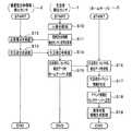
図5に示すように、例えば、人感センサなどを備えた生活者検出センサ1は、人体を検知すると(ステップS10)、装着型生体情報検出センサ2に対して応答を要求する(ステップS11)。その応答要求は、生活者検出センサ1のセンサ−センサ通信部15(図2参照)から微弱な無線電波や赤外光に乗せて出力される。すると、生活者検出センサ1近傍の生活者103が装着している装着型生体情報検出センサ2は、そのセンサ−センサ通信部25により前記応答要求を受信し(ステップS12)、そのID記憶部221に記憶されている生活者103の生活者IDを送信する(ステップS13)。 As shown in FIG. 5, for example, when detecting a human body (step S10), the
生活者検出センサ1は、装着型生体情報検出センサ2から送信された生活者IDを受信し(ステップS14)、受信した生活者IDと、自らに割り当てられたセンサIDと、自らが検出した検出データとを、ホームネットワーク50を介してホームサーバ5へ送信する(ステップS15)。 The
ホームサーバ5は、生活者検出センサ1が送信した生活者ID、センサIDおよび検出データとを受信し(ステップS16)、受信したこれらのデータに基づき、図7(a)に示すような生活者103のイベント情報を生成する(ステップS17)。そして、ホームサーバ5は、その生成したイベント情報をセンタサーバ7へ送信する(ステップS18)とともに、そのイベント情報に基づき生活者103の異常状態を検出する異常状態情報生成処理(詳細後記)を実行する(ステップS19)。 The home server 5 receives the consumer ID, sensor ID and detection data transmitted by the consumer detection sensor 1 (step S16), and based on these received data, the consumer as shown in FIG. 103 event information is generated (step S17). Then, the home server 5 transmits the generated event information to the center server 7 (step S18) and executes an abnormal state information generation process (detailed later) for detecting an abnormal state of the
ホームサーバ5は、設置型生体情報検出センサ3や環境異常検出センサ4からも生活者のイベント情報を取得することができる。この場合にも、そのイベント情報を取得する処理の流れは、図5と同様の処理の流れとなる。つまり、図5において、生活者検出センサ1とあるところを設置型生体情報検出センサ3または環境異常検出センサ4と置き換えるだけでよい。 The home server 5 can also acquire the event information of the consumer from the installed biological
また、装着型生体情報検出センサ2からも生活者のイベント情報を取得することができる。この場合には、装着型生体情報検出センサ2は、そのセンサ部23の例えば加速度センサ232から得られる加速度データに生活者IDとセンサIDとを付してホームサーバ5へ送信すればよい。ただし、その送信データは、有線のホームネットワーク50を経由することはできないので、無線LAN通信部26を介して無線信号に変換され、その無線信号は、ホームサーバ5の無線LAN通信部56で受信される。 In addition, it is possible to acquire consumer event information from the wearable biological
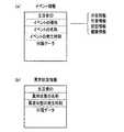
以上のようにして、ホームサーバ5は、生活者103のイベント情報を生成することができる。ここで、図7を参照してイベント情報の構成について説明する。図7(a)に示すように、イベント情報は、生活者IDと、イベントの種別と、イベントの名称と、イベントの発生時刻と、付属データとによって構成される。イベントの種別とは、イベントを種類分けする情報であり、本実施形態では、所在情報、作業情報、状態情報、健康情報などがあるとしている。 As described above, the home server 5 can generate event information of the
ここで、所在情報とは、生活者103がどの居室101にいるかを判断するためのイベント情報であり、例えば、居室101に生活者103が入室したとか、居宅100外へ外出した(玄関ドアなどに設置された人感センサにより検出される)などのイベント情報をいう。また、作業情報とは、生活者103の積極的な行動の記録であり、例えば、電灯を点灯した、テレビのスイッチを入れた、電話をかけたなどのイベント情報をいう。また、状態情報とは、睡眠中、入浴中などの生活者103の状態を示した情報をいう。また、健康情報とは、居宅内にある健康機器(装着型生体情報検出センサ2および設置型生体情報検出センサ3に相当)を利用して、体重を測定した、血圧を測定した、体温を測定した場合などに得られるイベント情報をいう。 Here, the location information is event information for determining which
なお、これらのイベント情報には、イベントの名称ごとに種々の付属データが付属する。例えば、健康情報の場合には、体重測定のイベントには、体重65kgなどのデータが付属し、脈拍測定のイベントには、脈拍数70回/分などのデータが付属する。また、心電図測定や脳波形測定のイベントには、心電波形データや脳波波形データなどの長いデータが付属することもある。 These event information is accompanied by various attached data for each event name. For example, in the case of health information, data such as a weight of 65 kg is attached to a weight measurement event, and data such as a pulse rate of 70 times / minute is attached to a pulse measurement event. In addition, long data such as electrocardiogram waveform data or electroencephalogram waveform data may be attached to an event of electrocardiogram measurement or electroencephalogram measurement.
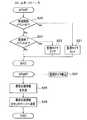
次に、図6に従い、異常状態情報生成処理の処理の流れについて説明する。ホームサーバ5は、図5のステップS17において生成されたイベント情報に基づき、そのイベントが状態開始のイベントであるか否かを判定し、状態開始のイベントであった場合には(ステップS20でYes)、監視タイマをセットする(ステップS21)。また、状態開始のイベントでなかった場合には(ステップS20でNo)、さらに、状態終了のイベントであるか否かを判定し、状態終了のイベントであったときには(ステップS22でYes)、監視タイマをクリアする(ステップS23)。そして、ステップS21、ステップS23を実行後、また、ステップS22でNoの場合には、その処理をいったん終了する。 Next, the flow of the abnormal state information generation process will be described with reference to FIG. The home server 5 determines whether or not the event is a state start event based on the event information generated in step S17 of FIG. 5, and if the event is a state start event (Yes in step S20). ), A monitoring timer is set (step S21). If it is not a state start event (No in step S20), it is further determined whether or not it is a state end event. If it is a state end event (Yes in step S22), monitoring is performed. The timer is cleared (step S23). Then, after executing Step S21 and Step S23, and if No in Step S22, the process is once terminated.
ここで、状態開始のイベントとは、例えば、生活者103が、浴室へ入った、トイレ室へ入ったなどのイベントであり、状態終了のイベントとは、浴室から出た、トイレ室から出たなどのイベントである。これらのイベントにより、例えば、入浴時間やトイレ時間を計測することができ、それらの時間が異常に長い場合には、異常状態と判定する。本実施形態では、監視タイマが時間計測を行い、監視タイマが所定の時間に達すると、情報処理部51に対して割り込みを発生させる。 Here, the state start event is, for example, an event in which the
そこで、監視タイマからの割り込みが発生すると(ステップS24)、ホームサーバ5は、再び、異常状態情報生成処理の実行を開始し、前記の状態開始イベントの情報に基づき、異常状態情報(例えば、入浴時間が長過ぎるなどの情報)を生成する(ステップS25)。そして、ホームサーバ5は、その生成した異常状態情報をセンタサーバ7へ送信する(ステップS26)。このとき、異常状態情報は、図7(b)に示すように、生活者IDと、異常状態の名称と、異常状態の発生時刻と、付属データとによって構成される。 Therefore, when an interruption from the monitoring timer occurs (step S24), the home server 5 starts again the execution of the abnormal state information generation process, and abnormal state information (for example, bathing) is started based on the information of the state start event. Information such as time is too long) (step S25). Then, the home server 5 transmits the generated abnormal state information to the center server 7 (step S26). At this time, as shown in FIG. 7B, the abnormal state information includes a consumer ID, a name of the abnormal state, an occurrence time of the abnormal state, and attached data.
以上のように、本実施形態においては、イベント情報および異常状態情報の各々には、生活者IDが付されているので、居宅100において複数の生活者103が生活していたとしても、ホームサーバ5は、その各々の生活者103を識別して、そのイベント情報を取得することができる。 As described above, in the present embodiment, since each of the event information and the abnormal state information is assigned with a consumer ID, even if a plurality of
なお、生活者IDを持たない来客があった場合には、生活者検出センサ1は、生活者IDを取得することができない。そのような場合には、生活者IDとして来客者用IDを割り当てるようにすればよい。また、留守中などに煙センサなどの環境異常検出センサ4などが作動した場合にも、その環境異常検出センサ4は、生活者IDを取得することができない。このような場合には、生活者IDとして留守IDなどを割り当てるようにすればよい。 In addition, when there is a visitor who does not have a consumer ID, the
次に、図8および図9に従い、閲覧許可情報生成処理について説明する。本実施形態においては、生活者103がホームサーバ5を操作して閲覧許可情報を作成する。そこで、生活者103は、ホームサーバ5に対し、まず、キーボード58などから所定のコマンドを入力することにより、閲覧許可情報生成処理のプログラムを起動する。すると、ホームサーバ5は、ディスプレイ57に閲覧許可情報の作成画面を表示する(ステップS30)。生活者103は、その画面を見て必要事項を入力するので、ホームサーバ5は、その閲覧許可情報の入力データを取り込み(ステップS31)、取り込んだ閲覧許可情報をセンタサーバ7へ送信する(ステップS32)。 Next, the browsing permission information generation process will be described with reference to FIGS. In this embodiment, the
図9(a)は、ある生活者103に関する閲覧許可情報の例である。本実施形態においては、その生活者103の生活者イベント情報および異常状態情報を、閲覧者ごと、かつ、イベントの種別(図7参照)ごとに設定することができる。そこで、ステップS30においては、例えば、図9(a)のような表示がなされるので、生活者103は、各閲覧者に対し、その閲覧許可情報を設定すればよい。 FIG. 9A is an example of browsing permission information regarding a
ここで、“○”は、閲覧許可、“−”は、閲覧不可を示している。例えば、近くに住んでいる長女にはすべての情報が閲覧できるように設定し、遠くに住んでいる長男には、どの居室101にいるかなどの所在情報は閲覧させない設定としている。また、センタのオペレータや隣人に対しては、異常状態情報については閲覧が可能であるが、他の情報についてはプライバシ保護のために閲覧させない設定としている。ただし、隣人に対しては、所在情報を閲覧できる設定にしている。 Here, “◯” indicates that browsing is permitted, and “−” indicates that browsing is not possible. For example, the eldest daughter living nearby is set to be able to browse all information, and the eldest son living far away is set not to browse the location information such as in which
なお、図9では、閲覧許可の設定をイベントの種別ごと設定するとしているが、さらに、細分化した項目に対して閲覧許可を設定するようにしてもよい。例えば、健康情報については、体重を測定したなどのイベントだけの情報と、そのイベントに付属する、例えば、65kgなどの付属データとに分けて閲覧許可を設定してもよい。そのほうが、より木目細かにプライバシを保護することができる。また、心電波形などの長大で専門性があるような付属データが付属する場合には、その長大なデータを必要以上に送信することを防ぐことができる。 In FIG. 9, the browsing permission setting is set for each event type, but the browsing permission may be set for further subdivided items. For example, with regard to health information, browsing permission may be set separately for information only about events such as measuring body weight and attached data such as 65 kg attached to the event. This can protect the privacy more finely. In addition, when attached large and specialized attached data such as an electrocardiographic waveform is attached, it is possible to prevent the large data from being transmitted more than necessary.
本実施形態においては、以上のように、生活者103自らが自らのイベント情報および異常状態情報の閲覧許可を設定できるようにしている。そのため、生活者103を十分に保護することができる。しかしながら、これでは緊急時には不都合が生じる。そのため、本実施形態では、図9(b)に示すように緊急時の閲覧許可情報を準備する。そして、この場合には、ほとんどの情報を閲覧可能なように設定しておく。 In the present embodiment, as described above, the
この緊急時の閲覧許可情報も、通常時の閲覧許可情報と同様に生活者103自らが設定できるようにしておいてもよい。ただし、その場合には、例えば、センタのオペレータに対する閲覧許可情報は、全部閲覧できるように設定し、生活者103は、その設定を変更できないとする。 The emergency browsing permission information may also be set by the
<センタサーバの処理>
次に、図10〜図13を用い、また、適宜、図1〜図4を参照して、センタサーバ7が実行する処理について説明する。ここで、図10は、生活者イベントDB閲覧処理部の処理の流れを示した図、図11は、異常状態緊急度判定処理部および緊急時情報提供処理部の処理の流れを示した図、図12は、緊急度判定情報の例を示した図、図13は、緊急時処理情報の例を示した図である。<Center server processing>
Next, processing executed by the center server 7 will be described with reference to FIGS. 10 to 13 and with reference to FIGS. 1 to 4 as appropriate. Here, FIG. 10 is a diagram showing a process flow of the consumer event DB browsing processing unit, and FIG. 11 is a diagram showing a process flow of the abnormal state emergency degree determination processing unit and the emergency information provision processing unit. FIG. 12 is a diagram illustrating an example of emergency level determination information, and FIG. 13 is a diagram illustrating an example of emergency process information.
まず、図4を参照して、センタサーバ7の情報処理部71の各処理部711について説明する。生活者イベントDB登録処理部711は、ホームサーバ5から送信される生活者103のイベント情報および異常状態情報を受信し、その受信したイベント情報および異常状態情報を生活者イベントDB720に登録する処理を実行する。このとき、生活者イベントDB720には、イベント情報および異常状態情報は、生活者IDおよびイベントの種別ごとに分類されて登録される。また、閲覧者許可情報設定処理部713は、ホームサーバ5から送信される閲覧者許可情報を受信し、その受信した閲覧者許可情報を閲覧許可情報記憶部722に設定する処理を実行する。 First, the
生活者イベントDB閲覧処理部712の処理の流れについては、図10に従って説明する。まず、DB閲覧端末8から、DB閲覧要求情報が送信される(ステップS41)。そこで、センタサーバ7の情報処理部71は、そのDB閲覧要求情報を受信する(ステップS42)。そのDB閲覧要求情報には、閲覧者IDや閲覧しようとしている生活者IDなどが含まれているので、その閲覧者IDおよび生活者IDに基づき、閲覧許可情報記憶部722に記憶されている閲覧許可情報を参照して、その閲覧者が閲覧可能な生活者イベントDB720の情報の種別を取得する(ステップS43)。 The process flow of the consumer event DB
情報処理部71は、次に、ステップS43で取得された情報の種別が指示する情報を、生活者イベントDB720から取得し(ステップS44)、その取得した生活者イベントDB720の情報をDB閲覧端末8へ送信する(ステップS45)。DB閲覧端末8は、その生活者イベントDB720の情報を受信し(ステップS46)、DB閲覧端末8に付属する表示装置などにその受信した生活者イベントDB720の情報を表示する(ステップS47)。このようにして、閲覧者は、指定した生活者のイベント情報を閲覧することができる。 Next, the
次に、図11に従って異常状態緊急度判定処理部および緊急時情報提供処理部の処理の流れについて説明する。センタサーバ7の情報処理部71は、ホームサーバ5から送信される異常状態情報を受信すると(ステップS50)、緊急度判定情報記憶部724に記憶されている緊急度判定情報を参照して、受信した異常状態情報の緊急度を判定する(ステップS51)。 Next, the processing flow of the abnormal state urgency determination processing unit and the emergency information provision processing unit will be described with reference to FIG. When the
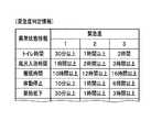
ここで、緊急度判定情報の例を図12に示す。図12に示すように、例えば、入浴時間が1時間以上であれば、緊急度“1”とし、2時間以上であれば緊急度“2”とし、3時間以上あれば、緊急度“3”とする。なお、ここでは緊急度は3レベルあるとしているが、何レベルあっても構わない。 Here, an example of the emergency determination information is shown in FIG. As shown in FIG. 12, for example, if the bathing time is 1 hour or more, the urgency is “1”, if it is 2 hours or more, the urgency is “2”, and if it is 3 hours or more, the urgency is “3”. And Here, there are three levels of urgency, but any number of levels may be used.
そして、その緊急度が所定の緊急度よりも高い場合、例えば、緊急度が“3”になった場合には(ステップS52でYes)、生活者103に緊急事態が発生したと判断して、閲覧許可情報記憶部722に記憶されている閲覧許可情報を、緊急時の閲覧許可情報に変更する(ステップS53)。そして、緊急時処置情報記憶部723に記憶されている緊急時処理情報に基づき異常状態情報を指定されたDB閲覧端末8へ送信する(ステップS54)。 When the urgency level is higher than the predetermined urgency level, for example, when the urgency level is “3” (Yes in step S52), it is determined that an emergency has occurred in the
ここで、緊急時処理情報の例を図13に示す。図13に示すように、緊急時には、例えば、長女には緊急であることを通知するメールを、例えば、携帯電話である長女のDB閲覧端末8へ送信する。その場合、そのメールには、異常状態の情報が添付されるが、他の情報は添付されない。そこで、見守り対象の生活者103の状態が緊急であることの通知を受けた、例えば、長女は、DB閲覧端末8によって生活者イベントDB720をアクセスし、その生活者103の詳しい状況を取得することができる。 Here, FIG. 13 shows an example of emergency processing information. As shown in FIG. 13, in an emergency, for example, an email notifying the eldest daughter of an emergency is transmitted to the eldest daughter's
また、同様の通知は、センタのオペレータにも送信されるので、オペレータは、通常は閲覧できない生活者のイベント情報を閲覧して、緊急事態の状況を把握して、次の処置、例えば、現場に救援者を派遣するとか、救急車を呼ぶとかの指示を出すことができる。 In addition, since a similar notification is also sent to the operator at the center, the operator browses the event information of consumers who cannot normally browse, grasps the situation of the emergency situation, and performs the next action, for example, the site. You can give instructions such as dispatching a rescuer or calling an ambulance.
以上のように、本実施形態によれば、通常時は、見守りの対象である生活者103の意のままに閲覧許可情報を設定できるので、生活者103のプライバシが保護され、また、緊急時には、その閲覧許可範囲が拡大されたような緊急時の閲覧許可情報が使用されるので、例えば、センタのオペレータが生活者103のイベント情報を閲覧できないような不都合を回避することができる。 As described above, according to the present embodiment, since the browsing permission information can be set as intended by the
1 生活者検出センサ
2 装着型生体情報検出センサ
3 設置型生体情報検出センサ(第2の生体情報検出センサ)
4 環境異常検出センサ
5 ホームサーバ
6 ネットワーク
7 センタサーバ
8 DB閲覧端末
50 ホームネットワーク
65 基地局
70 センタ端末
100 居宅
101 居室
103 生活者
720 生活者イベントDBDESCRIPTION OF
4 Environmental Anomaly Detection Sensor 5 Home Server 6 Network 7
Claims (10)
Translated fromJapanese前記ホームサーバが、前記生活者検出センサおよび前記生体情報検出センサの出力情報に基づき前記生活者ID付きイベント情報を生成し、前記生成した前記生活者ID付きイベント情報を前記センタサーバへ送信するステップと、
前記ホームサーバが、前記生成した前記生活者ID付きイベント情報に基づき、前記生活者の異常状態を検出し、前記検出した前記生活者の異常状態の情報を前記センタサーバへ送信するステップと、
前記センタサーバが、前記ホームサーバから送信された前記生活者ID付きイベント情報と前記生活者の異常状態の情報とを受信し、前記受信した前記生活者ID付きイベント情報と前記生活者の異常状態の情報とを前記生活者イベントDBへ蓄積するステップと、
前記センタサーバが、前記DB閲覧端末から前記生活者イベントDBの閲覧要求情報と閲覧者IDとを受信したときには、前記閲覧要求情報が指示する前記生活者イベントDBの情報のうち、前記閲覧者IDごとにあらかじめ設定されている閲覧許可情報の範囲内の情報を、前記DB閲覧端末へ送信するステップと
を備えることを特徴とする生活見守り方法。Installed in a home where at least one consumer lives, a consumer detection sensor that detects the location of the consumer, and attached to the consumer to detect at least one biological information and output a consumer ID A living body information detecting sensor, a home server connected to the living person detecting sensor and the living body information detecting sensor, collecting event information of the behavior of the living person, connected to the home server via a network, and A center server provided with a consumer event DB that stores event information of a person's behavior, and a DB browsing terminal that is connected to the center server via a network and browses information stored in the consumer event DB. A life monitoring method in the life monitoring system,
The home server generates the event information with the consumer ID based on the output information of the consumer detection sensor and the biological information detection sensor, and transmits the generated event information with the consumer ID to the center server. When,
The home server detects the abnormal state of the consumer based on the generated event information with the consumer ID, and transmits the detected abnormal state information of the consumer to the center server;
The center server receives the event information with the consumer ID transmitted from the home server and the information on the abnormal state of the consumer, and the received event information with the consumer ID and the abnormal state of the consumer And storing the information in the consumer event DB;
When the center server receives the browsing request information and the browsing ID of the consumer event DB from the DB browsing terminal, the browsing ID is included in the information of the consumer event DB indicated by the browsing request information. Transmitting the information within the range of the browsing permission information set in advance for each to the DB browsing terminal.
前記センタサーバが、前記ホームサーバから送信された前記閲覧許可情報を受信し、前記受信した前記閲覧許可情報に基づき自らが保持する前記閲覧許可情報を変更するステップと
を、さらに、備えることを特徴とする請求項1に記載の生活見守り方法。The home server sets the browsing permission information for each browser ID based on information input by the consumer, and transmits the set browsing permission information to the center server;
The center server further receiving the browsing permission information transmitted from the home server, and changing the browsing permission information held by itself based on the received browsing permission information. The life watching method according to claim 1.
を、さらに、備えることを特徴とする請求項1または請求項2に記載の生活見守り方法。When the center server receives the information on the abnormal state of the consumer transmitted from the home server, the center server determines the urgency of the response to the received abnormal state of the consumer, and the urgency is The method further comprises the steps of transmitting information including information on the abnormal state to a predetermined DB browsing terminal and changing the browsing permission information when the emergency level is higher than a predetermined level of urgency. Or the life watching method of Claim 2.
を特徴とする請求項1ないし請求項3のいずれか一項に記載の生活見守り方法。The home server is further connected to a second biological information detection sensor installed in the home, and generates event information on the behavior of the consumer based on output information of the second biological information detection sensor. The life monitoring method according to any one of claims 1 to 3, wherein:
を特徴とする請求項1ないし請求項4のいずれか一項に記載の生活見守り方法。When the home server is further connected to an environmental abnormality detection sensor installed in the home and detects an environmental abnormality in the home based on the output of the environmental abnormality detection sensor, the detected environmental abnormality The life monitoring method according to any one of claims 1 to 4, wherein the information is transmitted to the center server as information on an abnormal state of the consumer.
前記ホームサーバが、
前記生活者検出センサおよび前記生体情報検出センサの出力情報に基づき前記生活者の行動の前記生活者ID付きイベント情報を生成し、前記生成した前記生活者ID付きイベント情報を前記センタサーバへ送信し、
前記生成した前記生活者ID付きイベント情報に基づき、前記生活者の異常状態を検出し、前記検出した前記生活者の異常状態の情報を前記センタサーバへ送信し、
前記センタサーバが、
前記ホームサーバから送信された前記生活者ID付きイベント情報と前記生活者の異常状態の情報とを受信し、前記受信した前記生活者ID付きイベント情報と前記生活者の異常状態の情報とを前記生活者イベントDBへ蓄積し、
前記DB閲覧端末から前記生活者イベントDBの閲覧要求情報と閲覧者IDとを受信したときには、前記閲覧要求情報が指示する前記生活者イベントDBの情報のうち、前記閲覧者IDごとにあらかじめ設定されている閲覧許可情報の範囲内の情報を、前記DB閲覧端末へ送信すること
を特徴とする生活見守りシステム。Installed in a home where at least one consumer lives, a consumer detection sensor that detects the location of the consumer, and attached to the consumer to detect at least one biological information and output a consumer ID A living body information detecting sensor, a home server connected to the living person detecting sensor and the living body information detecting sensor, collecting event information of the behavior of the living person, connected to the home server via a network, and A center server provided with a consumer event DB that stores event information of a person's behavior, and a DB browsing terminal that is connected to the center server via a network and browses information stored in the consumer event DB. A life monitoring system,
The home server is
Based on output information of the consumer detection sensor and the biological information detection sensor, the event information with the consumer ID of the behavior of the consumer is generated, and the generated event information with the consumer ID is transmitted to the center server. ,
Based on the generated event information with the consumer ID, the abnormal state of the consumer is detected, and the detected abnormal state information of the consumer is transmitted to the center server,
The center server is
The event information with the consumer ID transmitted from the home server and the information on the abnormal state of the consumer are received, and the received event information with the consumer ID and the information on the abnormal state of the consumer are Accumulate in the consumer event database,
When the browsing request information and the viewer ID of the consumer event DB are received from the DB browsing terminal, the information is set in advance for each viewer ID among the information of the consumer event DB indicated by the browsing request information. The life monitoring system is characterized in that information within the range of the browsing permission information is transmitted to the DB browsing terminal.
前記ホームサーバが、前記生活者によって入力される情報に基づき前記閲覧者IDごとに前記閲覧許可情報を設定し、前記設定した前記閲覧許可情報を前記センタサーバへ送信し、
前記センタサーバが、さらに、前記ホームサーバから送信された前記閲覧許可情報を受信し、前記受信した前記閲覧許可情報に基づき自らが保持する前記閲覧許可情報を変更すること
を特徴とする生活見守りシステム。The life monitoring system according to claim 6, further comprising:
The home server sets the browsing permission information for each browser ID based on information input by the consumer, and transmits the set browsing permission information to the center server.
The center server further receives the browsing permission information transmitted from the home server, and changes the browsing permission information held by itself based on the received browsing permission information. .
前記センタサーバが、前記ホームサーバから送信された前記生活者の異常状態の情報を受信した場合には、さらに、前記受信した前記生活者の異常状態への対応の緊急度を判定し、その緊急度が所定の緊急度よりも高かったときには、前記異常状態の情報を含む情報を所定のDB閲覧端末へ送信するとともに、前記閲覧許可情報を変更する
ことを特徴とする生活見守りシステム。The life monitoring system according to claim 6 or 7, further comprising:
When the center server receives the information on the abnormal state of the consumer transmitted from the home server, the center server further determines the urgency of the response to the received abnormal state of the consumer, and the emergency When the degree is higher than a predetermined urgency level, information including the abnormal state information is transmitted to a predetermined DB browsing terminal, and the browsing permission information is changed.
を特徴とする請求項6ないし請求項8のいずれか一項に記載の生活見守りシステム。The home server is further connected to a second biological information detection sensor installed in the home, and generates event information on the behavior of the consumer based on output information of the second biological information detection sensor. The life monitoring system according to any one of claims 6 to 8, characterized by:
を特徴とする請求項6ないし請求項9のいずれか一項に記載の生活見守りシステム。When the home server is further connected to an environmental abnormality detection sensor installed in the home and detects an environmental abnormality in the home based on the output of the environmental abnormality detection sensor, the detected environmental abnormality The life monitoring system according to any one of claims 6 to 9, wherein the information is transmitted to the center server as information on an abnormal state of the consumer.
Priority Applications (1)
| Application Number | Priority Date | Filing Date | Title |
|---|---|---|---|
| JP2004339660AJP4469262B2 (en) | 2004-11-24 | 2004-11-24 | Life monitoring system |
Applications Claiming Priority (1)
| Application Number | Priority Date | Filing Date | Title |
|---|---|---|---|
| JP2004339660AJP4469262B2 (en) | 2004-11-24 | 2004-11-24 | Life monitoring system |
Publications (3)
| Publication Number | Publication Date |
|---|---|
| JP2006146827Atrue JP2006146827A (en) | 2006-06-08 |
| JP2006146827A5 JP2006146827A5 (en) | 2007-09-06 |
| JP4469262B2 JP4469262B2 (en) | 2010-05-26 |
Family
ID=36626406
Family Applications (1)
| Application Number | Title | Priority Date | Filing Date |
|---|---|---|---|
| JP2004339660AExpired - LifetimeJP4469262B2 (en) | 2004-11-24 | 2004-11-24 | Life monitoring system |
Country Status (1)
| Country | Link |
|---|---|
| JP (1) | JP4469262B2 (en) |
Cited By (10)
| Publication number | Priority date | Publication date | Assignee | Title |
|---|---|---|---|---|
| JP2008040761A (en)* | 2006-08-04 | 2008-02-21 | Teruya:Kk | Disease sign management service |
| JP2012221386A (en)* | 2011-04-13 | 2012-11-12 | Toshiba Corp | Home healthcare system and biological information management program |
| JP2014089494A (en)* | 2012-10-29 | 2014-05-15 | System Craft Inc | Resident watching device, resident watching program, and resident watching method |
| JP2015156097A (en)* | 2014-02-20 | 2015-08-27 | ビッグローブ株式会社 | monitoring information browsing system, communication terminal, control device, information browsing control method and program |
| KR101559391B1 (en)* | 2014-12-04 | 2015-10-12 | (주)정우솔루션 | Management system for toilet of lockup |
| WO2016199457A1 (en)* | 2015-06-12 | 2016-12-15 | ソニー株式会社 | Information processing device, information processing method, and program |
| JP2017097420A (en)* | 2015-11-18 | 2017-06-01 | 株式会社日立ビルシステム | Maintenance person position information confirmation system and maintenance person position information confirmation method applied to the same |
| JP2018147452A (en)* | 2017-03-09 | 2018-09-20 | 岩崎通信機株式会社 | Door system and monitoring method using door system |
| JP2019159714A (en)* | 2018-03-12 | 2019-09-19 | 公立大学法人岩手県立大学 | Information collection system, information collection method, and program |
| JP7235089B1 (en) | 2021-10-05 | 2023-03-08 | トヨタ自動車株式会社 | Data management device, data management method and input terminal |
Families Citing this family (2)
| Publication number | Priority date | Publication date | Assignee | Title |
|---|---|---|---|---|
| CN105147306A (en)* | 2015-03-07 | 2015-12-16 | 沈阳体育学院 | Taijiquan fitness intelligent service platform |
| CN110491089B (en)* | 2019-08-12 | 2021-08-13 | 首都医科大学 | An elderly care system based on neural reflex |
Citations (4)
| Publication number | Priority date | Publication date | Assignee | Title |
|---|---|---|---|---|
| JPH1085192A (en)* | 1996-09-18 | 1998-04-07 | Matsushita Electric Ind Co Ltd | Emergency support system for home care recipients |
| JP2002109667A (en)* | 2000-10-04 | 2002-04-12 | Sekisui Chem Co Ltd | Management device for life watching |
| JP2004102913A (en)* | 2002-09-12 | 2004-04-02 | Fuji Xerox Co Ltd | Personal information managing system and method therefor |
| JP2004133777A (en)* | 2002-10-11 | 2004-04-30 | Sompo Japan Insurance Inc | Device and method for monitoring life of person to be monitored, device and method for tracking the person, computer program and recording medium |
- 2004
- 2004-11-24JPJP2004339660Apatent/JP4469262B2/ennot_activeExpired - Lifetime
Patent Citations (4)
| Publication number | Priority date | Publication date | Assignee | Title |
|---|---|---|---|---|
| JPH1085192A (en)* | 1996-09-18 | 1998-04-07 | Matsushita Electric Ind Co Ltd | Emergency support system for home care recipients |
| JP2002109667A (en)* | 2000-10-04 | 2002-04-12 | Sekisui Chem Co Ltd | Management device for life watching |
| JP2004102913A (en)* | 2002-09-12 | 2004-04-02 | Fuji Xerox Co Ltd | Personal information managing system and method therefor |
| JP2004133777A (en)* | 2002-10-11 | 2004-04-30 | Sompo Japan Insurance Inc | Device and method for monitoring life of person to be monitored, device and method for tracking the person, computer program and recording medium |
Cited By (11)
| Publication number | Priority date | Publication date | Assignee | Title |
|---|---|---|---|---|
| JP2008040761A (en)* | 2006-08-04 | 2008-02-21 | Teruya:Kk | Disease sign management service |
| JP2012221386A (en)* | 2011-04-13 | 2012-11-12 | Toshiba Corp | Home healthcare system and biological information management program |
| JP2014089494A (en)* | 2012-10-29 | 2014-05-15 | System Craft Inc | Resident watching device, resident watching program, and resident watching method |
| JP2015156097A (en)* | 2014-02-20 | 2015-08-27 | ビッグローブ株式会社 | monitoring information browsing system, communication terminal, control device, information browsing control method and program |
| KR101559391B1 (en)* | 2014-12-04 | 2015-10-12 | (주)정우솔루션 | Management system for toilet of lockup |
| WO2016199457A1 (en)* | 2015-06-12 | 2016-12-15 | ソニー株式会社 | Information processing device, information processing method, and program |
| JP2017097420A (en)* | 2015-11-18 | 2017-06-01 | 株式会社日立ビルシステム | Maintenance person position information confirmation system and maintenance person position information confirmation method applied to the same |
| JP2018147452A (en)* | 2017-03-09 | 2018-09-20 | 岩崎通信機株式会社 | Door system and monitoring method using door system |
| JP2019159714A (en)* | 2018-03-12 | 2019-09-19 | 公立大学法人岩手県立大学 | Information collection system, information collection method, and program |
| JP7235089B1 (en) | 2021-10-05 | 2023-03-08 | トヨタ自動車株式会社 | Data management device, data management method and input terminal |
| JP2023055133A (en)* | 2021-10-05 | 2023-04-17 | トヨタ自動車株式会社 | Data management device, data management method and input terminal |
Also Published As
| Publication number | Publication date |
|---|---|
| JP4469262B2 (en) | 2010-05-26 |
Similar Documents
| Publication | Publication Date | Title |
|---|---|---|
| US7394385B2 (en) | Comprehensive monitoring system | |
| JP4487730B2 (en) | Life status notification system | |
| JP6091842B2 (en) | Resident monitoring device, resident monitoring program and resident monitoring method | |
| US20140327540A1 (en) | Mobile personal emergency response system | |
| US20070106124A1 (en) | Safety check system, method, and program, and memory medium for memorizing program therefor | |
| WO2014148037A1 (en) | Lifestyle care assisting device | |
| JP4469262B2 (en) | Life monitoring system | |
| KR102285597B1 (en) | Wearable terminal and system for supporting nursing care using the same | |
| JP6711474B2 (en) | System, system control method, control program, and device including program | |
| WO2020003706A1 (en) | Control program, report output method, and report output device | |
| JP4058310B2 (en) | Sleep state determination device and bedtime monitoring system | |
| KR20180106583A (en) | Care device and care system for the old and the infrim | |
| WO2020003758A1 (en) | Report output program, report output method, and report output device | |
| JP6680563B2 (en) | Watching system and watching method | |
| JP7259540B2 (en) | Determination device, control program for determination device, and determination method | |
| WO2022264592A1 (en) | Sensor device, system, and transmission method | |
| JP7570608B1 (en) | A management system for managing biometric information broadcast from wearable devices | |
| JP7327396B2 (en) | Control program, report output method, and report output device | |
| JP2006092257A (en) | Care support system and method | |
| WO2017195839A1 (en) | Monitored person monitoring system, terminal device, and monitored person monitoring method | |
| JP2014092945A (en) | Physical condition determination system and physical condition determination method | |
| JP2014092946A (en) | Personal information disclosure system and personal information disclosure method | |
| KR20050090947A (en) | System for silver-tel | |
| JP4206051B2 (en) | Safety confirmation system, safety confirmation method, safety confirmation program, and storage medium storing the program | |
| JP6908028B2 (en) | Observer monitoring device, method, system and program |
Legal Events
| Date | Code | Title | Description |
|---|---|---|---|
| A521 | Request for written amendment filed | Free format text:JAPANESE INTERMEDIATE CODE: A523 Effective date:20070724 | |
| A621 | Written request for application examination | Free format text:JAPANESE INTERMEDIATE CODE: A621 Effective date:20070724 | |
| A977 | Report on retrieval | Free format text:JAPANESE INTERMEDIATE CODE: A971007 Effective date:20091119 | |
| A131 | Notification of reasons for refusal | Free format text:JAPANESE INTERMEDIATE CODE: A131 Effective date:20091201 | |
| A521 | Request for written amendment filed | Free format text:JAPANESE INTERMEDIATE CODE: A523 Effective date:20100126 | |
| TRDD | Decision of grant or rejection written | ||
| A01 | Written decision to grant a patent or to grant a registration (utility model) | Free format text:JAPANESE INTERMEDIATE CODE: A01 Effective date:20100223 | |
| A01 | Written decision to grant a patent or to grant a registration (utility model) | Free format text:JAPANESE INTERMEDIATE CODE: A01 | |
| A61 | First payment of annual fees (during grant procedure) | Free format text:JAPANESE INTERMEDIATE CODE: A61 Effective date:20100226 | |
| R150 | Certificate of patent or registration of utility model | Ref document number:4469262 Country of ref document:JP Free format text:JAPANESE INTERMEDIATE CODE: R150 Free format text:JAPANESE INTERMEDIATE CODE: R150 | |
| FPAY | Renewal fee payment (event date is renewal date of database) | Free format text:PAYMENT UNTIL: 20130305 Year of fee payment:3 | |
| FPAY | Renewal fee payment (event date is renewal date of database) | Free format text:PAYMENT UNTIL: 20130305 Year of fee payment:3 | |
| EXPY | Cancellation because of completion of term |