JP2006146668A - Operation management support apparatus and operation management support program - Google Patents
Operation management support apparatus and operation management support programDownload PDFInfo
- Publication number
- JP2006146668A JP2006146668AJP2004337411AJP2004337411AJP2006146668AJP 2006146668 AJP2006146668 AJP 2006146668AJP 2004337411 AJP2004337411 AJP 2004337411AJP 2004337411 AJP2004337411 AJP 2004337411AJP 2006146668 AJP2006146668 AJP 2006146668A
- Authority
- JP
- Japan
- Prior art keywords
- model
- operation information
- information
- statistical analysis
- management support
- Prior art date
- Legal status (The legal status is an assumption and is not a legal conclusion. Google has not performed a legal analysis and makes no representation as to the accuracy of the status listed.)
- Withdrawn
Links
- 238000007619statistical methodMethods0.000claimsabstractdescription43
- 238000012545processingMethods0.000claimsdescription27
- 238000012360testing methodMethods0.000claimsdescription21
- 238000000513principal component analysisMethods0.000claimsdescription9
- 238000007781pre-processingMethods0.000abstractdescription17
- 230000006866deteriorationEffects0.000abstractdescription8
- 238000000034methodMethods0.000description37
- 230000000875corresponding effectEffects0.000description34
- 239000011159matrix materialSubstances0.000description21
- 238000012544monitoring processMethods0.000description11
- 238000010586diagramMethods0.000description8
- 230000002159abnormal effectEffects0.000description6
- 230000015556catabolic processEffects0.000description6
- 238000006731degradation reactionMethods0.000description6
- 230000005856abnormalityEffects0.000description4
- 238000004519manufacturing processMethods0.000description4
- 238000004891communicationMethods0.000description3
- 230000007423decreaseEffects0.000description3
- 238000001514detection methodMethods0.000description3
- 238000010219correlation analysisMethods0.000description2
- 230000001960triggered effectEffects0.000description2
- 238000004458analytical methodMethods0.000description1
- 230000005540biological transmissionEffects0.000description1
- 239000000470constituentSubstances0.000description1
- 230000002596correlated effectEffects0.000description1
- 238000005314correlation functionMethods0.000description1
- 230000003247decreasing effectEffects0.000description1
- 238000013461designMethods0.000description1
- 238000007689inspectionMethods0.000description1
- 238000005259measurementMethods0.000description1
- 230000002093peripheral effectEffects0.000description1
- 238000000926separation methodMethods0.000description1
- 238000013179statistical modelMethods0.000description1
- 238000012546transferMethods0.000description1
- 238000012795verificationMethods0.000description1
Images


Landscapes
- Debugging And Monitoring (AREA)
Abstract
Description
Translated fromJapanese本発明は、ネットワークシステム等のシステムの運用管理を支援するために用いて好適な運用管理支援装置及び運用管理支援プログラムに関する。 The present invention relates to an operation management support apparatus and an operation management support program suitable for use in supporting operation management of a system such as a network system.
従来の運用管理では、監視対象の各サーバやネットワーク機器のハードウェア的な稼動情報や、各プログラムが動作しているかという情報を収集し、システムの構成要素ごとのアラートや稼動情報の提示を行っている。例えば、特許文献1に記載されている装置では、データベースに事前定義された一定範囲の条件を満たす運用状況が発生したときにアラートを発するようにしている。また、この装置では、収集した情報に基づいて性能劣化の到達予想を直線・曲線近似によって提示できるようになっている。ただし、この装置では、定義外の異常障害は基本的に考慮されていない。すなわち、監視対象の各構成要素の稼動情報に対して一定の値の範囲を予め定義し、その範囲に入るかまたは外れるかということを検出することで性能劣化状態が判定されるようになっていた。また、この装置では、検知した結果に基づいて予め定義されているものに関して、相関分析によって原因を絞り込み、対応する対策が表示されるようになっていた。 Conventional operation management collects hardware operation information of each monitored server and network device and information on whether each program is operating, and presents alerts and operation information for each system component. ing. For example, in the apparatus described in Patent Document 1, an alert is issued when an operation situation that satisfies a certain range of conditions predefined in a database occurs. Also, with this apparatus, it is possible to present the expected arrival of performance degradation based on the collected information by linear / curve approximation. However, this device basically does not consider abnormal faults that are not defined. That is, a range of a certain value is defined in advance for the operation information of each component to be monitored, and the performance deterioration state is determined by detecting whether the value falls within or outside the range. It was. Further, in this apparatus, the cause is narrowed down by correlation analysis for the ones that are predefined based on the detected result, and the corresponding countermeasures are displayed.
一方、特許文献2に記載されている装置では、正常動作からの外れ値を検知することで、性能劣化が判定されるようになっている。測定値から導かれる制御量(を基にしたデータ)と動作を行う操作量(を基にしたデータ)の相関を取り、検定を行うことで、性能劣化状態を検知している。ただし、各構成要素のデータは取得していないので、性能劣化の原因や対策を判断することはできなかった。
システムに障害が発生したときには、管理者がシステムの構成要素ごとのアラートや稼動情報から、システムの状況を推定・想像したり、あらかじめ定義したマニュアルに従って対応を行う。前者は、管理者のスキルに依存する部分が大きいため、障害、性能低下の改善に時間を要したり、人為的なミスによる2次被害の可能性があったりする。後者は条件の定義が厳密であるため、取得値が定義には含まれないが危険な兆候である場合などのケースでは、対応がとれなかったり、誤った対応を行ってしまったりするという問題点がある。 When a failure occurs in the system, the administrator estimates and imagines the system status from alerts and operation information for each component of the system and responds according to a predefined manual. Since the former largely depends on the skill of the manager, it takes time to improve failures and performance degradation, and there is a possibility of secondary damage due to human error. In the latter case, the definition of the condition is strict, so in cases such as when the acquired value is not included in the definition but it is a dangerous sign, it is not possible to take a response, or an incorrect response is made There is.
特許文献1に記載されている装置では、劣化の数値範囲・原因・対策が事前定義され、その範囲内において検出と対策を示すことができ、また、範囲外となる場合には、数値を直線・曲線で予測するのみで各構成要素の関連性などは考慮されていなかった。そのため、事前定義外の状況には対応しきれない場合が発生すると考えられる。 In the device described in Patent Document 1, the numerical range, cause, and countermeasure of deterioration are pre-defined, and detection and countermeasure can be shown within the range.・ Relationship between each component was not taken into account only by prediction with curves. For this reason, it may be impossible to deal with situations outside the predefined range.
また、特許文献2に記載の装置では、正常動作の状態を以前のデータから生成し、比較することで異常を検出する。すなわち“異常”の検出までを目的とするものあって、何処がおかしいかまでは、提示することができなかった。 Moreover, in the apparatus described in
本発明は、上記の事情を考慮してなされたものであって、性能劣化状況の検知をより柔軟に行うことができ、また劣化の原因や対策を詳細に提示することができる運用管理支援装置を提供することを目的とする。 The present invention has been made in consideration of the above-described circumstances, and is capable of more flexibly detecting a performance deterioration state, and capable of presenting the cause and countermeasure of deterioration in detail. The purpose is to provide.
上記課題を解決するため、請求項1記載の発明は、3以上の要素の稼動情報を所定時間毎に収集する稼働情報収集手段と、稼働情報収集手段で収集した稼働情報を記憶する稼働情報記憶手段と、記憶した各要素の稼働情報間の統計的分析値を求める統計処理手段と、複数の稼動モデルに対応した各要素の稼働情報間の統計的分析値を予め記憶したモデル情報記憶手段と、統計処理手段で求めた統計的分析値をモデル情報記憶手段に記憶された統計的分析値と比較することで、収集した稼働情報に対応する稼動モデルを求める判断部とを備えることを特徴とする。 In order to solve the above-mentioned problem, the invention described in claim 1 is an operation information collection unit that collects operation information of three or more elements every predetermined time, and an operation information storage that stores operation information collected by the operation information collection unit. Means, statistical processing means for obtaining a statistical analysis value between operation information of each stored element, and model information storage means for storing in advance statistical analysis values between operation information of each element corresponding to a plurality of operation models A determination unit for obtaining an operation model corresponding to the collected operation information by comparing the statistical analysis value obtained by the statistical processing means with the statistical analysis value stored in the model information storage means, To do.
請求項2記載の発明は、前記判断部が、比較結果が一致した稼働モデルを求め、比較結果が一致しなかった場合には類似する稼働モデルを求めることを特徴とする。 The invention according to
請求項3記載の発明は、前記判断部が、検定によって類似する稼働モデルを求め、検定によって類似する稼働モデルが求められない場合に比較結果が不一致となった統計的分析値の個数に基づいて類似する稼働モデルを求めることを特徴とする。 The invention according to
請求項4記載の発明は、前記判断部によって稼働モデルが求められた場合に所定の通知先にその旨を通知する通知手段と、前記判断部によって稼働モデルが求められた場合に所定のアプリケーションを実行する対応アプリケーション連携手段とをさらに備えることを特徴とする。 According to a fourth aspect of the present invention, there is provided notification means for notifying a predetermined notification destination when an operation model is obtained by the determination unit, and a predetermined application when the operation model is obtained by the determination unit. And a corresponding application cooperation unit to be executed.
請求項5記載の発明は、前記対応アプリケーション連携手段が、求められたモデルが類似する稼働モデルである場合には所定のアプリケーションを実行しないことを特徴とする。 The invention according to claim 5 is characterized in that the corresponding application cooperation means does not execute a predetermined application when the obtained model is a similar operation model.
請求項6記載の発明は、前記統計的分析値が、相関係数であることを特徴とする。 The invention according to claim 6 is characterized in that the statistical analysis value is a correlation coefficient.
請求項7記載の発明は、前記統計的分析値が、主成分分析結果であることを特徴とする。 The invention according to claim 7 is characterized in that the statistical analysis value is a principal component analysis result.
請求項8記載の発明は、前記稼働情報が、ハードウェア稼動情報及びアプリケーション稼動情報の両者を含むことを特徴とする。 The invention according to claim 8 is characterized in that the operation information includes both hardware operation information and application operation information.
請求項9記載の発明は、前記モデル情報記憶手段に記憶された稼働モデルが、各要素を稼働させた状態で実際に収集された稼働情報に基づいて作成されたものであることを特徴とする。 The invention according to claim 9 is characterized in that the operation model stored in the model information storage means is created based on operation information actually collected in a state where each element is operated. .
請求項10記載の発明は、3以上の要素の稼動情報を所定時間毎に収集する稼働情報収集段階と、稼働情報収集段階で収集した稼働情報を記憶する稼働情報記憶段階と、記憶した各要素の稼働情報間の統計的分析値を求める統計処理段階と、複数の稼動モデルに対応した各要素の稼働情報間の統計的分析値を予め記憶したモデル情報記憶手段を用いて、統計処理段階で求めた統計的分析値をモデル情報記憶手段に記憶された統計的分析値と比較することで、収集した稼働情報に対応する稼動モデルを求める判断段階とをコンピュータを用いて実行するための記述を含むことを特徴とする。 The invention according to
請求項1記載の発明では、各要素の稼働情報に対して一定の検出範囲を設定するのではなく、複数の要素の稼働情報間の統計的分析値(例えば相関係数、主成分分析結果等)と、予め定義した複数の稼働モデルに対応した統計的分析値とを比較することで、対応する稼働モデルを求めるようにしている。すなわち、統計的な稼働モデルを利用して通常の状況や障害の状況を定義し、各要素の稼働状態間の統計的分析値に基づき、いずれの稼働モデルに一致あるいは類似するかということを判断することで、通常の状況や性能劣化等の障害の状況を提示することができる。したがって、性能劣化状況の検知をより柔軟に行うことができる。また各要素の稼働情報を収集しているので、劣化の原因や対策を詳細に提示することができる。 According to the first aspect of the present invention, instead of setting a fixed detection range for the operation information of each element, a statistical analysis value (for example, correlation coefficient, principal component analysis result, etc.) between the operation information of a plurality of elements ) And statistical analysis values corresponding to a plurality of predefined operation models, a corresponding operation model is obtained. In other words, use the statistical operating model to define normal situations and failure situations, and determine which operating model matches or is similar based on statistical analysis values between the operating states of each element. By doing so, it is possible to present a normal situation or a failure situation such as performance degradation. Therefore, the performance degradation status can be detected more flexibly. In addition, since the operation information of each element is collected, the cause of the deterioration and the countermeasures can be presented in detail.
また、請求項2記載の発明によれば、前記判断部が、比較結果が一致した稼働モデルを求め、比較結果が一致しなかった場合には類似する稼働モデルを求めるので、性能劣化状況の検知をより柔軟に行うことができる。 According to the second aspect of the present invention, the determination unit obtains an operation model with a matching comparison result, and if a comparison result does not match, obtains a similar operation model. Can be done more flexibly.
請求項3記載の発明によれば、前記判断部が、検定によって類似する稼働モデルを求め、検定によって類似する稼働モデルが求められない場合に比較結果が不一致となった統計的分析値の個数に基づいて類似する稼働モデルを求めるので、類似モデルを求める処理の精度を向上させることができる。 According to a third aspect of the present invention, the determination unit obtains a similar operation model by the test, and if the similar operation model is not obtained by the test, the number of statistical analysis values for which the comparison result is inconsistent is obtained. Since a similar operation model is obtained based on this, the accuracy of processing for obtaining a similar model can be improved.
請求項4記載の発明によれば、前記判断部によって稼働モデルが求められた場合に所定の通知先にその旨を通知する通知手段と、前記判断部によって稼働モデルが求められた場合に所定のアプリケーションを実行する対応アプリケーション連携手段とをさらに備えたので、所定の対応や通知を自動的に行うことができる。 According to a fourth aspect of the present invention, a notification means for notifying a predetermined notification destination when an operating model is obtained by the determining unit, and a predetermined unit when the operating model is obtained by the determining unit. Since a corresponding application cooperation unit for executing an application is further provided, predetermined correspondence and notification can be automatically performed.
請求項5記載の発明によれば、前記対応アプリケーション連携手段が、求められたモデルが類似する稼働モデルである場合には所定のアプリケーションを実行しないようにしたので、予期しない稼働状態によって誤った類似モデルが検知されたような場合に誤った対応策が自動的に実施されないようにすることができる。 According to the fifth aspect of the present invention, the corresponding application cooperation unit does not execute the predetermined application when the obtained model is a similar operation model, and therefore, the similar similarity that is erroneous due to an unexpected operation state. It is possible to prevent an erroneous countermeasure from being automatically implemented when a model is detected.
請求項6記載の発明によれば、前記統計的分析値が相関係数なので、各要素の2個の稼働情報間に稼働状況に応じて相関が十分認められる場合に、稼働状況の識別精度を向上させることができる。 According to the sixth aspect of the present invention, since the statistical analysis value is a correlation coefficient, when the correlation between the two pieces of operation information of each element is sufficiently recognized according to the operation status, the identification accuracy of the operation status is increased. Can be improved.
請求項7記載の発明によれば、前記統計的分析値は主成分分析結果あり、相関係数行列が2変数の相関を行列にしたものであるのに対し主成分分析はn変数の場合にはn個の特性より定まるため、主成分分析結果に特徴が十分認められる場合に、稼働状況の識別精度を向上させることができる。 According to the seventh aspect of the present invention, the statistical analysis value is a result of principal component analysis, and the correlation coefficient matrix is a matrix of correlations of two variables, whereas the principal component analysis is n variables. Since n is determined from n characteristics, when the characteristics are sufficiently recognized in the principal component analysis result, it is possible to improve the identification accuracy of the operation status.
請求項8記載の発明によれば、前記稼働情報が、ハードウェア稼動情報及びアプリケーション稼動情報の両者を含むので、より詳細に原因を特定することができる。 According to the invention described in claim 8, since the operation information includes both hardware operation information and application operation information, the cause can be specified in more detail.
請求項9記載の発明によれば、前記モデル情報記憶手段に記憶された稼働モデルが、各要素を稼働させた状態で実際に収集された稼働情報に基づいて作成されたものであるので、基準とする稼働モデルを実システムにより一致したものにしやすくなる。 According to the ninth aspect of the present invention, the operation model stored in the model information storage means is created based on the operation information actually collected in a state where each element is operated. It becomes easy to make the operation model to be more consistent with the actual system.
以下、図面を参照して本発明による運用管理支援装置の実施の形態について説明する。図1は、本発明による運用管理支援装置の実施の形態の構成を示すシステム図である。図1では、インターネット等のネットワーク1に対して通信回線2を介して監視対象システム10が接続され、さらに監視対象システム10に対して本実施の形態の運用監視装置としての管理サーバ100が接続されている。管理サーバ100は、監視対象システム10の稼働状態を監視し、ハードウェア的な稼動情報や、各プログラムが動作しているかという稼働情報を収集し、自装置の表示装置100aやクライアント端末200の表示装置200aを用いて、システムの構成要素ごとのアラートや稼動情報の提示を行う。 Embodiments of an operation management support apparatus according to the present invention will be described below with reference to the drawings. FIG. 1 is a system diagram showing a configuration of an embodiment of an operation management support apparatus according to the present invention. In FIG. 1, a
監視対象システム10は、ネットワーク1に対して各種通信サービスを提供するものであって、ファイアウォール11、各装置間を接続するネットワーク12、NIDS(Network Intrusion Detection System;ネットワーク型不正侵入検知システム)13、Webサーバ14、AP(APplication)サーバ15、およびDB(DataBase)サーバ16から構成されている。ファイアウォール11は、ネットワーク12に対するネットワーク1からの不正なアクセスを制限する。NIDS13は、ネットワーク12への侵入を検知するシステムであり、ファイアウォール11が発見できない攻撃を認識することができる。Webサーバ14は、ネットワーク1を介してWebブラウザ等で閲覧されるコンテンツを提供するためのコンピュータである。APサーバ15は、ネットワーク1を介したWebブラウザ等からの要求に応じて所定のアプリケーションプログラムを実行するためのコンピュータであり、例えばWebサーバ14とDBサーバ16の中間に位置して所定の処理を行う。そして、DBサーバ16は、複数のデータ、ファイル等の情報を蓄積、整理し、ネットワーク1を介したWebブラウザ等からの要求に応じて所定の情報を提供するためのコンピュータである。 The
監視対象システム10を構成する各装置11、13〜16は、それぞれ、本実施の形態における監視対象の構成要素の1または複数を有するものである。各装置は、CPU(Central Processing Unit)の使用率、DBクエリ数(検索数)、アクセス数、エラーログ記録数、アクセスログ記録数、送出パケット数、NIDSアラート数等の稼働情報の1または複数を、管理サーバ100の要求に応じて、あるいは自発的に、管理サーバ100に対して送信する。これらの稼働情報は、ネットワーク12を介して、ICMP(Internet Control Message Protocol)、SNMP(Simple Network Management Protocol)等のプロトコルや、rsh(remote shell)を用いて転送される。 Each of the
管理サーバ100は、所定のOS(Operating System)上でそのハードウェア資源を利用して所定のプログラム実行することで運用監視装置としての機能を提供するコンピュータである。図1では、管理サーバ100内にソフトウェアとハードウェアと一方または組み合わせから構成されている各機能をブロックに分けて示している。この場合、管理サーバ100は、稼働情報収集部101、稼働情報DB102、前処理部103、モデル生成部104、モデル情報DB105、判断部106、ユーザインターフェース107、アラート通知部108、対応情報DB109、および対応アプリケーション連携部110を備えている。 The
稼働情報収集部101は、監視対象システム10内の複数の装置11、13〜16(3個以上の構成要素)から、ICMP、SNMP、rshなどを利用して、CPU、Network IO(ネットワークInput/Output)などのハードウェア稼動情報、Webサーバのアクセス量、DBサーバの処理クエリ量などのアプリケーション稼動情報を一定時間間隔で取得し、稼動情報DB102に保存する。稼働情報DB102は、稼動情報収集部101が取得したデータ(稼働情報)をタイムスタンプをキーとして保存する。 The operation
図2は稼働情報DB102に格納されるデータの一例を示す図である。図2に示す例では、それぞれ1分間隔で収集した、サーバ1(例えばWebサーバ14)のCPU使用率、サーバ2(例えばAPサーバ15)のCPU使用率、DBクエリ数(DBサーバ16における検索数に対応)、アクセス処理数(例えばWebサーバ14の所定の機能による処理数)が記録されている。 FIG. 2 is a diagram illustrating an example of data stored in the
前処理部103は、モデル生成部104または判断部106で使用するデータの前処理(統計処理)を行う。前処理部103は、稼働情報DB102に格納されている各構成要素の稼働情報間の統計的分析値を求める統計処理を行う。前処理部103は、例えば、稼働情報DB102に格納されている各装置11、12〜16から取得した稼働情報に対して、各稼働情報間の相関係数を求めたり、各稼働情報間で主成分分析を行ったりして、統計的分析値を求める。この統計的分析値は、所定時刻における各装置の稼働情報間の関連度を示す値となっている。図3に前処理部103の処理結果の一例を示す。 The
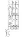
図3は、図2に示す稼働情報に対して、相関係数を求める処理を行った結果を示すものであり、処理結果が相関係数行列として求められていることを示している。図3に示す例では、サーバ1のCPU使用率とサーバ2のCPU使用率との相関係数が「0.93」、サーバ1のCPU使用率とDBクエリ数との相関係数が「0.75」、サーバ2のCPU使用率とDBクエリ数との相関係数が「0.89」等となっている。 FIG. 3 shows a result of processing for obtaining a correlation coefficient for the operation information shown in FIG. 2, and shows that the processing result is obtained as a correlation coefficient matrix. In the example shown in FIG. 3, the correlation coefficient between the CPU usage rate of the server 1 and the CPU usage rate of the
相関関数は、2次元のデータにおける変量間の関係をある1つ係数で表現する手法であり、相関係数は、2つの変量間の相関関係の程度を表す数値である。いま、ある集合(xi, yi)、xi∈X、yi∈Yという2次元データ集合が存在した場合、下式(1)で、相関係数RXYは−1≦RXY≦1の範囲で与えられる。The correlation function is a technique for expressing the relationship between variables in two-dimensional data with one coefficient, and the correlation coefficient is a numerical value indicating the degree of correlation between the two variables. Now, if there is a two-dimensional data set of a certain set (xi, yi), xi∈X, yi∈Y, the correlation coefficient RXY is in the range of −1 ≦ RXY ≦ 1 in the following equation (1). Given.

なお、相関係数の値(RXYの絶対値|RXY|)については一般的に次の特性が認められている。|RXY|≦0.2…ほとんど相関がなく、0.2≦|RXY|≦0.4…弱い相関があり、0.4≦|RXY|≦0.7…中程度の相関があり、そして、0.7≦|RXY|…高い相関がある。The value of the correlation coefficient (absolute value of RXY | RXY |) generally following characteristics are observed for.│R XY │≤0.2 ... Almost no correlation, 0.2 ≤ | RXY │≤0.4 ... weak correlation, 0.4 ≤ | RXY │≤0.7 ... moderate correlation, and 0.7 ≤ | RXY │ ... highly correlated.
図1のモデル生成部104は、本装置で基準(標準)となる複数の稼働モデルを定義してモデル情報DB105に登録したり、追加したりするための動作を行う。各稼働モデルは、意図的に障害を発生させるなどして所望の状態を作り出し、稼働情報収集部101で各構成要素から稼働情報を実際に収集することで作成することができる。ここで、各稼働モデルは、正常状態、正常状態で比較的アクセスが増大した状態、APアプリ(アプリケーション)異常負荷時状態、APサーバ障害状態、エラーアクセス増大、ハードディスク・エラー多発状態等の稼働状態を所定の形式で表したものであり、各構成要素の稼働情報間の統計的分析値を用いて定義される。図4および図5にモデル情報DB105の登録情報(モデル情報テーブル)の一例を示した。 The
図4に示す例では、複数の稼働モデルに対応させて(この場合、APアプリ異常負荷、エラーアクセス増大の2つの稼働モデルに対応させて)、モデルID(Identification)、対応ID、通知ID、モデルデータによってモデル情報テーブルの各レコードが構成されている。モデルIDは各稼働モデルの識別情報であり、対応IDはその状態が発生した場合に取るべき対応を特定する情報であり、通知IDはその状態が発生した場合に通知すべきアラート通知先等の内容を特定する情報であり、モデルデータはその状態で取得された構成要素の稼働情報間の統計的分析値である。対応IDと通知IDに対応する具体的内容は、図1の対応情報DB109に記憶されている。モデルデータは、例えば相関係数を統計的分析値として用いる場合には、図5に示すような各構成要素の稼働情報間の各相関係数からなる相関係数行列となる。この各モデルの定義データは、実際のデータと比較処理を行う際に比較基準値の中央値として用いられ、所定の幅を持たせた上で各データ間の比較が行われるようになっている。すなわち、中央値を基準として所定の幅を持たせた値が各モデルの定義データとなる。ただし、本実施の形態では、複数のモデル間の自他識別性を向上させるため、モデル情報DB105に登録される各定義データに対しては次のような中央値の変更処理を予め行うようにしている。 In the example shown in FIG. 4, corresponding to a plurality of operation models (in this case, corresponding to two operation models of AP application abnormal load and error access increase), model ID (Identification), correspondence ID, notification ID, Each record of the model information table is composed of model data. The model ID is identification information of each operation model, the correspondence ID is information for specifying a correspondence to be taken when the state occurs, and the notification ID is an alert notification destination to be notified when the state occurs. The model data is a statistical analysis value between the operation information of the constituent elements acquired in the state. Specific contents corresponding to the correspondence ID and the notification ID are stored in the
図5は、モデル情報DB105に登録される相関係数行列の一例を示す図であり、図3に示す前処理部103で作成された相関係数行列に対して、モデル生成部104によって中央値の変更処理を行ったものである。中央値の変更処理は、先に登録された他のモデルと、相関係数行列の各要素が同一あるいは非常に近い値とならないようにするためのものである。図6を参照して、この中央値変更処理について説明する。 FIG. 5 is a diagram illustrating an example of the correlation coefficient matrix registered in the
図6は、モデル生成部104による中央値変更処理を含むモデル追加処理の流れを示すフローチャートである。入力データは、前処理が行われた中間データ(図3参照)、コメント、対応ID、通知IDである(コメント、対応ID、通知IDは、モデル作成者が与える。ただし、対応ID、通知IDは少なくとも一方があればよい)。データの置き換え処理(ステップS11)では、入力(インプット)されたデータを事前に定義されたレンジ幅の(○○〜○○)の中央値の形式に置き換える処理を行う。インプットのデータが、そのレンジに入っていれば変更可能であるとする。すなわち、インプットデータが0.65であり、レンジ幅が0.2であれば、0.55〜0.75の範囲で中央値を設定できるとしている(図7参照)。ただし、レンジ幅はチューニングパラメータとして、モデル毎に変更可能とすることができる。初期値はインプットの値を使用する。 FIG. 6 is a flowchart showing a flow of model addition processing including median value change processing by the
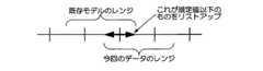
事前の限度回数Nを超えていない場合には(ステップS12で「No」)、既存モデルとの比較を行う(ステップS14)。既存モデルとの比較は、すでに存在するモデルとすべての要素にレンジの重複がある場合には両方のモデルの状況と判断されてしまうのでそのようなモデルを登録しないようにするためのチェック作業である。明確な差がある場合には(ステップS15で「Yes」)、モデル情報DB105のすでに登録されているレコード分の回数、比較対象の既存モデルを変化させながらステップS14の処理を繰り返し行う(ステップS16〜ステップS13〜ステップS14〜ステップS15〜ステップS16〜…)。ステップS15では、例えば図8に示すように、既存モデルのレンジと、今回のインプットデータのレンジとの重複部分(矢印太線)が所定の値以下であるかどうかを確認し、所定の値以下である場合に明確な差があると判定する。 When the limit number N in advance is not exceeded (“No” in step S12), comparison with the existing model is performed (step S14). The comparison with the existing model is a check to prevent the registration of such a model because it will be judged as the situation of both models if there is a range overlap between the existing model and all elements. is there. If there is a clear difference (“Yes” in step S15), the process of step S14 is repeated while changing the number of records already registered in the
一方、明確な差が無い場合には(ステップS15で「No」)、重複が少ない部分を走査する(ステップS18)。ステップS18では、差がないと判断された要素についてレンジ間の重なりが少ない部分をリストアップして、データの置き換え候補として、ステップS11のデータの置き換え処理に渡される。ステップS11では置き換え候補に基づいて中央値を変更する処理を行う。 On the other hand, if there is no clear difference (“No” in step S15), a portion with less overlap is scanned (step S18). In step S18, a part having a small overlap between ranges of elements determined to have no difference is listed and transferred to the data replacement process in step S11 as a data replacement candidate. In step S11, the median is changed based on the replacement candidate.
以上のようにして、すべての既存モデルと明確な差がある状態となったところで、今回のインプットデータがモデル情報DB105に追加される(ステップS17)。また、コメント、対応ID、通知IDもセットされる。ただし、ステップS11のデータの置き換え処理が所定の限界回数Nを超えた場合には、処理不能として、エラー処理へと引き継がれる(ステップS12で「Yes」)。 As described above, when there is a clear difference from all existing models, the current input data is added to the model information DB 105 (step S17). A comment, corresponding ID, and notification ID are also set. However, if the data replacement process in step S11 exceeds the predetermined limit number N, it is assumed that the process cannot be performed, and the error process is taken over (“Yes” in step S12).
以上の構成および処理によって、モデル情報DB15に稼働モデルが定義される。次に、図1を参照して、定義した稼働モデルを利用した監視処理について説明する。 The operation model is defined in the
図1の判断部106は、定義されている稼働モデルと未知のデータ(新たに収集した稼働情報)との判断を行う。この判断部106は、モデル生成部104と排他的に動作する。つまり、稼働情報収集部101によって収集され、稼働情報DB102に記憶された監視対象システム10の稼働情報は、前処理部103によって統計処理された後、判断部106へ入力される。判断部106は、前処理部103で求めた統計的分析値を、モデル情報DB105に記憶された統計的分析値と比較することで、収集した稼働情報に対応する稼動モデルを求める判断を実行する。なお、本実施の形態では、まず、厳密に一致するモデルを探索し、厳密に一致するモデルが見つからない場合には、類似するモデルを探索する処理を行うようにしている。判断部106は、定期的に、あるいは障害のアラートや、提供サービスのレスポンス低下などをトリガとしてこれらの処理を行う。 The
図9を参照して判断部106による処理について説明する。入力データは、例えば統計的分析値が相関係数であるとすれば図3に示すような前処理が行われた中間データとなる。まず、新たな処理の開始に際してレンジ外の要素の個数を記憶する記憶領域(ステップS25参照)が初期化される。ステップS22では、既存モデルとの比較処理が行われる。既存モデルとの比較処理では、前処理が行われた中間データの各要素(相関係数行列の各要素)がモデルのレンジに入るかが計算される。例えば今回の比較対象データと、あるモデル(今回選択中のモデル情報DB105のレコードに含まれる各要素のレンジ)を比較した結果が、図10に示すようになった場合(太線で示すレンジ内に今回の要素が含まれる場合)、この要素についてはOK(レンジに入っている)とされる。これを要素の個数回繰り返し行い、中間データの全要素について既存モデルの対応する要素との比較を行う。 Processing performed by the
次に、すべての要素がそのモデルのレンジに入っているかを判定し(ステップS23)、入っている場合には(ステップS23で「Yes」)、現在の稼働状態がそのモデルの状態であると推定する。そして、コメント、対応ID、通知IDを、図1のユーザインターフェース107、アラート通知部108、対応アプリケーション連携部110に出力し、終了する。 Next, it is determined whether or not all the elements are within the range of the model (step S23). If they are included (“Yes” in step S23), the current operating state is the state of the model. presume. Then, the comment, the corresponding ID, and the notification ID are output to the user interface 107, the
一方、レンジから外れる要素があった場合には(ステップS23で「No」)、外れた個数が他のモデルに対して記録されているものより少ないかを判定し、少ない場合には(ステップS24で「Yes」)、外れた個数とモデルIDを所定の記憶領域に記録する(ステップS25)。ステップS22以降の処理を、モデル情報DB105に定義されている各レコード(各モデル)に対して実行する。その際、すべての要素がレンジに入るモデルがあれば処理を終了するが(ステップS23で「Yes」の場合)、すべての要素がレンジに入るモデルが無い場合には、記録している外れの個数が最も少ないモデルのIDと個数を引数として、類似マッチングフローへと処理を進める(ステップS27)。 On the other hand, if there is an element that is out of range (“No” in step S23), it is determined whether the number of outliers is smaller than those recorded for other models, and if it is less (step S24). And "Yes"), the number and model ID that have been removed are recorded in a predetermined storage area (step S25). The processing after step S22 is executed for each record (each model) defined in the
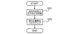
図11は、類似マッチングフローの一例を示すフローチャートである。入力データは、前処理が行われた中間データ(図3参照)と、図10のステップS25で記録された外れの個数が最も少ないモデルIDである。この場合、モデルの再探索は行われず、入力されたモデルIDで指定されるモデルが類似するモデルとして出力される。ただし、その際、再度比較を行い(ステップS31)、外れた要素をリストアップして(ステップS32)、類似であることのフラグ、コメント、通知IDを、ユーザインターフェース107およびアラート通知部108に出力し、処理を終了する。ただし、一致ではなく類似であるので、対応アプリケーション連携は行わない。 FIG. 11 is a flowchart illustrating an example of a similar matching flow. The input data is the intermediate data (see FIG. 3) on which preprocessing has been performed and the model ID with the smallest number of deviations recorded in step S25 in FIG. In this case, the model is not searched again, and the model specified by the input model ID is output as a similar model. However, at that time, the comparison is performed again (step S31), the removed elements are listed (step S32), and the similarity flag, comment, and notification ID are output to the user interface 107 and the
上記で図10および図11を参照して説明した判断部フローの流れでは、図12に示すように、基本的には厳密なマッチング(ステップS41)を行い、厳密なマッチングができない場合に回数による類似マッチング(ステップS42)を行うこととしている。これに対し、検定を用いる類似マッチングを追加して、精度向上を図ることも可能である。すなわち、図13に示すように、まず、厳密なマッチングを行い(ステップS51)、厳密なマッチングができない場合に検定を用いるマッチングを行い(ステップS52)、そして、検定を用いるマッチングで所定条件を満たすモデルが得られない場合に回数による類似マッチングを行うようにする(ステップS53)ことも可能である。 In the flow of the determination unit flow described above with reference to FIGS. 10 and 11, basically, as shown in FIG. 12, strict matching is basically performed (step S <b> 41). Similar matching (step S42) is performed. On the other hand, it is possible to improve accuracy by adding similar matching using a test. That is, as shown in FIG. 13, first, exact matching is performed (step S51). When exact matching is not possible, matching using a test is performed (step S52), and the predetermined condition is satisfied by matching using the test. When a model cannot be obtained, it is possible to perform similar matching based on the number of times (step S53).
図14は、図1の判断部106で検定によるマッチング(類似マッチング追加例)を行う場合の処理の一例を示すフローチャートである。この場合、前提として、モデル情報DB105のモデルデータには、相関係数行列に加え、分散共分散行列とサンプル数を予め定義しておく。分散共分散行列の定義の仕方は、上述した相関係数行列のものと同様である。また、前処理部103からは、収集した稼働情報から得られる相関係数行列のほか分散共分散行列とサンプル数が入力される。外れの個数とモデルIDの入力は必要としない。 FIG. 14 is a flowchart illustrating an example of processing in the case where matching is performed by testing (similar matching addition example) in the
図14の類似判定フローでは、まず、モデル情報DB105に定義されている既存モデルの分散共分散行列と、入力された分散共分散行列とを用いて検定が行われる(ステップS62)。そして、検定の結果得られた検定統計量を所定の有意水準と比較して、検定が採択される場合には(ステップS63で「No」)、そのモデルを類似モデルに決定する。一方、検定が棄却された場合には(ステップS63で「Yes」)、モデルを変更し、検定を再度実行する(ステップS64〜ステップS61〜ステップS62〜…)。モデル情報DB105のレコードの回数繰り返しても採択されるモデルが見つからない場合(すべてのモデルが棄却された場合)には、図11を参照して説明した回数による類似マッチングの処理へ移行させる(ステップS65)。 In the similarity determination flow of FIG. 14, first, a test is performed using the variance-covariance matrix of the existing model defined in the
なお、ステップS62およびステップS63における検定処理は、次のようにして行うことができる。ここで、入力されるP個の稼動情報から求められるP×P行列である分散共分散行列とサンプル数をS,N、モデルの分散共分散行列とサンプル散をS’,N’とする。この時の差の検定は次のようにして行うことができる。 In addition, the verification process in step S62 and step S63 can be performed as follows. Here, it is assumed that the variance-covariance matrix and the number of samples, which are P × P matrices obtained from the input P pieces of operation information, are S and N, and the model variance-covariance matrix and sample variance are S ′ and N ′. The test of the difference at this time can be performed as follows.
1.分散共分散行列とサンプル数から平方和積和行列の行列式を下式(2)にて求める。1. The determinant of the sum-of-squares product-sum matrix is obtained by the following equation (2) from the variance-covariance matrix and the number of samples.
2.モデルと入力をあわせた形で平方和穏和行列の行列式を下式(3)にて求める。2. The determinant of the sum of squares and the sum of the model and input is obtained by the following equation (3).
3.ウィルクスのΛ統計量を下式(4)にて求める。3. Wilkes' Λ statistic is calculated by the following equation (4).
4.有意水準αを定めて検定統計量F0を下式(5)にて比較して検定とする。ここで、F(P,N+N’−P−1)(α)は自由度(P,N+N’−P−1)のαパーセント点を意味する。4). A significance level α is determined and the test statistic F0 is compared by the following equation (5) to obtain a test. Here, F(P, N + N′−P−1) (α) means the α percentage point of the degree of freedom (P, N + N′−P−1).
以上のようにして判断部106で一致または類似する稼働モデルが求められると、その結果は以下のようにして提示されたり、利用されたりする。すなわち図1のユーザインターフェース107は、判断部106から提供される情報に基づいて、表示装置100aあるいは表示装置200aを用い、Webブラウザや専用ビュアーのGUI(Graphical User Interface)によって管理者(操作者)に情報を提示する機能を提供する。 When the
アラート通知部108は、判断部106から提供される情報と対応情報DB109に格納されている情報とに基づいて、管理者に対しては電子メールやページャ、本装置の上位に位置する統合運用管理ソフトウェアに対してはネットワークソケットなどを利用して、状態等を通知する。 Based on the information provided from the
対応アプリケーション連携部110は、一致する稼働モデルが求められた場合には、判断部106から提供される情報と対応情報DB109に格納されている情報とに基づいて、所定の稼働状態を判断したときにそれをトリガとして動作するアプリケーションに対してAPI(Application Program Interface)を利用して指示を行う。 When a corresponding operation model is obtained, the corresponding
対応情報DB109は、アラート送信や、対応アプリケーションの情報を格納する。格納する情報は、事前に定義しておく。図15に一例を示した。図15に示す例において対応情報DB109には、対応動作テーブル109aとアラート通知テーブル109bとが記憶されている。対応動作テーブル109aには、対応IDに対応づけて連携可能アプリケーションや動作の定義がなされている。アラート通知テーブル109bには、通知IDに対応づけて管理者や他の運用管理、セキュリティ管理ツールへの通知内容の定義がなされている。これらの対応IDと通知IDは、図4を参照して説明したモデル情報DB105に定義されている対応IDと通知IDにそれぞれ対応している。 The
例えば現在の稼働情報が、図4のモデル情報DB105(モデル情報テーブル)のモデルID「001」の稼働モデル(「APアプリ異常負荷」、対応ID「003」、通知ID「002」)に一致すると判断された場合には、アラート通知部108は、アラート通知テーブル109b内の通知ID「002」に設定されたあて先の電子メール(形式「××@○○」)に状態等の通知を行う。一方、対応アプリケーション連携部110は、対応動作テーブル109a内の対応ID「003」に設定された動作(「APサーバ追加」)を行うための所定の処理を行う。 For example, when the current operation information matches the operation model (“AP application abnormal load”, correspondence ID “003”, notification ID “002”) of the model ID “001” in the model information DB 105 (model information table) of FIG. If it is determined, the
以上に説明したように、本発明の実施の形態では、まず、監視対象となるサーバ、ネットワーク機器等から、CPU使用率のようなハードウェア稼動情報、またWebサーバ(HTTP(HyperText Transfer Protocol)サーバ)であれば、アクセスの状況といったアプリケーションレベルの情報を定期的に取得するようにし、正常なアクセス時や、障害発生時といった各状況における稼動情報から、各状況を特徴付ける“取得値間の関連”を相関分析・主成分分析といった統計的手法を用いて算出し、各状況のモデルを定義してモデル情報DB105に保持しておく。 As described above, in the embodiment of the present invention, first, hardware operation information such as the CPU usage rate, a Web server (HTTP (HyperText Transfer Protocol) server) from a server or network device to be monitored. ), Application-level information such as access status is periodically acquired, and “relationship between acquired values” that characterizes each status from operation information in each status such as normal access or when a failure occurs Are calculated using a statistical method such as correlation analysis / principal component analysis, and a model for each situation is defined and stored in the
そして、運用時には、定期的に、あるいは障害のアラートや、提供サービスのレスポンス低下などをトリガとして、現在の稼働情報に対して定義したモデルと同様の統計的手法を行い、モデル情報DB105に定義したモデルと比較して、マッチしたモデルの状況を現在置かれている状況として識別する。これによって管理者はシステムの状況を容易に理解することが可能となり、個別コンポーネントを見ての対応ではなく、システムにより適した対応を取ることができる。また、モデル情報DB105に通常時の稼働モデルを定義しておくことで、いずれのモデルに対してもマッチしない場合、その状況は、通常の状況時が持つ取得値間の関連の一部が崩れたものであると考えることができる。つまり、対策が必要な異常状態ではないとしても、通常の状態から若干ずれているような状態であると考えることができる。そこで本実施の形態では、そのような場合にモデル情報DB105に保持しているモデルで最も類似性が高いものとその差分を提示することにした。これによって、管理者は取得値間の関連が崩れている部分に異常があるあるいは発生する可能性があることを推定することができる。 At the time of operation, a statistical method similar to the model defined for the current operation information is performed periodically or triggered by a failure alert or a decrease in response of the provided service, and is defined in the
本実施形態によれば、従来に比べより詳細にシステムの状態を識別・提示できるので、管理者の状況判断の支援となり、システム全体を考慮に入れた形で迅速に的確な対応を取ることができ、人為ミスの低減が図れる。 According to the present embodiment, the system status can be identified and presented in more detail than in the past, so that it is possible to support the manager's situation judgment and to take an appropriate and prompt action in consideration of the entire system. This can reduce human error.
また統計的なモデルを利用して通常の状況、障害の状況を定義することで、取得値の揺らぎや障害に近い状況に対しても、管理者に異常があることを提示することができる。例えば、Webアプリケーションのシステムにおいて、そのレスポンスが低下した場合は、正規のリクエスト量が多い、正常でないリクエストにより性能が低下している、Webサーバ、APサーバ、DBサーバ、ネットワークの何処かに処理が集中している、障害が発生しているといった状況と原因が考えられる。これらのそれぞれに対する対応は異なるが、本実施の形態によれば、これらの状況の判断と原因の切り分けを支援し、運用管理コストを低減させることが可能となる。 In addition, by defining a normal situation and a failure situation using a statistical model, it is possible to present an abnormality to the administrator even for a fluctuation of an acquired value or a situation close to a failure. For example, in a Web application system, if the response decreases, the processing is performed somewhere in the Web server, AP server, DB server, or network where the amount of regular requests is large or the performance is decreased due to an abnormal request. Possible situations and causes such as concentration and failure. Although the response to each of these is different, according to the present embodiment, it is possible to support the determination of the situation and the cause separation, and to reduce the operation management cost.
なお、稼働モデルとその対応との組み合わせには、上述したもののほか、次のようなものが考えられる。「正常なアクセスで、サーバ負荷が高い。」→サーバがダウンする前にサーバを増強する。「ワームと思われるアクセスが増加している。」→帯域を使い切る前に、該当ホストからのアクセスを遮断する。「アクセス量は多くないのにサーバ負荷が高い」→サービスを継続しながら該当サーバのプロセスの異変に対応する。 In addition to the above-described combinations of operation models and their correspondence, the following may be considered. "Normal access and high server load."-> Increase servers before the server goes down. “Access that seems to be worms is increasing.” → Block access from the host before using up the bandwidth. “The amount of access is not large but the server load is high.” → Respond to changes in the process of the server while continuing the service.
また、上記実施の形態において、統計的分析手法として主成分分析を用いる場合には次のような構成とすることができる。すなわち、一般的に主成分分析においては、主成分(固有値)を導出すると第1主成分に総合得点、第2主成分以降に特徴をよくあらわす主成分を得ることかできる。そこで、第2主成分以降の値により、評価することにより、比較を行うようにすれば、各稼働状態の識別をより明確に行うことができると考えられる。 Moreover, in the said embodiment, when using principal component analysis as a statistical analysis method, it can be set as the following structures. That is, in general, in the principal component analysis, if a principal component (eigenvalue) is derived, a total score can be obtained for the first principal component, and a principal component that well represents features after the second principal component can be obtained. Therefore, it is considered that each operation state can be identified more clearly if a comparison is made by evaluating the values after the second principal component.
また、本発明の実施の形態は、上記のものに限定されず、例えば、図1の各構成を統合したり、分割したり、ネットワークを介して分散して配置したり、他の構成を追加したりするような変更を適宜行うことができる。例えば図1の構成で、管理サーバ100とネットワーク12との間にファイアウォールを追加して、管理サーバ100に対するパケットに一定の制限を加えることなどが可能である。また、稼働モデルの作成は、実際に収集した稼働情報に基づく場合に限らず、設計によって、あるいは類似のシステムにおける稼働モデルを利用して作成することも可能である。 In addition, the embodiment of the present invention is not limited to the above-described one. For example, the components shown in FIG. 1 are integrated, divided, distributed via a network, and other configurations are added. Changes can be made as appropriate. For example, in the configuration of FIG. 1, it is possible to add a firewall between the
また、管理サーバ100は、コンピュータやその周辺装置とそれらのハードウェア資源を用いて実行されるプログラムとによって構成することができるが、そのプログラムは、コンピュータ読み取り可能な記録媒体あるいは通信回線を介して配布することが可能である。 In addition, the
1…ネットワーク、10…監視対象システム、11…ファイアウォール、12…ネットワーク、13…NIDS、14…Webサーバ、15…APサーバ、16…DBサーバ、100…管理サーバ、101…稼働情報収集部、102…稼働情報DB、103…前処理部(統計処理)、104…モデル生成部、105…モデル情報DB、106…判断部、107…ユーザインターフェース、108…アラート通知部、109…対応情報DB、110…対応アプリケーション連携部、200…クライアント
DESCRIPTION OF SYMBOLS 1 ... Network, 10 ... Monitored system, 11 ... Firewall, 12 ... Network, 13 ... NIDS, 14 ... Web server, 15 ... AP server, 16 ... DB server, 100 ... Management server, 101 ... Operation information collection part, 102
Claims (10)
Translated fromJapanese稼働情報収集手段で収集した稼働情報を記憶する稼働情報記憶手段と、
記憶した各要素の稼働情報間の統計的分析値を求める統計処理手段と、
複数の稼動モデルに対応した各要素の稼働情報間の統計的分析値を予め記憶したモデル情報記憶手段と、
統計処理手段で求めた統計的分析値をモデル情報記憶手段に記憶された統計的分析値と比較することで、収集した稼働情報に対応する稼動モデルを求める判断部と
を備えることを特徴とする運用管理支援装置。Operation information collecting means for collecting operation information of three or more elements every predetermined time;
Operation information storage means for storing operation information collected by the operation information collection means;
Statistical processing means for obtaining a statistical analysis value between operation information of each stored element;
Model information storage means for storing in advance statistical analysis values between operation information of each element corresponding to a plurality of operation models;
A judgment unit for obtaining an operation model corresponding to the collected operation information by comparing the statistical analysis value obtained by the statistical processing means with the statistical analysis value stored in the model information storage means. Operation management support device.
ことを特徴とする請求項1記載の運用管理支援装置。The operation management support apparatus according to claim 1, wherein the determination unit obtains an operation model in which the comparison results match, and obtains a similar operation model if the comparison results do not match.
ことを特徴とする請求項2記載の運用管理支援装置。The determination unit obtains a similar operation model based on the number of statistical analysis values in which the comparison results are inconsistent when a similar operation model is obtained by the test and a similar operation model is not obtained by the test. The operation management support apparatus according to claim 2, wherein:
前記判断部によって稼働モデルが求められた場合に所定のアプリケーションを実行する対応アプリケーション連携手段と
をさらに備えることを特徴とする請求項1〜3のいずれか1項に記載の運用管理支援装置。A notification means for notifying a predetermined notification destination when an operation model is obtained by the determination unit;
The operation management support apparatus according to claim 1, further comprising: a corresponding application cooperation unit that executes a predetermined application when an operation model is obtained by the determination unit.
ことを特徴とする請求項4記載の運用管理支援装置。The operation management support apparatus according to claim 4, wherein the corresponding application cooperation unit does not execute a predetermined application when the obtained model is a similar operation model.
稼働情報収集段階で収集した稼働情報を記憶する稼働情報記憶段階と、
記憶した各要素の稼働情報間の統計的分析値を求める統計処理段階と、
複数の稼動モデルに対応した各要素の稼働情報間の統計的分析値を予め記憶したモデル情報記憶手段を用いて、統計処理段階で求めた統計的分析値をモデル情報記憶手段に記憶された統計的分析値と比較することで、収集した稼働情報に対応する稼動モデルを求める判断段階と
をコンピュータを用いて実行するための記述を含むことを特徴とする運用管理支援プログラム。
An operation information collection stage for collecting operation information of three or more elements every predetermined time;
An operation information storage stage for storing operation information collected in the operation information collection stage;
A statistical processing stage for obtaining a statistical analysis value between operation information of each stored element;
Statistical information stored in the model information storage means using the model information storage means that stores in advance statistical analysis values between the operation information of each element corresponding to a plurality of operation models. An operation management support program including a description for using a computer to execute a determination stage for obtaining an operation model corresponding to the collected operation information by comparing with a statistical analysis value.
Priority Applications (1)
| Application Number | Priority Date | Filing Date | Title |
|---|---|---|---|
| JP2004337411AJP2006146668A (en) | 2004-11-22 | 2004-11-22 | Operation management support apparatus and operation management support program |
Applications Claiming Priority (1)
| Application Number | Priority Date | Filing Date | Title |
|---|---|---|---|
| JP2004337411AJP2006146668A (en) | 2004-11-22 | 2004-11-22 | Operation management support apparatus and operation management support program |
Publications (1)
| Publication Number | Publication Date |
|---|---|
| JP2006146668Atrue JP2006146668A (en) | 2006-06-08 |
Family
ID=36626263
Family Applications (1)
| Application Number | Title | Priority Date | Filing Date |
|---|---|---|---|
| JP2004337411AWithdrawnJP2006146668A (en) | 2004-11-22 | 2004-11-22 | Operation management support apparatus and operation management support program |
Country Status (1)
| Country | Link |
|---|---|
| JP (1) | JP2006146668A (en) |
Cited By (19)
| Publication number | Priority date | Publication date | Assignee | Title |
|---|---|---|---|---|
| JP2008027061A (en)* | 2006-07-19 | 2008-02-07 | Internatl Business Mach Corp <Ibm> | Technique for detecting abnormal information processing apparatus |
| JP2008191839A (en)* | 2007-02-02 | 2008-08-21 | Hitachi Electronics Service Co Ltd | Abnormality sign detection system |
| JP2008217235A (en)* | 2007-03-01 | 2008-09-18 | Fujitsu Ltd | System monitoring program, system monitoring method, and system monitoring apparatus |
| JP2009199534A (en)* | 2008-02-25 | 2009-09-03 | Nec Corp | Operation management device, operation management system, information processing method, and operation management program |
| JP2009199533A (en)* | 2008-02-25 | 2009-09-03 | Nec Corp | Operation management device, operation management system, information processing method, and operation management program |
| WO2010010621A1 (en)* | 2008-07-24 | 2010-01-28 | 富士通株式会社 | Troubleshooting support program, troubleshooting support method, and troubleshooting support device |
| WO2010032701A1 (en)* | 2008-09-18 | 2010-03-25 | 日本電気株式会社 | Operation management device, operation management method, and operation management program |
| JP2010231825A (en)* | 2010-07-21 | 2010-10-14 | Fujitsu Ltd | System monitoring program, system monitoring method, and system monitoring apparatus |
| WO2011046228A1 (en) | 2009-10-15 | 2011-04-21 | 日本電気株式会社 | System operation management device, system operation management method, and program storage medium |
| JP2011146074A (en)* | 2011-04-26 | 2011-07-28 | Nec Corp | Device and system for managing operation, information processing method, and operation management program |
| JP2011146073A (en)* | 2011-04-26 | 2011-07-28 | Nec Corp | Device and system for managing operation, information processing method, and operation management program |
| JP2013525885A (en)* | 2010-04-16 | 2013-06-20 | インターナショナル・ビジネス・マシーンズ・コーポレーション | Application non-progress detection |
| JP2013242902A (en)* | 2013-07-22 | 2013-12-05 | Nec Corp | Operation management device, operation management system, information processing method, and operation management program |
| WO2014068980A1 (en)* | 2012-11-01 | 2014-05-08 | 日本電気株式会社 | Distributed data processing system and distributed data processing method |
| WO2014196129A1 (en)* | 2013-06-03 | 2014-12-11 | 日本電気株式会社 | Fault analysis device, fault analysis method, and recording medium |
| JP2014238852A (en)* | 2014-07-16 | 2014-12-18 | 日本電気株式会社 | Operation management device, operation management system, information processing method, and operation management program |
| US9658908B2 (en) | 2013-10-23 | 2017-05-23 | Fujitsu Limited | Failure symptom report device and method for detecting failure symptom |
| JP2018165857A (en)* | 2017-03-28 | 2018-10-25 | 富士通株式会社 | Analysis device, analysis system, analysis method, and analysis program |
| JP2021128538A (en)* | 2020-02-13 | 2021-09-02 | 日本電信電話株式会社 | Failure factor estimating device and failure factor estimating method |
- 2004
- 2004-11-22JPJP2004337411Apatent/JP2006146668A/ennot_activeWithdrawn
Cited By (34)
| Publication number | Priority date | Publication date | Assignee | Title |
|---|---|---|---|---|
| JP2008027061A (en)* | 2006-07-19 | 2008-02-07 | Internatl Business Mach Corp <Ibm> | Technique for detecting abnormal information processing apparatus |
| JP2008191839A (en)* | 2007-02-02 | 2008-08-21 | Hitachi Electronics Service Co Ltd | Abnormality sign detection system |
| JP2008217235A (en)* | 2007-03-01 | 2008-09-18 | Fujitsu Ltd | System monitoring program, system monitoring method, and system monitoring apparatus |
| US8225144B2 (en) | 2008-02-25 | 2012-07-17 | Nec Corporation | Operations management apparatus, operations management system, data processing method, and operations management program |
| JP2009199534A (en)* | 2008-02-25 | 2009-09-03 | Nec Corp | Operation management device, operation management system, information processing method, and operation management program |
| JP2009199533A (en)* | 2008-02-25 | 2009-09-03 | Nec Corp | Operation management device, operation management system, information processing method, and operation management program |
| US7975186B2 (en) | 2008-02-25 | 2011-07-05 | Nec Corporation | Operations management apparatus, operations management system, data processing method, and operations management program |
| US8621284B2 (en) | 2008-02-25 | 2013-12-31 | Nec Corporation | Operations management apparatus, operations management system, data processing method, and operations management program |
| WO2010010621A1 (en)* | 2008-07-24 | 2010-01-28 | 富士通株式会社 | Troubleshooting support program, troubleshooting support method, and troubleshooting support device |
| JP5267564B2 (en)* | 2008-07-24 | 2013-08-21 | 富士通株式会社 | Output program, output method, output device, troubleshooting support program, troubleshooting support method, and troubleshooting support device |
| WO2010032701A1 (en)* | 2008-09-18 | 2010-03-25 | 日本電気株式会社 | Operation management device, operation management method, and operation management program |
| US8700953B2 (en) | 2008-09-18 | 2014-04-15 | Nec Corporation | Operation management device, operation management method, and operation management program |
| WO2011046228A1 (en) | 2009-10-15 | 2011-04-21 | 日本電気株式会社 | System operation management device, system operation management method, and program storage medium |
| US8959401B2 (en) | 2009-10-15 | 2015-02-17 | Nec Corporation | System operations management apparatus, system operations management method and program storage medium |
| US10496465B2 (en) | 2009-10-15 | 2019-12-03 | Nec Corporation | System operations management apparatus, system operations management method and program storage medium |
| US9384079B2 (en) | 2009-10-15 | 2016-07-05 | Nec Corporation | System operations management apparatus, system operations management method and program storage medium |
| JP2013525885A (en)* | 2010-04-16 | 2013-06-20 | インターナショナル・ビジネス・マシーンズ・コーポレーション | Application non-progress detection |
| JP2010231825A (en)* | 2010-07-21 | 2010-10-14 | Fujitsu Ltd | System monitoring program, system monitoring method, and system monitoring apparatus |
| JP2011146073A (en)* | 2011-04-26 | 2011-07-28 | Nec Corp | Device and system for managing operation, information processing method, and operation management program |
| JP2011146074A (en)* | 2011-04-26 | 2011-07-28 | Nec Corp | Device and system for managing operation, information processing method, and operation management program |
| WO2014068980A1 (en)* | 2012-11-01 | 2014-05-08 | 日本電気株式会社 | Distributed data processing system and distributed data processing method |
| US10296493B2 (en) | 2012-11-01 | 2019-05-21 | Nec Corporation | Distributed data processing system and distributed data processing method |
| CN104769551A (en)* | 2012-11-01 | 2015-07-08 | 日本电气株式会社 | Distributed data processing system and distributed data processing method |
| CN104769551B (en)* | 2012-11-01 | 2018-07-03 | 日本电气株式会社 | Distributed data processing system and distributed data processing method |
| JPWO2014068980A1 (en)* | 2012-11-01 | 2016-09-08 | 日本電気株式会社 | Distributed data processing system and distributed data processing method |
| JPWO2014196129A1 (en)* | 2013-06-03 | 2017-02-23 | 日本電気株式会社 | Fault analysis apparatus, fault analysis method, and computer program |
| US9612898B2 (en) | 2013-06-03 | 2017-04-04 | Nec Corporation | Fault analysis apparatus, fault analysis method, and recording medium |
| WO2014196129A1 (en)* | 2013-06-03 | 2014-12-11 | 日本電気株式会社 | Fault analysis device, fault analysis method, and recording medium |
| JP2013242902A (en)* | 2013-07-22 | 2013-12-05 | Nec Corp | Operation management device, operation management system, information processing method, and operation management program |
| US9658908B2 (en) | 2013-10-23 | 2017-05-23 | Fujitsu Limited | Failure symptom report device and method for detecting failure symptom |
| JP2014238852A (en)* | 2014-07-16 | 2014-12-18 | 日本電気株式会社 | Operation management device, operation management system, information processing method, and operation management program |
| JP2018165857A (en)* | 2017-03-28 | 2018-10-25 | 富士通株式会社 | Analysis device, analysis system, analysis method, and analysis program |
| JP2021128538A (en)* | 2020-02-13 | 2021-09-02 | 日本電信電話株式会社 | Failure factor estimating device and failure factor estimating method |
| JP7384063B2 (en) | 2020-02-13 | 2023-11-21 | 日本電信電話株式会社 | Failure factor estimation device and failure factor estimation method |
Similar Documents
| Publication | Publication Date | Title |
|---|---|---|
| JP2006146668A (en) | Operation management support apparatus and operation management support program | |
| US11442803B2 (en) | Detecting and analyzing performance anomalies of client-server based applications | |
| Shen et al. | {ATTACK2VEC}: Leveraging temporal word embeddings to understand the evolution of cyberattacks | |
| US8352790B2 (en) | Abnormality detection method, device and program | |
| US7593936B2 (en) | Systems and methods for automated computer support | |
| US8352589B2 (en) | System for monitoring computer systems and alerting users of faults | |
| US8463899B2 (en) | System, method and computer program product for optimized root cause analysis | |
| US6973415B1 (en) | System and method for monitoring and modeling system performance | |
| US20070168696A1 (en) | System for inventing computer systems and alerting users of faults | |
| US8635498B2 (en) | Performance analysis of applications | |
| KR102068622B1 (en) | Failure prediction system for heterogeneous network security system | |
| EP1998252A1 (en) | Method and apparatus for generating configuration rules for computing entities within a computing environment using association rule mining | |
| EP3407564A1 (en) | Detection system for network security threats | |
| EP1661047A2 (en) | Systems and methods for automated computer support | |
| US10270799B2 (en) | Methods and systems for predicting vulnerability state of computer system | |
| WO2015136624A1 (en) | Application performance monitoring method and device | |
| US7082381B1 (en) | Method for performance monitoring and modeling | |
| Tang et al. | An integrated framework for optimizing automatic monitoring systems in large IT infrastructures | |
| US7197428B1 (en) | Method for performance monitoring and modeling | |
| JP2010250502A (en) | Device, method and program for detecting abnormal operation | |
| Tang et al. | Optimizing system monitoring configurations for non-actionable alerts | |
| Kuang et al. | Knowledge-aware alert aggregation in large-scale cloud systems: a hybrid approach | |
| KR101433045B1 (en) | System and method for detecting error beforehand | |
| CN117318988B (en) | An automated scanning and early warning management system for network security vulnerabilities based on big data | |
| JP2004348640A (en) | Network management system and network management method |
Legal Events
| Date | Code | Title | Description |
|---|---|---|---|
| A300 | Withdrawal of application because of no request for examination | Free format text:JAPANESE INTERMEDIATE CODE: A300 Effective date:20080205 |